

Page 1

CCS Technical Documentation
RH-3 Series Transceivers
Troubleshooting — Antenna
Issue 1 06/2003 Confidential Nokia Corporation
Page 2
RH-3
Troubleshooting — Antenna CCS Technical Documentation
Page 2 Nokia Corporation Confidential Issue 1 06/2003
Page 3

RH-3
CCS Technical Documentation Troubleshooting — Antenna
Contents
Page No
Troubleshooting - Antenna ............................................................................................ 5
Whip Antenna ..............................................................................................................5
Visual Quality Requirements.................................................................................... 5
PIFA Antenna ..............................................................................................................6
Visual Quality Requirements.................................................................................... 6
Failures and Corrective Measures.................................................................................. 8
Appearance of Phone ...................................................................................................8
Antenna Position into D-cover.................................................................................. 8
Internal Antenna ..........................................................................................................9
Damaged RF Feed or Ground Pins ........................................................................... 9
Wrong Internal Antenna Installed........................................................................... 10
Obstructed RF Feed and/or Ground Pads for the Main and GPS Antennas ........... 11
Broken or Missing Bottom Antenna Clip ............................................................... 12
Obstructed Whip Stopper........................................................................................ 12
Grounding of Display Frame................................................................................... 13
Misinstalled Whip................................................................................................... 14
Damaged Whips...................................................................................................... 15
Detuning Circuit for Bottom Antenna Clip............................................................. 15
Testing CDMA Antenna.............................................................................................. 15
Calibration Factors.................................................................................................. 15
Calibration Factor for Cell800 frequency ............................................................... 15
Measurement Procedure for Cell800/PCS1900 phones.......................................... 15
Testing GPS Antenna................................................................................................... 16
Calibration Factor for GPS...................................................................................... 16
Measurement Procedure for GPS Antenna ............................................................. 16
Issue 1 06/2003 Nokia Corporation Confidential Page 3
Page 4

RH-3
Troubleshooting — Antenna CCS Technical Documentation
Page 4 Nokia Corporation Confidential Issue 1 06/2003
Page 5
RH-3
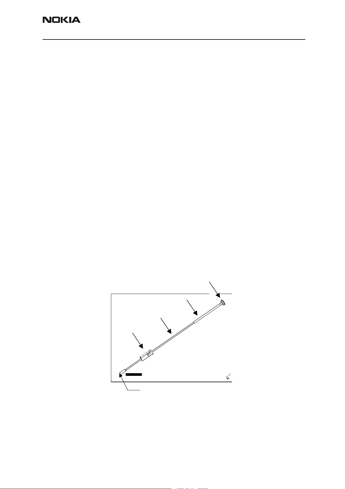
Button
Button
Wire
Cap
Tube
CCS Technical Documentation Troubleshooting — Antenna
Troubleshooting - Antenna
This troubleshooting guide addresses potential failures that will affect antenna performance of the RH-3/RH-3P phone, and discusses methods for correction of these failures.
Whip Antenna
Visual Quality Requirements
Following are the minimum acceptable visual quality standards of the RH-3/RH-3P whip
assembly. This information may be used as an inspection guideline.
• No physical crack or any mechanical defects.
• No oil, dirt or particles are presented on parts.
• Button parting line (flash or offset) less than 0.1 mm.
• Color match to code Nokia Jonathan Gray (GY7999).
• Wire tube must completely cover the NiTi wire. No uncovered NiTi wire
can be seen from the tube side.
• No wire burr gr eater than 0.1 mm can be se en from the stopper.
• Check if the proper pr inti n g i s pres en t (ca n be found on the plastic cap).
• The button must be perpendicular to the tube. This can be interpreted
as maximum of 5°.
No wire burr greater than
0.1 mm can be seen
outside of the stopper.
Figure 1: Whip Assembly
Issue 1 06/2003 Nokia Corporation Confidential Page 5
Page 6

RH-3
offset) must be less than
Check the part printing.
Button must be perpendicular to the tube
Troubleshooting — Antenna CCS Technical Documentation
Parting line (flash or
PIFA Antenna
Visual Quality Requirements
Following are the minimum acceptable visual quality standards of the RH-3/RH-3P PIFA
antenna assembly. This information may be used as an inspection guideline.
• Gloves must be used when handling antennas. Do not touch radiator
with bare hands.
• Maximum burrs of any met al part must be less than 0.01 mm, except for
burrs on radiator resulted by antenna tuning.
• General parting lines, or flash lines (including gate) must be less than
0.20 mm.
• No visual crack or any mechanical defects.
0.1 mm.
Figure 2: Whip Assembly
• Proper marking must present.
• No oil, dirt, or particles are present on parts.
• Radiator must be aligned with plastic housing.
• GPS antenna contacts must be inside the plastic housing.
• Radiator must be flat and no warp.
Page 6 Nokia Corporation Confidential Issue 1 06/2003
Page 7

RH-3
Proper printing must be present. (See Figure 10).
CCS Technical Documentation Troubleshooting — Antenna
• All pins must be at same level.
• Check if proper printing is present.
Pins must be at
the same level.
Figure 3: PIFA Module showing antenna feed pins
Figure 4: PIFA Actual Element
Issue 1 06/2003 Nokia Corporation Confidential Page 7
Page 8

RH-3
Troubleshooting — Antenna CCS Technical Documentation
Failures and Corrective Measures
Appearance of Phone
Figure 6: Back of RH-3/RH-3P phone, whip retracted and whip extended
Note in Figure 6 that when the whip is properly installed that the cap clicks into the
D-cover when the whip is fully retracted.
Antenna Position into D-cover
Internal antenna and whip are assembled into D-cover as shown in Figure 7. Whip must
be inserted prior to inserting internal antenna
Figure 5: Front of RH-3/RH-3P handset
Page 8 Nokia Corporation Confidential Issue 1 06/2003
Page 9

RH-3
CCS Technical Documentation Troubleshooting — Antenna
.
Figure 7: RH-3 D-cover assembly
If the internal antenna is missing, install one. If the radiator looks obviously damaged,
then replace the internal antenna.
If no internal antenna is installed, the antenna gain will be degraded by more than
25 dB.
If the whip is missing, then remove the internal antenna, install a whip and reinstall the
internal antenna.
Internal Antenna
RH-3/RH-3P internal antenna shown in Figure 8 has a metal sheet (main antenna radiator) and a metal strip (GPS antenna) attached to a plastic carrier (Models 2285 and 2270
only).
Figure 8: RH-3/RH-3P internal antenna from two different view angles
Damaged RF Feed or Ground Pins
Both main and GPS antennas have pins (spring clips) that should properly touch the
PWB. Positioning of these pins is shown in Figure 9.
Issue 1 06/2003 Nokia Corporation Confidential Page 9
Page 10

RH-3
Troubleshooting — Antenna CCS Technical Documentation
Figure 9: Back view of RH-3/RH-3P internal antenna
If either the RF feed pin or ground pin are broken, or bent such that either pin will not
touch the PWB, then the internal antenna must be replaced. If the springs for the RF or
ground pin appear damaged, then the internal antenna must be replaced.
If the RF feed pin of main antenna doesn't touch the PWB, then the antenna gain will
degrade by more than 25 dB and GPS antenna will be detuned. If the ground pin of main
antenna doesn't touch the PWB then the antenna gain may degrade about 5 to 10 dB
and GPS antenna will be detuned.
If the RF feed pin of GPS antenna doesn't touch the PWB, then the GPS antenna gain will
degrade by more than 20dB. If the ground pin of GPS antenna doesn't touch the PWB,
then the GPS antenna gain may degrade more than 5dB.
Wrong Internal Antenna Installed
The RH-3/RH-3P and RH-17 antennas share the same mechanical interface with the
D-cover. So either antenna can be installed in either phone. However, there are three
important differences between RH-3/RH-3P and RH-17 internal antennas:
1 Models 2285 and 2270 RH-3/RH-3P antenna have a GPS strip (antenna) while
the RH-17 antenna does not
2 The slot pattern is very different between the two antennas; and
3 RH-3/RH-3P and RH-17 antennas are marked on their radiators with "F" and "H"
respectively. See Figure 10.
Page 10 Nokia Corporation Confidential Issue 1 06/2003
Page 11

RH-3
CCS Technical Documentation Troubleshooting — Antenna
Figure 10: Top views of internal antenna (RH-3 at left; RH-17 at right)
Installing the RH-17 antenna in the RH-3/RH-3P phone will not be compliant with
Nokia’s FCC submission, as RH-17 is a single-band antenna (no PCS) and it doesn't have
a GPS antenna.
If the wrong antenna is installed, install the correct one.
If the slot in the radiator has a significantly different shape, then the correct internal
antenna must be installed. Be aware that the shape of the slot can vary slightly. The
length of the horizontal slot and the opening of the vertical slot can vary by few millimeters, because the antennas are tuned for each batch of plastic frames. If there is any
other obvious damage to the radiator (dents, corrosion), then the antenna should be
replaced. If the pin gets stuck or has excessive friction in the plastic tube/guiding feature, then the spring will not work properly, and the antenna should be replaced.
Obstructed RF Feed and/or Ground Pads for the Main and GPS Antennas
Figure 11: PWB layout of RF feed and ground pads, and bottom antenna clip
If the any of RF feed or ground pins are obstructed, removed, or covered, then the RF pin
will not touch the PWB and the antenna performance will degrade. See the antenna per-
Issue 1 06/2003 Nokia Corporation Confidential Page 11
Page 12

RH-3
Troubleshooting — Antenna CCS Technical Documentation
formance degradation section if any pin doesn't touch the PWB.
If corrosion is present or the pad is missing, then most likely the PWB and the phone
needs to be replaced. If either pad is obstructed or covered, the pad should be cleared
and/or cleaned.
Broken or Missing Bottom Antenna Clip
If the bottom antenna clip does not contact the whip stopper, when the whip is fully
retracted, the internal antenna gain will degrade by about 4-5dB at Cell band and
3-10dB at PCS band when whip is retracted. If the antenna clip is installed backwards, is
damaged, or is missing, then install a new bottom antenna clip in the correct position.
Obstructed Whip Stopper
Figure 12: Bottom antenna clip
Figure 13: Whip stopper as shown when the whip is fully retracted
If the whip stopper is corroded or blocked by the whip straw, then the whip assembly
needs to be replaced. If the whip stopper is obstructed or dirty, then the obstruction
Page 12 Nokia Corporation Confidential Issue 1 06/2003
Page 13

RH-3
CCS Technical Documentation Troubleshooting — Antenna
and/or dirt needs to be removed. If the whip stopper doesn't properly contact the bottom antenna clip, then the internal antenna gain will degrade by about 4-5dB at Cell
band and 3-10dB at PCS band when whip is retracted.
Grounding of Display Frame
Figure 14: Back view of display assembly
Note that the display frame is grounded to the PWB through the two ground clips. The
grounding of the display frame will impact the radiation performance of the phone. If
the clips are not touching the PWB, or are corroded or obstructed, then the display frame
should be replaced.
The following figures show the contact between the display frame ground clips and the
PWB in greater detail.
Figure 15: Contacts of display frame clips with side plating of PWB
Issue 1 06/2003 Nokia Corporation Confidential Page 13
Page 14

RH-3
Troubleshooting — Antenna CCS Technical Documentation
Figure 16: View of display ground clip in assembled phone with A-cover removed
Misinstalled Whip
The whip is locked into the D-cover when the internal antenna frame is installed. There is
a feature in the plastic frame of the internal antenna that interlocks with the locking
feature of the whip. The whip plug has the locking feature, and also has a key that is
designed to make it difficult to install the whip plug with the wrong rotation. If the whip
plug does get installed with the wrong rotation, then the whip will not be visible as seen
through the locking feature as shown in Figure 17. In this case, if the whip cannot be
removed, then the D-cover assembly will need to be replaced. Otherwise, simply replace
the whip.
Figure 17: Locking feature for whip
Page 14 Nokia Corporation Confidential Issue 1 06/2003
Page 15

RH-3
CCS Technical Documentation Troubleshooting — Antenna
Damaged Whips
Figure 18: Whip stand-alone in retracted and extended positions
The above figure shows what the whip should look like when it is retracted and
extended. If the whip is damaged, simply use another.
Detuning Circuit for Bottom Antenna Clip
Figure 12 shows the bottom antenna clip. The detuning circuit is right next to the bottom antenna clip. If the detuning circuit is not installed properly, then the internal
antenna gain will degrade by about 4-5dB at Cell band and 3-10dB at PCS band. The
detuning circuit consists of a 1nH coil inductor. If the inductor is missing, then install
one.
Testing CDMA Antenna
Calibration Factors
Defining AMS RF coupler CPL-8 calibration numbers will be conducted in the test
adapter MJF-28. The calibration numbers will be obtained by utilizing a phone with
known RF and antenna performance. Each test adapter should only require a single calibration on PCS1900 and GPS bands at used test frequencies. Additional calibrations
should only be needed if the test adapter is substantially modified (reassembled, changed
parts, dropped, etc.).
Calibration Factor for PCS1900 frequency
Transmitter of the phone with known output power and antenna performance will be
turned on at the maximum output power (all bits up) by using call box. The transmitted
power will be measured on the RF connector and through coupler at CDMA PCS channel
1175. The difference between the transmitted and received powers will be used as the
calibration number (path loss on Cell band including coupler, cable, and attenuator path
losses) for the coupler on Cell band.
Nominal value for power measured at RF connector is 23 dBm. Coupler path loss is normally ~17…18 dB at PCS band. If 10 dB attenuator and cable with ~1 dB loss is used,
total path loss is 28…29 dB and measured power would be from -5 to -6 dBm [23 dBm (28…29 dB)]. However path loss has to be measured separately for every coupler since
path losses vary depending on used setup, cables, and attenuator.
Measurement Procedure for Cell800/PCS1900 phones
1 The phone will be placed display up in the test adapter MJF-28 with its whip
retracted.
Issue 1 06/2003 Nokia Corporation Confidential Page 15
Page 16

RH-3
Troubleshooting — Antenna CCS Technical Documentation
2 The phone's transmitter will be turned on at PCS band on CDMA mode channel
1175 at maximum output power (nominal 23 dBm at RF connector).
3 Measure the RF power with CPL-8 coupler. This will represent the internal
antenna to RF coupler measurement.
4 Turn the phone's transmitter off.
5 CDMA antenna test fails measured power is outside test limits
Min
Measured power + coupler, cable
and attenuator path loss
20,0 dBm 23 dBm 26,0 dBm
Nominal
Max
Measured power + coupler, cable
and attenuator path loss
Testing GPS Antenna (Models 2285 and 2270)
Calibration Factor for GPS
GPS test mode 3: GPS receiver will be fed with CW signal. With -110 dBm signal level on
RF connector [(-110 dBm + cable loss) at signal generator output] GPS receiver should
report C/No ratio of 35 dBHz. Reported C/No figure will be recorded with signal fed to RF
connector. C/No value will be read with coupler engaged. GPS signal level must be
increased until same C/No value is recorded. The difference between the CW signal levels
at the generator will be used as the calibration number (path loss on GPS band including
coupler, cable, and attenuator losses).
Nominal coupler path loss at GPS band is 14…17 dB. If 10 dB attenuator and cable with
1 dB loss is used total path loss is 25…28 dB. Signal level at generator output has to be
-85…-82 dBm [-110 dBm -(-25 dB…-28 dB)]. However path loss has to be measured separately for every coupler since path losses vary depending on used setup, cables, and
attenuator.
Measurement Procedure for GPS Antenna
1 The phone will be placed display up in the test adapter MJF-28 with whip
retracted.
2 CW Signal generator will be turned on [with power -110 dBm + coupler, cable,
and attenuator path loss at GPS band] fed to RF coupler.
3 Read reported C/No figure with test mode 3 three to four times to see if it is sta-
ble.
4 GPS Antenna test fails if C/No value is outside test limits
Min
31,0 dBHz 35,0 dBHz 38,5 dBHz
Nominal Max
Page 16 Nokia Corporation Confidential Issue 1 06/2003
 Loading...