

Page 1

Check the repair
policy before
performing any
mechanical repair
on Service Level
1&2!
Service Manual for L1 and L2
Nokia 206 Dual SIM/2060,
Nokia 206
RM-872, RM-873
Key features
z
S40 Operating system
z
Dual SIM Easy SWAP (RM-872)
z
Big and bright screen
z
Powerful battery
z
2G Connections with background GPRS
Version 1.0
Exploded view Disassembly steps Assembly hints
Service devices Product controls and interfaces Solder components
Service concept
©2012 Nokia | Nokia Internal Use only | All Rights Reserved.
More More More
More More More
More
Page 2

Service Manual Level 1 and 2
Nokia 206 Dual SIM/2060, Nokia 206
RM-872, RM-873
Version 1.0
Exploded view
LIGHT SWAP PWB
I0007
B-COVER
I0020
A-COVER
I0001
CAMERA
I0006
AV JACK
I0012
EARPIECE
I0014
DC JACK
I0013
3 IN 1 SPEAKER
I0018
KEYMAT
I0002
DOMESHEET
I0008
SIM DOOR
I0016
* Only in dual SIM variant (RM-873)
UI SHIELDING
I0004
DISPLAY
I0005
TYPE LABEL
I0011
GASKET ON SPEAKER
I0019
D-COVER
I0015
ANTENNA MODULE
I0017
BB SHIELDING LID
I0009
FEM SHIELDING LID
I0010
SCREW TORX+ SIZE 6
M1.6 x 4.5
I0003
LIGHT SWAP PACKAGE
(I0006 - I0011)
1
D-COVER ASSEMBLY
(I0012 - I0016)
2
v1.0
Only available
as assembly
Not reuseable
after removal
Repair/swap
only in level 3
©2012 Nokia | Nokia Internal Use only | All Rights Reserved.
Page 3
Service Manual Level 1 and 2
Nokia 206 Dual SIM/2060, Nokia 206
RM- 872, RM-873
Version 1.0
Disassembly steps
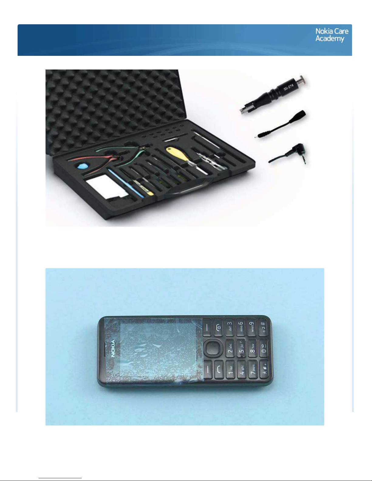
For disassembling you need the Nokia Standard toolkit version 2. You will also need an AV plug, a DC plug
and the camera removal tool SS-276.
Note that the disassembly instructions are made witht the dual SIM variant (RM-872).
Protect the A-COVER with protective film.
Page 4

Release the B-COVER by using the release notch on the bottom of the device.
Remove the B-COVER.
Page 5
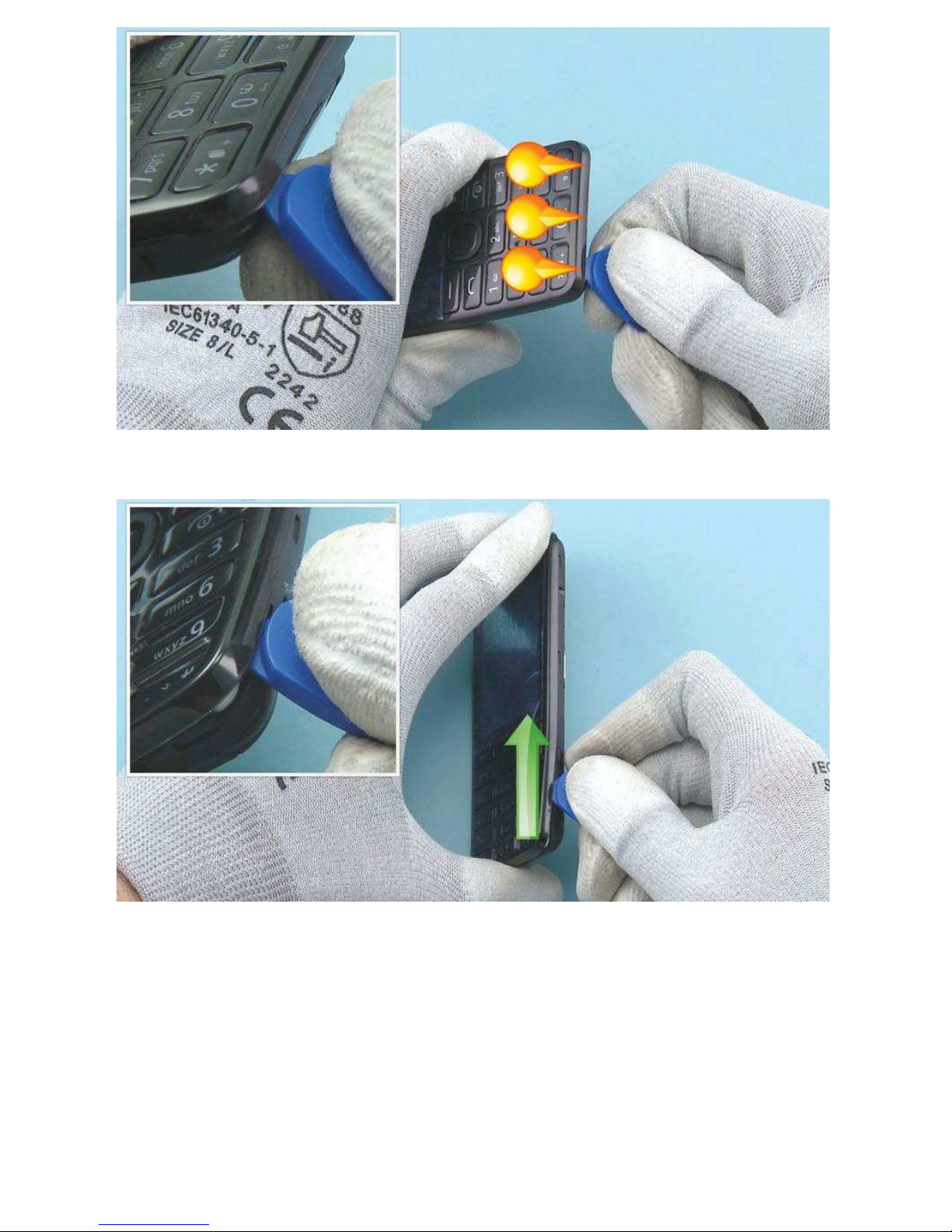
To remove the A-COVER, first release the clips from the bottom of the device with the SRT-6.
Then release the clips from the right side by sliding the SRT-6 along the side.
Page 6

Then release the clips from the left side by sliding the SRT-6 along the side.
Then release the top side.
Page 7
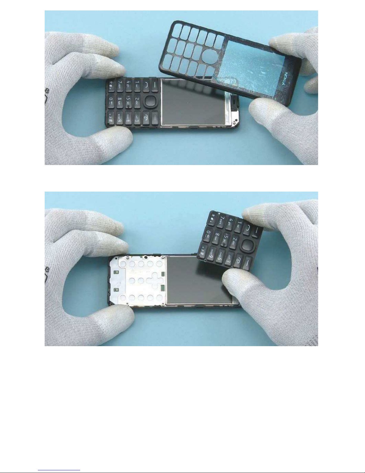
Remove the A-COVER.
Remove the KEYMAT.
Page 8

Protect the DISPLAY with protective film.
Unscrew the six Torx+ size 6 screws in the order shown.
Page 9

To remove the ENGINE BOARD, release the three shown clips with the SS-93.
Lift up and remove the ENGINE BOARD.
Page 10

Open the DISPLAY connector with the SS-93. Be careful not to damage the connector or any
components nearby.
To remove the UI SHIELDING, release the two clips from the shown side.
Page 11

Release also the two clips from the other side.
Lift up and remove the UI SHIELDING.
Page 12

Remove the DISPLAY.
Place the SS-276 camera removal tool on top of the CAMERA and press down until the CAMERA retaining
clips are released. Then hold down the button on top of the SS-276...
Page 13

...And lift up the CAMERA.
Release one corner of the DOMESHEET with the dental tool. Be careful not to injure yourself with the
sharp end of the dental tool. Peel off the DOMESHEET with tweezers. Do not use it again. Discard it.
Page 14

Release the AV JACK with an AV plug and remove it with tweezers.
Release the DC JACK with a DC plug and remove it.
Page 15

Release the EARPIECE with the dental tool.
Remove the EARPIECE with tweezers. Do not use it again. Discard it.
Page 16

If the EARPIECE adhesive remains in the D-COVER, peel it off.
Release the 3 IN 1 SPEAKER with the dental tool and remove it with tweezers.
Page 17

Peel off the GASKET on top of the SPEAKER. Do not use it again. Discard it.
To remove the ANTENNA MODULE, use the SRT-6 to push down the shown clip.
Page 18

Then release the ANTENNA MODULE from the side and top witht the SRT-6.
Remove the ANTENNA MODULE.
Page 19

The Nokia 206 Dual SIM disassembly procedure is complete.
-END OF DISASSEMBLY-
©2012 Nokia | Nokia Internal Use only | All Rights Reserved.
Page 20

Service Manual Level 1 and 2
Nokia 206 Dual SIM/2060, Nokia 20
6
RM-872, RM-873
V
ersion 1.
0
Assembly hints
Fasten the six Torx+ size 6 screws in the order shown to the torque of 15 Ncm.
©2012 Nokia | Nokia Internal Use only | All Rights Reserved.
Page 21

Service Manual Level 1 and 2
Nokia 206 Dual SIM/2060, Nokia 206
RM-872, RM-873
Version 1.0
Solder components
V2403
F2051
X7454
V2404
X7453
LED
LED
Charger
fuse
Antenna
GND spring
Antenna
spring
BOTTOM
v1.0
©2012 Nokia | Nokia Internal Use Only | All Rights Reserved.
Page 22

Service Manual Level 1 and 2
Nokia 206 Dual SIM/2060, Nokia 20
6
RM-872, RM-873
V
ersion 1.
0
Service devices
CA-101 Service cable AC-11 Travel charger SS-276 Camera removal tool
BL-4U Flash Adapter SF-299R
Nokia Standard Toolkit (v2)
For more information, refer to the Service
Bulletin (SB-011) on Nokia Online. Supplier
or manufacturer contacts for tool re-order
can be found in “Recommended service
equipment” document on Nokia Online.
©2012 Nokia | Nokia Internal Use only | All Rights Reserved.
Page 23

Service Manual Level 1 and 2
Nokia 206 Dual SIM/2060, Nokia 206
RM-872, RM-873
Version 1.0
Product controls and interfaces
2
3
4
5
6
1
15
16
7
89
10
11
12
14
13
14 — SIM Card slot (Dual SIM)
15 — Loudspeaker
16 — Antenna area
9 — Power/End key
8 — Call key
7 — Right selection key
6 — Left selection key
5 — Scroll key
4 — Display
3 — Earpiece
2 — Nokia AV 3.5 mm connector
1 — Charger connector
10 — Alphanumeric keypad
11 — Microphone
12 — Battery cover release notch
13 — Camera
v1.0
©2012 Nokia | Nokia Internal Use only | All Rights Reserved.
Page 24

Service Manual Level 1 and 2
Nokia 206 Dual SIM/2060, Nokia 206
RM-872, RM-873
Version 1.0
Service concept
Flashing concept
Transceiver
Product specific
flash adapter
Service
software
CA-101
©2012 Nokia | Nokia Internal Use only | All Rights Reserved.
Page 25

Service Manual Level 1 and 2
Nokia 206 Dual SIM/2060, Nokia 206
RM-872, RM-873
V
ersion 1.
0
Version history
Version Date Description
1.0 07.12.2012 First published version
©2012 Nokia | Nokia Internal Use only | All Rights Reserved.
Page 26

 Loading...