

Page 1
Service Manual for L1 and L2
z
z
z
z
Nokia Asha 205 / 2050
Dual SIM
Nokia Asha 205
RM-862, RM-863, RM-864
Key features
QWERTY keyboard
Nokia Xpress Browser
EA Games Gift - download free games from EA
Easy content sharing with Nokia Slam
Version 1.0
Check the repair
policy before
performing any
mechanical repair
on Service Level
1&2!
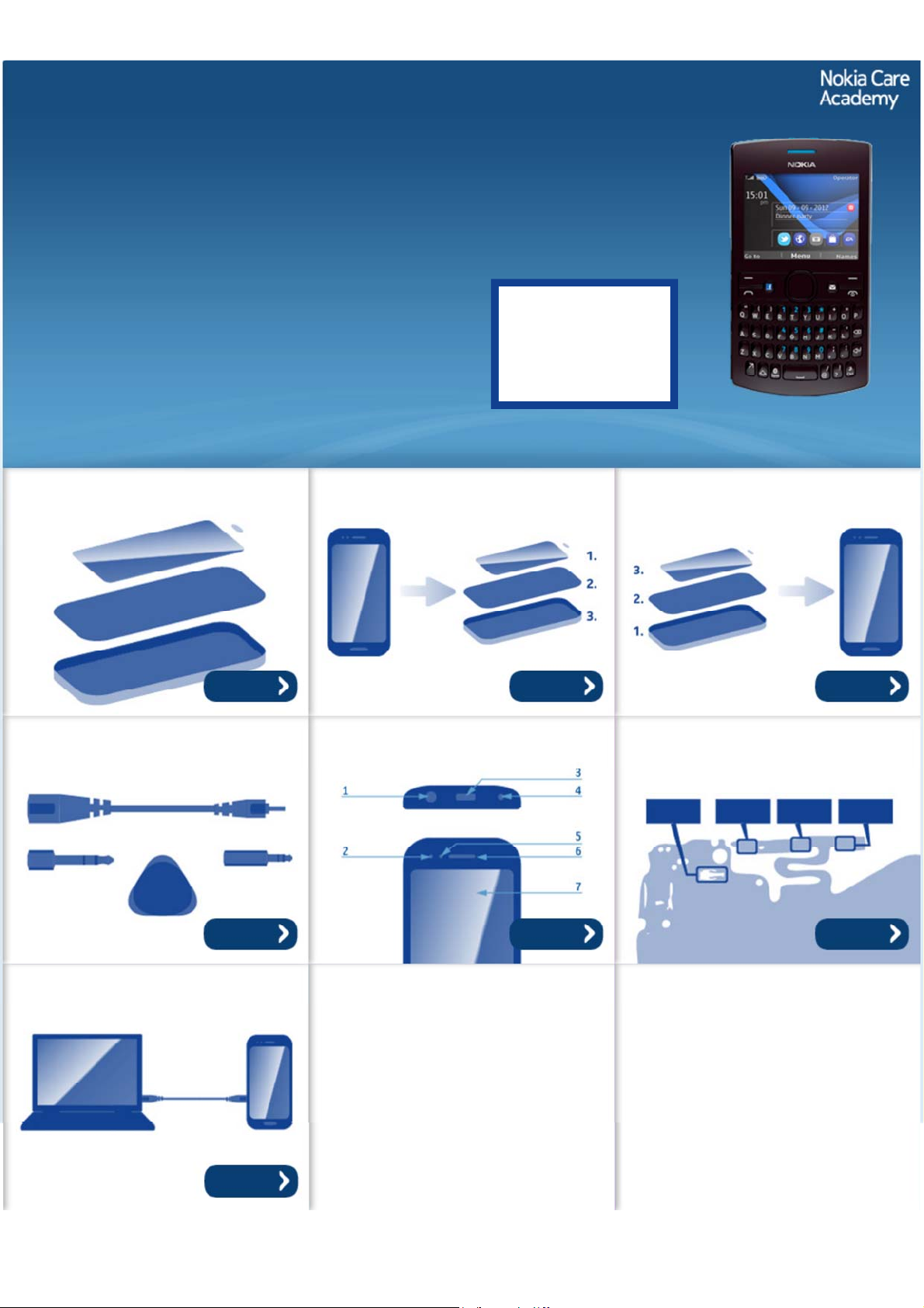
Exploded view Disassembly steps Assembly hints
More More More
Service devices Product controls and interfaces Solder components
Service concept
More More More
More
©2012 Nokia | Nokia Internal Use only | All Rights Reserved.
Page 2
Service Manual Level 1 and 2
Nokia Asha 205 Dual SIM / 2050
Nokia Asha 205
RM-862, RM-863, RM-864
Version 1.0
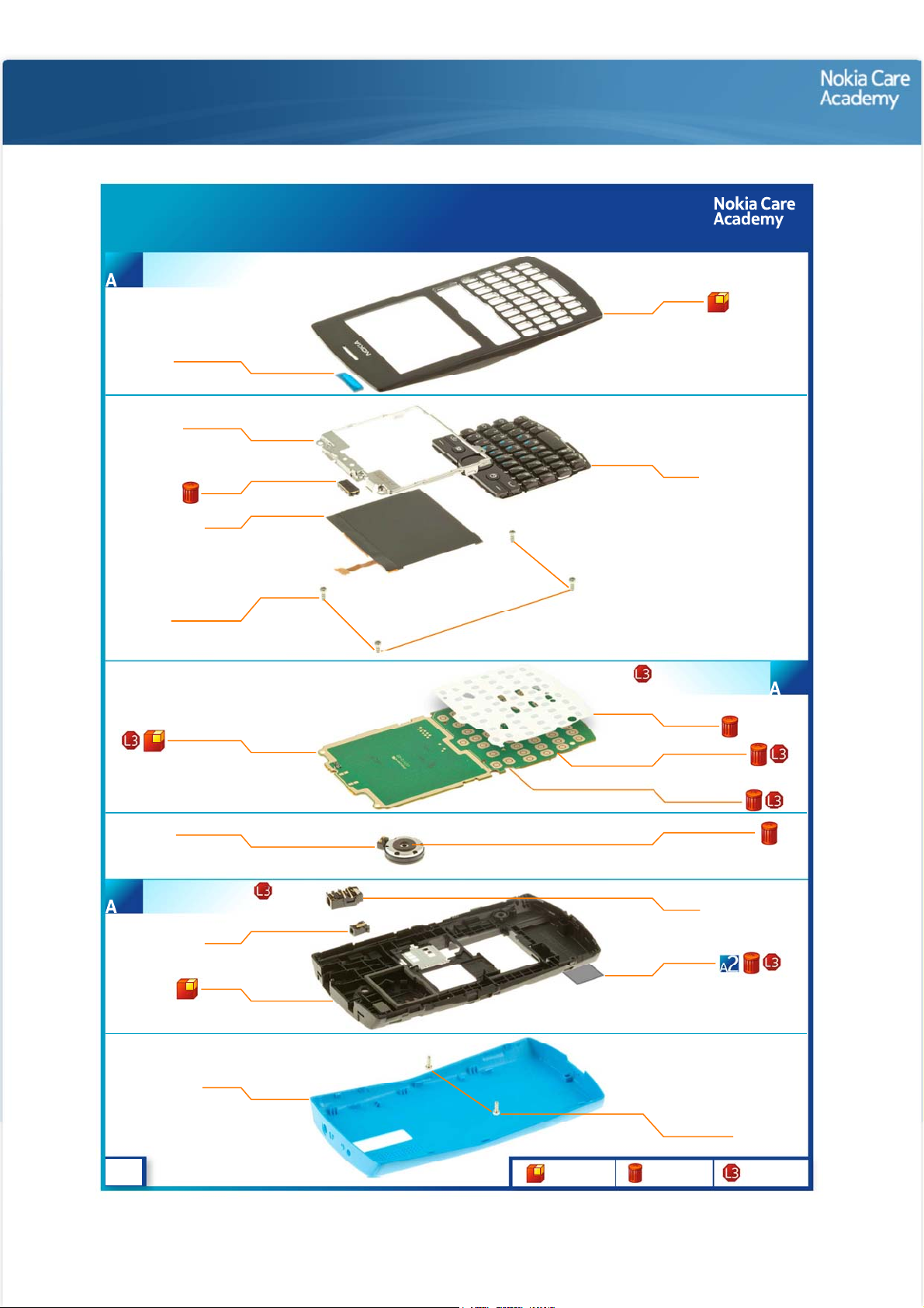
Exploded view
Nokia Asha 205
RM-863, RM-864
A-COVER ASSEMBLY
(I0001, I0002)
1
EARPIECE MESH
I0002
UI SHIELDING
I0005
EARPIECE
I0006
DISPLAY
I0007
SCREW TORX+
SIZE 6 M1.6x4.5
I0004
Exploded view
A-COVER
I0001
KEYMAT
I0003
LIGHT SWAP PWB
D-COVER ASSEMBLY
(I0013 - I0015)
3
v1.0
I0008
3 IN 1 SPEAKER
I0016
DC JACK
I0014
D-COVER
I0015
B-COVER
I0019
Only available
as assembly
LIGHT SWAP PACKAGE
Not reuseable
after removal
(I0008 - I0012)
DOMESHEET
I0009
FEM SHIELDING LID
I0011
BB SHIELDING LID
I0010
GASKET ON SPEAKER
I0017
AV JACK
I0013
TYPE LABEL
I0012
SCREW TORX+
SIZE 6 M1.6x4.5
I0018
2
Repair/swap
only in level 3
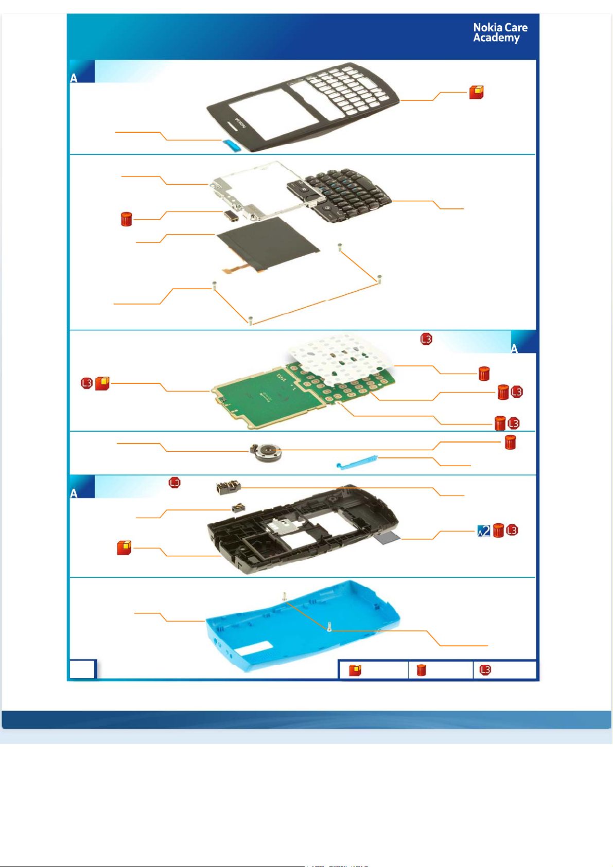
Page 3
Nokia Asha 205 Dual SIM / 2050
RM-862
A-COVER ASSEMBLY
(I0001, I0002)
1
EARPIECE MESH
I0002
UI SHIELDING
I0005
EARPIECE
I0006
DISPLAY
I0007
SCREW TORX+
SIZE 6 M1.6x4.5
I0004
Exploded view
A-COVER
I0001
KEYMAT
I0003
LIGHT SWAP PWB
D-COVER ASSEMBLY
(I0013 - I0015)
3
v1.0
I0008
3 IN 1 SPEAKER
I0016
DC JACK
I0014
D-COVER
I0015
B-COVER
I0020
Only available
as assembly
LIGHT SWAP PACKAGE
Not reuseable
after removal
(I0008 - I0012)
DOMESHEET
I0009
FEM SHIELDING LID
I0011
BB SHIELDING LID
I0010
GASKET ON SPEAKER
I0017
SIM DOOR
I0018
AV JACK
I0013
TYPE LABEL
I0012
SCREW TORX+
SIZE 6 M1.6x4.5
I0019
2
Repair/swap
only in level 3
©2012 Nokia | Nokia Internal Use only | All Rights Reserved.
Page 4
Service Manual Level 1 and 2
Nokia Asha 205 / 2050
RM- 862, RM-863, RM-864
Version 1.0
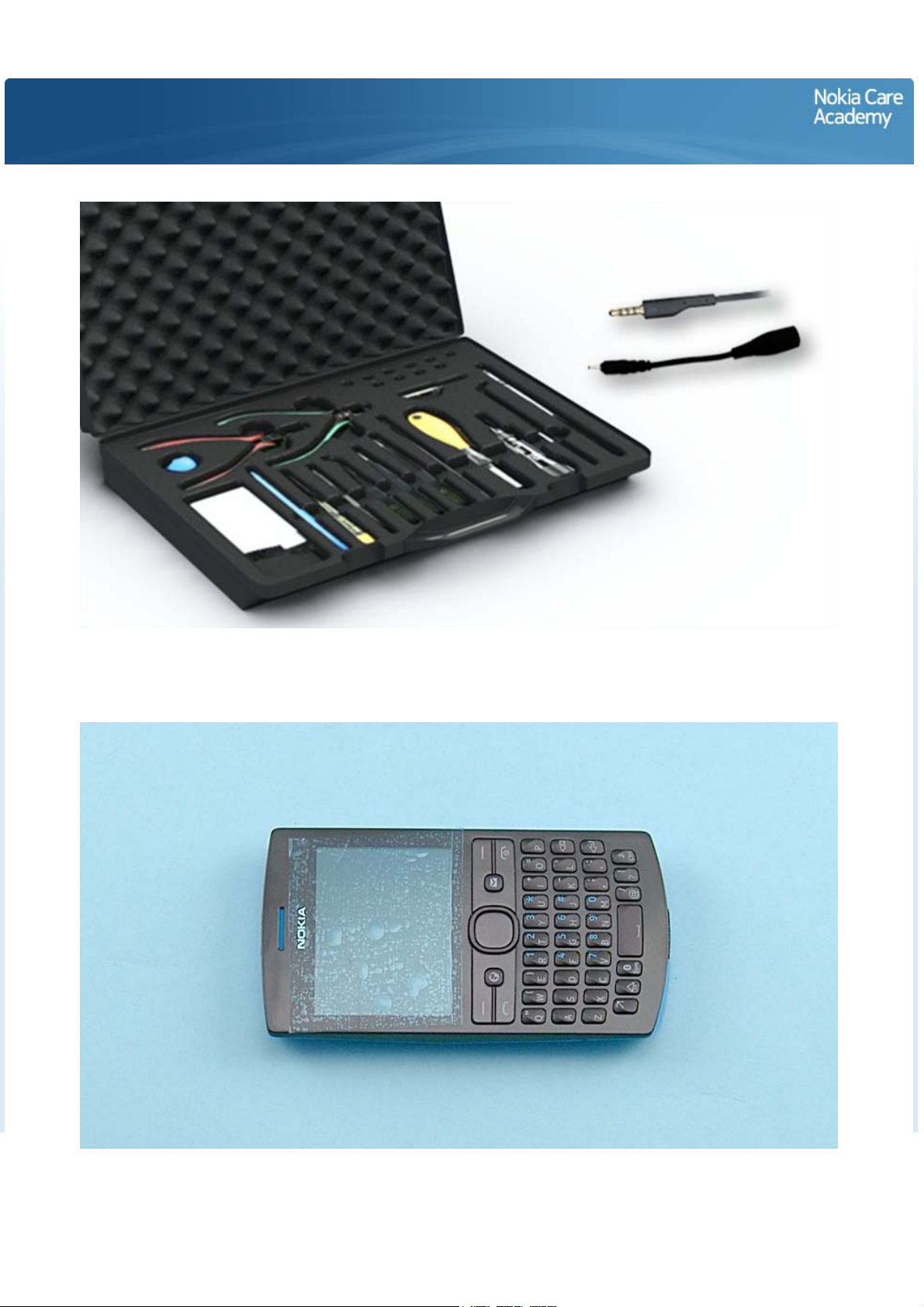
Disassembly steps
For disassembling you need the Nokia Standard toolkit version 2. You will also need a DC plug and an AV
plug. Note that the disassembly instructions are made with the dual SIM variant (RM-862).
Protect the A-COVER with protective film.
Page 5
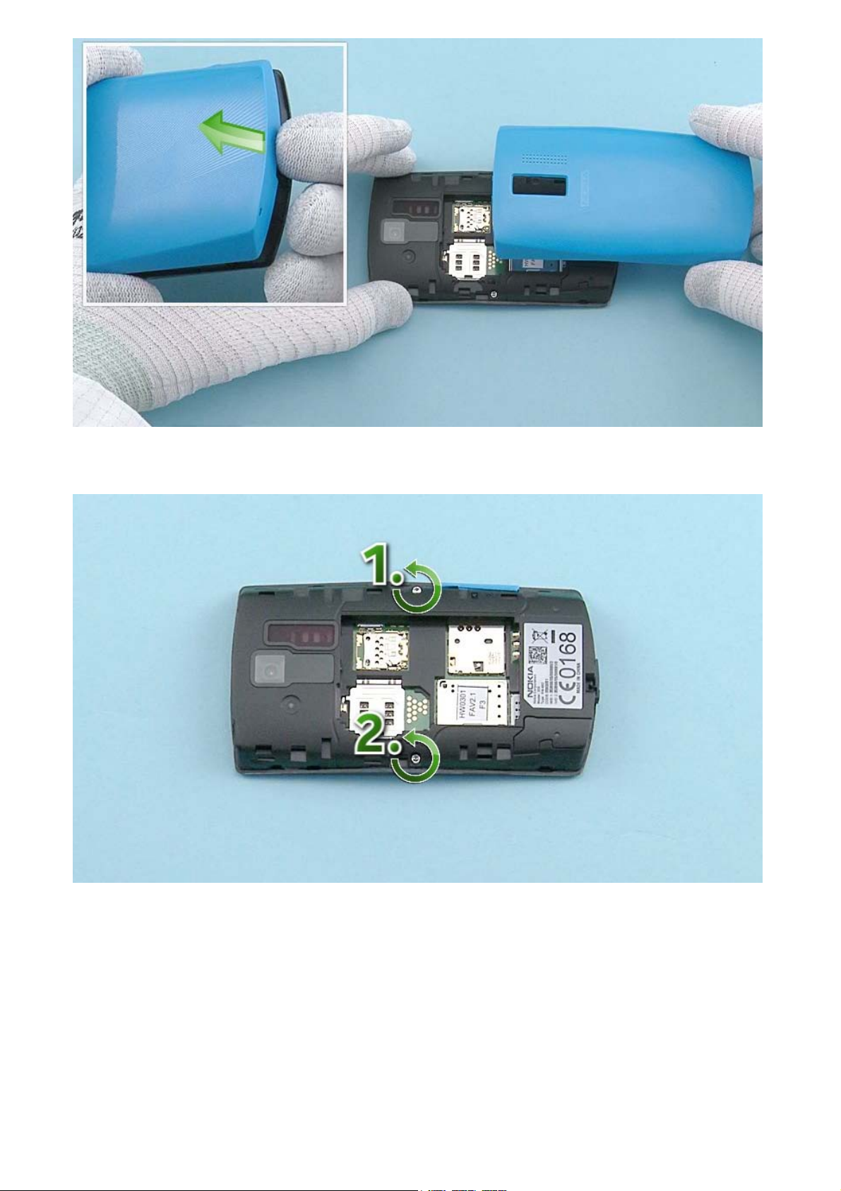
Lift up the B-COVER from the shown place. Remove the B-COVER.
Unscrew the two Torx+ size 6 screws in the order shown.
Page 6

Start to release the A-COVER with the SRT-6 from the top left side of the device. Work towards the
bottom end with the SRT-6 and open the shown clips holding the A-COVER.
Continue releasing the A-COVER from the top right side of the device. Open all the shown clips on the
right side with the SRT-6.
Page 7
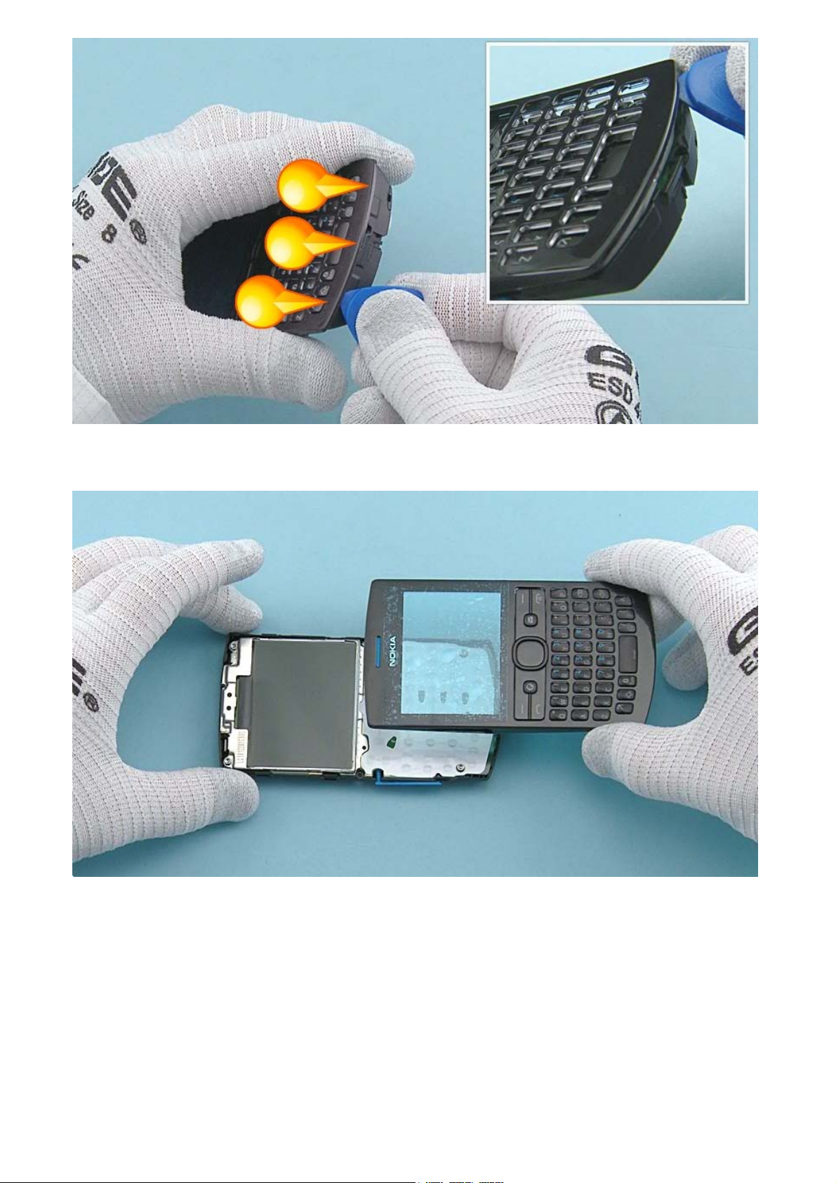
Finally open the three clips on the bottom end.
The A-COVER can now be separated.
Page 8
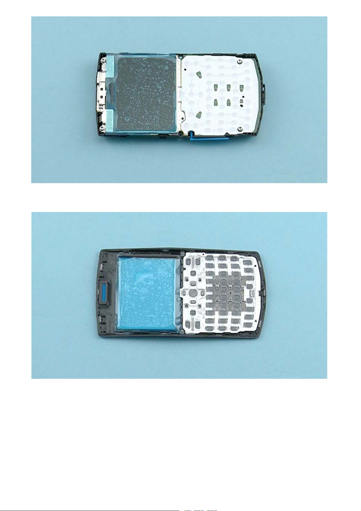
Protect the DISPLAY with protective film.
Protect also the other side of the A-COVER window.
Page 9

Use the SRT-6 to open the four clips holding the KEYMAT.
Remove the KEYMAT.
Page 10

Release the EARPIECE MESH with the dental tool. Be careful not to injure yourself with the sharp end of
the dental tool. Remove the EARPIECE MESH with tweezers.
Unscrew the four Torx+ size 6 screws in the order shown.
Page 11

Lever up the ENGINE BOARD with the SS-93 from the shown place.
The ENGINE BOARD can now be separated from the D-COVER.
Page 12

Open the SIM DOOR and remove it by pulling it up. Note that this step applies only with the dual SIM
variant (RM-862).
Lever up the 3 IN 1 SPEAKER with the sharp end of the SS-93. Remove the 3 IN 1 SPEAKER with tweezers.
Page 13

Use the dental tool to release the GASKET ON SPEAKER. Remove the GASKET ON SPEAKER and discard it.
Use an AV plug to lift up and remove the AV JACK.
Page 14

Use a DC plug to lift up and remove the DC JACK.
Use the SS-93 to open the three clips holding the UI SHIELDING.
Page 15

Open the DISPLAY connector. Be careful not to damage the connector or any components nearby.
The DISPLAY and the UI SHIELDING can now be separated from the ENGINE BOARD.
Page 16

Push the DISPLAY out from the UI SHIELDING. Remove the DISPLAY.
Release the EARPIECE with the SS-93. Remove it with tweezers. Do not use it again. Discard it.
Page 17

Release one corner of the DOMESHEET with the dental tool. Peel it off and remove it. The DOMESHEET is
not reusable. Discard it.
The Nokia Asha 205 Dual SIM / 2050 disassembly procedure is complete.
-END OF DISASSEMBLY-
©2012 Nokia | Nokia Internal Use only | All Rights Reserved.
Page 18

Service Manual Level 1 and 2
Nokia Asha 205 / 2050
RM- 862, RM-863, RM-864
Version 1.0
Assembly steps
Place the top end of the DISPLAY to the UI SHIELDING first. Gently press the DISPLAY to its place.
Align the ENGINE BOARD to the UI SHIELDING by using the two shown screw holes.
Page 19

Press the ENGINE BOARD so that the three shown clips of the UI SHIELDING are attached to the ENGINE
BOARD.
Connect the DISPLAY connector with the SS-93. Be careful not to damage the connector or any nearby
components.
Page 20

Fasten the four Torx+ size 6 screws to the torque of 19 Ncm in the order shown.
Fasten the two Torx+ size 6 screws to the torque of 17 Ncm in the order shown.
©2012 Nokia | Nokia Internal Use only | All Rights Reserved.
Page 21

Service Manual Level 1 and 2
V
0
Nokia Asha 205 / 2050
RM-862, RM-863, RM-864
ersion 1.
Service devices
CA-101 Service cable AC-11 Travel charger
AC-8C & CA-187C for China
SF-291 Flash Adapter Nokia Standard Toolkit (v2)
For more information, refer to the Service
Bulletin (SB-011) on Nokia Online. Supplier or
manufacturer contacts for tool re-order can be
found in “Recommended service equipment”
document on Nokia Online.
BL-5C Battery
©2012 Nokia | Nokia Internal Use only | All Rights Reserved.
Page 22

Service Manual Level 1 and 2
Nokia Asha 205 / 2050
RM-862, RM-863, RM-864
Version 1.0
Product controls and interfaces
2
6
8
10
13
11
12
14
1
3
4
5
7
9
1 — Nokia AV 3.5mm connector
2 — Charger connector
3 — Earpiece
4 — Display
5 — Navigation key
6 — Left selection key
7 — Right selection key
8 — Call key
9 — End/Power key
10 — Left shortcut key
11 — Right shortcut key
12 — Keyboard
13 — Strap holder
14 — Microphone
15 — Camera
16 — Loudspeaker
17 — SIM card slot (SIM 2)
Only in dual SIM (RM-862) variant!
18 — Antenna area
Ver. 1.0
15
16
17
18
©2012 Nokia | Nokia Internal Use only | All Rights Reserved.
Page 23

Service Manual Level 1 and 2
Nokia Asha 205 / 2050
RM-862, RM-863, RM-864
Version 1.0
Solder components
V2422
V2421
Keyboard
LED
Keyboard
LEDLED
V2424
V2423
Keyboard
LED
Keyboard
LED
V2426
V2425
Keyboard
LED
Keyboard
LED
V2428
V2427
Keyboard
LED
BOTTOM
Charger
fuse
F2051
v1.0
G2200
Back-up
battery
E2750
Grounding
Spring
©2012 Nokia | Nokia Internal Use Only | All Rights Reserved.
Page 24

Service Manual Level 1 and 2
Nokia Asha 205 / 2050
RM-862, RM-863, RM-864
Version 1.0
Flashing concept
Service concept
Service
software
CA-101
Product specific
flash adapter
Transceiver
©2012 Nokia | Nokia Internal Use only | All Rights Reserved.
Page 25

Service Manual Level 1 and 2
V
y
Nokia Asha 205 Dual SIM / 2050
RM-862, RM-863, RM-864
ersion 1.0
Version Date Description
1.0 27.11.2012 First published version
Version histor
©2012 Nokia | Nokia Internal Use only | All Rights Reserved.
 Loading...