

Page 1

TRANSCEIVER
NHK–3
11/97 OJ
Technical Documentation
Contents of Transceiver
Transceiver NHK–3 7–2
Introduction 7–2
Functional Description 7–2
Interconnection Diagram 7–3
Exploded View of NHK–3XN 7–4
Assembly Parts of NHK–3XN 7–5
Exploded View of NHK–3XA 7–6
Assembly Parts of NHK–3XA 7–7
Exploded View of NHK–3XB 7–8
Assembly Parts of NHK–3XB 7–9
Exploded View of NHK–3XT 7–10
Assembly Parts of NHK–3XT 7–11
7–1
Copyright Nokia Mobile Phones
Page 2

TRANSCEIVER
NHK–3
Transceiver NHK–3
Related Documentation
Introduction
The NHK–3 is a radio transceiver unit for the Pan–European PCN network. It is
PCN power class 4 transceiver providing 11 power levels at a maximum power
of 1 W. The standard is defined together by all related parties in the European
Telecommunications Standard Institute, ETSI.
11/97 OJ
Technical Documentation
0260346 Mechanics of NHK–3XN
0260347 Mechanics of NHK–3XA
0260348 Mechanics of NHK–3XB
0261065 Mechanics of NHK–3XT
0260521 Mechanics of NHK–3XP
7–2
Copyright Nokia Mobile Phones
The transceiver consists of three modules: system module, user interface module and mechanics.
The plug–in SIM (Subscriber Identity Module) card reader is located inside the
phone.
Functional Description
The transceiver electronics consist of radio module (system + RF blocks) and
UIF module. UIF module is connected to radio module with a connector. System blocks and RF blocks are interconnected with PCB wirings. Transceiver
can be connected to accessories with a bottom system connector, which includes charging and accessory control.
The system blocks provides MCU and DSP environments, logic control IC
(EDSA), memories, audio processing and RF control hardware (RFI). On board
power supply circuitry delivers operating voltage for both system and RF
blocks.
The general purpose microcontroller, Hitachi H8, communicates with DSP, memories and logic control IC (EDSA) with 8 bit data bus.
RF block is designed for a handportable phone; which operates in GSM system. Purpose of the RF block is to receive and demodulate radio frequency signal from the base station and to transmit a modulated RF signal to the base
station.
Page 3
TRANSCEIVER
NHK–3
11/97 OJ
Technical Documentation
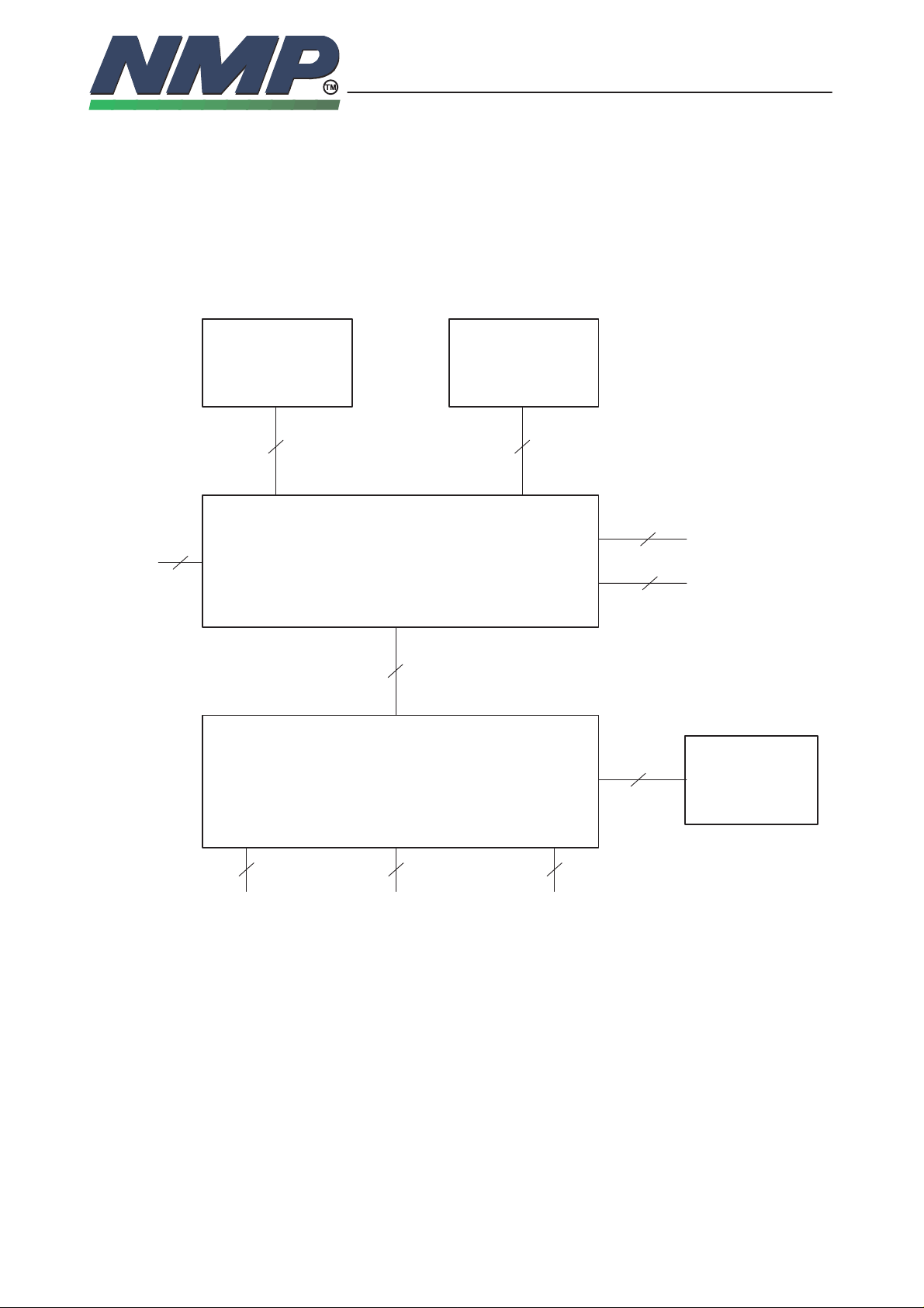
Interconnection Diagram
SIM Display
524
2
MIC
UI – MODULE
7–3
Copyright Nokia Mobile Phones
2
EARPIECE
2
BUZZER
RADIO – MODULE
16 2+2 2
SYSTEM
CONNECTOR
30
4
BATTERY
CHARGER ANTENNA
Page 4
TRANSCEIVER
NHK–3
11/97 OJ
Technical Documentation
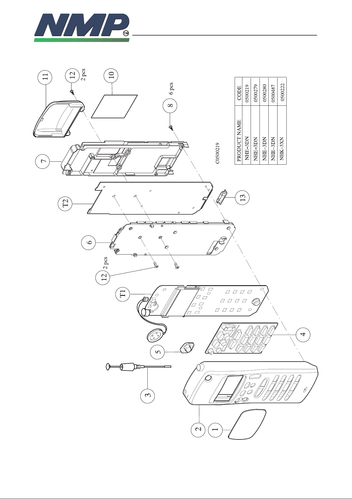
Exploded View of NHK–3XN
7–4
Copyright Nokia Mobile Phones
update:08.05.1995
Page 5

TRANSCEIVER
NHK–3
11/97 OJ
Technical Documentation
Copyright Nokia Mobile Phones
Assembly Parts of NHK–3XN
ITEM Q’TY CODE DESCRIPTION VALUE, TYPE
1 9457141 Display window 4C 24313 (Nokia 2040)
2 9450450 Front cover light grey 2C 23888 (Nokia 2040)
3 0660095 Antenna JTI/PCN 1710–1880 MHz
4 9790098 Keypad 4C 24005
5 9790091 Power keypad 4C 24017
6 9457207 Shield 1D 25161
7 9540007 Chassis 1D 24941
8 6 6290041 PT screw 1.8–0.8x8 h=0.9 Tx6
10 9380115 Type label (print. Finland 4D 24402)
(Nokia 2040)
10 9380115 Type label (print. Germany 4D 24486) (Nokia 2040)
11 9450360 Back cover 1D 23873
12 4 6290060 Screw M2x5 Torx 6
13 9457112 Connector cover 3D 23772
T1 0200604 System module GS9M
T2 0200564 UIF module GU1MN
9480198 Protection tape 4D 25314
(Nokia 2040)
7–5
Page 6

TRANSCEIVER
NHK–3
11/97 OJ
Technical Documentation
Exploded View of NHK–3XA, XP
7–6
Copyright Nokia Mobile Phones
update: 08.05.1995
Page 7

TRANSCEIVER
NHK–3
11/97 OJ
Technical Documentation
Copyright Nokia Mobile Phones
Assembly Parts of NHK–3XA, XP
ITEM Q’TY CODE DESCRIPTION VALUE, TYPE
1 9457167 Display window 4C 24748 (Nokia 2042)
1 9457187 Display window 4C 24954 (Philips)
2 9457145 Front cover 2C 24364 (Nokia 2042)
2 9450490 Front cover 2C 25165 (Philips)
3 0660095 Antenna JTI/PCN 1710–1880 MHz
4 9790096 Keypad 4C 24007
4 9790123 Keypad 4C 24810 (Philips)
5 9457207 Shield 1D 25161
6 9540007 Chassis 1D 24941
7 6 6290041 PT screw 1.8–0.8x8 h=0,9 Tx6
9 9380115 Type label (print. Finland 4D 24403)
(Nokia 2042)
9 9380115 Type label (print. Germany 4D 24487) (Nokia 2042)
9 9380115 Type label (print. Germany 4D 21663) (Philips)
10 9457257 Back cover 1D 24809
11 4 6290060 Screw M2x5 Torx 6
12 9457112 Connector cover 3D 23772
T1 0200604 System module GS9M
T2 0200565 UIF module GU1MT
9480198 Protection tape 4D 25314
(Nokia 2042)
7–7
Page 8

TRANSCEIVER
NHK–3
11/97 OJ
Technical Documentation
Exploded View of NHK–3XB
7–8
Copyright Nokia Mobile Phones
update: 08.05.1995
Page 9

TRANSCEIVER
NHK–3
11/97 OJ
Technical Documentation
Copyright Nokia Mobile Phones
Assembly Parts of NHK–3XB
ITEM Q’TY CODE DESCRIPTION VALUE, TYPE
1 9450446 Display window 4C 24345 (Nokia 2046)
2 9450417 Front cover 2C 24223 (Nokia 2046)
3 0660095 Antenna JTI/PCN 1710–1880 MHz
4 9790094 Keypad 4C 24009
5 9457207 Shield 1D 25161
6 9540007 Chassis 1D 24941
7 6 6290041 PT screw 1.8–0.8x8 h=0.9 Tx6
9 9380115 Type label (print. Finland 4D 24404)
9 9380115 Type label (print. Germany 4D 24488) (Nokia 2046)
10 9457257 Back cover 1D 24809
11 4 6290060 Screw M2x5 Torx 6
12 9457112 Connector cover 3D 23772
T1 0200604 System module GS9M
T2 0200565 UIF module GU1MT
9480198 Protection tape 4D 25314
(Nokia 2046)
7–9
Page 10

TRANSCEIVER
NHK–3
11/97 OJ
Technical Documentation
Exploded View of NHK–3XT
7–10
Copyright Nokia Mobile Phones
update:08.05.1995
Page 11

TRANSCEIVER
NHK–3
11/97 OJ
Technical Documentation
Copyright Nokia Mobile Phones
Assembly Parts of NHK–3XT
ITEM Q’TY CODE DESCRIPTION VALUE, TYPE
1 9457141 Display window 4C 24313 (Nokia 2040)
2 9450450 Front cover, light grey 2C 23888 (Nokia 2040)
2 9450??? Front cover, red 2C 23888 (Nokia 2040)
2 9457627 Front cover, yellow 2C 23888 (Nokia 2040)
2 9450??? Front cover, blue 2C 23888 (Nokia 2040)
2 9450??? Front cover, green 2C 23888 (Nokia 2040)
3 0660095 Antenna JTI/PCN 1710–1880 MHz
4 9790098 Keypad 4C 24005
5 9790091 Power keypad 4C 24017
6 9457207 Shield 1D 25161
7 9540007 Chassis 1D 24941
8 6 6291662 PT screw 1.8x8 FeZn Torx 6
10 9380115 Type label (print. Finland 4D ?????)
10 9380115 Type label (print. Germany 4D ?????) (Nokia 2040)
11 9457257 Back cover 1D 24809
12 4 6290060 Screw M2x5 Torx 6
13 9457112 Connector cover 3D 23772
T1 0200604 System module GS9M
T2 0200564 UIF module GU1MN
9480198 Protection tape 4D 25314
(Nokia 2040)
7–11
Page 12

TRANSCEIVER
NHK–3
11/97 OJ
Technical Documentation
7–12
Copyright Nokia Mobile Phones
This page intentionally left blank.
 Loading...