

Page 1

TUNING INSTRUCTIONS
NHE–3
Contents
Tuning Instructions 6–3–2
General 6–3–2
Required Equipment 6–3–3
Equipment Setup 6–3–3
Equipment Setup For Tuning A Phone Without Remowing Covers 6–3–4
Equipment Setup For Tuning A Phone With Remowing Covers 6–3–5
Starting The Program 6–3–6
Starting options for PCLocals service software 6–3–6
Tuning Steps 6–3–7
1. RSSI Reference Signal Level Storage 6–3–7
2. AFC Diagram Storage 6–3–7
3. I/Q Modulator Amplitude Balance and Phase Shift Tuning 6–3–8
4. Tuning of Transmitter Power Levels 6–3–10
5. Charge Voltage Adjustment 6–3–11
6. Battery Voltage Adjustment 6–3–11
9546HK
Technical Documentation
6–3–1
Copyright Nokia Mobile Phones
DRAFT
Page 2

TUNING INSTRUCTIONS
NHE–3
Tuning Instructions
General
In contrast to earlier second–generation analog cellular phones almost all tuning operations of the NHE–3 are carried out using the PCLocals software. The
PCLocals program turns the phone into the Locals mode, in which the phone
can be outwardly controlled via the M2BUS interface.
Tuning is based on the PCLocals software communicating with the D/A and A/D
converters of the phone. In some instances the phone processor will also calculate the required correction parameter.
The tuning values of the phone reside on the EEPROM. The contents of the
EEPROM can be read by the PCLocals program and saved as a file. This is advisable when there is need to retain that information, e.g. in view of replacement of the circuit. The program also enables writing the default parameters on
the EEPROM, in which case all tuning steps should be carried out.
9546HK
Technical Documentation
6–3–2
Copyright Nokia Mobile Phones
N.B. During tuning, proceed as follows:
– Take care not to damage sensitive measuring instruments with excessive
RF power.
– Carry out all tuning steps in the shortest possible time to avoid excessive
heating of RF units.
– Perform all tuning steps in the order presented.
– Never try to mask a fault by tuning it out!
DRAFT
Page 3

TUNING INSTRUCTIONS
NHE–3
Required Equipment
– PC/AT computer with PCLocals software; see Sect. 5 for intructions on
installation and use.
– M2BUS adapter DAU–2 and other service accessories; see equipment set-
up pictures.
– Multimeter or DVM.
– GSM radio telephone test station or separate measuring equipment as fol-
lows:
– frequency counter (±1 ppm)
– RF generator
– pulse power meter
– spectrum analyzer
– attenuator and branching unit
9546HK
Technical Documentation
6–3–3
Copyright Nokia Mobile Phones
Equipment Setup
To set up the equipment, connect the M2BUS adapter to the serial port
(RS–232) of the computer. In case you are using a 9–pin serial port (normal
with an AT set) use the mating adapter supplied with the M2BUS adapter. Turn
off the computer before connecting to avoid possible damage to the serial port.
Attach one end of the XCM–1 modular cable to the DAU–2 PC/M2BUS adapter
and the other end to the JBS–7 service box. Use suitable adapter, SCS–1 service cable when the covers of the phone are in place, JBS–8 test frame with the
phone covers off, and attach it to the phone. Then connect it to the service box.
DRAFT
Page 4
TUNING INSTRUCTIONS
NHE–3
9546HK
Technical Documentation
Copyright Nokia Mobile Phones
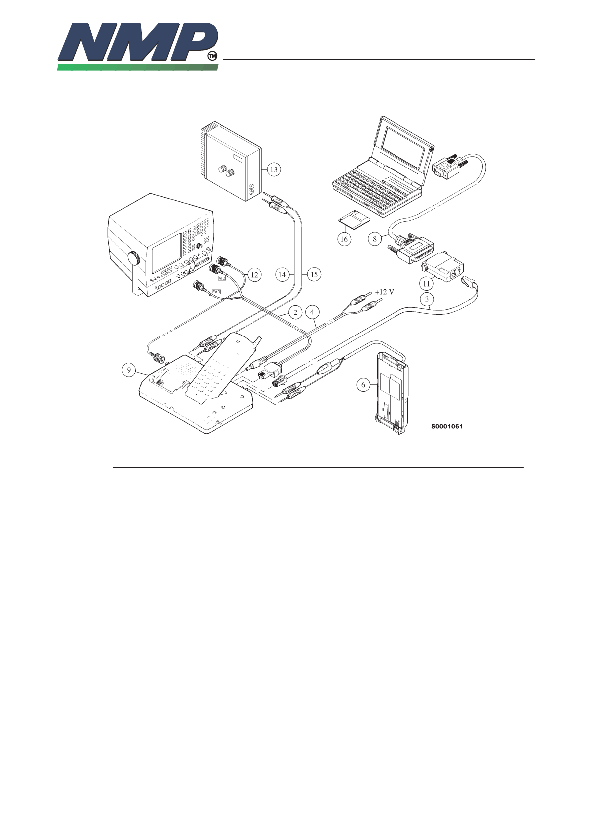
Equipment Setup For Tuning A Phone Without Remowing Covers
6–3–4
Item: Service accessory: Product code:
2 Audio cable, ADS–1 0730011
3 Modular cable, XCM–1 4626131
4 Power connector, PCS–1 0730012
6 Dummy battery, BTS–9 0770030
8 RS–232 adapter (9 pin to 25 pin) 4626170
9 Service box, JBS–7 0770015
11 PC/M2BUS adapter, DAU–2 0750006
12 BCN cable (not available)
13 Battery tester BT–20 4626146
14 Banana cable (not available)
15 Banana cable (not available)
16 PCLocals diskette 3.5” 0193682
16 PCLocals diskette 5.25” 0193681
17 Software protection key PKD–1 ”dongle” 0750018
DRAFT
Page 5

TUNING INSTRUCTIONS
NHE–3
9546HK
Technical Documentation
Copyright Nokia Mobile Phones
Equipment Setup For Tuning A Phone With Remowing Covers
6–3–5
Item: Service accessory: Product code:
2 Audio cable, ADS–1 0730011
3 Modular cable, XCM–1 4626131
4 Power connector, PCS–1 0730012
7 Test frame, JBS–8 0770014
8 RS–232 adapter (9 pin to 25 pin) 4626170
9 Service box, JBS–7 0770015
11 PC/M2BUS adapter, DAU–2 0750006
16 PCLocals diskette 3.5”, LSE–4K 0193682
16 PCLocals diskette 5.25”, LSE–4L 0193681
17 Modular T–connector 4626134
DRAFT
Page 6

TUNING INSTRUCTIONS
NHE–3
9546HK
Technical Documentation
Starting The Program
The program is delivered on a diskette and is copy protected with a dongle.
The program can also be installed on the hard disk, which is recommendable to
obtain a maximum data access rate. In case you want to store the program to
the hard disk, proceed according to instructions given in PCLocals installation
manual.
The program is started with the command:
NHE3SERV <Enter> (or PCLSTART <Enter>)
The program can be set up work with different serial ports or display types.
Starting options for PCLocals service software
The program is started by entering the following command:
NHE1SERV [–serial port] [–video mode] [–text mode] [–file name]
where:
6–3–6
Copyright Nokia Mobile Phones
[–serial port] = the communication port used for M2BUS
(COM1 or COM2). –c1 or –c2
[–video mode] = video control method (BIOS video or HW
video). –vb or –vh (default)
Note: If PCLocals screen updating is slow,
try change this option.
[–text mode] = screen text mode (CO80, MONO, BW80,
or last mode). –tco80, –tmono, –tbw80 or
–tlast (default)
[–file name] = name of the configuration file. –ffilename
DRAFT
Page 7

TUNING INSTRUCTIONS
NHE–3
9546HK
Technical Documentation
Tuning Steps
1. RSSI Reference Signal Level Storage
Reference value for the received signal strength meter are program tuned.
RSSI reference signal level programming:
– Start the service software and go to ”Main” menu.
– Select ”Phone mode” and select local mode with <Enter> key.
– Select ”Testing and Adjustments” menu and press <Enter>.
– Select ”Adjustments” menu and press <Enter>.
– Connect RF generator to antenna connector at 947.06771 MHz.
– Adjust signal generator level to –55 dBm + cable attenuation.
– Select ”RSSI Calibration” and press <Enter>.
6–3–7
Copyright Nokia Mobile Phones
– RSSI offset value should be within 35...45 dB.
– AGC calibration values should be below ±1.0 dB.
– Press <Esc> key.
– Store the value to the EEPROM with <Y> key.
2. AFC Diagram Storage
This tuning is used to calibrate the automatic frequency control range.
AFC tuning:
– Set RF generator frequency 947.06771 MHz at level –55 dBm.
– Select adjustments menu option ”AFC Diagram” and press <Enter>
– Check that ” Cont mode channel” is 60
– The measurement result should be;
• Low over –22 kHz (< –10 kHz)
• Middle ±1.5 kHz (depends on generator frequency accuracy)
• High below +22 kHz (> 10 kHz)
– Press <Esc> key and store with <Y> key.
DRAFT
Page 8

TUNING INSTRUCTIONS
NHE–3
9546HK
Technical Documentation
Copyright Nokia Mobile Phones
3. I/Q Modulator Amplitude Balance and Phase Shift Tuning
The purpose of this tunig operation is to adjust the I/Q modulator d.c. offsets
and the I/Q modulator amplitude balance and phase shift.
I/Q modulator d.c. offsets, amplitude balance and phase shift tuning:
– Connect spectrum analyzer (with attenuator if needed) to phone antenna
connector.
– Select adjustment menu option ”TX I/Q Tuning” and press <Enter>.
– Check that TX power level is level 5, Cont. mode channel is 60 and TX data
type is 1.
– Adjust spectrum analyzer centre frequency to 902 MHz, Span 200 kHz,
Res BW 10 kHz, Video BW 1 kHz and Sweep time 0.5 s.
–67.71 kHz +67.71 kHz
D.C. offset
tunings:
Set this value
to minimum
CHF
> 30 dB
> 35 dB
6–3–8
Amplitude &
phase difference:
Set this value
to minimum
DRAFT
– Select option ”TX I d.c. offset” and press <Enter>.
– Adjust the level of centre frequency (CHF signal) to minimum by varying D/A
converter value with <+> and <–> keys.
– The amplitude difference between CHF–67.7 kHz and CHF should be
>30 dB.
– When value is OK press <Esc>.
– Select option ”TX Q d.c. offset” and press <Enter>.
– Adjust the level of signal CHF to minimum by varying D/A converter value
with <+> and <–> keys.
– When value is OK press <Esc>.
Page 9

TUNING INSTRUCTIONS
NHE–3
9546HK
Technical Documentation
Copyright Nokia Mobile Phones
6–3–9
– Select option ”TX I and Q d.c. offset” and press <Enter>.
– Adjust the level of signal CHF to minimum by varying D/A converter value
with <+> and <–> keys.
– When value is OK press <Esc>.
– Select option ”Tune Amplitude Difference” and press <Enter>.
– Adjust the level of signal CHF+67.7 kHz (902.06771 MHz) to minimum by
varying D/A converter value with <+> and <–> keys.
– The amplitude difference between CHF+67.7 kHz and CHF–67 kHz should
be >35 dB.
– When value is OK press <Esc>.
– Select option ”Tune Phase Difference” and press <Enter>.
– Adjust the level of signal CHF+67.7 kHz to minimum by varying D/A convert-
er value with <+> and <–> keys.
– When value is OK press <Esc>.
– Press <Esc> key and store new values with <Y> key.
DRAFT
Page 10

TUNING INSTRUCTIONS
NHE–3
9546HK
Technical Documentation
4. Tuning of Transmitter Power Levels
This adjustment loads the power levels of the phone transmitter into the EEPROM. When doing this, a pulse power meter or spectrum analyzer must be
used.
Power levels programming:
– Set power supply voltage to 6.0 V.
– Connect pulse power meter or spectrum analyzer to antenna connector.
– Check that continuous mode channel 60.
– Select adjustments menu option ”TX Power Tuning” and press <Enter>.
– Press <Y>.
– Adjust the power level (levels 5, 13 and 15) with <+> and <–> keys and
change levels with <Up> and <Down> keys.
Power
level
Tuning P
OUT
/dBm
(VB=6.0 V, CH60)
6–3–10
Copyright Nokia Mobile Phones
5 33
tune !
7 29
8 27
9 25
10 23
11 21
12 19
13 17
tune !
14 15
15 13
tune !
– Press <F3> to calculate all other levels.
– Once all TX levels are OK, press <Esc> and store readings in phone EE-
PROM with pressing <Y>.
DRAFT
Page 11

TUNING INSTRUCTIONS
NHE–3
9546HK
Technical Documentation
5. Charge Voltage Adjustment
A reference value for charge voltage is set by using an accurate 6.0 V supply.
Calibration of the charge voltage:
– In case the phone covers are not removed replace the standard battery of
the phone with the dummy battery BTS–9.
– Apply +6 V to VCHARG line.
– Select adjustments menu option ”Charge Voltage Adjustment”.
– Program reads 6 V, A/D reading fed to phone VCHARG line.
– Store charge voltage value to phone EEPROM by pressing <Y>
6. Battery Voltage Adjustment
A reference value for battery are calibrated by using an accurate 6 V supply.
Calibration of the A/D converter channels:
6–3–11
Copyright Nokia Mobile Phones
– In case the phone covers are not removed replace the standard battery
of the phone with the dummy battery BTS–9.
– Apply +6 V to dummy battery.
– Select adjustments menu option ”Battery Voltage Adjustment”.
– Program reads 6 V, A/D reading fed to phone VBAT line.
– Store correct value to phone EEPROM by pressing <Y>
DRAFT
Page 12

TUNING INSTRUCTIONS
NHE–3
9546HK
Technical Documentation
6–3–12
Copyright Nokia Mobile Phones
This page intentionally left blank.
DRAFT
 Loading...