

Page 1

INST ALLATION INSTRUCTIONS
NHE–1/3/4
03/97JR
Technical Documentation
Contents of Installation Instructions
Installation Instructions 4–2
Light Car Kit Installation 4–3
Compact HF Holder Installation 4–4
Product List 4–4
Full Handsfree Car Kit Installation 4–5
Product List 4–5
Mounting Plate and Swivel (MKE–1 and HHS–1) 4–6
Mobile Holder (MBH–6) 4–6
Compact HF Holder (PHF–1) 4–6
Cigarette Lighter Cable (LCP–2) 4–6
Holder Unit (MCH–8) 4–7
Junction Box (HFJ–3) 4–7
Handsfree Mic and Speaker (HFM–4 and HFS–6) 4–7
Power Cable (PCH–4) 4–8
Handset (HSU–1) 4–8
Modular 8 Pin Extension Cable (SCE–4) 4–8
Mobile Holder (MBH–6) and Compact HF Holder (PHF–1) together 4–9
Antenna 4–10
Power Distribution 4–11
Car Radio Muting (XCRM) 4–12
Ignition Sense (IGNS) 4–12
Positioning 4–13
4–1
Copyright Nokia Mobile Phones
Page 2

INST ALLATION INSTRUCTIONS
NHE–1/3/4
03/97JR
Technical Documentation
Installation Instructions
This manual aims to give the required information for installing the handheld
telephone into a vehicle. The guide is not intended to be definitive, because different types and modes of vehicle will require different installation work. The
information given is for general guidance only. Read this instructions carefully in
order to minimize the problems and malfunctions.
The car kit should be installed by an authorized installer. The end user should
never attempt to install the car kit without professional assistance as the install
requires special tools and knowledge. The installer should rely on his or her
own skills and common sense when choosing the locations. The terms of warranty demands that the telephone is installed by an experienced installation facility.
Please refer to the telephone’s users guide for instructions on the telephone’s
operation, care and maintenance, including important safety information.
Note: Read the warnings below before beginning the installation
procedure.
4–2
Copyright Nokia Mobile Phones
WARNINGS
–
– DO NOT SMOKE OR USE OPEN FLAMES WHEN WORKING NEAR THE VEHICLE
– ENSURE THAT ELECTRICAL CABLES, HYDRAULIC LINES AND FUEL LINES ARE
– CHECK THAT NORMAL CONTROL AND OPERATION OF THE VEHICLE IS NOT IM-
– AL THOUGH ELECTRONIC SPEED CONTROL, ABS ANTI–LOCK BRAKE AND FUEL
– THE CAR KIT IS SUITABLE FOR USE ONLY IN VEHICLES WITH A 12 V NEGATIVE
ENSURE THE VEHICLE BA TTERY IS DISCONNECTED BEFORE COMMENCEMENT
OF THE INSTALLATION PROCEDURE, AND THA T IT REMAINS DISCONNECTED
DURING THE PROCEDURE.
FUEL SYSTEM.
NOT DAMAGED DURING INST ALLATION.
PAIRED BY THE INSTALLATION; IN PARTICULAR CHECK THE BRAKES AND STEERING THOROUGHLY .
INJECTION SYSTEMS ARE RELA TIVELY IMMUNE TO MALFUNCTION CAUSED BY
NEARBY RADIO TRANSMISSIONS, SHOULD YOU EXPERIENCE FALSE OPERATION
OF THESE SYSTEMS OR ARE IN ANY DOUBT WHA TSOEVER AS TO THEIR FUNCTIONALITY, PLEASE CONSULT THE VEHICLE DEALER.
EARTH SUPPLY. USE ON OTHER SUPPLY VOLTAGES OR ALTERNATIVE POLARITY
WILL DAMAGE THE EQUIPMENT.
Page 3
INST ALLATION INSTRUCTIONS
NHE–1/3/4
03/97JR
Technical Documentation
Light Car Kit Installation
MOUNTING PLA TE
MKE–1
MOBILE HOLDER
MBH–6
4–3
Copyright Nokia Mobile Phones
SWIVEL MOUNT
HHS–1
CIGARETTE LIGHTER
CHARGER LCH–2
Item: Remarks: Type:
Mobile holder MBH–6
Cigarette lighter charger LCH–2
Mounting plate (w/16 screws) MKE–1
Swivel mount (w/6 screws) HHS–1
Page 4
INST ALLATION INSTRUCTIONS
NHE–1/3/4
03/97JR
Technical Documentation
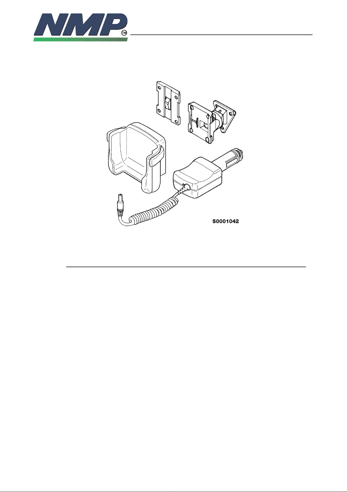
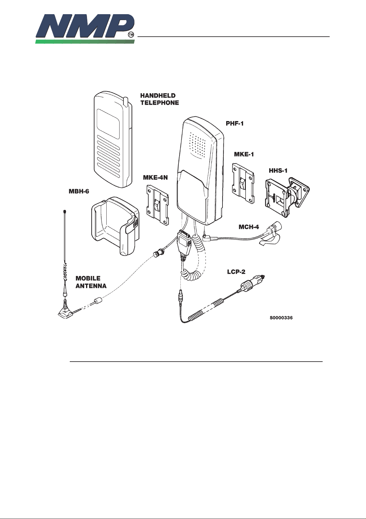
Compact HF Holder Installation
4–4
Copyright Nokia Mobile Phones
Not supplied !
Product List
Product: Remarks: Code:
Mobile holder MBH–6
Compact HF holder (w/cradle adapter) PHF–1
Mounting plate (w/12 screws, 4 nuts, 4 wash.) MKE–1
Swivel mount (w/6 screws) HHS–1
HF microphone HFM–4
Cigarette lighter cable LCP–2
Cradle adapter MKE–4N
Cable holder CKH–1
(CARK–10 only)
Page 5
INST ALLATION INSTRUCTIONS
NHE–1/3/4
03/97JR
Technical Documentation
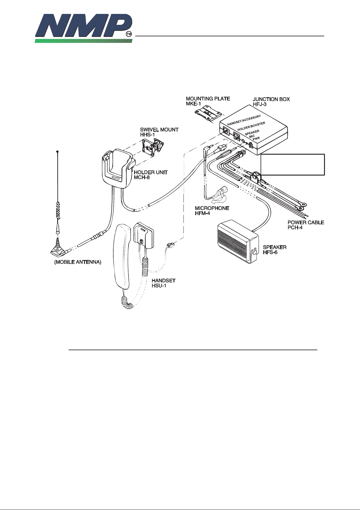
Full Handsfree Car Kit Installation
4–5
Copyright Nokia Mobile Phones
RED = + BATT 12 V
BLACK = – BATT GROUND
BLUE = IGNITION SENSE
YELLOW = RADIO MUTE
Not supplied !
Product List
Item: Remarks: Type:
Mobile base MCH–8
HF junction box HFJ–3
Mounting plate (w/16 screws) MKE–1
Swivel mount (w/6 screws) HHS–1
HF microphone (w/flat mounting plate) HFM–4
HF loudspeaker (w/2 fused conn. & wire ends) PCH–4
Power cable LCP–1
Handset option HSU–1
Modular 8 pin extension cable SCE–4
Page 6

INST ALLATION INSTRUCTIONS
NHE–1/3/4
03/97JR
Technical Documentation
Mounting Plate and Swivel (MKE–1 and HHS–1)
The mounting plate MKE–1 and swivel mount HHS–1 mounting brackets are
interchangeable. Either one can be used to mount both the MCH–8 or the
HFJ–3. The MKE–1 is a fixed position mount and HHS–1 is a swivel mount
which allows for adjustable mounting angles.
Mobile Holder (MBH–6)
The easiest way to attach the phone to the car is to use ”Light Car Kit” installation. The mobile holder MBH–6 is attached the car by using mounting plate
MKE–1 or swivel mount HHS–1.
Compact HF Holder (PHF–1)
Compact HF holder (PHF–1) provides and controls the supply voltage and
charge current for the handportable. In addition, it controls the audio paths to
handsfree equipment, and provides external antenna connection (mini–UHF).
4–6
Copyright Nokia Mobile Phones
Cigarette Lighter Cable (LCP–2)
The cigarette lighter cable LCP–2 connects to the compact HF holder (PHF–1)
via the 5.5 mm d.c. plug. The other connector in the cable (LCP–2) is plugged
to the standard cigarette lighter jack of the vehicle.
Supply voltage may vary between 10.8 and 15.6 volts.
WARNING!
– MAXIMUM SUPPLY VOLTAGE IS 15.6 VOLTS, MINUS (–) IN THE CHASSIS OF THE
VOLTAGE!
– OVERVOLTAGE OR WRONG POLARITY MAY CAUSE SERIOUS DAMAGE TO THE
CAR KIT!
Page 7

INST ALLATION INSTRUCTIONS
NHE–1/3/4
Holder Unit (MCH–8)
The holder unit MCH–8 is used for attaching the phone to the vehicle. It provides connections to external antenna and junction box HFJ–3. Holder unit will
be attached in the vehicle by using mounting plate or swivel mount.
Junction Box (HFJ–3)
Handsfree junction box HFJ–3 provides connections between different functional parts of the car installation, supply feed, handset, holder unit and auxiliary
connections. It is attached to the vehicle with mounting plate MKE–1, or swivel
HHS–1.
Supply feed is coming directly from vehicle battery via power cable PCH–4.
Junction box provides supply feed for handset and handheld phone. It also includes charger for charging the battery of the phone.
Optional handset HSU–1 is connected to the 8 pin modular female connector
HANDSET/ACCESSORY located in the edge of the junction box. If the junction
box is installed far away from the handset or holder unit, extension cable
SCE–4 should be used.
03/97JR
Technical Documentation
4–7
Copyright Nokia Mobile Phones
The cable from holder unit is connected to the other 8 pin female connector
HOLDER next to handset connector.
Handsfree microphone and loudspeaker have male plugs, which are connected
to their female counterparts in the junction box. The diameters are 2.5 and 3.5
mm respectively. Connectors are marked MIC and SPEAKER.
Handsfree Microphone and Speaker (HFM–4 and HFS–6)
The safest and easiest way to have call while driving is use the handsfree option. The system consist of two components, the microphone HFM–4 and loudspeaker HFS–6.
The handsfree microphone can usually be installed on the drivers sunvisor or
A–pillar. The main idea is to get the microphone as close to the drivers mouth
as possible, and to attach the microphone to a surface that is mechanically
quiet. The microphone connects to the HFJ–3 MIC jack.
The loudspeaker should be mounted at least 3 ft./1 m away from the handsfree
mic to avoid acoustic feedback The loudspeaker connects to the HFJ–3
SPEAKER jack.
Page 8

INST ALLATION INSTRUCTIONS
NHE–1/3/4
Power Cable (PCH–4)
The power cable includes supply wires, ignition sense and car radio muting.
The power cables are connected directly to the vehicles battery via fuses, red
wire to the positive pole (+12 V) and black one to the negative pole (GND), unless vehicle has other main voltage than 12 V. The last 1 m part of the cable is
connected by using standard grimp–connectors, which makes power cable
routing from the battery easier. For additional information see section ”Power
Distribution”
The yellow wire is used for car radio muting (XCRM). The line goes down to 0
volts during a call. The maximum sink current is 250 mA, hence the actual muting operation must be done by using an auxiliary relay, or a muting unit provided by the manufacturer, see ”Car Radio Muting”.
The blue ignition sense (IGNS) wire is connected to +12 V voltage controlled by
the car ignition key. The ignition sense can utilize voltages up to 24 V, see section ”Ignition Sense”
Handset (HSU–1)
03/97JR
Technical Documentation
4–8
Copyright Nokia Mobile Phones
An optional handset offers more privacy during the call. The holder is attached
with mounting plate MKE–1 or swivel HHS–1.
Modular 8 Pin Extension Cable (SCE–4)
This cable provides an extension between the HFJ–3 and MCH–4.
SCE–4
Page 9

INST ALLATION INSTRUCTIONS
NHE–1/3/4
03/97JR
Technical Documentation
Copyright Nokia Mobile Phones
Mobile Holder (MBH–6) and Compact HF Holder (PHF–1) together
The holder unit MBH–6 offers firm attachment. It is usually attached to Compact
HF Holder PHF–1 with the Cradle Adapter Kit (MKE–4N), which includes the
cradle adapter, 4 screws and 4 nuts. To attach the MBH–6 to the PHF–1 first
you have to remove the lower cover of PHF–1 by detaching the four crossheaded screws visible underneath the PHF–1 (Figures 1, 2). Insert the four provided nuts into the corresponding slots in the cradle adapter MKE–4N, and
slide the cradle adapter into its place underneath the MBH–6 (Figure 3). Do not
use mounting plate MKE–1 in place of cradle adapter MKE–4N. Mount MBH–6
to its slot in the front part of PHF–1, and finally attach it by using the provided
screws (Figures 4, 5). It is also possible to use the MBH–6 as a separate mobile holder, it is then attached to the vehicle with MKE–1 or HHS–1.
4–9
FIG 1 FIG 2
FIG 3 FIG 4
FIG 5
Page 10

INST ALLATION INSTRUCTIONS
NHE–1/3/4
Antenna
03/97JR
Technical Documentation
Copyright Nokia Mobile Phones
4–10
Note! The car kit is designed to operate with a high quality external
antenna. However, due to many different types of antenna available
an antenna is NOT included as part of this kit. It is the responsibility
of the dealer to advise on the most suitable type for a given
installation.
The most important component of the installation is the antenna. The location
of the antenna as well the quality of the antenna and its installation have a considerable influence to the overall performance of the whole system. Therefore it
is necessary to emphasize some aspects, which too often have caused unnecessary service work.
The best place for the antenna is the rooftop. The overall performance of a
rooftop antenna is clearly superior to any other antenna type or location. The
Antenna shall be mounted in a position such that no part of human body will
normally rest too close to any part of the antenna unless there is a an interventing metallic screen, for example, the metallic roof.
• highest place in the car
• proper ground place
• omnidirectional radiation pattern
• minimum risk for disturbances
• user safety
After drilling the hole for the antenna remember to clean the hole from the drilling swarf, so that surface is even. This is needed in order to ensure proper and
reliable connection between the ground plane and the antenna. After cleaning it
is advised to apply some rust–proofing compound to the hole.
Mount the base of the antenna tightly to its place. Consult the antennas manuals for determing the maximum bending angle before attempting any bending
operation.
To avoid drilling a hole in the vehicle’s bodywork, a glass–mounted antenna can
be chosen and located on the rear window of the vehicle.
Try to route the antenna cable so that possible sources of disturbances are
avoided, as well anti–skid brake systems. The shorter the antenna cable, the
smaller the attenuation, and the better the performance of the antenna. The radio equipment shall be connected to the antenna via a non–radiating cable (eg.
coaxial cable).
Most of the antennas today have adapted the minigrimp connector system
which eliminates the need for special grimping tools and connectors. If however
the purchased antenna has traditional connectors, use only proper connectors
and tools. The mounting bracket uses TNC–female type antenna connector for
reasons of reliability and attenuation.
Page 11
INST ALLATION INSTRUCTIONS
NHE–1/3/4
Power Distribution
The main supply for car kit is obtained from the vehicle battery, the supply voltage may vary between 9 and 16 volts. Both the positive voltage and the
grounding are taken directly from the battery, unless the vehicle has other main
voltage than + 12 V. This minimizes the risk of disturbances from or to the telephone as well as guarantees loss–free power distribution.
The connections to the battery should be carried out with care. Both the negative and positive leads have 4 A fuses, which must always be used. If a fuse
blows, replace it only with the same type and size fuse.
The power cables should be routed so that possible sources of disturbances
are avoided. Also ABS–sensors and like should be avoided as far as possible.
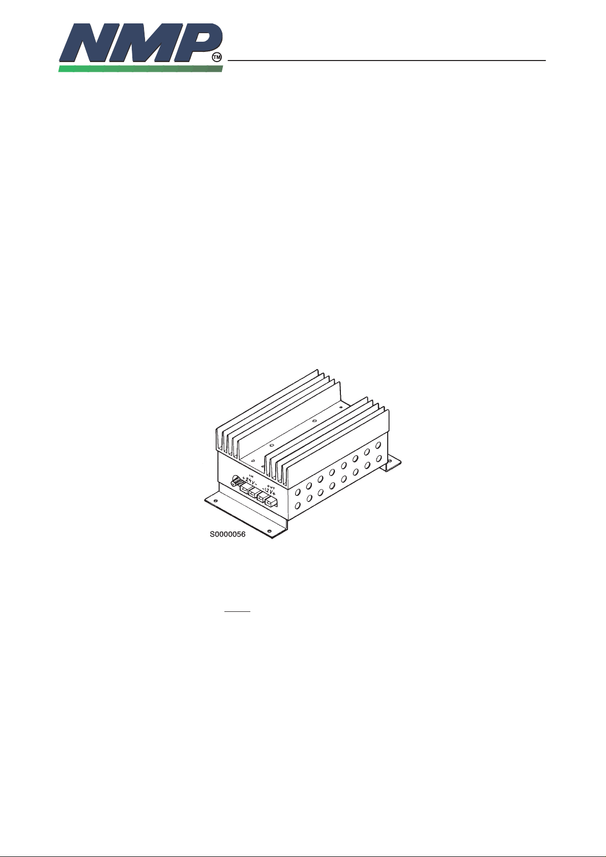
If the vehicle has + 24 V electrical system (trucks, all–terrain vehicles , etc.), an
external voltage reducer must be used. Since the properties of the reducer are
critical, it is recommended to use a reducer supplied by the manufacturer. This
reducer has good protections against transients produced by vehicles electrical
system and it is also capable to maintain stabile output during rapid changes in
load current.
03/97JR
Technical Documentation
4–11
Copyright Nokia Mobile Phones
Some vehicles have a main switch (e.g. gas trucks), which separates the vehicles chassis from the negative lead of the battery. Under no circumstances do
not pass this switch, i.e. the grounding of the reducer must be taken from the
body of the vehicle, NOT
DO NOT INSTALL REDUCER:
To engine compartment
–
– Where there isn’t adequate amount of air for cooling (under the carpet, etc.)
– Where there is risk of moisture (condensated water, etc.)
directly from the battery.
Page 12

INST ALLATION INSTRUCTIONS
NHE–1/3/4
Car Radio Muting (XCRM)
The phone offers a feature that can mute the car radio automatically during a
conversation. This feature is convenient and provides for safer handsfree operation. The car radio muting feature based on grounded line, so it means that
in standby, the yellow wire (XCRM) is not grounded and car radio works normally, but during a call, line is grounded and car radio is muted. The maximum
load that this line can handle is 250 mA. Note that an auxiliary relay or muting
unit must be used when the car radio doesn’t have a mute feature available.
When a relay is used, it is connected in
series with the car radio main supply.
A 200 mA fuse should be used to
protect the XCRM output in event of
a short circuit. Some radios have
separate supplies for amplifiers and
motors, and another for memory
backup purposes. Very often these
radios also have a secret code system,
which activates itself if a break in the
memory supply is detected. Be careful
when installing the relay not to break
the memory supply (usually marked
ACC or +MEM), but to install the relay
in the main supply feed.
03/97JR
Technical Documentation
CAR
RADIO
To XCRM line
(PCH–4/yellow)
Copyright Nokia Mobile Phones
Bosch P/N 0–332–204–150
12 V, 30 A. SPDT
87A
30
87
85
Supply for
car radio
86
Fuse 200 mA
(not supplied)
4–12
12 V d.c.
12 V d.c.
Another possibility is to use a special muting unit (SR59), which mutes the radio
by connecting load resistors to the speaker lines of the car radio. Four loudspeakers can be muted and the maximum permitted power is 20 watts per
channel. The muting unit can also be used as a relay to cut the main supply
feed of the car radio.
Ignition Sense (IGNS)
The ignition sense feature prevents the transceiver from draining the car battery by executing an auto power off 20 seconds after the ignition key has been
turned off.
The blue wire of the power cable is used for the ignition sense feature. The use
of IGNITION SENSE is recommended to prevent accidental draining of the
car’s battery. The wire is connected via a 200 mA fuse to a 12/24 volts potential
that is controlled by the ignition key. Do not connect it directly to the high voltage sections of the ignition circuit.
If the feature is not used, just left the wire unconnected, and protect the end of
the cable with insulating tape.
Page 13

INST ALLATION INSTRUCTIONS
NHE–1/3/4
Positioning
The best guide for positioning the units is your own experience, skills and common sense. However, some aspects requiring special attention will be discussed here.
The positioning of the holder unit is the most important factor when trying to
achieve the most comfortable usage for the user. The location of the holder unit
should be selected so that the visibility of the phone display is good in every
lighting condition, but not so that the drivers attention gets easily distracted
from driving itself. The holder unit should be located so that the driver can easily reach the keypad. Under no circumstances should the holder unit obstruct
the driver from operating car controls (i.e. handbrake, etc.) or observing the
traffic.
If handset is used like a phone & a holder unit, the handset’s place should be
located according same rules as holder unit is located. If using handset, the
location of the phone is not so critical. In this case location of the phone is determined by the connecting cables and the the obtainable of the phone.
03/97JR
Technical Documentation
4–13
Copyright Nokia Mobile Phones
Junction box can also be installed in hidden location, since usually there is no
need to detach cables in normal operation. Remember although that the housing doesn’t like moisture or mechanical pressure.
Handsfree microphone can usually be installed in the sunvisor of the driver, or
in the A–pillar. The main idea is to get the microphone quite close to the drivers
mouth, and also to attach the microphone in surface that doesn’t carry the mechanical vibrations of the car body, since these will increase the background
noise when using handsfree.
The loudspeaker isn’t so sensitive for vibrations, thus it can be located more
freely. The main idea is to optimize two requirements: The driver should hear
the signal from the loudspeaker without any special efforts, but the the attenuation between loudspeaker and microphone should be as high as possible, i.e.
they must ”look” in other directions in order to minimize the acoustic feedback.
The system cable routing isn’t usually critical; however it should not be routed
next to electronic ignition systems or ABS braking systems wires or boxes to
prevent interference to important automotive electrical components. Take also
care not to run the cable so that it gets under any mechanical stress e.g. under
seats or against sharp edges of car chassis. The holder unit should be always
connected to the antenna via a non–radiating cable (e.g. coax).
The antenna shall be mounted in a position such that no part of the human
body will normally rest close to any part of the antenna unless there is an intervening metallic screen, for example, the metallic roof.
All installations should take into account any special requirements of the customer. However, should the customer require an installation that is illegal on unsafe these facts must be pointed on the customer and a policy of non–compliance adopted.
Page 14

INST ALLATION INSTRUCTIONS
NHE–1/3/4
03/97JR
Technical Documentation
4–14
Copyright Nokia Mobile Phones
This page intentionally left blank.
 Loading...