


nokia 201 x
Service Manual for L1 and L2
z
z
z
z
z
Nokia Asha 210
RM-924, RM-928 (DS)
RM-925, RM-926, RM-929 (SS)
Key features
2.0 Mpix camera with innovative features
2.4" LCD display with 65k colors
QWERTY keyboard for fast and seamless messaging
Dual SIM functionality (RM-924, RM-928)
MicroSD card support up to 32 GB
Version 1.0
Check the repair
policy before
performing any
mechanical repair
on Service Level
1&2!
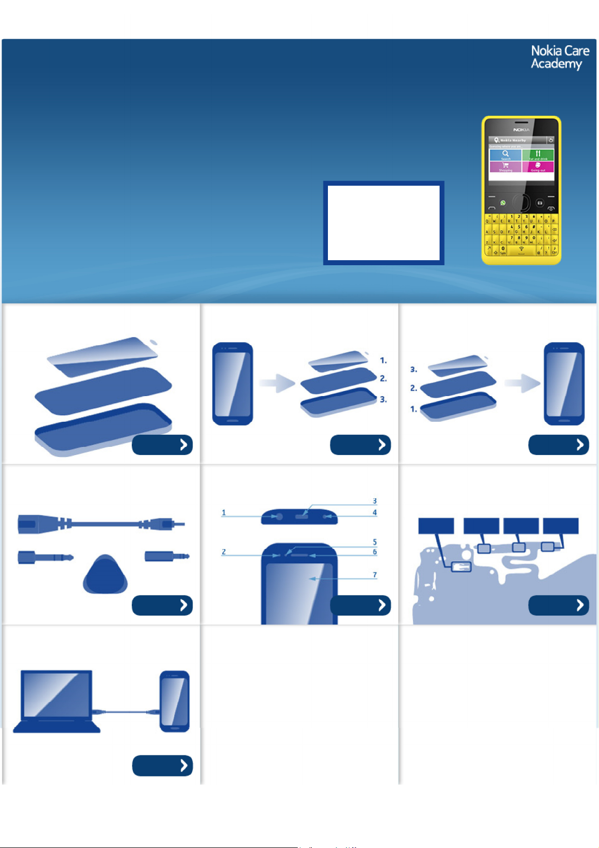
Exploded view Disassembly steps Assembly hints
More More More
Service devices Product controls and interfaces Solder components
Service concept
More More More
More
©2013 Nokia | Nokia Internal Use only | All Rights Reserved.
Service Manual Level 1 and 2
Nokia Asha 210
RM-924, RM-925, RM-926, RM-928, RM-929
Version 1.0
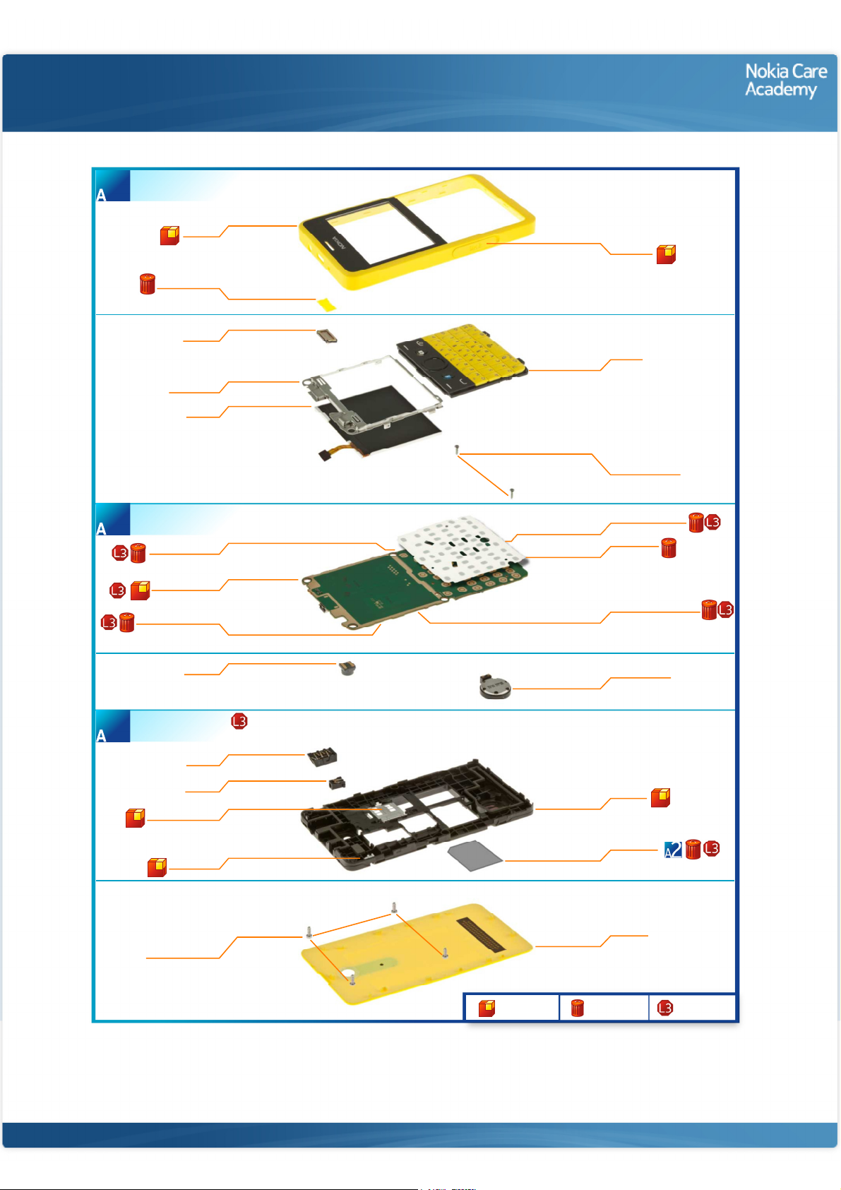
A-COVER ASSEMBLY
(I0001 - I0003)
1
A-COVER
I0001
EARPIECE MESH
I0003
EARPIECE
I0004
UI ASSEMBLY
I0007
DISPLAY
I0008
Exploded view
SIM DOOR
I0002
KEYMAT
I0005
SCREW TORX+
SIZE 4 RF 1.4 x 4.5
I0006
LIGHT SWAP PACKAGE
(I0009 - I0015)
2
BB SHIELDING LID
LIGHT SWAP PWB
WLAN SHIELDING LID
D-COVER ASSEMBLY
(I0017 - I0021 )
3
SIM LID ASSEMBLY
I0011
I0010
I0013
CAMERA
I0016
AV JACK
I0020
DC JACK
I0021
I0017
BT ANTENNA
I0018
FEM SHIELDING LID
I0012
DOMESHEET
I0009
BT_FEM SHIELDING LID
I0014
3 IN 1 SPEAKER
I0023
D-COVER
I0019
TYPE LABEL
I0015
SCREW TORX+
SIZE 6 RF 1.6 x 4.5
I0022
Only available
as assembly
©2013 Nokia | Nokia Internal Use only | All Rights Reserved.
B-COVER
I0024
Not reuseable
after removal
Repair/swap
only in level 3
Service Manual Level 1 and 2
Nokia Asha 210
RM- 924, RM- 925, RM- 926, RM- 928, RM-929
Version 1.0
Disassembly steps
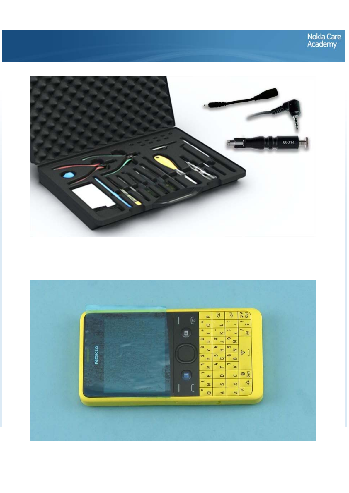
1) For disassembling you need the Nokia Standard toolkit version 2. You will also need a DC plug, an AV
plug and the camera removal tool SS-276. Note that the disassembly instructions are made with the dual
SIM variant (RM-924).
2) Protect the A-COVER with protective film.
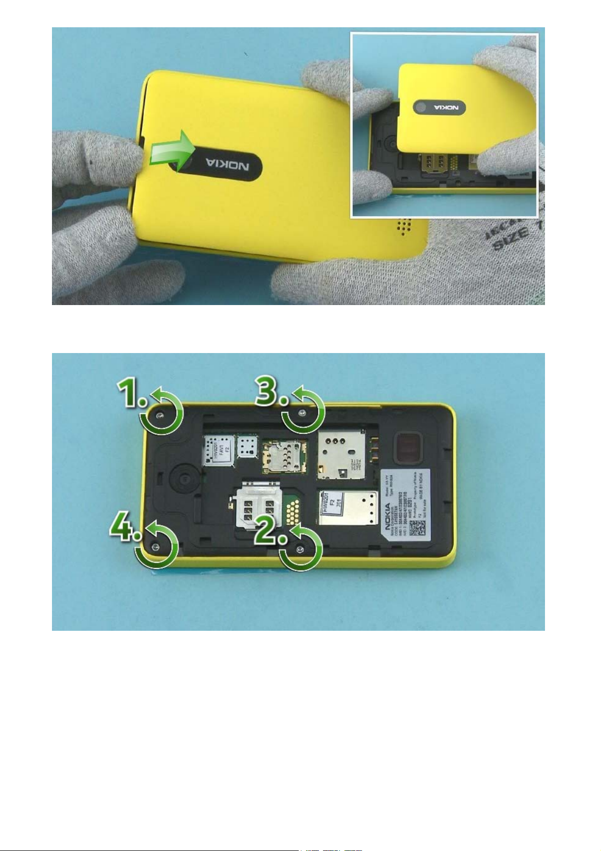
3) Use the finger groove to release the B-COVER
4) Unscrew the four Torx+ size 6 screws in the order shown.
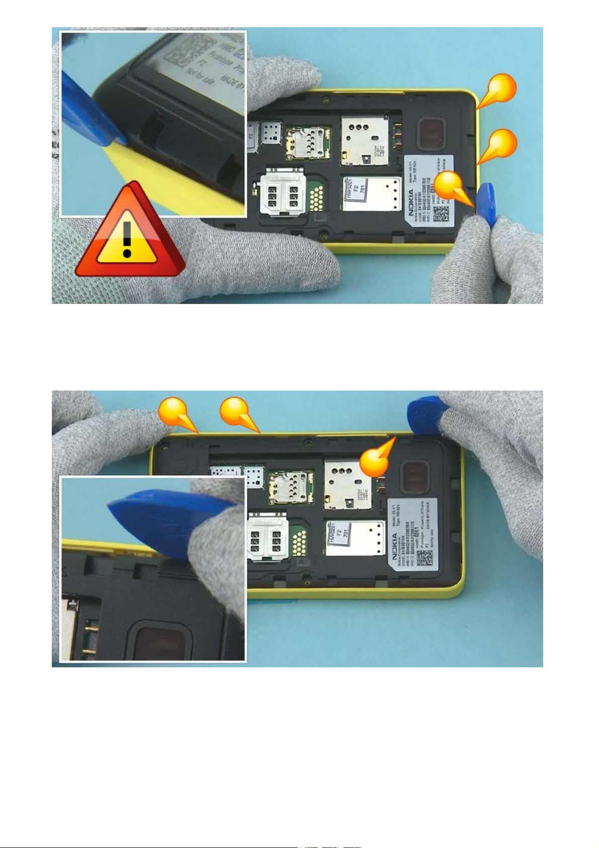
5) Start releasing the A-COVER from the bottom end of the device. Insert the SRT-6 between the ACOVER and D-COVER and release the three clips holding the A-COVER.
NOTE: SRT-6 must be inserted vertically to avoid damages in A-COVER.
6) Then release the shown clips on the SIM DOOR side. Pay attention not to damage the A-COVER.
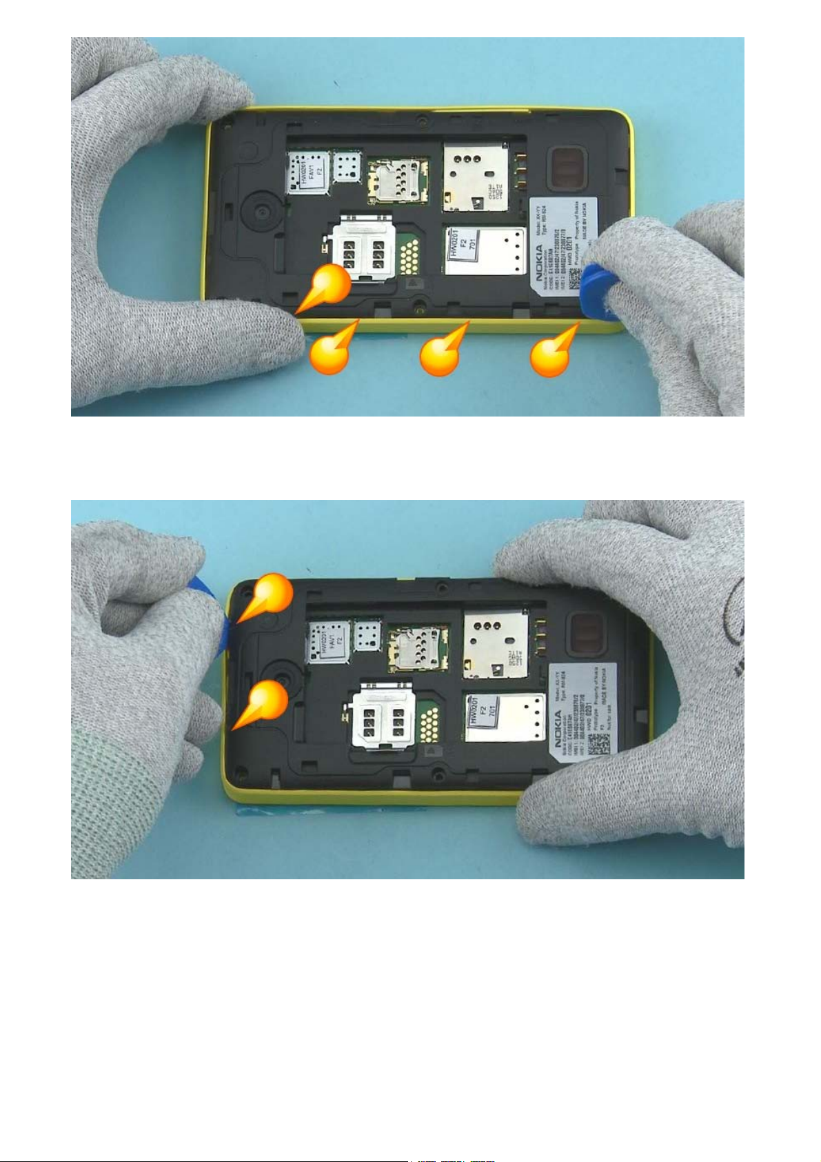
7) Release also the clips on the other side of the device with the SRT-6. Pay attention not to damage the
A-COVER.
8) Use the SRT-6 to release the two clips on the top end of the device. Pay attention not to damage the
A-COVER.
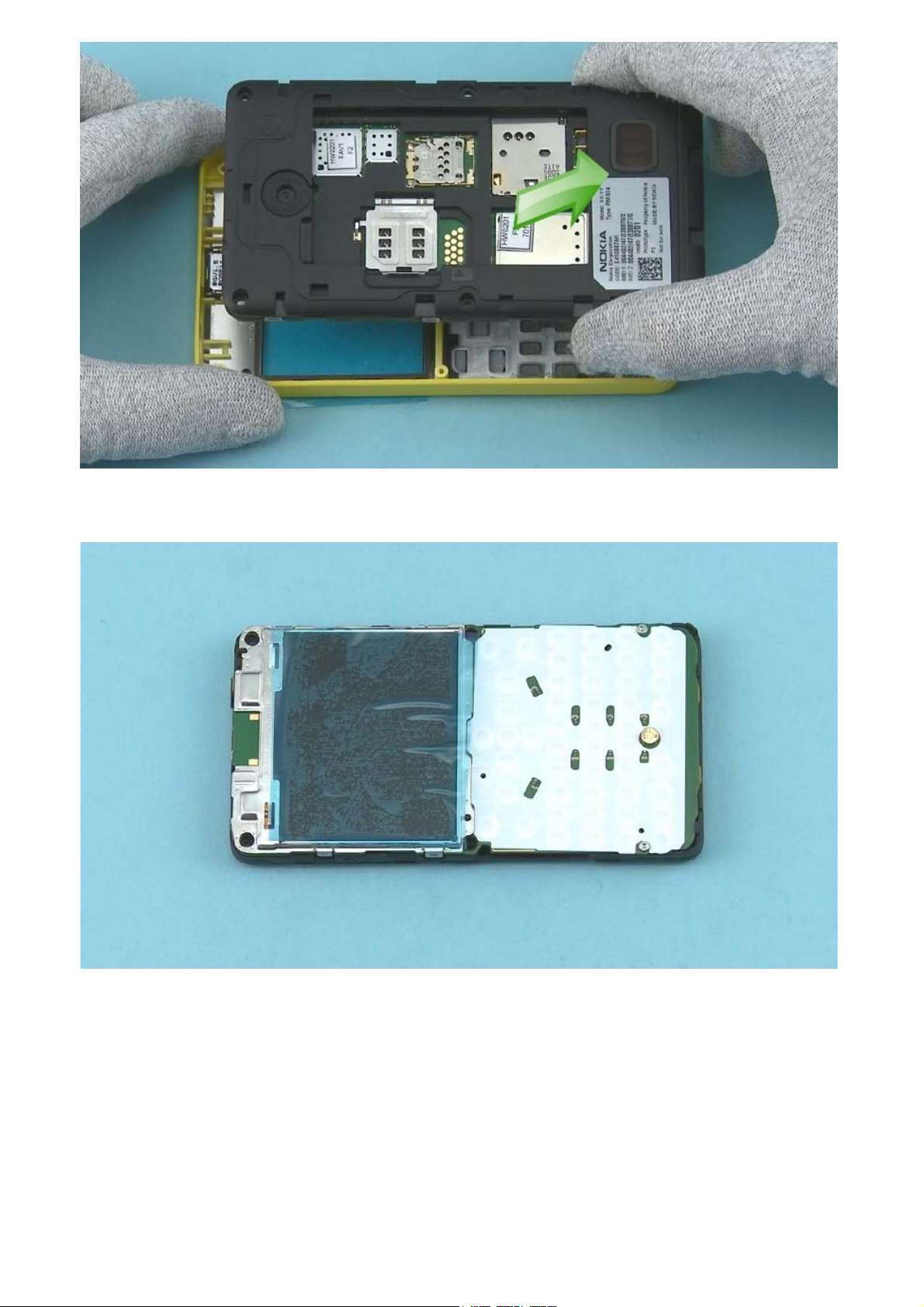
9) The A-COVER and the D-COVER with the ENGINE BOARD can now be separated.
10) Protect the DISPLAY with protective film.
11) Protect also the other side of the A-COVER window.
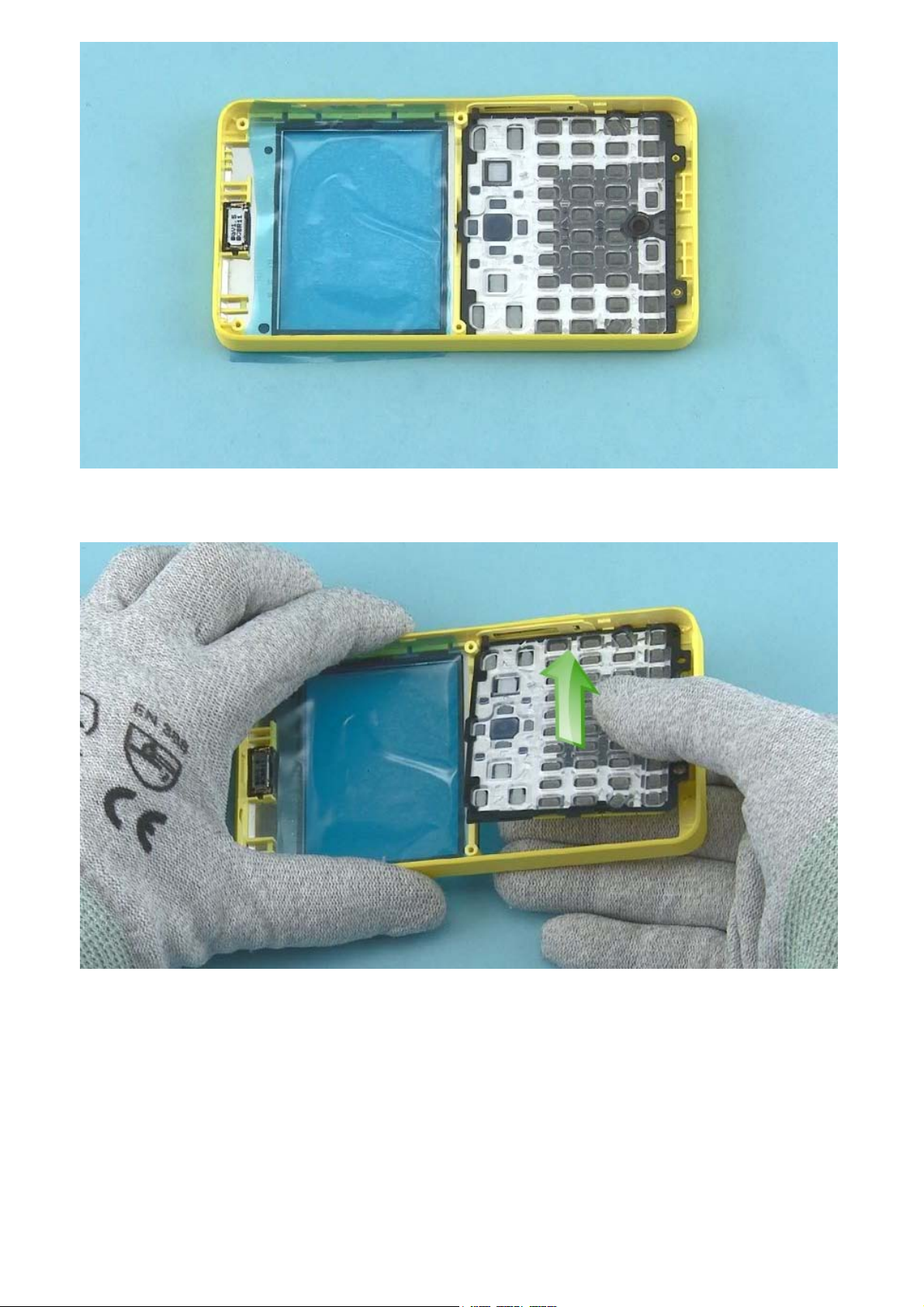
12) Detach the KEYMAT by pushing it with fingers.