


C TRANSMISSION/TRANSAXLE
A
B
SECTION
CONTENTS
FS5W71C
PREPARATION ..................................... ...................... 3
Special Service Tools ............................................... 3
Commercial Service Tools ........................................ 5
NOISE, VIBRATION, AND HARSHNESS (NVH)
TROUBLESHOOTING .......................... ...................... 6
NVH Troubleshooting Chart ..................................... 6
DESCRIPTION ......................... ................................... 7
CROSS-SECTIONAL VIEW ..................................... 7
ON-VEHICLE SERVICE ............................................. 9
Replacing Rear Oil Seal ........................................... 9
REMOVAL ............................................................. 9
INSTALLATION ..................................................... 9
Position Switch Check .............................................. 9
TRANSMISSION ASSEMBLY .................................. 10
Removal and Installation ........................................ 10
REMOVAL ........................................................... 10
INSTALLATION ....................................................11
Overhaul ......................... .................... .................... 12
CASE COMPONENTS ........................................ 12
GEAR COMPONENTS ....................................... 14
SHIFT CONTROL COMPONENTS ...... ....... ....... 16
CASE COMPONENTS ............................... ....... ....... 18
Disassembly ................... ........................................ 18
Assembly ........................ .................... .................... 19
SHIFT CONTROL COMPONENTS .......................... 22
Disassembly ................... ........................................ 22
Inspection ................. .............................................. 22
Assembly ........................ .................... .................... 23
GEAR COMPONENTS ............................................. 24
Disassembly ................... ........................................ 24
Inspection ................. .............................................. 26
GEARS AND SHAFTS ........................................ 26
SYNCHRONIZERS .................. ........................... 27
BEARINGS ......................... ............. ............. ....... 27
Assembly ........................ .................... .................... 27
SERVICE DATA AND SPECIFICATIONS (SDS) ...... 35
General Specifications ........................................... 35
Gear End Play ........................................................ 35
Clearance Between Baulk Ring and Gear ............. 36
MANUAL TRANSMISSION
2ND & 3RD BAULK RING ................................... 36
Available Snap Rings .............................................36
MAIN DRIVE GEAR BALL BEARING SNAP
RING ................................................................... 36
MAINSHAFT FRONT SNAP RING ......................36
COUNTER DRIVE GEAR SNAP RING ...............36
OD MAINSHAFT BEARING SNAP RING ...........37
Available Shims ......................................................37
COUNTERSHAFT FRONT BEARI NG SHIM ...... 37
FS5R30A
PREPARATION ................................. ........................38
Special Service Tools .............................................38
Commercial Service Tool ........................................ 40
NOISE, VIBRATION, AND HARSHNESS (NVH)
TROUBLESHOOTING ...................... ........................41
NVH Troubleshooting Chart ...................................41
DESCRIPTION ............... ........................................... 42
Description ................... ...... ....... ...... ........................42
CROSS-SECTIONAL VIEW — 2WD MODEL .....42
CROSS-SECTIONAL VIEW — 4WD MODEL .....44
ON-VEHICLE SERVICE ............................................46
Replacing Rear Oil Seal — 2WD Model .................46
REMOVAL ...........................................................46
INSTALLATION ...................................................46
Position Switch Check ....... ....... ...... ....... ...... ....... ....46
TRANSMISSION ASSEMBLY ..................................48
Removal and Installation ........................................ 48
REMOVAL ...........................................................48
INSTALLATION ...................................................50
Overhaul ............... ..................................................51
CASE COMPONENTS ........................................ 51
GEAR COMPONENTS .......................................53
SHIFT CONTROL COMPONENTS (2/4WD
MODELS) ............................................................ 57
CASE COMPONENTS .............................................. 59
Disassembly ........................................................... 59
Assembly ..................... ........................................... 61
MT
D
E
F
G
H
I
J
K
L
M
MT-1

SHIFT CONTROL COMPONENTS ........................... 63
Disassembly ...........................................................63
Inspection ............................................................... 63
Assembly ................................................................63
GEAR COMPONENTS ..............................................65
Disassembly ...........................................................65
Inspection ............................................................... 69
GEARS AND SHAFTS ........................................69
SYNCHRONIZERS .............................................69
BEARINGS ......................... .................................70
Assembly ................................................................70
SERVICE DATA AND SPECIFICATIONS (SDS) ......81
General Specifications ............................................81
Gear End Play ............................. ....... ...... ....... .......81
Clearance Between Single Baulk Ring and Gear ...81
DOUBLE BAULK RING .......................................82
Distance Between Rear Surface of Reverse Cone
and Reverse Baulk Ring .........................................82
Available Snap Ring ................................................82
MAIN DRIVE GEAR SNAP RING ........................82
MAINSHAFT FRONT BEARING SNAP RING .....82
COUNTER GEAR REAR SNAP RING ................83
Available C-ring .......................................................83
MAINSHAFT C-RING ..........................................83
Available Shim and Washer ....................................83
T ABLE FOR SELECTING PROPER COUNTER
GEAR FRONT BEARING SHIM ..........................83
REVERSE IDLER REAR THRUST WASHER .....83
MT-2
PREPARATION
[FS5W71C]
PREPARATION PFP:00002
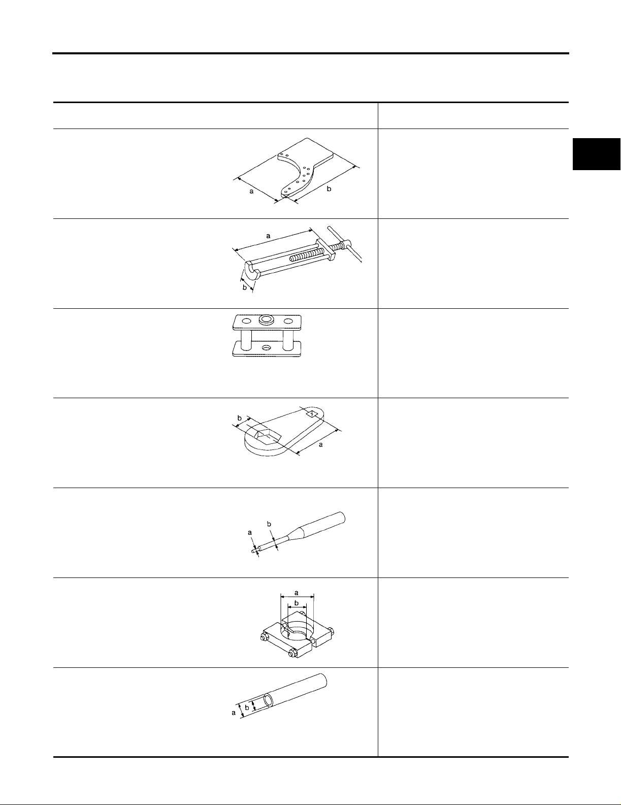
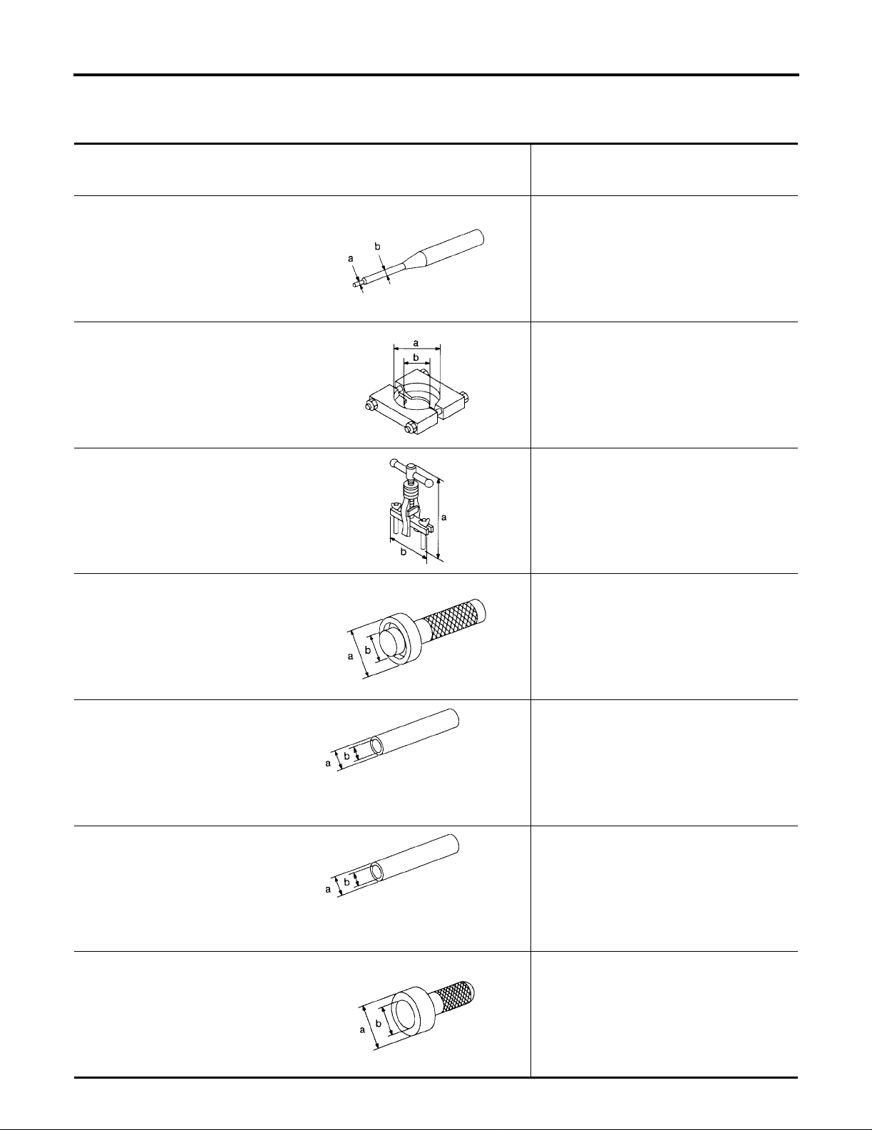
Special Service Tools
The actual shapes of Kent-Moore tools may differ from those of spec ial ser vi ce tool s illust rat ed here.
Tool number (Kent-Moore No.) Tool
name
ST23810001
( — )
Adapter setting plate
NT407
KV32101330
(See J34286)
Puller
NT408
KV31100401
( — )
Transmission press stand
Description
Fixing adapter plate with gear assembl y
a: 166 mm (6.54 in)
b: 270 mm (10.63 in)
Removing overdrive mainshaf t beari ng
a: 447 mm (17.60 in)
b: 100 mm (3.94 in)
Pressing counter gear, mainshaft, count er
drive gear and main drive gear
ECS006I2
A
B
MT
D
E
F
G
ST22520000
(J26348)
Wrench
ST23540000
(J25689-A)
Pin punch
ST30031000
(J22912-01)
Puller
NT068
NT409
NT442
Tightening mainshaft lock nut
a: 100 mm (3.94 in)
b: 41 mm (1.61 in)
Removing and installing fork rod reta inin g pin
a: 2.3 mm (0.091 in) dia.
b: 4 mm (0.16 in) dia.
Removing and installing 1st gear bushi ng
Removing main drive gear ball bearing
a: 90 mm (3.54 in) dia.
b: 50 mm (1.97 in) dia.
H
I
J
K
L
M
ST23860000
( — )
Drift
NT411
Installing counter drive gear
a: 38 mm (1.50 in) dia.
b: 33 mm (1.30 in) dia.
NT065
MT-3
PREPARATION
[FS5W71C]
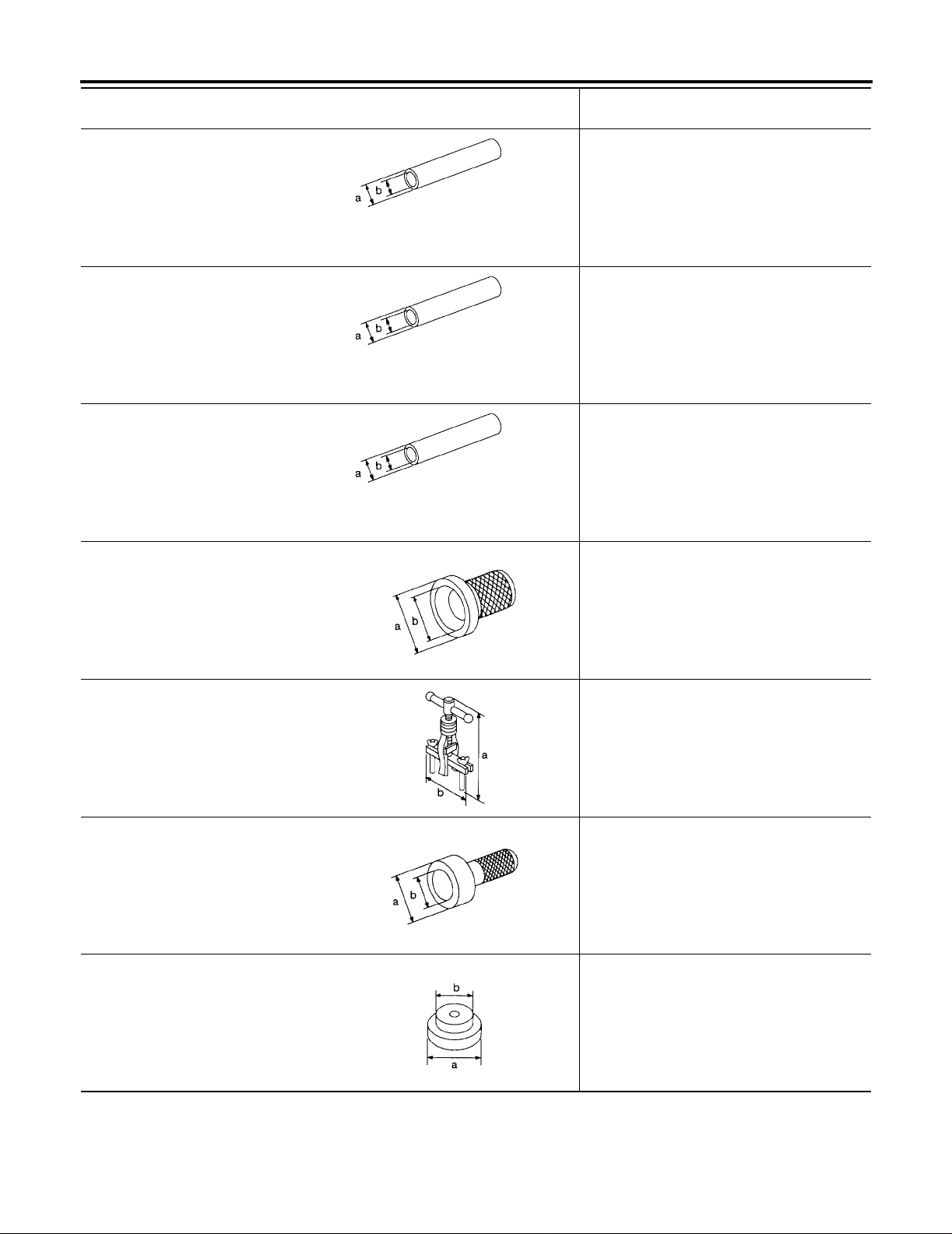
Tool number (Kent-Moore No.) Tool
name
ST22360002
(J25679-01)
Drift
ST22350000
(J25678-01)
Drift
ST23800000
(J25691-01)
Drift
ST33400001
(J26082)
Drift
Description
Installing counter gear front and rear end
bearings
a: 29 mm (1.14 in) dia.
b: 23 mm (0.91 in) dia.
NT065
Installing OD gear bushing
a: 34 mm (1.34 in) dia.
b: 28 mm (1.10 in) dia.
NT065
Installing front cover oil seal
a: 44 mm (1.73 in) dia.
b: 31 mm (1.22 in) dia.
NT065
Installing rear oil seal
a: 60 mm (2.36 in) dia.
b: 47 mm (1.85 in) dia.
ST33290001
(J34286)
Puller
ST30720000
(J25405)
Drift
ST30613000
(J25742-3)
Drift
NT086
Removing rear oil seal
a: 250 mm (9.84 in)
b: 160 mm (6.30 in)
NT414
Installing mainshaft ball bearing
a: 77 mm (3.03 in) dia.
b: 55.5 mm (2.185 in) dia.
NT115
Installing main drive gear ball bearing
a: 71.5 mm (2.815 in) dia.
b: 47.5 mm (1.870 in) dia.
NT073
MT-4
PREPARATION
[FS5W71C]
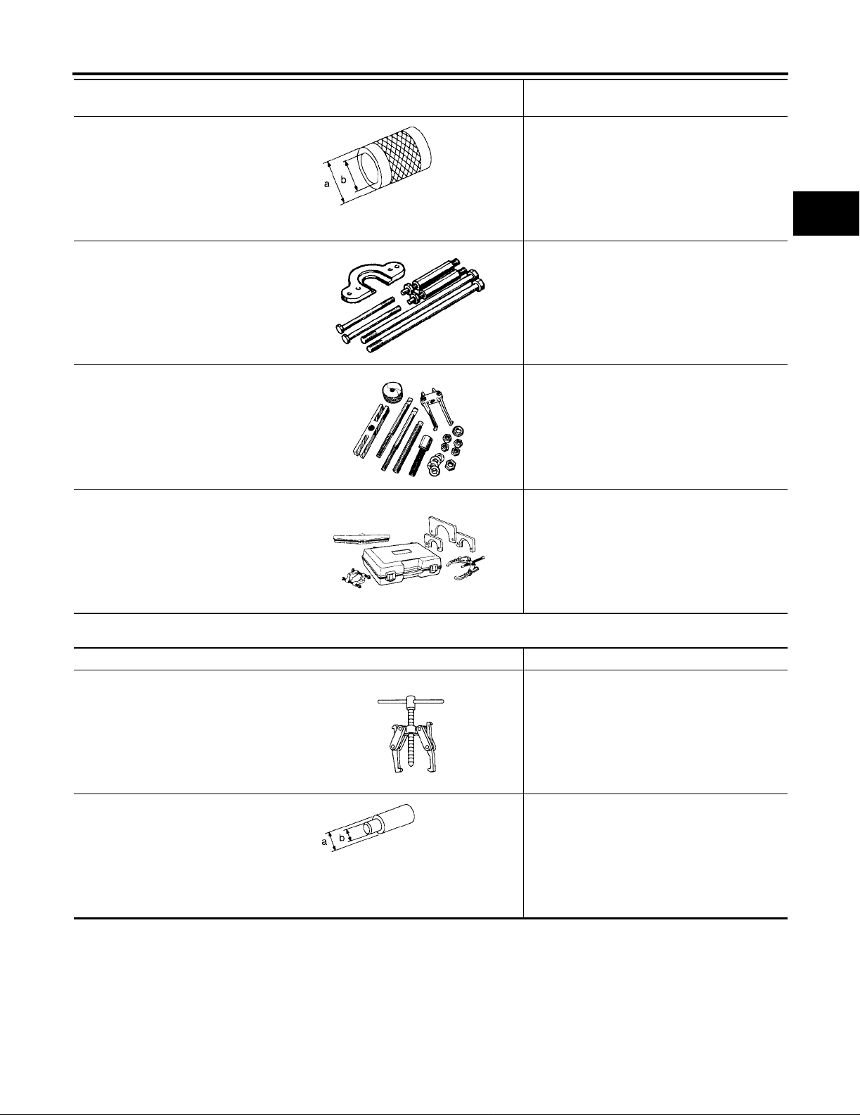
Tool number (Kent-Moore No.) Tool
name
ST33200000
(J26082)
Drift
(J-26349-A)
Bearing Remover and Installer Set
(J-34286)
Rear Race Puller
(J-39856)
Gear and Bearing Removal Kit
NT091
WMT065
WMT066
Description
Installing counter rear bearing and count er
gear assembly
a: 60 mm (2.36 in) dia.
b: 44.5 mm (1.752 in) dia.
Removing and installing mainsh af t bea ring
(Use with J-25726-B)
Removing races
Removing gears and bearings
A
B
MT
D
E
F
G
H
WMT067
Commercial Service Tools
Tool name Description
Puller Removing counter bearings, counter drive
and OD gears
NT077
Drift Installing countershaft rear end bearing
a: 40 mm (1.57 in) dia.
b: 30 mm (1.18 in) dia.
NT074
I
J
ECS006I3
K
L
M
MT-5
NOISE, VIBRATION, AND HARSHNESS (NVH) TROUBLESHOOTING
[FS5W71C]
NOISE, VIBRATION, AND HARSHNESS (NVH) TROUBLESHOOTING
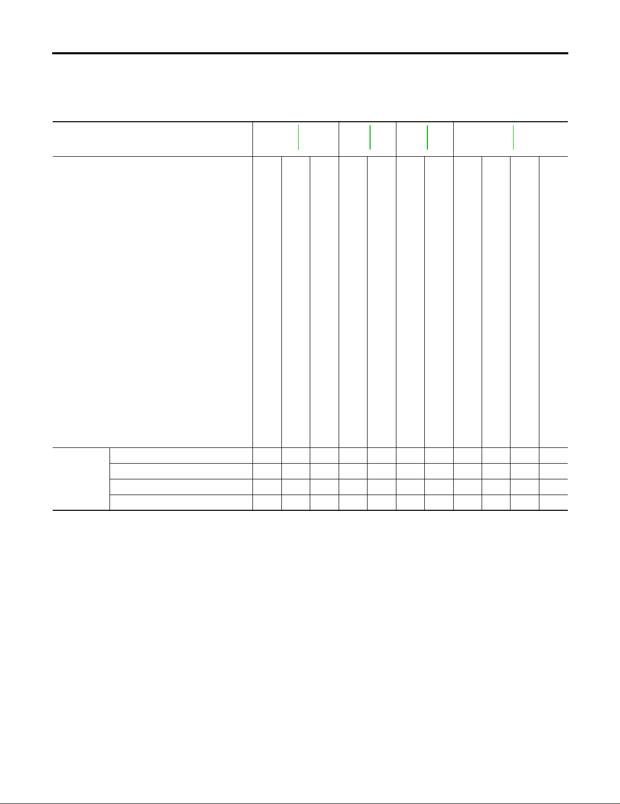
NVH Troubleshooting Chart
PFP:00003
ECS006I4
Use the chart below to help you find the cause of the symptom. The numbers indicate the order of the inspection. If necessary, repair or replace these part s.
Reference page
MA-35
SUSPECTED PARTS
(Possible cause)
MT-18
MT-22
MT-24
Symptom
OIL (Oil level is low .)
OIL (Wrong oil.)
OIL (Oil level is high.)
GASKET (Damaged)
OIL SEAL (Worn or damaged)
CHECK PLUG RETURN SPRING AND CHECK BALL (Worn or damaged)
SHIFT FORK (Worn)
GEAR (Worn or damaged)
BEARING (Worn or damaged)
BAULK RING (Worn or damaged)
Noise 1 2 3 3
Oil leakage 3 1 2 2
Hard to shift or will not shift 1 1 2 2
Jumps out of gear 1 2 2
INSERT SPRING (Damaged)
MT-6
DESCRIPTION
[FS5W71C]
DESCRIPTION PFP:00000
CROSS-SECTIONAL VIEW
ECS006I5
A
B
MT
D
E
F
G
H
K
M
I
J
L
MT-7
WCIA0175E

DESCRIPTION
[FS5W71C]
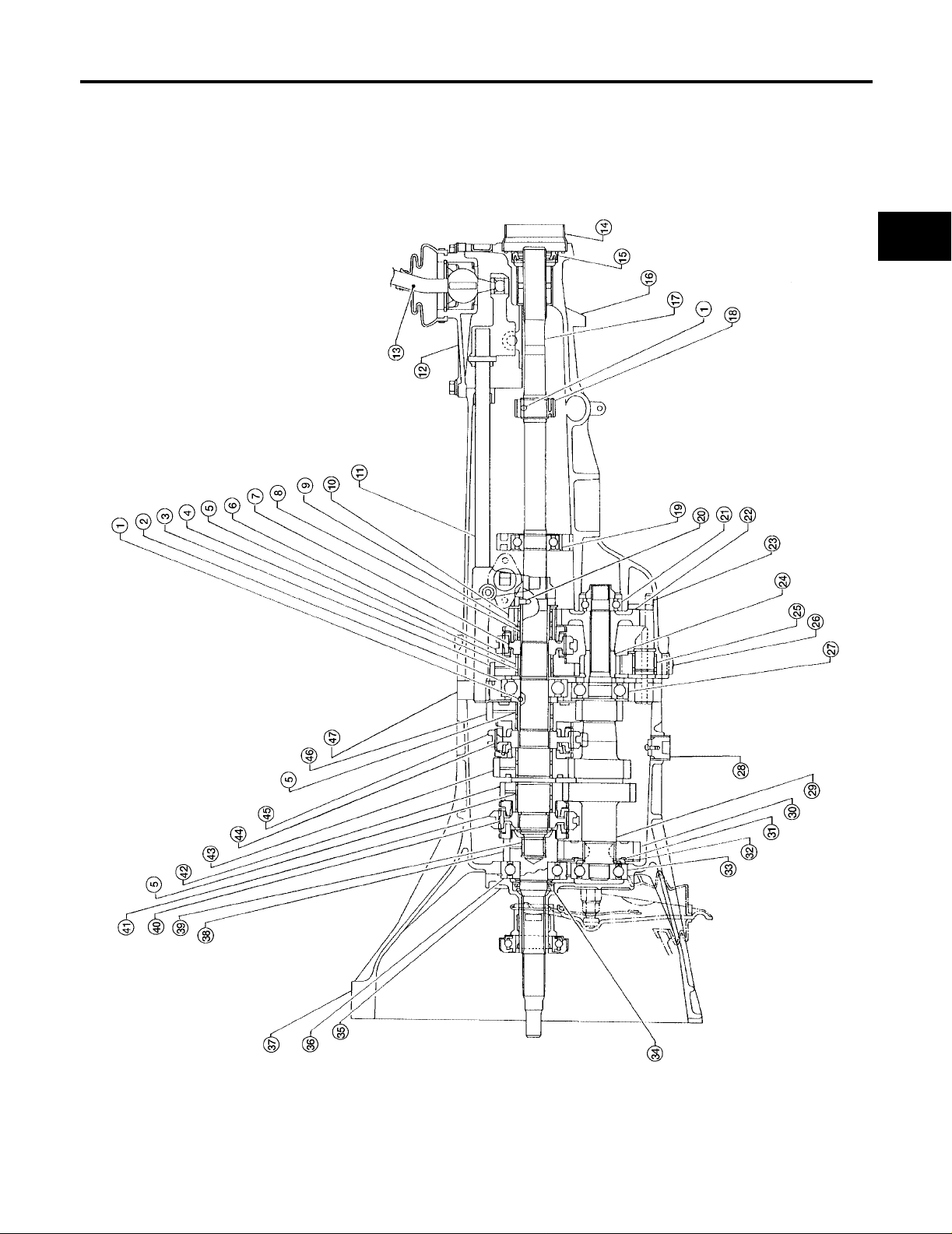
1. Steel ball 2. Mainshaft front bearing 3. Reverse main gear
4. Bushing 5. Needle bearing 6. OD & Reverse coupling sleeve
7. OD & Reverse synchronizer hub 8. OD gear bushing 9. Needle bearing
10. OD main gear 11. Striking rod 12. Control housing
13. Shift lever 14. Dust cover 15. Oil seal
16. Rear extension 17. Mainshaft 18. Speedometer drive gear
19. OD mainshaft bearing 20. Steel roller 21. Counter gear rear end bearing
22. OD counter gear 23. Reverse idler shaft 24. Reverse counter gear
25. Reverse idler gear bushing 26. Reverse idler gear 27. Counter gear rear bearing
28. Drain plug 29. Counter gear 30. Counter drive gear
31. Sub gear bracket 32. Sub gear 33. counter gear front bearing
34. Oil seal 35. Front cover 36. Main drive gear ball bearing
37. Transmission case 38. Main drive gear 39. Pilot bearing
40. 3rd & 4th synchronizer hub 41. 3rd & 4th coupling sleeve 42. 3rd main gear
43. 2nd main gear 44. 1st & 2nd synchronizer hub 45. 1st & 2nd coupling sleeve
46. 1st ma in gear 47. Adapter plate
MT-8
ON-VEHICLE SERVICE
[FS5W71C]
ON-VEHICLE SERVICE PFP:00000
Replacing Rear Oil Seal
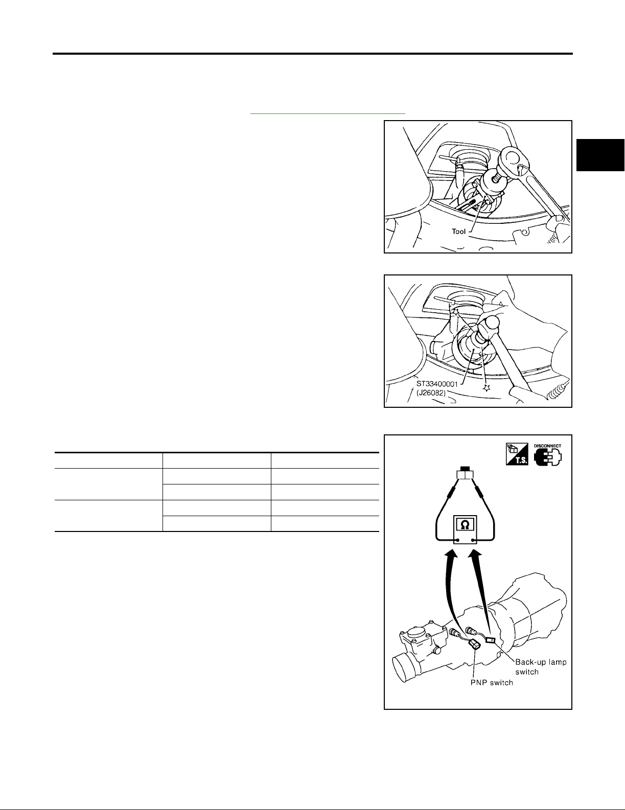
REMOVAL
1. Remove the propeller shaft. Refer to PR-8, "Removal an d Installation" .
2. Remove rear oil seal using Tool.
● Always replace with a new seal once it has been
removed.
Tool number : ST33290001 (J34286)
INSTALLATION
1. Install new rear oil seal using Tool until it stops.
● Apply multi-purpose grease to seal lip of oil seal before
installing.
Tool number : ST33400001 (J26082)
ECS006I6
WCIA0176E
A
B
MT
D
E
F
G
2. Installation is in the reverse order of removal.
Position Switch Check
● Check continuity.
Switch Gear position Continuity
Back-up lamp switch
Park/neutral position
(PNP) switch
Reverse Yes
Except reverse No
Neutral Yes
Except neutral No
SMT480CA
ECS006I7
H
I
J
K
L
M
MT-9
SMT981D
TRANSMISSION ASSEMBLY
[FS5W71C]
TRANSMISSION ASSEMBLY
Removal and Installation
REMOVAL
PFP:32010
ECS006I8
WMT030
CAUTION:
Before separating the transmission from the engine, remove the crankshaft position sensor (OBD)
from the transmission. Be careful not to damage sensor edge or ring gear teeth.
MT-10
TRANSMISSION ASSEMBLY
[FS5W71C]
NOTE:
To prevent oil s pills, drain transmission oil before remo ving transmission or insert plug into rear oil
seal after removing propeller shaft.
● Be careful not to damage spline, sleeve yoke, and rear oil seal when removing propeller shaft.
1. Remove battery negative terminal.
2. Remove the crankshaft position sensor (OBD) from transmission upper side.
3. Remove the clutch operating cylinder fr om transmission. Refer to CL-9, "
4. Disconnect the vehicle speed sensor, back-up switch, and park/neutral position (PNP) switch harness
connectors.
5. Remove the starter motor. Refer to SC-23, "
6. Disconnect the exhaust hanger. Refer to EX-3, "
7. Remove the propeller shaft. Refer to PR-8, "
Removal and Ins tallation" .
Removal and Installation" .
Removal and Installation" .
8. Remove the shift lever.
9. Support the engine by placing a jack under the oil pan.
● Do not plac e jack under oil pan drain plug.
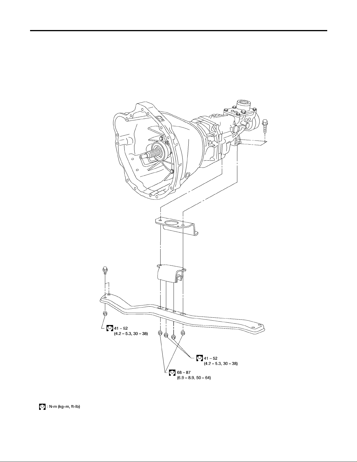
10. Remove the transmission crossmember.
11. Separate the transmission from the engine.
WARNING:
Support manual transmission while removing it.
OPERATING CYLINDER" .
A
B
MT
D
E
F
G
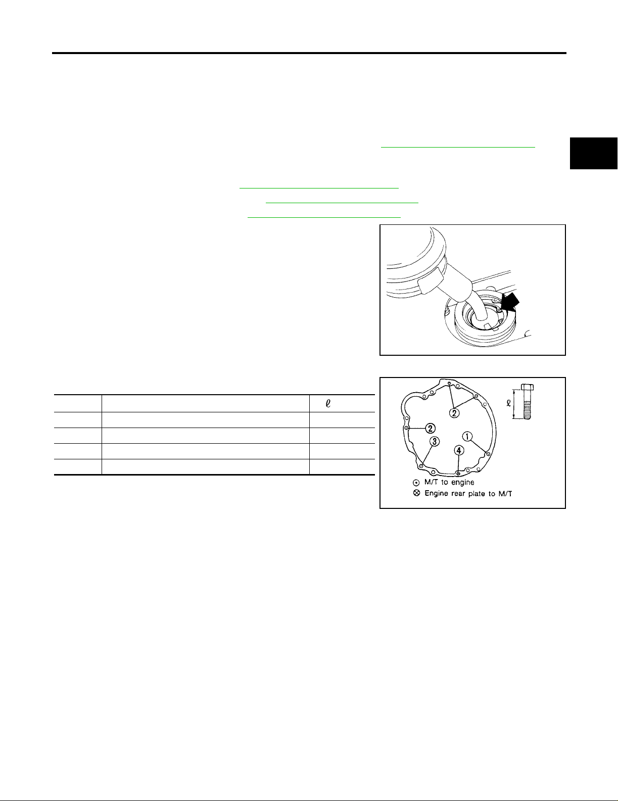
INSTALLATION
1. Tighten transmission bolts.
Bolt No. Tightening torque N·m (kg-m, ft-lb)
1 40 - 49 (4.0 - 5.0, 29 - 36) 65 (2.56)
2 40 - 49 (4.0 - 5.0, 29 - 36) 58 (2.28)
3* 16 - 21 (1.6 - 2.2, 12 - 15) 25 (0.98)
4 16 - 21 (1.6 - 2.2, 12 - 15) 16 (0.63)
*: With nut
2. Installation is in the reverse order of removal.
mm (in)
SMT099A
AMT190
H
I
J
K
L
M
MT-11
TRANSMISSION ASSEMBLY
[FS5W71C]
Overhaul
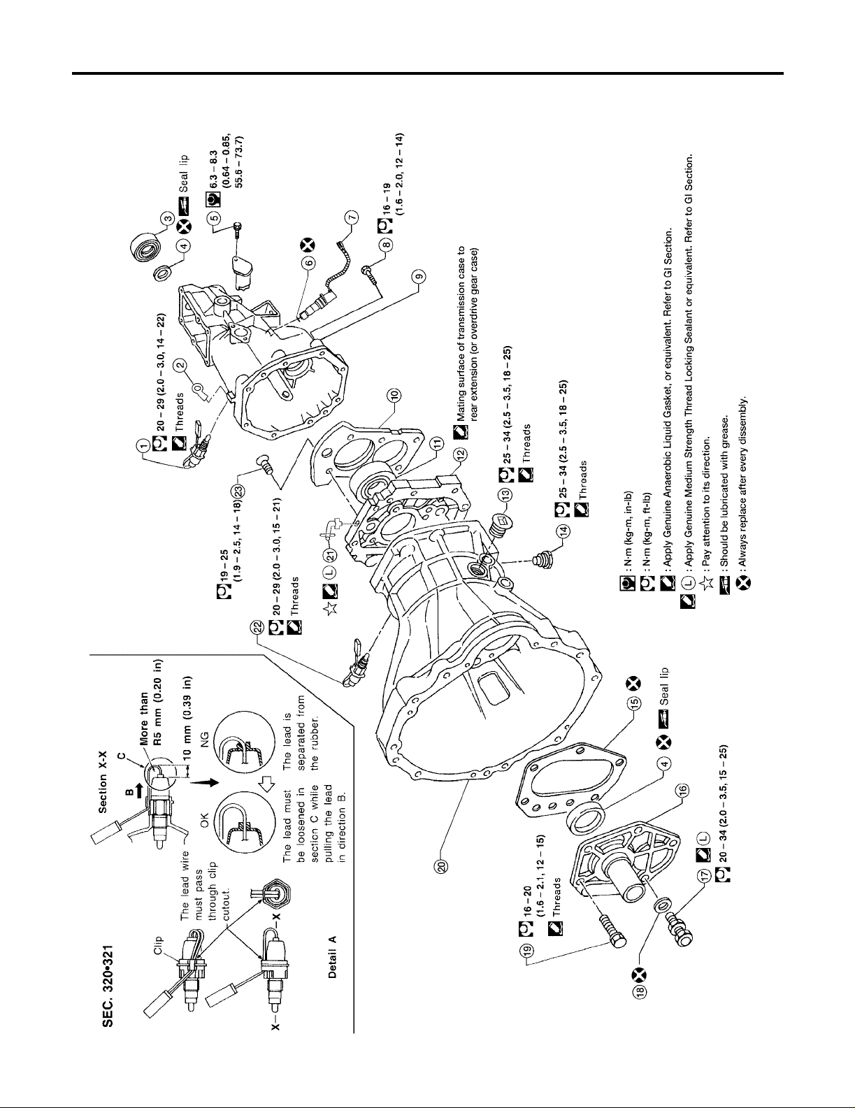
CASE COMPONENTS
ECS006I9
MT-12
WCIA0177E

TRANSMISSION ASSEMBLY
[FS5W71C]
1. Park/neutral position (PNP) switch 2. Clip 3. Dust cover
4. Oil Seal 5. Reverse check sleeve bolt 6. O-ring
7. Vehicle speed sensor 8. Rear extension bolts 9. Rear extension
10. Bearing retainer 11. Bearing 12. Adapter plate
13. Filler plug 14. Drain plug 15. Gasket
16. Front cover 17. Ball pin 18. Washer
19. Front cover bolt 20. Transmission case 21. Air breather
22. Back-up lamp switch
A
B
MT
D
E
F
G
H
K
M
I
J
L
MT-13
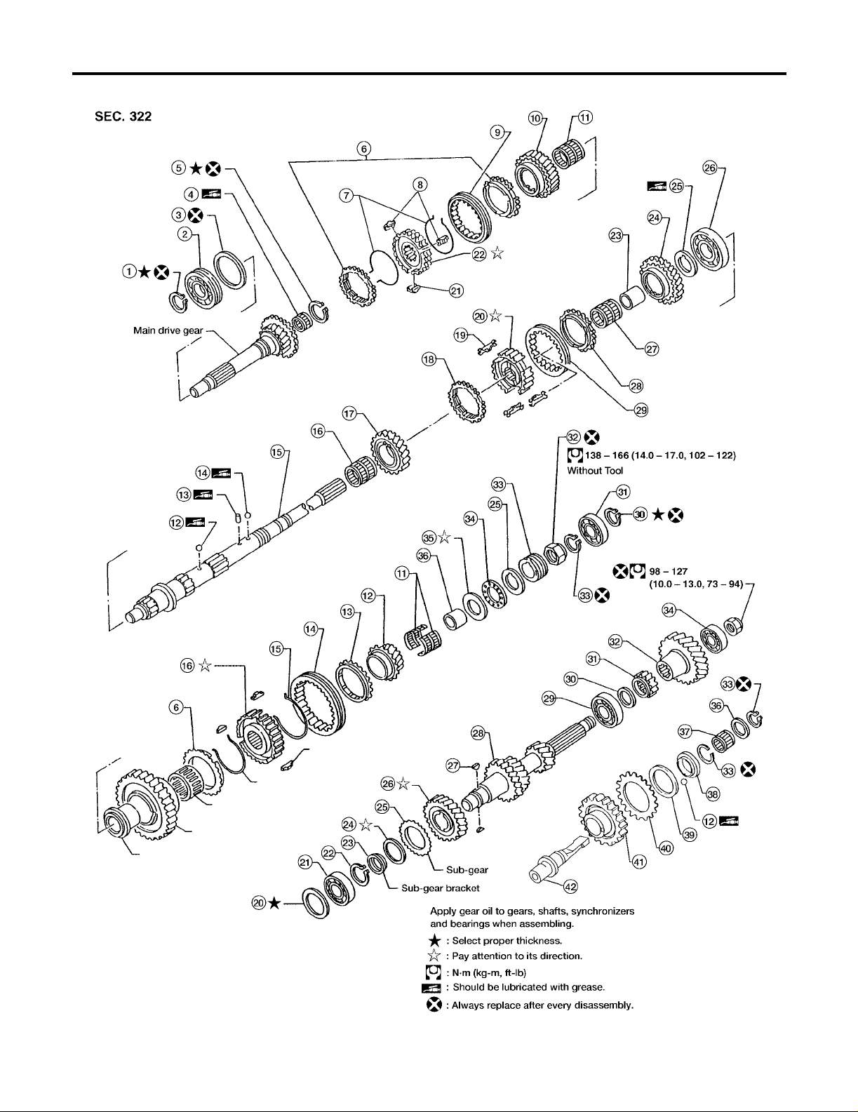
GEAR COMPONENTS
TRANSMISSION ASSEMBLY
[FS5W71C]
MT-14
WCIA0178E

TRANSMISSION ASSEMBLY
[FS5W71C]
1. Main drive gear ball bearing snap ring 2. Main drive gear ball bearing 3. Snap ring
4. Pilot bearing 5. Mainshaft front snap ring 6. Baulk ring
7. Spread spring 8. Shifting insert 9. 3rd and 4th coupling sleeve
10. 3rd main gear 11. Needle bearing 12. Steel ball
13. Steel roller 14. Steel ball 15. Mainshaft
16. 2nd main gear needle bearing 17. 2nd main gear 18. 2nd baulk ring
19. Insert spring 20. 1st and 2nd synchronizer hub 21. Shifting insert
22. 3rd and 4th synchronizer hub 23. 1st gear bushing 24. 1s t main gear
25. 1st gear thrust washer 26. Mainshaft ball bearing 27. N eedle bearing
28. Baulk ring 29. 1st and 2nd coupling sleeve 30. Overdrive mainshaf t be aring snap ring
31. O verdrive mainshaft bearing 32. Mainshaft lock nut 33. Speedometer drive gear
34. C ounter gear rear end bearing 35. Counter gear lock nut 36. Reverse idler thrust wa sher
37. Reverse idler gear bearing 38. Sub-gear bracket 39. Sub-gear spring
40. Sub-gear 41. Reverse idler gear 42. Reverse idler shaf t
A
B
MT
D
E
F
G
H
K
M
I
J
L
MT-15
TRANSMISSION ASSEMBLY
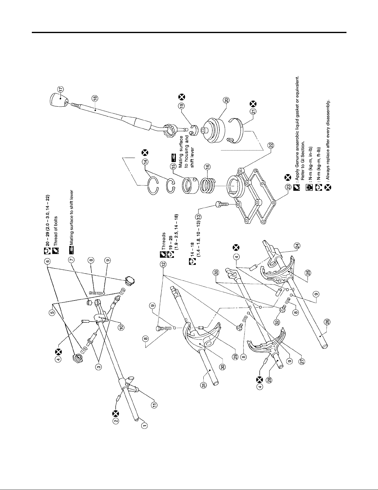
SHIFT CONTROL COMPONENTS
CAUTION:
To avoid damage when replacing shift knob, remove shift lever with knob, as assembled.
[FS5W71C]
1. Striking rod 2. Striking lever retaining pin 3. Select check plunger
4. Retainer pin 5. Return spring 6. Select check plug
7. Bushing 8. Check spring 9. Check ball
10. Striking arm 11. Striking lever 12. Check ball plug
MT-16
WCIA0179E

TRANSMISSION ASSEMBLY
13. Control housing bolt 14. Snap ring 15. Socket
16. Spring 17. Shi f t kno b 18. S hift lev er
19. Upper boot retainer 20. Boot 21. Lower boot retainer
22. Control housing 23. G asket 24. OD and reverse bracket
25. OD and reverse shift fork 26. OD and re verse fork rod 27. 3rd and 4th shift fork
28. 3rd and 4th fork rod 29. I nt erlock plunger 30. 1st and 2nd shift fork
31. 1st and 2nd fork rod 32. Reverse check plug 33. Interlock ball
[FS5W71C]
A
B
MT
D
E
F
G
H
K
M
I
J
L
MT-17
CASE COMPONENTS
[FS5W71C]
CASE COMPONENTS
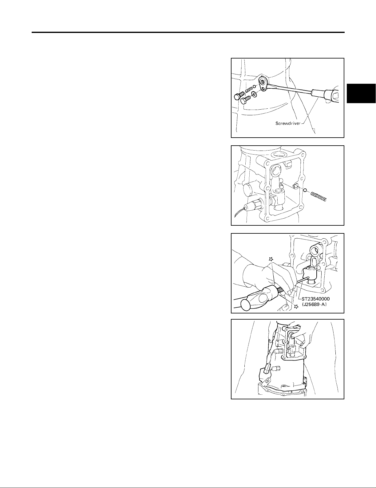
Disassembly
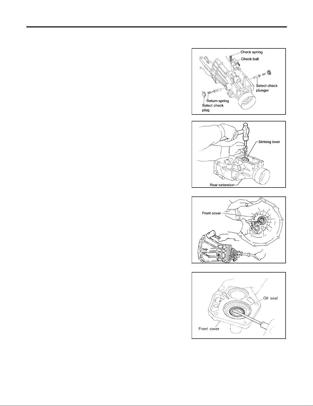
1. Remove rear extension.
a. Remove control housing, check spring, check ball, select check
plugs, return springs and select check plungers. Also remove
reverse check plug, check spring and check ba ll.
● Be careful not to lose check balls.
b. Drive out striking lever retaining pin.
c. Remove striking lever from striking rod.
d. Remove rear extension by lightly tapping on it.
PFP:32100
ECS006IA
WCIA0180E
2. Remove front cover, gasket, counter gear front bearing shim
and main drive gear ball bearing snap ring.
3. Separate transmission case from adapter plate by lightly tapping
on it.
4. Remove oil seal from front cover using a screwdriver.
● Be careful not to damage mating surface of front cover.
AMT132
AMT131
MT-18
SMT166D
CASE COMPONENTS
[FS5W71C]
Assembly
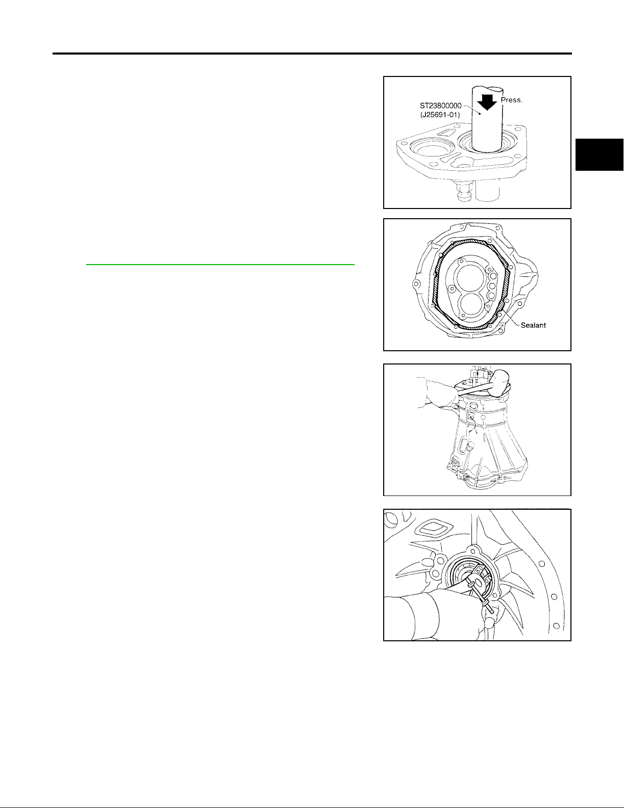
1. Install front cover oil seal using Tool.
● Apply multi-purpose grease to seal lip.
Tool number : ST23800000 (J25691-01)
2. Apply sealant to mating surface of transmission case as shown
in the figure.
● Use Genuine Anae rob ic Li quid Gasket , or eq uiva lent. Refer to
MA-12, "
3. Install adapter plate into transmission case by lightly tapping it
using a soft hammer.
RECOMMENDED FLUIDS AND LUBRICANTS" .
ECS006IB
SMT036
SMT061C
A
B
MT
D
E
F
G
H
4. Install main drive gear ball bearing snap ring.
I
J
K
SMT013
L
M
SMT672A
MT-19
CASE COMPONENTS
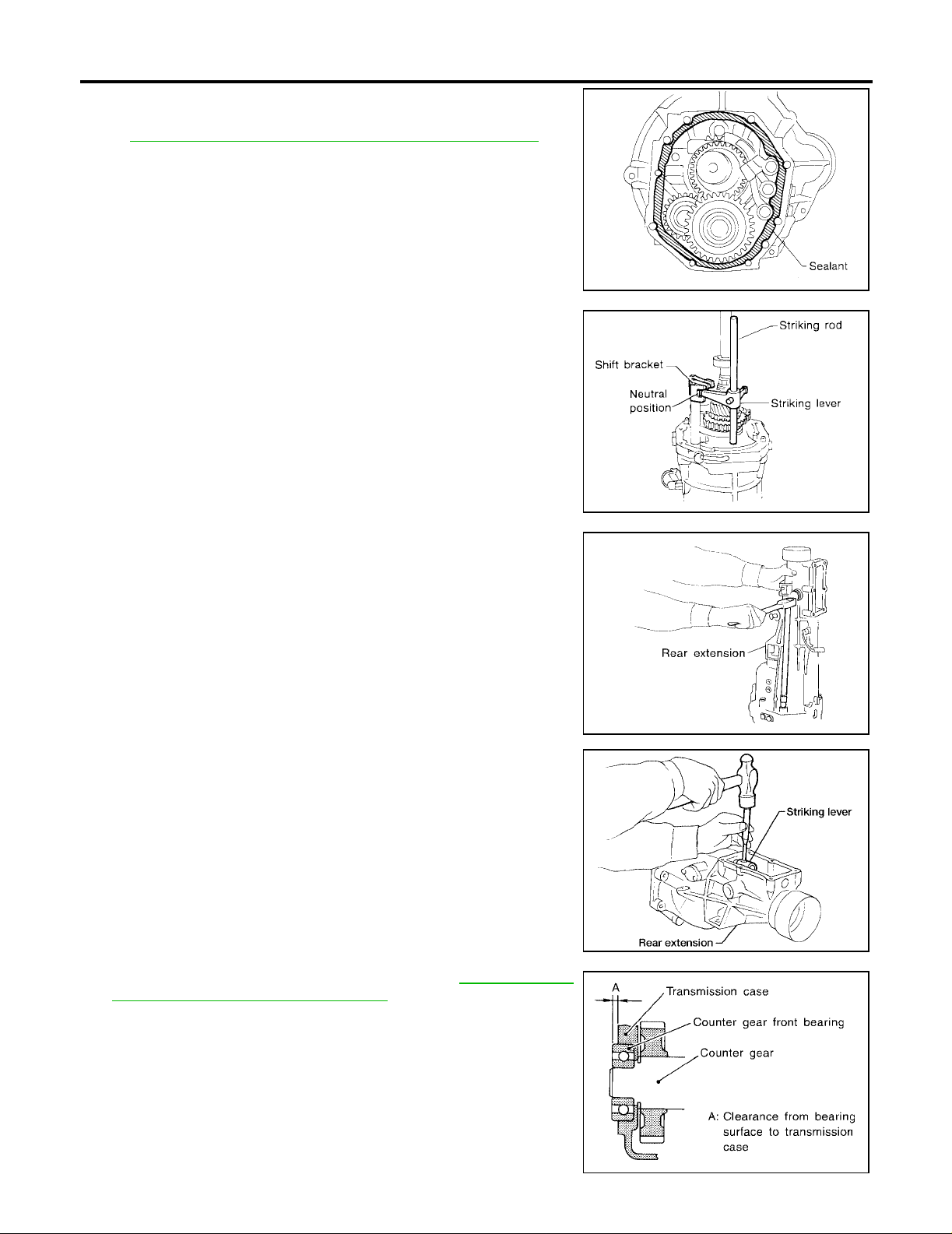
5. Apply sealant to mating surface of adapter plate as shown.
● Use Genuine Anaerobic Liquid Gasket, or equivalent. Refer to
MA-12, "
6. Place shif t forks in neutral position.
7. Install striking leve r and stri ki ng rod on to ad ap te r pla t e an d al ig n
striking lever with shift brackets.
RECOMMENDED FLUIDS AND LUBRICANTS" .
[FS5W71C]
SMT062C
8. Install rear extension.
● Tighten rear extension bolts equally in a crisscross pattern.
Rear extension bolts : 16 - 19 N·m (1.6 - 2.0 kg-m,
12 - 14 ft-lb)
9. Install striking lever retaining pin.
SMT801B
SMT180D
AMT132
10. Select counter gear front bearing shim. Refer to MT-37, "
TERSHAFT FRONT BEARING SHIM" .
Allowable clear ance (A)
: 0 - 0.16 mm (0 - 0.0063 in)
from bearing su rface to
transmission case
11. Install new gasket and front cover.
MT-20
COUN-
SMT205D
CASE COMPONENTS
[FS5W71C]
12. Apply sealant to front cove r bolts. Tighten front cover bolts.
● Use Genuine Anaerobic Liquid Gasket, or equivalent. Refer to MA-12, "RECOMMENDED FLUIDS
AND LUBRICANTS" .
A
Front cover bolts : 16 - 20 N·m (1.6 - 2.1 kg-m, 12 - 15 ft-lb)
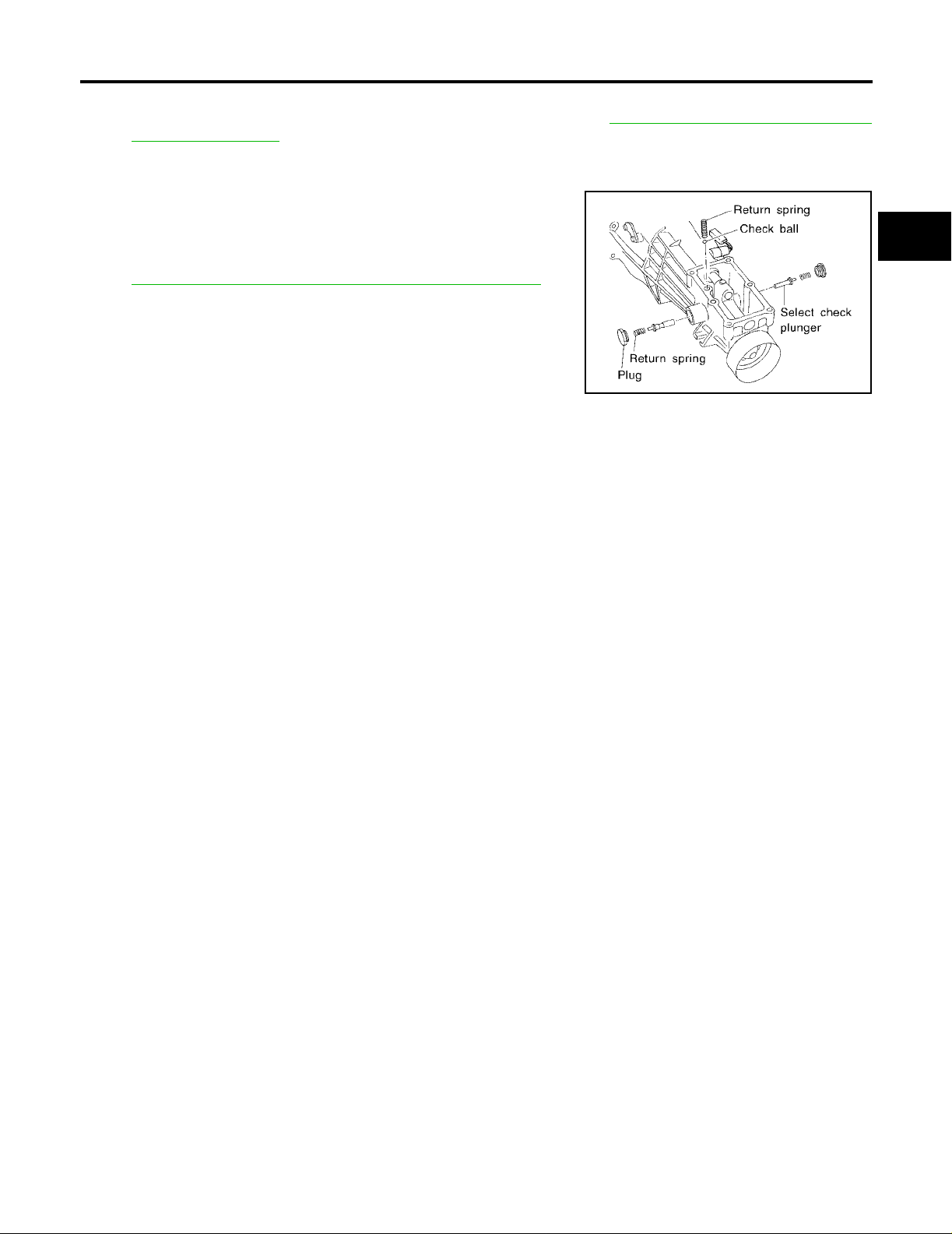
13. Install check ball, check spring, select check plungers and return
springs.
14. Apply sealant to select ch ec k plu gs . Tighten se le ct ch ec k pl ugs.
● Use Genuine Anae rob ic Li quid Gasket , or eq uiva lent. Refer to
MA-12, "
Select check
plugs
RECOMMENDED FLUIDS AND LUBRICANTS" .
: 20 - 29 N·m (2.0 - 3.0 kg-m,
14 - 22 ft-lb)
15. In s tall control housing and new gasket.
Control housing
bolts
: 14 - 18 N·m (1.4 - 1.8 kg-m,
10 - 13 ft-lb)
B
MT
D
E
SMT161D
F
G
H
I
K
M
J
L
MT-21
SHIFT CONTROL COMPONENTS
[FS5W71C]
SHIFT CONTROL COMPONENTS
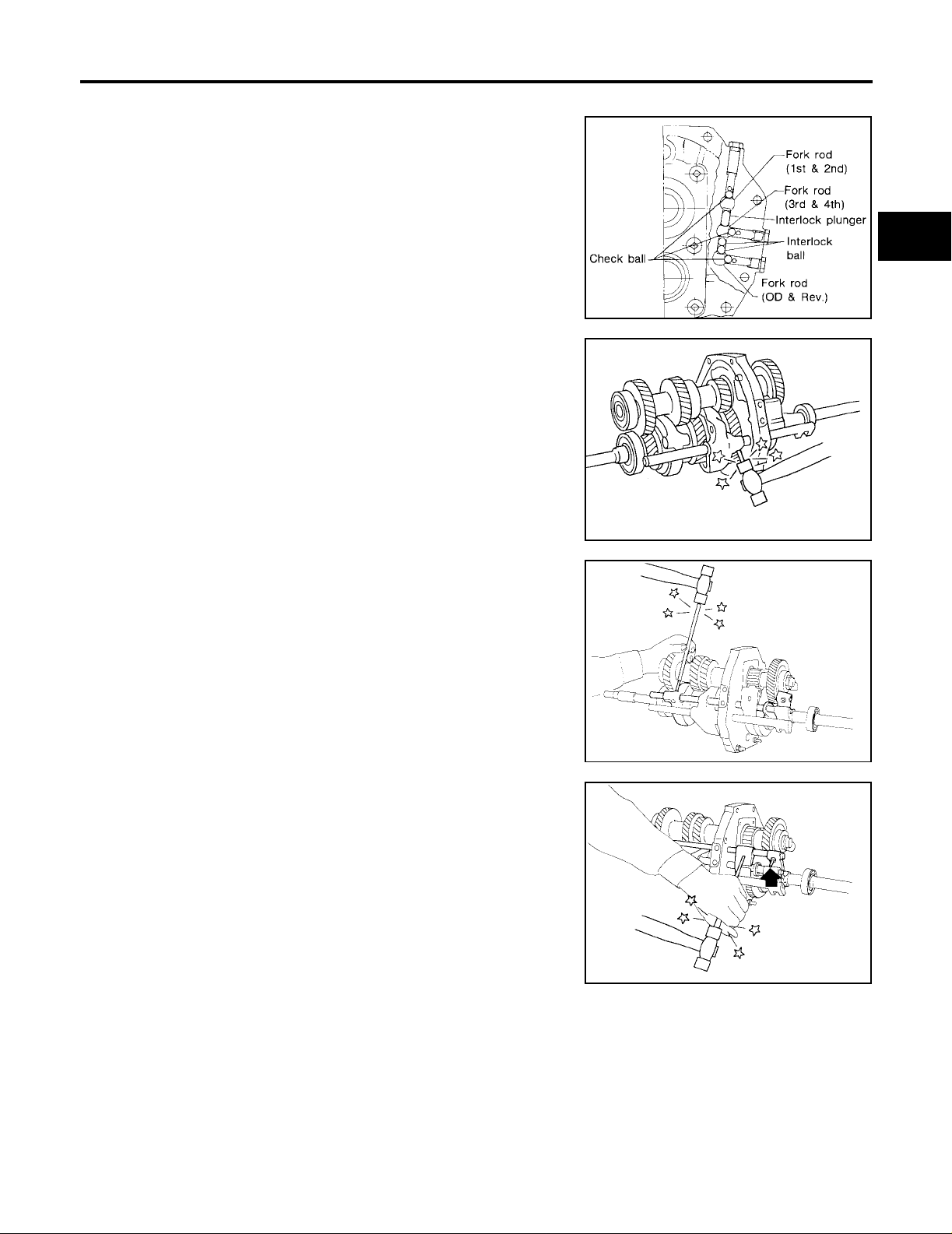
Disassembly
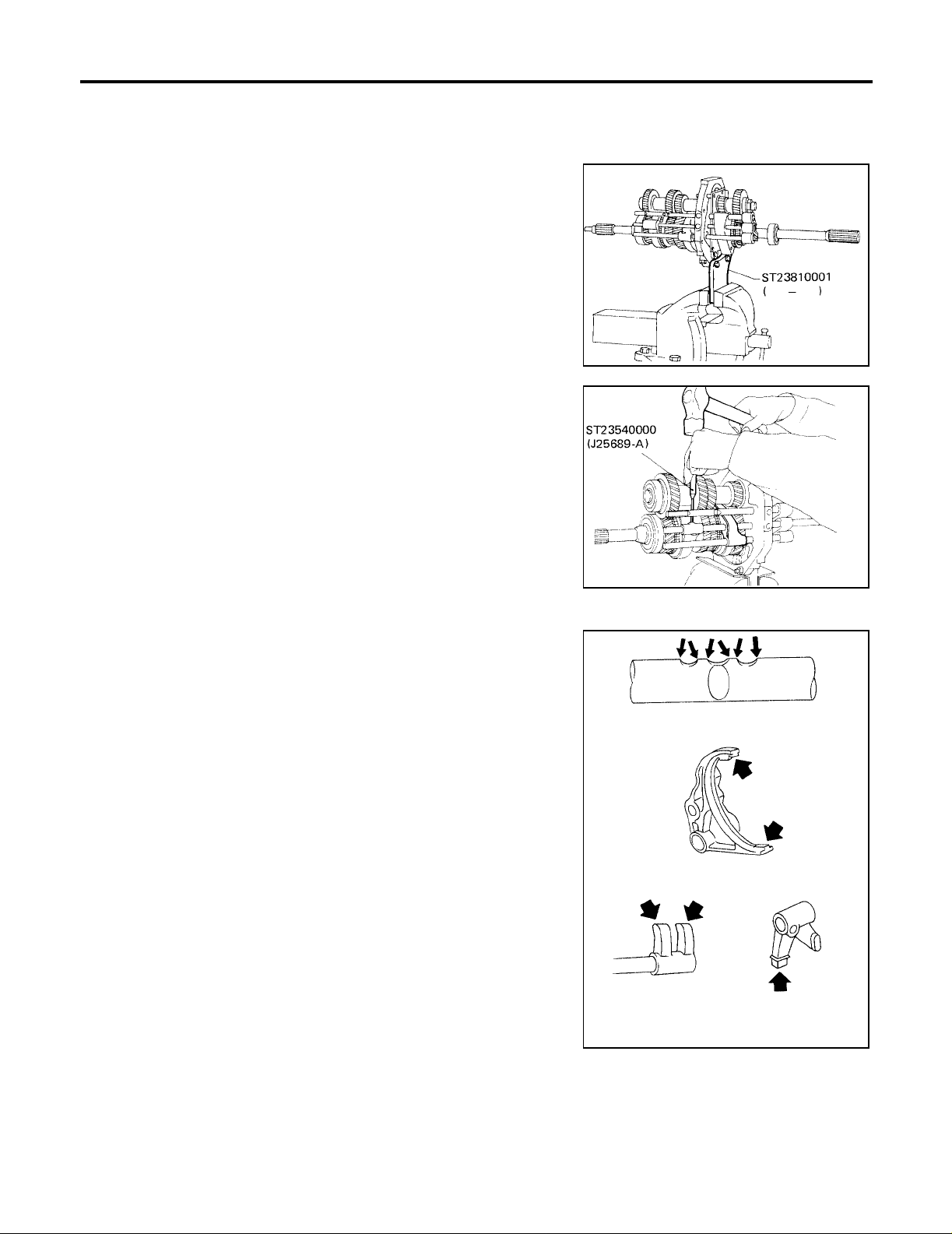
1. Set up Tool on adapter plate.
Tool number : ST23810001 ( — )
2. Remove striking rod from adapter pl ate.
3. Remove check ball plugs, check springs, and check balls.
NOTE:
Mark locations of interlock balls to ensure proper installation.
4. Drive out retaining pins. Then drive out fork rods and remove
interlock balls.
PFP:32982
ECS006IC
SMT545A
Inspection
● Check contact and sliding surfaces of fork rods for wear,
scratches, projecti on s an d ot h er dama ge.
SMT984
ECS006ID
MT-22
SMT075C
SHIFT CONTROL COMPONENTS
[FS5W71C]
Assembly
1. Install fork rods, interlock plunger, interlock balls and check
balls.
2. Install 1st and 2nd shift fork, then drive in retaining pin.
3. Install 3rd and 4th shift fork, then drive in retaining pin.
ECS006IE
SMT992-A
SMT989
A
B
MT
D
E
F
G
H
4. Install overdrive and reverse shift fork, then drive in retaining
pin.
I
J
K
SMT990
L
M
SMT991
MT-23
GEAR COMPONENTS
[FS5W71C]
GEAR COMPONENTS
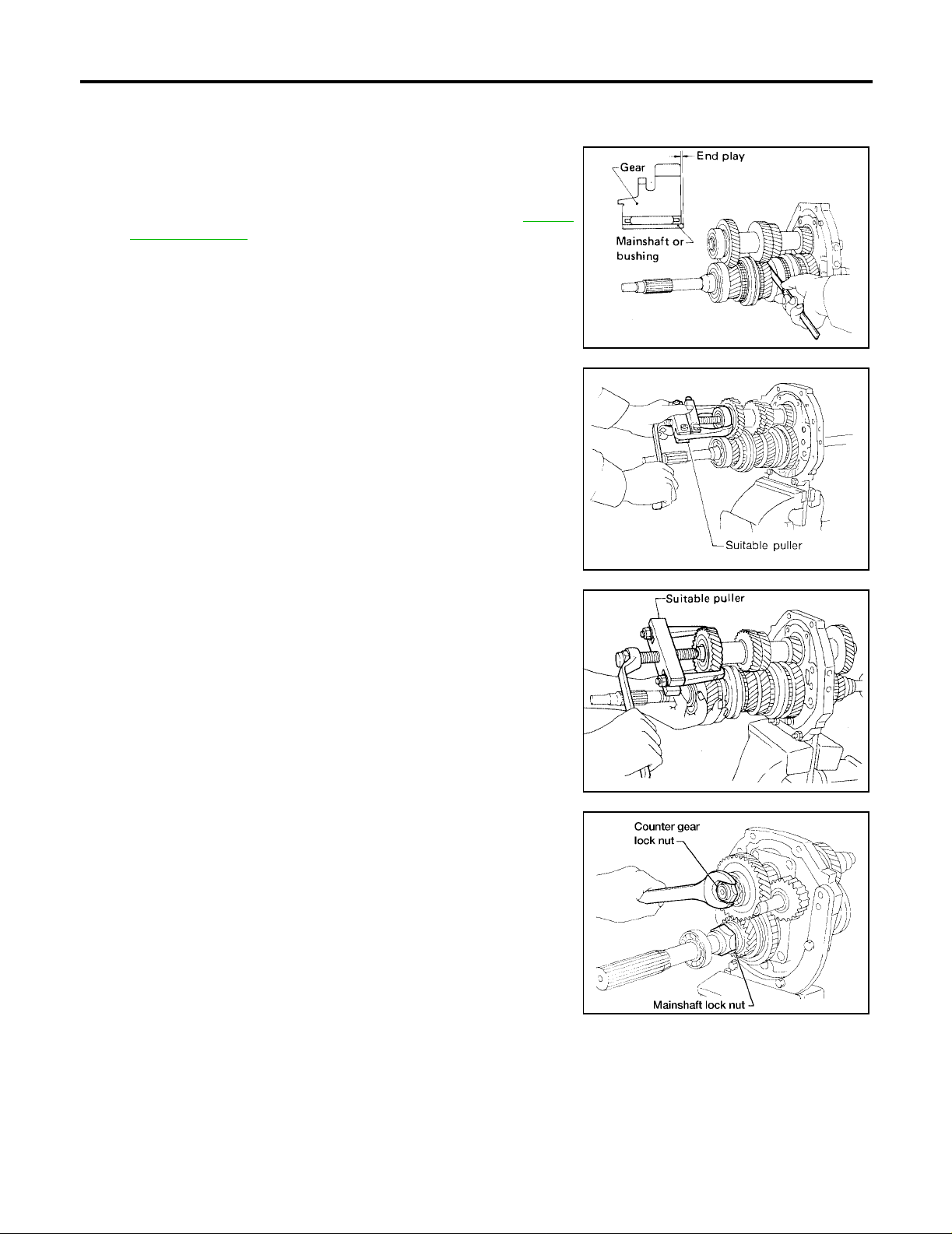
Disassembly
1. Before disassembly, measure the end play of each gear.
● If end play is no t within the specified limit, d isassemble and
inspect the parts.
● Replace any part whic h is worn or da maged. R efer to MT-35,
"Gear End Play" .
2. Mesh 2nd and reverse gear, then remove counter gear front
bearing using a suitable puller.
3. Remove counter gear s nap rin g, then r emove s ub-ge ar brac ket,
sub-gear spring and sub-gear.
PFP:31460
ECS006IF
SMT025
4. Remove counter drive gear together with main drive gear
assembly using a suitable puller. Remove woodruff keys and
pilot bearing.
● When removing main drive gear assembly, be careful not to
drop pilot bear ing or baulk ring.
5. Remove mainshaft front snap ring, then remove 3rd and 4th
synchronizer assembly, 3rd main gear and needle bearing using
suitable puller.
6. Disassemble parts at rear of ad apter plate as follows:
a. Release staking o n both counter gear and main shaft lock nuts,
then loosen both nuts.
Mainshaft lock nut : Left-hand thread
SMT174A
SMT162A
WCIA0181E
MT-24
GEAR COMPONENTS
[FS5W71C]
b. Remove overdrive counter gear together with counter gear rear
end bearing using a suitable puller.
c. Remove reverse counter ge ar an d reve rs e co un ter ge ar spacer.
d. Remove snap rings from reverse idler shaft, then remove
reverse idler gear, sub-gear, sub-gear spring, sub-gear bracket,
steel ball, reverse idler thrust washer and reverse idler gear
bearing.
SMT547A
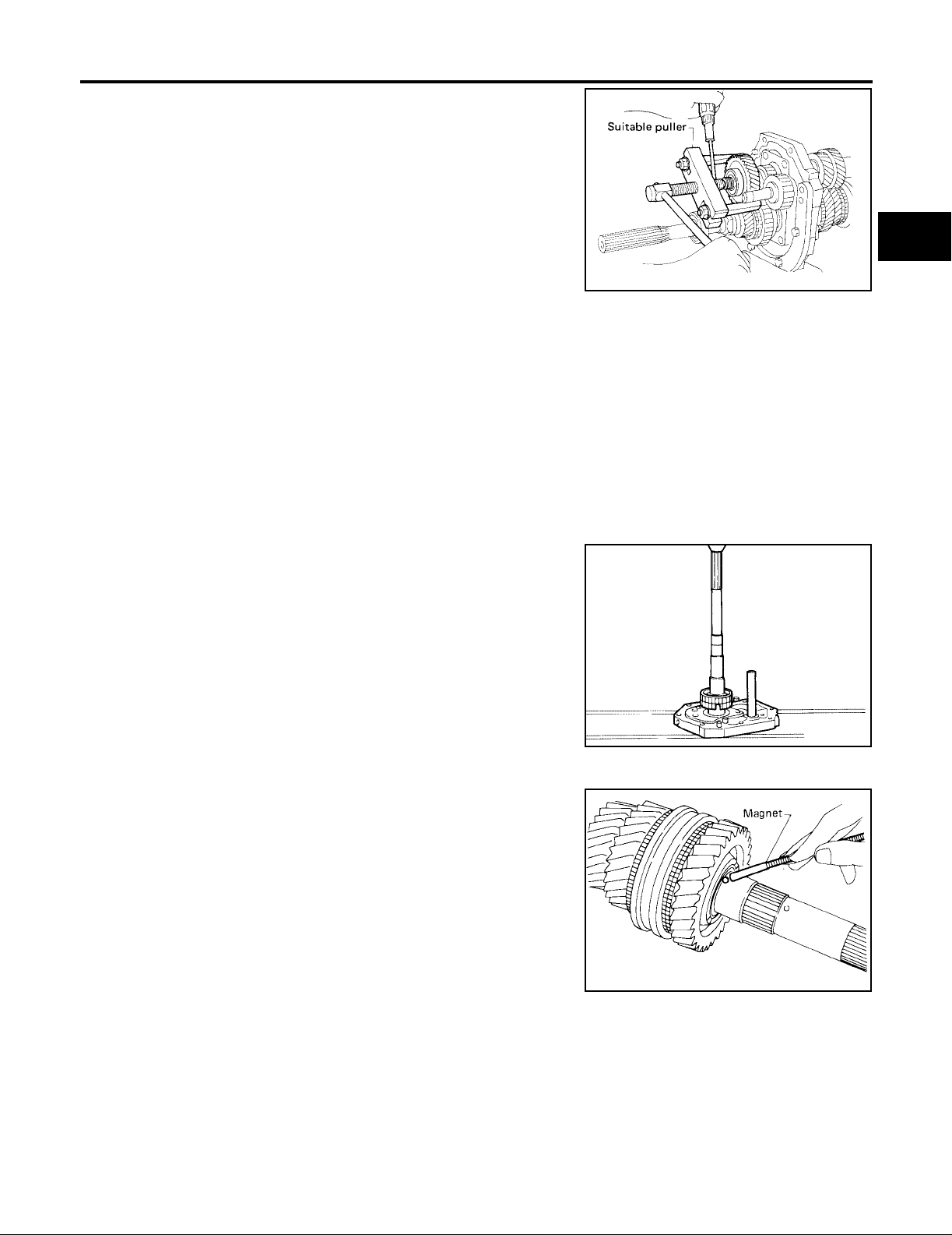
e. Remove overdrive mainshaft bearing snap ring and pull out overdrive mainshaft bearing using Tool, then
remove snap ring.
A
B
MT
D
Tool number : (J-26349-A), (J-25726-B)
f. Remove mainshaft lock nut.
g. Remove speedometer drive gear and steel ball.
h. Remove thrust w asher, steel roller, roller bearing and washer.
i. Remove overdrive main gear, needle bearing and overdrive baulk ring.
j. Remove counter gear by tapping on rear end of counter gear.
k. Press out overdrive gear bushing and overdrive & reverse synchronizer assembly.
l. Remove reverse main gear and needle bearing.
m. Press out reverse main gear bushing.
n. Remove mainshaft by tapping on rear end of mainshaft.
7. Remove 1st gear thrust washer, steel ball, 1st main gear and
needle bearing and 1st and 2nd synchronizer assembly.
● Be careful not to lose steel ball.
SMT554A
E
F
G
H
I
J
K
L
M
MT-25
SMT383A
GEAR COMPONENTS
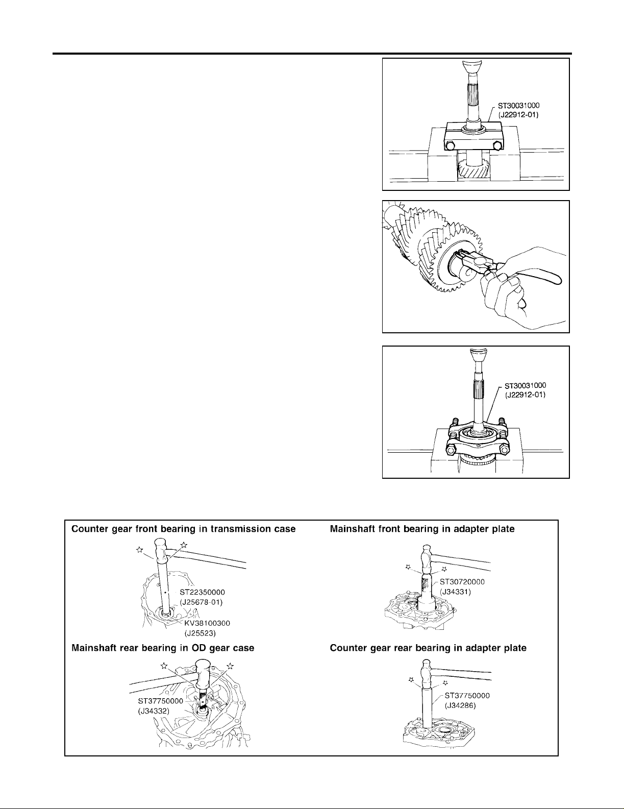
8. Press out 1st gear bushing together with 2nd main gear using
Tool.
Tool number : ST30031000 (J22912-01)
9. Remove 2nd gear needle bearing.
10. Remove main drive gear ball bearing.
a. Remove main drive gear ball bearing snap ring.
b. Remove main drive gear ball bearing using Tool.
Tool number : ST30031000 (J22912-01)
11. Disassemble adapter plate components.
a. Remove bearing retainer.
b. Remove oil gutter
c. Remove reverse idler shaft.
d. Remove main shaft ball bearing and counter rear be aring using
suitable tool.
[FS5W71C]
TM049A
SMT420A
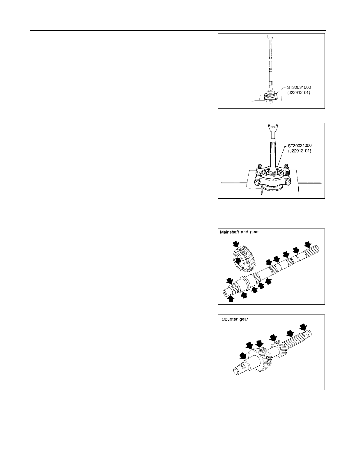
Inspection
GEARS AND SHAFTS
● Check shafts for cracks, wear and bending.
● Check gears for excessive wear, chips and cracks .
ECS006IG
SMT386A
MT-26
SMT550A

GEAR COMPONENTS
SYNCHRONIZERS
● Check spline portion of coupling sleeves, synchronizer hubs,
and gears for wear, chips, and cracks.
● Check baulk ring s for cracks and deformatio n.
● Check shifting inserts for wear and deformation.
[FS5W71C]
A
B
MT
● Check insert spread springs for deformation.
● Measure baulk ring wear.
1. Measure clearance between baulk ring and gear. Refer to MT-
36, "Clearance Between Baulk Ring and Gear" .
● If the clearance is less than the wear limit, replace baulk ring.
BEARINGS
● Make sure all bearings roll freely and are free from noise,
cracks, pitting or wear.
SMT427C
SMT140
D
E
F
G
H
I
J
K
Assembly
1. Install bearings into case components.
Tool numbers
Mainshaft ball bearing : ST30720000 (J25405)
Counter rea r bearing : ST33200000 (J26082)
MT-27
AMT185
SMT418A
ECS006IH
L
M

GEAR COMPONENTS
2. Assemble adapter plate parts.
a. Install oil gutter on adapter plate and expand on rear side.
b. Insert reverse idler shaft, then install bearing retainer.
c. Tighten bearing retainer screws, then stake each one at two
points.
Bearing retainer screws : 19 - 25 (1.9 - 2.5 kg-m,
14 - 18 lb-ft)
[FS5W71C]
SMT778C
3. Instal l main drive gear ball bear ing.
a. Press main drive gear ball bearing using Tool.
Tool number : ST30613000 (J25742-3)
b. Select and install proper main drive ball bearing gear snap ring
to achieve proper clearance of groove. Refer to MT-36 , "
MAIN
DRIVE GEAR BALL BEARING SNAP RING" .
Main drive ball bearing
: 0 - 0.13 mm (0 - 0.0051 in)
gear snap ring groove
allowable clearance
SMT674C
SMT425A
SMT170D
4. Assemble synchronizers.
● Assemble the 1s t and 2nd synchronizer.
SMT054C
MT-28

GEAR COMPONENTS
● Check coupling sleeve and synchronizer hub orientation.
[FS5W71C]
A
B
MT
D
E
F
● Assemble the 3rd and 4th synchronizer.
SMT206C
G
H
I
J
K
L
M
WMT053
MT-29

GEAR COMPONENTS
● Assemble the o verdrive and reverse sync hronizer.
[FS5W71C]
5. Assemble front side components to mainshaft.
a. Instal l 2nd mai n gea r, 2nd main gear n eedle be ari ng an d 1st and
2nd synchronizer assembly; then press 1st gear bushing onto
the mainshaft.
b. Install 1st main gear.
c. Install steel ball and 1st gear thrust washer.
● Before installation, apply multi-purpose grease to steel ball
and to both sides of the 1st gear thrust washer.
SMT207CA
SMT752A
TM358
6. Install mainshaft and counter gear on adapter plate and main
drive gear on mainshaft as follows:
a. Press mainshaft assembly into adapter plate using Tool.
Tool number : KV31100401 ( — )
MT-30
TM439

GEAR COMPONENTS
[FS5W71C]
b. Press coun te r gear in to adapter plate using Tool.
Tool number : ST33200000 (J26082), KV31100401 ( — )
SMT750
c. Install 3rd main gear and needle bearing, then press 3rd and 4th synchronizer assembly onto mainshaft.
● Pay attention to the direction of 3rd and 4th synchronizer.
d. Install mainshaft front snap ring.
Select proper fr ont main shaft sna p ring to achiev e prope r clearance of groove. Refer to MT-36, "
RING" .
Mainshaft front snap
ring groove allowable
clearance
e. Apply ge ar oil to mainshaft pilot be aring and install it on main -
shaft.
MAINSHAFT FRONT SNAP
: 0 - 0.13 mm (0 - 0.0051 in)
TM441
A
B
MT
D
E
F
G
H
f. Press counter drive gear together with main drive gear using
Tool.
● Pay attention to the direction of counter drive gear.
Tool numbers : ST23860000 ( — ), KV31100401 ( — )
g. Install sub-gear and sub-gear bracket on counter drive gear and
then select proper counter gear snap ring that will minimize
clearance of groove in counter gear.
● Do not install sub-gear spring at this time. Refer to MT-36,
"COUNTER DRIVE GEAR SNAP RING" .
Counter gear snap ring
: 0 - 0.13 mm (0 - 0.0051 in)
groove allowable clearance
I
J
K
SMT412C
L
M
SMT201D
MT-31

GEAR COMPONENTS
h. Remove snap ring, sub-gear bracket and sub-gear from counter
gear.
i. Reinstall sub-gear, sub-gear spring, sub-gear bracket and
selected counter gear snap ring.
j. Press counter gear front bearing onto counter gear using Tool.
Tool number : ST22360002 (J25679-01),
KV31100401 ( — )
[FS5W71C]
SMT202D
7. Install rear side comp onents on mainshaft and cou nter gear as
follows:
a. Install sub-gear, sub-gear spring, sub-gear bracket, steel ball
and snap ring on the reverse idler gear.
b. Install reverse idler gear assemb ly, reverse idler thrus t washer,
snap ring and reverse idler gear bearing on the reverse idler
shaft.
c. Install reverse main gear bushing, ne ed le beari ng, reve rse mai n
gear and overdrive and reverse synchronizer to mainshaft.
● Pay attention to the direction of synchronizer hub.
TM443
AMT134
MT-32
SMT207CA

GEAR COMPONENTS
d. Install ov erdrive gear bushing to mainshaft using Tool.
Tool number : ST22350000 (J25678-01)
e. Install overdrive main gear and needle bearing to mainshaft.
f. Install reverse counter gear spacer, reverse counter gear and
overdrive counter gear to counter gear.
● OD main gear a nd OD counter ge ar should be h andled as a
matched set.
g. Install washer, roller bearing, steel roller and thrust washer.
h. Install steel ball and speedometer drive gear.
i. Tighten mainshaft lock nut temporarily.
● Always use new mainshaft lock nut.
[FS5W71C]
SMT531
A
B
MT
D
j. Install counter gear rear end bearing using Tool.
Tool number : ST2236002 (J25679-01)
8. Mesh 2nd and reverse gears, then tighten mainshaft lock nut
using Tool.
● Always use new mainshaft lock nut.
Mainshaft lock nut : 138 - 166 N·m (14.0 - 17.0 kg-m,
102 - 122 ft-lb)
Tool number : ST22520000 (J26348)
● Use the chart shown to determine the proper reading torque.
(Length of torque wrench vs. setting or reading torque)
Reference: F ormul a to co nvert tor que wren ch ind icat ion to the
true torque value:
T = (0.1 m (0.33 ft) + L) /L × C
If the specified torque is T kg-m (ft-lb), the torque wrench
scale indication C is determined using the following for m ula.
C = (T × L)/(0.1 m (0.33 ft) + L)
SMT043
SMT003A
E
F
G
H
I
J
K
L
M
MT-33
SMT004A

GEAR COMPONENTS
9. Tighten counter gear lock nut.
● Always use new lock nut.
Counter gear lock nut : 98 - 127 N·m (10.0 - 13.0 kg-m,
73 - 94 ft-lb)
10. Stake mainshaft lock nut and counter gear lock nut using a
punch.
11. Measure the end play of each gear.
12. Install sna p ri ng an d pres s on OD m ains haft bearin g us ing Tool,
then install snap ring. Refer to MT-37, "
ING SNAP RING" .
OD mainshaft bear-
: 0 - 0.14 mm (0 - 0.0055 in)
ing snap ring
groove allowable
clearance
OD MAINSHAFT BEAR-
[FS5W71C]
WCIA0182E
Tool number : (J-26349-A), (J-25726-B)
SMT025
MT-34

SERVICE DATA AND SPECIFICATIONS (SDS)
[FS5W71C]
SERVICE DATA AND SPECIFICATIONS (SDS) PFP:00030
General Specifications
ECS006II
A
Applied model
Transmission FS5W71C
Number of speed 5
Shift pattern
MT-SDS-2
Synchromesh type Warner
1st 3.592
2nd 2.246
Gear ratio
Mainshaft
(Number of teeth)
Countershaft gear
(Number of teeth)
Reverse idler gear (Number of teeth) 21
Oil capacity
(US pt, Imp pt)
Remarks
3rd 1.415
4th 1.000
OD 0.821
Reverse 3.657
Drive 21
1st 33
2nd 28
3rd 26
OD 21
Reverse 36
Drive 32
1st 14
2nd 19
3rd 28
OD 39
Reverse 15
Reverse synchronizer Installed
Sub gear Counter drive gear and reverse idler gear
KA24DE
2WD
2.0 (4-1/ 4, 3-1/2)
B
MT
D
E
F
G
H
I
J
K
L
M
Gear End Play
1st gear 0.31 - 0.41 (0.0122 - 0.0161)
2nd gear 0.11 - 0.21 (0.0044 - 0.0083)
3rd gear 0.11 - 0.21 (0.0044 - 0.0083)
Overdrive gear 0.24 - 0.41 (0.0095 - 0.0161)
MT-35
ECS006IJ
Unit: mm (in)

SERVICE DATA AND SPECIFICATIONS (SDS)
[FS5W71C]
Clearance Between Baulk Ring and Gear
1st & 2nd 1.20 - 1.60 (0.0473 - 0.0629)
Standard
Wear limit
2ND & 3RD BAULK RING
3rd & main drive 1.20 - 1.60 (0.0473 - 0.0629)
Overdrive 1.20 - 1.60 (0.0473 - 0.0629)
Reverse 1.10 - 1.55 (0.0433 - 0.0610)
1st & 2nd 0.80 (0.0315)
3rd & main drive 0.80 (0.0315)
Overdrive 0.80 (0.0315)
Reverse 0.70 (0.0276)
ECS006IK
Unit: mm (in)
Unit: mm (in)
SMT733C
Dimension Standard Wear limit
A 0.7 - 0.9 (0.028 - 0.035)
B 0.6 - 1.1(0.024 - 0.043)
Available Snap Rings
MAIN DRIVE GEAR BALL BEARING SNAP RING
Main drive gear ball bearing snap ring groove all ow abl e clear ance 0 - 0.13 (0 - 0.0051)
Thickness Part number*
1.87 (0.0736) 32204-78001
1.94 (0.0764) 32204-78002
2.01 (0.0791) 32204-78003
*Always check with the Parts Department for the latest parts information.
MAINSHAFT FRONT SNAP RING
Mainshaft front snap ring groove allowabl e cl ear anc e 0 - 0.18 (0 - 0.0071)
Thickness Part number*
2.4 (0.094) 32263-V5200
2.5 (0.098) 32263-V5201
*Always check with the Parts Department for the latest parts information.
0.2 (0.008)
ECS006IL
Unit: mm (in)
Unit: mm (in)
COUNTER DRIVE GEAR SNAP RING
Counter gear snap ring groove allowable cl ear ance 0 - 0.13 (0 - 0.0051)
Thickness Part number*
1.4 (0.055) 32215-E9000
MT-36
Unit: mm (in)

SERVICE DATA AND SPECIFICATIONS (SDS)
[FS5W71C]
1.5 (0.059) 32215-E9001
1.6 (0.063) 32215-E9002
*Always check with the Parts Department for the late st parts information.
OD MAINSHAFT BEARING SNAP RING
OD mainshaft bearing snap ring groove allow able cl ear ance 0 - 0.14 (0 - 0.0055)
Thickness Part number*
1.1 (0.043) 32228-20100
1.2 (0.047) 32228-20101
1.3 (0.051) 32228-20102
1.4 (0.055) 32228-20103
*Always check with the Parts Department for the late st parts information.
Available Shims
COUNTERSHAFT FRONT BEARING SHIM
Allowable clearance “A” from bearing surfa ce to transm i ssi on case 0 - 0.16 (0 - 0.0063)
Unit: mm (in)
ECS006IM
Unit: mm (in)
A
B
MT
D
E
F
G
H
“A” Thickness of shim Part number*
4.52 - 4.71 (0.1780 - 0.1854) Not necessary
4.42 - 4.51 (0.1741 - 0.1775) 0.1 (0.004) 32218-V5000
4.32 - 4.41 (0.1701 - 0.1736) 0.2 (0.008) 32218-V5001
4.22 - 4.31 (0.1662 - 0.1691) 0.3 (0.012) 32218-V5002
4.12 - 4.21 (0.1622 - 0.1657) 0.4 (0.016) 32218-V5003
4.02 - 4.11 (0.1583 - 0.1618) 0.5 (0.020) 32218 -V50 04
3.92 - 4.01 (0.1544 - 0.1578) 0.6 (0.024) 32218-V5005
*Always check with the Parts Department for the late st parts information.
SMT205D
I
J
K
L
M
MT-37
PREPARATION
[FS5R30A]
PREPARATION
Special Service Tools
The actual shapes of Kent-Moore tools may differ from those of spe ci al se rvice tools illustrated here.
Tool number
(Kent-Moore No.)
Tool name
ST23540000
(J25689-A)
Pin punch
NT442
ST30031000
(J22912-01)
Puller
NT411
ST33290001
(J34286)
Puller
Description
Removing and installing retaining pin
a: 2.3 mm (0.091 in) dia.
b: 4 mm (0.16 in) dia.
Removing 1st & 2nd synchronizer assembly
Removing counter gear rear thrust bearing
Removing main drive bearing
Inspecting baulk ring wear
a: 90 mm (3.54 in) dia.
b: 50 mm (1.97 in) dia.
Removing rear oil seal
a: 250 mm (9.84 in)
b: 160 mm (6.30 in)
PFP:00002
ECS006IN
ST33230000
( — )
Drift
ST22350000
(J25678-01)
Drift
KV38100300
(J25523)
Drift
ST30720000
1 (J34286)
2 (J34331)
Drift
NT414
Removing mainshaft and counter gear
a: 51 mm (2.01 in) dia.
b: 28.5 mm (1.122 in) dia.
NT084
Removing counter gear front bearing (Use
with KV38100300)
a: 34 mm (1.34 in) dia.
b: 28 mm (1.10 in) dia.
NT065
Removing counter gear front bearing (Use
with ST22350000)
Installing counter gear rear bearing
a: 54 mm (2.13 in) dia.
b: 32 mm (1.26 in) dia.
NT065
1 Removing mainshaft front bearing
2 Installing mainshaft front bearing
a: 77 mm (3.03 in) dia.
b: 55.5 mm (2.185 in) dia.
MT-38
NT115

PREPARATION
[FS5R30A]
Tool number
(Kent-Moore No.)
Tool name
ST33210000
1 (J25523)
2 (J25803-01)
Drift
ST30613000
(J25742-3)
Drift
ST37750000
1 (J34286)
2 (J34332)
3 (J34334)
4 (J25679-01)
Drift
ST22452000
(J34337)
Drift
NT084
NT073
NT065
Description
1 Installing counter gear front bearing
2 Installing front cover oil seal
a: 44 mm (1.73 in) dia.
b: 24.5 mm (0.965 in) dia.
Installing main drive gear bearing
a: 72 mm (2.83 in) dia.
b: 48 mm (1.89 in) dia.
1 Removing counter gear rear bearing
2 Installing OD gear bushing
2 Removing and installing mainsh aft rea r
bearing (4WD model)
2 Installing reverse cone
3 Installing reverse counter gear
4 Installing counter gear rear end bearing
a: 40 mm (1.57 in) dia.
b: 31 mm (1.22 in) dia.
Installing reverse synchronizer hub
Installing mainshaft rear bearing (2WD model)
a: 45 mm (1.77 in) dia.
b: 36 mm (1.42 in) dia.
A
B
MT
D
E
F
G
H
I
ST33400001
(J26082)
Drift
(J26349-3)
Puller leg
(J34328)
Puller
NT065
NT086
NT078
NT079
Installing rear oil seal
a: 60 mm (2.36 in) dia.
b: 47 mm (1.85 in) dia.
Installing mainshaft and counter gear
(Use with J34328)
Installing mainshaft and counter gear
(Use with J26349-3)
J
K
L
M
MT-39

Tool number
(Kent-Moore No.)
Tool name
(J26092)
Drift
(J34342)
Drift
ST33220000
(J25804-01)
Drift
PREPARATION
[FS5R30A]
Description
Installing sub-gear snap ring
a: 44.5 mm (1.752 in) dia.
b: 38.5 mm (1.516 in) dia.
NT065
Installing OD main gear
Installing reverse gear bushing
a: 44.5 mm (1.752 in) dia.
b: 40.5 mm (1.594 in) dia.
NT065
Installing mainshaft rear bearing
a: 37 mm (1.46 in) dia.
b: 22 mm (0.87 in) dia.
(J-26349-A)
Bearing Remover and Installer Set
(J-34286)
Rear Race Puller
(J-39856)
Gear and Bearing Removal Kit
Commercial Service Tool
NT084
Removing and installing mainsha ft bear ing
(Use with J-25726-B)
WMT065
Removing races
WMT066
Removing gears and bearings
WMT067
ECS006IO
Tool name Description
Puller Removing counter gear rear end bearing
Removing mainshaft rear bearing (2WD model)
Removing reverse synchronizer hub
Removing reverse counter gear
NT077
MT-40

NOISE, VIBRATION, AND HARSHNESS (NVH) TROUBLESHOOTING
[FS5R30A]
NOISE, VIBRATION, AND HARSHNESS (NVH) TROUBLESHOOTING PFP:00003
NVH Troubleshooting Chart
Use the chart below to help you find the cause of the problem. The numbers indicate the order of the inspection. If necessary, repair or replace these parts.
ECS006IP
A
B
Reference page
SUSPECTED PARTS
(Possible cause)
MA-35
MT-59
MT-63
MT-65
MT
D
E
F
G
H
I
Symptom
OIL (Level low)
OIL (Wrong)
OIL (Level too high)
GASKET (Damaged)
OIL SEAL (Worn or damaged)
O-RING (Worn or damaged)
CHECK PLUG RETURN SPRING AND CHECK BALL (Worn or damaged)
SHIFT FORK (Worn)
GEAR (Worn or damaged)
BEARING (Worn or damaged)
BAULK RING (Worn or damaged)
Noise 1 2 3 3
Oil leakage 3 1 2 2 2
Hard to shift or will not shift 1 1 2 2
Jumps out of gear 1 2 2
J
INSERT SPRING (Damaged)
K
L
M
MT-41

DESCRIPTION
[FS5R30A]
DESCRIPTION
Description
CROSS-SECTIONAL VIEW — 2WD MODEL
PFP:00000
ECS006IQ
MT-42
WCIA0183E

DESCRIPTION
[FS5R30A]
1. Release bearing sleeve 2. Front cover 3. Main drive gear
4. 3rd and 4th shift fork 5. Transmission case 6. 3rd and 4th coupling sleeve
7. Striking interlock 8. 3rd main gear 9. 2nd main gear
10. 1st main gear 11. OD main gear 12. Striking rod
13. Reverse shift fork 14. Shi f t lever 15. M ainshaft
16. Mainshaft rear bearing 17. C ounter gear rear end bearing 18. Reverse main gear
19. Rear extension 20. OD coun ter gear 21. Adapter plate
22. Mainshaft front bearing 23. Drain plug 24. 1st and 2nd coupling sleeve
25. Counter gear 26. Sub-gear 27. Counter gear front bearing
28. Main drive gear bearing 29. Main drive gear
A
B
MT
D
E
F
G
H
K
M
I
J
L
MT-43

DESCRIPTION
CROSS-SECTIONAL VIEW — 4WD MODEL
[FS5R30A]
MT-44
WCIA0184E

DESCRIPTION
[FS5R30A]
1. Release bearing sleeve 2. Front cover 3. Transmission case
4. Main drive gear bearing 5. Main drive gear 6. 3rd and 4th shift fork
7. 3rd and 4th coupling sleeve 8. 3rd main gear 9. Striking interlock
10. 2nd main gear 11. 1st and 2nd coupling sleeve 12. 1st main gear
13. Mainshaft front bearing 14. O D ma in ge ar 15. Rear ex ten si on
16. Reverse main gear 17. Striking rod 18 . Shift lever
19. Mainshaft 20. Counter gear rear end bea ring 21. OD counter gear
22. Adapter plate 23. Drain plug 24. Counter gear
25. Sub-gear 26. Counter gear front bearing
A
B
MT
D
E
F
G
H
K
M
I
J
L
MT-45

ON-VEHICLE SERVICE
[FS5R30A]
ON-VEHICLE SERVICE
Replacing Rear Oil Seal — 2WD Model
REMOVAL
1. Remove the pro peller shaf t. Refer to PR-8, "Removal and Instal-
lation" .
2. Remove rear oil seal using Tool.
● Always replace with a new rear oil seal once it has been
removed.
Tool number : ST33290001 (J25810-A)
INSTALLATION
1. Install new rear oil seal until it stops.
● Apply multi-purpose grease to seal lip of oil seal before install-
ing.
Tool number : ST33400001 (J26082)
2. Installation is in the reverse ord er of rem oval .
PFP:00000
ECS006IR
SMT479CA
Position Switch Check
Switch Gear position Continuity
Back-up lamp switch
Park/neutral position
(PNP) switch
Except reverse No
Except neutral No
SMT480CA
ECS006IS
Reverse Yes
Neutral Yes
MT-46
SMT981D

ON-VEHICLE SERVICE
[FS5R30A]
A
B
MT
D
E
F
AMT205
G
H
I
J
K
L
M
MT-47

TRANSMISSION ASSEMBLY
[FS5R30A]
TRANSMISSION ASSEMBLY
Removal and Installation
PFP:32010
ECS006IT
REMOVAL
CAUTION:
When removing the M/T assembly from engine, first remove the crankshaft position sensor (OBD)
from the M/T assembly. Be careful not to damage sensor edge.
2WD Model
1. Remove battery nega tiv e ter mi na l.
2. Remove shift lever.
3. Remove crankshaft position sensor (OBD) from upper side of
transmission case.
4. Remove operating cylinder from transmission. Refer to CL-5,
"Components" .
5. Disconnect vehicle speed sensor, back-up lamp switch, heated
oxygen sensor (rear) and park/neutral position (PNP) switch
harness connectors.
6. Remove starter motor. Refer to SC-23, "
MODELS" .
7. Remove propeller shaft. Refer to PR-8, "
tion" .
● Insert plug into rear oil seal aft er rem ov in g prope lle r sha ft.
● Be careful not to damage spline, sleeve yoke and rear oil seal when removing propeller shaft.
8. Remove gussets from transmission or engine.
9. Remove exhaust tube mo un tin g bra cket from tran s mi ssio n. Refe r to EX -3, "
10. Support ma nu al trans mi ss io n with a jack.
11. Remove rear mounting member. Refer to EM-127, "
12. Lower manual transmission.
VG33E AND VG33ER
Removal and Installa-
Removal and Installation" .
Removal and Installation" .
AMT189
SMT099A
MT-48

TRANSMISSION ASSEMBLY
WARNING:
Support manual transmission together with transfer while removing it.
[FS5R30A]
A
B
MT
D
E
F
4WD Model
1. Disconnec t the ba tte ry ne ga tiv e term in al .
2. Remove shift lever from transmission and control lever from
transfer.
3. Remove clutch operating cylinder from transmission. Refer to
CL-5, "
4. Disconnect the vehicle speed sensor, back-up lamp switch,
heated oxygen sensor (rear) and Park/neutral position (PNP)
switch harness connectors.
5. Remove the starter motor. Refer to SC-23, "
VG33ER MODELS" .
6. Remove front and rear propeller shafts. Refer to PR-8,
"Removal and Installation" .
● Insert plug into rear oil seal after removing propeller shaft.
● Be careful not to damage spline, sleeve y oke and rear oil seal when removing propeller shaft .
7. Remove exhaust tube mounting bracket from transmission. Refer to EX-3, "
8. Remove front exhaust tubes and center pipe.
9. Remove the torsion bars and mounts. Refer to FSU-14, "
10. Remove the rear torsion bar cross member.
11. Remove the gussets from the transmission or engine.
12. Support the manual transmission with a jack.
13. Remove rear mounting member. Refer to EM-127, "
14. Lower manual transmission.
WARNING:
Support manual transmission together with transfer while removing it.
15. Remove crankshaft position sensor (OBD) from upper side of transmis sion case.
16. Remove transmission bolts.
WARNING:
Support manual transmission together with transfer while removing it.
Components" .
VG33E AND
Removal and Instal la tio n" .
TORSION BAR SPRING" .
Removal and Ins tallation" .
AMT203
SMT558A
G
H
I
J
K
L
M
MT-49

TRANSMISSION ASSEMBLY
INSTALLATION
● Tighten the bolts securing the transmission to the specified
torques in the chart below.
[FS5R30A]
Bolt No. Tightening torque N·m (kg-m, ft-lb)
1 39 - 49 (4.0 - 5.0, 29 - 36) 65 (2.56)
2 39 - 49 (4.0 - 5.0, 29 - 36) 58 (2.28)
3 29 - 39 (3.0 - 4.0, 22 - 29) 20 (0.79)
4 (Sta rte r spacer
and cover plate)
● Installation is in the reverse order of removal .
29 - 39 (3.0 - 4.0, 22 - 29) 25 (0.98)
mm (in)
WCIA0185E
MT-50

TRANSMISSION ASSEMBLY
[FS5R30A]
Overhaul
CASE COMPONENTS
ECS006IU
A
B
MT
D
E
F
G
H
K
M
I
J
L
MT-51
WCIA0187E

TRANSMISSION ASSEMBLY
1. Back-up lamp switch 2. Park/neutral position (PNP) swi t ch 3. Control housing bolts
4. Control housing 5. Plug 6. Clip
7. Dust cover 8. Rear oil seal 9. Rear extension
10. Rear extension bolt 11. Bearing retainer bolt 12. Slide ball bearing
13. Control housing bolt 14. Washer 15. Control housing
16. Baffle plate 17. OD gear case bolt 18. OD gear ca se
19. Back-up lamp switch 20. Drain plug 21. Front cover oil seal
22. Front cover bolt 23. Washer 24. Ball pin
25. Front cover 26. Gasket 27. Slide ball bearing
28. Transmissio n case 29. Filler plug 30. Air breath er
31. A dap te r plate 32. Bearing retainer
[FS5R30A]
MT-52

GEAR COMPONENTS
TRANSMISSION ASSEMBLY
[FS5R30A]
A
B
MT
D
E
F
G
H
K
M
I
J
L
MT-53
WCIA0188E

TRANSMISSION ASSEMBLY
[FS5R30A]
1. Main drive bearing snap ring 2. Main drive gear bearing snap ring 3. Main drive gear bearing
4. Main drive gear 5. Pilot bearing 6. Spacer
7. Mainshaft front snap ring 8. 4th baulk ring 9. 3rd and 4th coupling sleeve
10. Shifting insert 11. Spread spring 12. 3rd and 4th synchronizer hub
13. 3rd outer baulk ring 14. Synchronizer cone 15. 3rd inner baulk ring
16. 3rd main gear 17. 3rd gear needle bearing 18. Steel ball (For 1st gear washer)
19. Mainshaft 20. Co unt er gea r front bear i ng 21. Counter gear front bearing shim
22. S ub- gear bracket 23. Sub-gear spring 24. Sub-gear
25. Steel ball 26. Counter gear 27. Counter gear rear thrust bearing
28. 1st main gear with sub-gear
(VG33ER)
31. 1st gear needle bearing 32. 1st main gear without sub-gear
34. 1st and 2nd coupling sleeve 35. 1st an d 2nd synchronizer hub 36. 2nd outer baulk ring
37. 2nd inner baulk ring 38. 2nd main gear 39. Sub-gear snap ring
40. Counter gear front bearing
29. 1st gear washer 30. 1st gear bushing
33. 1st baulk ring
(VG33E)
MT-54

TRANSMISSION ASSEMBLY
[FS5R30A]
A
B
MT
D
E
F
G
H
K
M
I
J
L
MT-55
WCIA0189E

TRANSMISSION ASSEMBLY
[FS5R30A]
1. Mainshaft front bearing 2. Mainshaft front bearing snap ring 3. OD main gear
4. Speedometer drive gear (2WD
model)
7. Reverse gear needle bearings 8. Reverse syn chr oni zer hu b 9. Reverse coupling sleeve
10. Mainshaft spacer 11. Mainshaft rear bearing 12. Mainshaft C-ring
13. C -r ing hol der 14. Mainshaft rear snap ring 15. Counter gear rear snap ring
16. C ounter gear rear end bearing 17. Reverse counter gear 18. OD baulk ring
19. Reverse baulk ring 20. Reverse cone 21. Sprin g ins ert
22. O D coupl ing sl eeve 23. OD cou nte r gea r 24. OD gear needle bearing
25. O D gear bushi ng 26. Counter gear rear bea ring 27. Retaining pin
28. Reverse idler shaft 29. Reverse idle r need le bearings 30. Reverse idler ge ar (wit hout sub-
31. Reverse idler rear thrust washer 32. Reverse idler gear (with sub-gear)
34. S ub- gear spring 35. Steel ball 3 6. Sub-gea r bra cket
37. Snap ring
5. Reverse gear bushing 6. Reverse main gear
gear) (VG33E model)
33. Sub-gear
(VG33ER model)
MT-56

TRANSMISSION ASSEMBLY
SHIFT CONTROL COMPONENTS (2/4WD MODELS)
[FS5R30A]
A
B
MT
D
E
F
G
H
K
M
I
J
L
MT-57
WCIA0190E

TRANSMISSION ASSEMBLY
1. Snap ring 2. Socket 3. Spring
4. Shift knob 5. Shift lever 6. Upper boot retainer
7. Boot 8. Low er boot retainer 9. Control housing bolt
10. Washer 11. Control housing 12. Bushing
13. Return spring 14. Check ball 15. Select check plunger
16. Select check spring (small) 17. Select check spring (large) 1 8. Select chec k plu g
19. Select check spring 20. Re taining pin 21. Guide plate bolt
22. G ui de pl at e 23. Striking arm 24. O -r in g
25. Reverse check sleeve 26. Reverse check sleeve bolt 27. OD rod bracket
28. O D shi ft fork 29. OD fork rod 30. 1st and 2nd shift fork
31. Striking interlock 32. Striking lever 33. 3rd and 4th shift fork
34. Stopper ring 35. Interlock stopper bolt 36. Interlock stopper
37. Striking rod 38. OD and reverse fork rod 39. Reverse shift fork
40. Check ball 41. Check spring 42. Check ball plug
[FS5R30A]
MT-58
CASE COMPONENTS
[FS5R30A]
CASE COMPONENTS PFP:32100
Disassembly
1. Remove check ball plug, check spring and check ball. Then
remove interl oc k sto pper.
● If interlock assembly is removed as a unit, the check ball can
fall into transmissio n cas e .
● Be careful not to lose check ball.
2. Remove control housing, return spring and check ball.
● Be careful not to lose check ball.
ECS006IV
SMT366A
A
B
MT
D
E
F
G
3. Drive out retaining pin from striking arm using Tool.
Tool number : ST23540000 (J25689-A)
4. Remove rear extension (or OD gear case) together with striking
arm by tapping lightly.
SMT367A
SMT368A
H
I
J
K
L
M
MT-59
SMT135C

CASE COMPONENTS
5. Remove fron t cover and gasket.
6. Remove stopper ring and main drive bearing snap ring.
[FS5R30A]
SMT370A
7. Remove tran smission case by tappi ng lightly.
8. Remove counter gear front bearing shim and counter gear front thrust washer.
9. Remove spacer from between main drive gear and mainshaft.
10. Remove front cover oil seal using a screwdriver.
SMT371A
SMT372A
MT-60
SMT392A

CASE COMPONENTS
[FS5R30A]
Assembly
1. Install front cover oil seal using Tool.
● Apply multi-purpose grease to seal lip.
Tool number : ST33210000 (J25803-01)
2. Install selecte d counter gear front bearing shim onto transm ission case.
● Apply multi-purpose grease to counter gear front bearing
shim.
3. Apply sealant to mating surface of tran smission case.
● Use Genuine Anaerobic Liquid Gasket or equivalent. Refer to
MA-12, "
4. Install gear assembly onto transmission case.
5. Install check ball and check spring into interlock stopper.
● Apply multi-purpose grease to check ball.
RECOMMENDED FLUIDS AND LUBRICANTS" .
ECS006IW
SMT393A
SMT588A
A
B
MT
D
E
F
G
H
6. Install interlock stopper assembly and then tighten check ball
plug.
● Apply sealan t to thread of check ball plug.
● Use Genuine Anaerobic Liquid Gasket or equivalent. Refer to
MA-12, "
RECOMMENDED FLUIDS AND LUBRICANTS" .
Interlock stopper bolt : 32 - 42 N·m (3.2 - 4.3 kg-m,
24 - 31 lb-ft)
Check ball plug : 32 - 42 N·m (3.2 - 4.3 kg-m,
24 - 31 lb-ft)
7. Install stopper ring and main drive bearing snap ring.
I
J
K
SMT460A
L
M
SMT371A
MT-61

CASE COMPONENTS
8. Install front cover and gasket.
● Apply sealant to thread of 3 bolts shown.
● Use Genuine Anaerob ic Liqu id Gask et or equiv alen t. Refer to
MA-12, "
Front cover bolts : 16 - 21 N·m (1.6 - 2.1 kg-m,
9. Apply sealant to mating surface of adapter plate.
● Use Genuine Anaerob ic Liqu id Gask et or equiv alen t. Refer to
MA-12, "
10. Install rear extension or (OD gear case) together with striking
arm.
Rear extension bolts
(OD gear case bolts)
RECOMMENDED FLUIDS AND LUBRICANTS" .
12 - 15 lb-ft)
RECOMMENDED FLUIDS AND LUBRICANTS" .
: 32 - 42 N ·m (3 .2 - 4.3 kg- m,
24 - 31 lb-ft)
[FS5R30A]
SMT459A
11. Install retaining pin into striking arm using Tool.
Tool number ST23540000 (J25689-A)
12. Install check ball and return spring and th en apply sealant and
install control housing.
● Use Genuine Anaerob ic Liqu id Gask et or equiv alen t. Refer to
MA-12, "
RECOMMENDED FLUIDS AND LUBRICANTS" .
SMT461A
SMT368A
SMT462A
13. Tighten control housing bolts.
Bolt head size
A bolts : 12 mm (0.47 in)
B bolts : 13 mm (0.51 in)
Control housing
bolts
: 16 - 20 N·m (1.6 - 2.1 kg-m,
12 - 15 lb-ft)
SMT572A
MT-62

SHIFT CONTROL COMPONENTS
[FS5R30A]
SHIFT CONTROL COMPONENTS PFP:32982
Disassembly
1. Mount adapter plate on vise using copper plates to protect
adapter plate.
2. Remove OD and reverse fork rod.
3. Drive out retaining pin from striking lever using Tool.
Tool number : ST23540000 (J25689-A)
4. While pull ing out strikin g rod, remove str iking lever an d striking
interlock. Then remov e 1st and 2nd, 3rd and 4th, and reverse
shift forks.
ECS006IX
SMT373A
A
B
MT
D
E
F
G
5. Drive out retaining pin from OD shif t fork using Tool.
Tool number : ST23540000 (J25689-A)
6. Pull out OD fork rod and the n r emov e OD sh ift fork.
Inspection
● Check contact surfac e and sliding surface for wear, scratches,
projections or other damage.
Assembly
1. Install OD fork rod and OD shift fork. Then i nstall retaining pin
into OD shift fork.
SMT374A
H
I
J
ECS006IY
K
L
M
SMT398A
ECS006IZ
2. Install 1st and 2nd, 3rd and 4th, and reverse shift forks onto coupling sleeve.
MT-63
SMT457A

SHIFT CONTROL COMPONENTS
3. Install striking rod into hole of shift forks, striking lever and interlock and then i nstall retaining pin into striking lever using Tool.
● Make sure that striking rod moves smoothly.
Tool number : ST23540000 (J25689-A)
4. Install OD and reverse fork rod.
● Apply sealant to thread of O D and rev ers e fork rod bolt.
[FS5R30A]
OD and reverse fork rod
bolt
: 25 - 29 N·m (2.5 - 3.0 kg-m,
19 - 21 lb-ft)
SMT374A
MT-64

GEAR COMPONENTS
[FS5R30A]
GEAR COMPONENTS PFP:31460
Disassembly
1. Before removi ng gear s a nd sh af t s , me as ur e eac h g ea r en d pl a y.
Refer to MT-81, "
● If not within specification, disassemble and check contact sur-
face of gear to hub, washer, bushing, needle bearing and
shaft.
2. Remove rear side components on mainshaft and counter gear.
a. Remove rev ers e coupling sleeve.
Gear End Play" .
ECS006J0
SMT376A
A
B
MT
D
E
F
G
b. Remove mai nshaft rear snap ring and counter gear rear snap
ring.
c. Remove C-ring holder and mainshaft C-rings from mainshaft.
Use punch and hammer to remov e C -rin gs.
d. Remove counter gear rear end bearing using a puller.
e. Remove reverse idler thrust washer and reverse idler gear
(VG33E model) or snap ring, sub-gear bracket, steel ball, subgear spring, sub-gear and reverse idler (VG33ER model) and
reverse idler needle be ari ng s.
SMT463A
SMT377A
H
I
J
K
L
M
f. Remove mainshaft rear bearing (2WD model) using Tools.
Tool number : J-26349-A, J-25726-B
g. Remove mainshaft spacer.
MT-65
SMT378A

GEAR COMPONENTS
h. Remove reverse mai n gear together wi th mainshaft spacer an d
reverse synchronizer hub using a puller. Then remove reverse
gear needle bearing s.
i. Remove reverse counter gear using a puller.
j. Remove OD coupling sleeve together with OD baulk ring,
reverse baulk ring and spring inserts.
[FS5R30A]
SMT380A
k. Remove reverse gear bushing using a puller.
l. Remove speedometer drive gear (2WD model).
m. Remove OD gear bushing, OD gear needle bearing, OD counter
gear and reverse cone using puller.
SMT773A
SMT770A
MT-66
SMT771A

GEAR COMPONENTS
3. Press out mainshaft and counter gear alternately using Tool.
Tool number : ST33230000 ( — )
[FS5R30A]
A
B
MT
D
E
F
AMT174A
G
4. Remove front side components on mainshaft.
a. Remove 1st gear washer and steel ball.
● Be careful not to lose steel ball.
b. Remove 1st main gear and 1st gear needle bearing.
c. Press out 2nd main gear together with 1st gear bushing, 2nd
gear needle bearing and 1st and 2nd synchronizer assembly
using Tool.
Tool number : ST30031000 (J22912-01)
d. Remove mainshaft front bearing snap ring.
e. Press out 3rd main gear together with 3rd and 4th synchronizer
assembly and 3rd gear needle bearing.
H
I
J
SMT383A
K
L
M
SMT482C
MT-67
SMT385A
GEAR COMPONENTS
5. Remove fron t side components on counter gear.
a. Remove counter gear rear thrust bearing using Tool.
Tool number : ST30031000 (J22912-01)
b. Remove sub-g ear snap ring, sub-gear bracket, sub-gear s pring,
sub-gear and steel ball.
[FS5R30A]
SMT404A
6. Remove main drive gear bearing.
a. Remove main drive gear snap ring.
b. Press out main drive gear bearing using Tool.
Tool number : ST30031000 (J22912-01)
c. Remove pilot bearing.
7. Remove front bearing snap ring from adapter plate.
8. Remove bearings from case components using Tool.
SMT470A
SMT420A
MT-68
AMT173

GEAR COMPONENTS
[FS5R30A]
Tool numbers
Counter gear front bearing : ST22350000 (J25678-01),
KV38100300 (J25523)
Mainshaft front bearing : ST30720000 (J34331)
Mainshaft rear bearing : ST37750000 (J34332)
Counter gear rear bearing : ST37750000 (J34286)
Inspection
GEARS AND SHAFTS
● Check shafts for cracks, wear or bending.
● Check gears for exc essive wear, chips or cracks.
ECS006J1
SMT386A
A
B
MT
D
E
F
G
H
SYNCHRONIZERS
● Check spline portion of coupling sleeves, hubs, and gears for
wear or cracks.
● Check baulk rings for cracks or deformation.
● Check shifting inserts for wear or deformation.
● Check insert springs for deformation.
● Measure wear of main drive, 1st (VG33E model) and OD baulk
rings. Refer to MT-81, "
and Gear" .
● If the clearance is smaller than the wear limit, replace baulk ring.
Clearance Between Single Baulk Ring
I
J
SMT423A
K
L
M
SMT427C
MT-69
SMT140

GEAR COMPONENTS
● Measure wear of 1st, 2nd and 3rd double baulk rings.
● 1st, 2nd and 3rd double baulk rings: VG33ER model.
2nd and 3rd double baulk rings: VG33E model.
– Place baulk rings in position on synchronizer cone.
– Wh ile holding baulk rings ag ainst syn chronizer con e as far as it
will go, measure dimensions “A” and “B”.
Standard
Dimension "A" : 0.7 - 0.9 mm (0.028 - 0.035 in)
Dimension "B" : 0.6 - 1.1 mm (0.024 - 0.043 in)
Wear limit : 0.2 mm (0.008 in)
● If dimension “A” or “B” is smaller than the wear limit, replace
outer baulk ring, inner baulk ring and synchronizer cone as a set.
● Measure wear of reverse baul k r ing .
– Place baulk ring in posit ion on reverse cone.
– While holding baulk ring ag ains t r ev ers e con e as far as it wil l go,
measure dimension “A” with dial indicator.
[FS5R30A]
WMT049
WMT050
Standard
Dimension “A” : Standard 0.35 to 0.95 mm
(0.0119 to 0.0295 in)
Wear limit : 1.1 mm (0.043 in)
– If dim e ns io n “A” is larger than the wear l imit, replace baulk ring.
BEARINGS
● Make sure bearings roll freely and are free from noise, crack,
pitting or wear.
Assembly
SMT424A
SMT418A
ECS006J2
MT-70

GEAR COMPONENTS
1. Install bearings into case components.
Tool numbers
Counter gear front bearing : ST33210000 (J25523)
Mainshaft front bearing : ST30720000 (J34331)
Mainshaft rear bearing : ST33220000 (J25804-01)
Counter gear rear bearing : KV38100300 (J25523)
2. Install mainshaft front bearing snap ring into adapter plate.
3. Install be aring retainer.
[FS5R30A]
A
B
MT
D
E
F
AMT172
G
H
I
Bearing retainer bolt : 16 - 20 N·m (1.6 - 2.1 kg-m,
12 - 15 lb-ft)
4. Install main drive gear bearing.
a. Press main drive gear bearing using Tool.
Tool number : ST30613000 (J25742-3)
b. Install pilot bearing.
c. Select proper main drive ge ar s nap ri ng t o min imiz e clear ance of
groove. Refer to MT-82, "
Main drive gear
MAIN DRIVE GEAR SNAP RING" .
: 0 - 0.1 mm (0 - 0.00 3 i n)
snap ring groove
allowable clearanc e
d. Install selected main drive gear snap ring on main drive gear.
J
K
L
M
SMT425A
MT-71
SMT426A

GEAR COMPONENTS
5. Install components on counter gear.
a. Instal l sub- gea r, sub-gear spri ng, s ub-ge ar b racke t and sub-g ear
snap ring.
● When installing sub-gear snap ring, tap sub-gear snap ring
into positio n on counter gear using Tool.
Tool number : (J26092)
b. Install counter gear rear thrust bearing using a brass drift.
[FS5R30A]
SMT577A
6. Install front side components on mainshaft.
a. Assemble 1st and 2nd synchronizer.
b. Assemble 3rd and 4th synchronizer.
SMT405A
SMT614B
SMT615B
c. Press on 3rd and 4th synchronizer assembly together with 3rd
main gear and 3rd gear needle bearing.
● Pay attention to direc tio n of sy nc hronizer assembly.
MT-72
SMT399A

GEAR COMPONENTS
d. Select proper mainshaft front bearing snap ring to minimize
clearance of groove. Refer to MT-82, "
BEARING SNAP RING" .
MAINSHAFT FRONT
[FS5R30A]
A
Mainshaft front bear-
: 0 - 0.1 mm (0 - 0.003 in)
ing snap ring groove
allowable clearanc e
e. Install selected mainshaft front bearing snap ring on mainshaft.
f. Press on 1st and 2nd sync hronizer asse mbly together with 2nd
main gear and 2nd gear needle bearing.
g. Press on 1st gear bushing using 1st gear washer.
B
MT
SMT400A
D
E
F
G
SMT401A
H
I
h. Install 1st main gear and 1st gear needle bearing.
i. Install steel ball and 1st gear washer .
● Apply multi-purpos e grease to steel ball and 1st gea r washer
before installing.
SMT402A
SMT403A
J
K
L
M
MT-73

GEAR COMPONENTS
7. Select proper counter gear front bearing shim when replacing
transmission case, counter gear, counter gear rear thrust bearing or sub-gear components.
a. Install counter gear with sub-gear components, counter gear
front thrust washer and counter gear rear thrust washer on
adapter plate.
b. Remove counter gear front bearing shim from transmission
case.
c. Place adapter plate and cou nter gear assembl y in transmissio n
case (case inverted).
[FS5R30A]
d. Ti ghten adapter plate to transmission case using 2 bolts.
e. Place dial indicator on rear end of counter gear.
f. Move counter gear up and down and measure dial indicator
deflection.
g. Select proper thrust washer using the table as a guide. Refer to
MT-83, "
TABLE FOR SELECTING PROPER COUNTER GEAR
FRONT BEARING SHIM" .
Counter ge ar end play : 0.10 - 0.26 m m (0.0040 -
0.0102 in)
h. Separate adapter plate and transmission case.
i. Remove counter gear assembly.
WCIA0191E
SMT578A
MT-74

GEAR COMPONENTS
8. Select proper reverse idler rear thrust washer when replacing
rear extension (or OD gear case), reverse idler gear, reverse
idler shaft or reverse idler front thrust washer.
a. Install reverse i dler gear, reverse idler need le bearing s, reverse
idler rear thrust wash er and reverse idler shaft into rear e xtension (or OD gear case).
● When replacing reverse idler rear thrust washer, install
either A or B. Refer to MT-83, "
THRUST WASHER" .
REVERSE IDLER REAR
[FS5R30A]
A
B
MT
D
E
F
b. Place dial indicator on front end of reverse idler shaft.
c. Put straightedge on front surface of rear extension (or O/D gear
case) as a stopper of reverse idler shaft.
d. Move reverse id ler sh aft up an d down and meas ure rever se i dler
gear end play.
Reverse idle r gear
: 0.30 - 0.53 mm (0. 0119 - 0.0208 in )
end play
e. If not within specification, replace reverse idler rear thrust
washer with the other (A or B) and check again.
WMT051
G
H
I
J
K
L
M
SMT433A
9. Install mainshaft and counter gear on adapter plate and main
drive gear on mainshaft.
a. Mount adapter plate on vise and apply multi-purpose grease to
counter gear rear bearing.
MT-75
SMT438A

GEAR COMPONENTS
b. Partially install mainshaft on mainshaft front bearing.
● To allow for installation o f counter gear, do not install main-
shaft completely.
c. Install counter gear in counter gear rear bearing and install main
drive gear, pilot bearing and spacer on mains haft.
[FS5R30A]
SMT440A
● When installing counter gear into counter gear rear bearing,
push up on upper roller of counter gear rear bearing with
screwdriver.
d. Instal l Tools (J26349-3) on to a dapter pla te and C-r ing and C-r ing
holder on mainshaft.
e. Install Tool (J34328) on mainshaft.
SMT441A
SMT442A
SMT064C
f. Install mainshaft and counter gear completely by extending
length of Tool (J26349-3 ).
MT-76
SMT579A

GEAR COMPONENTS
[FS5R30A]
10. Install rear side components on mainshaft and counter gear.
a. Install OD gear bushing using Tool while pushing on the front of
counter gear.
Tool number : ST37750000 (J34332)
b. Install OD main gear using Tool.
● Pay attention to direction of OD main gear. (B is wider than A
as shown.)
Tool number : (J34342)
c. Install adapter plate with gear assembly ont o transmission case.
d. Install OD g ea r ne edle bearing and then ins tall O D c ou nt er g ear
and reverse idler shaft.
e. Install reverse gear bushing with speedometer drive gear (2WD
model) using Tool.
Tool number : (J34342)
A
B
MT
SMT444A
D
E
F
G
SMT580AA
H
f. Install reverse cone using Tool.
Tool number : ST37750000 (J34332)
g. Install insert springs and reverse baulk ring on OD coupling
sleeve. Then install them and OD baulk ring on OD counter
gear.
● Pay attention to direction of OD coupling sleeve.
SMT581A
SMT582A
I
J
K
L
M
MT-77
SMT571AA

GEAR COMPONENTS
h. Install reverse counte r gear us in g Tool.
Tool number : ST37750000 (J34332)
i. Install reverse gear needle bearing and then install reverse main
gear, reverse idler gear and reverse idler rear thrust washer.
[FS5R30A]
SMT583A
j. Install reverse synchronizer hub using Tool.
● Pay attention to its direction .
k. Install mainshaft spacer and main sh aft rear bearing (2WD model) using Tool.
Tool number : J-26349-A, J-25726-B
l. Install counte r gear rea r end be ari ng using Tool.
Tool number : ST37750000 (J25679-01)
m. Separate adapter plate from transmission case and mount
adapter plate on vise again.
SMT584A
SMT585A
MT-78
SMT485C

GEAR COMPONENTS
n. Select pr op er m ainshaft C-ring to minimize cl ea rance of groove.
Refer to MT-83, "
Mainshaft C-ring
groove allowable clearance
o. Install selected mainshaft C-ring, C-ring holder and mainshaft
rear snap ring.
MAINSHAFT C-RING" .
: 0 - 0.1 mm (0 - 0.003 in)
[FS5R30A]
A
B
MT
SMT452A
D
E
F
p. Select pro pe r c ou nte r ge ar re ar s n ap ring to minimize clearance
of groove. Refer to MT-83, "COUNTER GEAR REAR SNAP
RING" .
Counter gear rear snap
0 - 0.1 mm (0 - 0.003 in)
ring groove allowable
clearance
q. Install selected counter gear rear snap ring.
SMT454A
SMT453A
G
H
I
J
K
L
M
r. Install reverse coupling sleeve.
● Pay attention to its direction.
SMT455A
SMT456A
MT-79

GEAR COMPONENTS
s. Measure each gear end play as a final check. Refer to MT-81,
"Gear End Play" .
[FS5R30A]
SMT376A
MT-80

SERVICE DATA AND SPECIFICATIONS (SDS)
[FS5R30A]
SERVICE DATA AND SPECIFICATIONS (SDS) PFP:00030
General Specifications
VG33E/VG33ER
Transmission
Number of speed 5
2WD 4WD
FS5R30A
ECS006J3
A
B
MT
Shift pattern
MT-SDS-2
Synchromesh type Warner
Gear ratio
Drive — 22 32
1st 3.580 32 13
2nd 2.077 30 21
3rd 1.360 29 31
4th 1.000 ——
OD 0.811 24 43
Reverse 3.636 30 12
Reverse idler gear 22
Oil capacity (US pt, Imp pt)
Remarks 2nd & 3r d double baulk ring type synchronizer
2.8 (5-7/8, 4-7/8) — 2WD model 5.1 (10-3/4, 9) — 4WD model
Mainshaft Countershaft
Gear End Play
Gear End play
1st main gear 0.23 - 0.33 (0.0091 - 0.0130)
2nd main gear 0.23 - 0.33 (0.0091 - 0.0130)
3rd main gear 0.06 - 0.16 (0.0024 - 0.0063)
OD counter gear 0.23 - 0.33 (0.0091 - 0.0130)
Reverse main gear 0.33 - 0.43 (0.0130 - 0.0169)
Counter gear 0.10 - 0.26 (0.0039 - 0.0102)
Reverse i dler gear 0.30 - 0.53 ( 0.0119 - 0.0208)
Number of teeth
ECS006J4
Unit: mm (in)
D
E
F
G
H
I
J
K
L
M
Clearance Between Single Baulk Ring and Gear
Standard Wear limit
1st (VG33E model) 1.05 - 1.3 (0.0414 - 0.0511)
OD 1.05 - 1.3 (0.0414 - 0.0511)
MT-81
ECS006J5
Unit: mm (in)
0.7 (0.028)Main drive 1.05 - 1.3 (0.0414 - 0.0511)
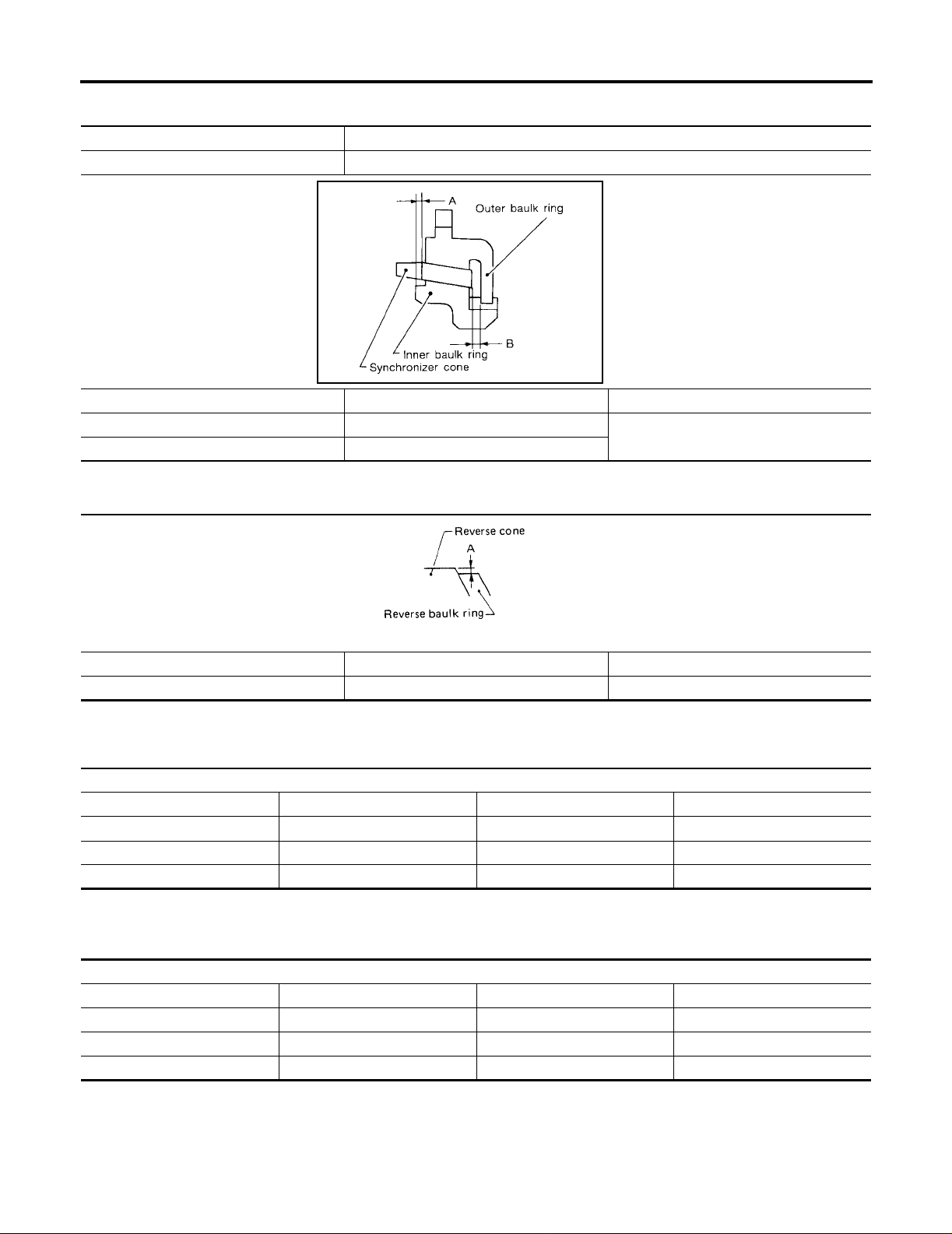
SERVICE DATA AND SPECIFICATIONS (SDS)
DOUBLE BAULK RING
VG33E model 2nd & 3rd baulk rings
VG33ER model 1st, 2nd & 3rd baulk rings
Dimension Standard Wear limit
A 0.7 - 0.9 (0.028 - 0.035)
B 0.6 - 1.1 (0.024 - 0.043)
[FS5R30A]
Unit: mm (in)
SMT742C
0.2 (0.008)
Distance Between Rear Surface of Reverse Cone and Reverse Baulk Ring
Unit: mm (in)
SMT428C
Dimension Standard Wear limit
A 0.3 5 to 0.95 (0 .0 119 to 0.0295) 1.1 (0.043)
Available Snap Ring
MAIN DRIVE GEAR SNAP RING
Unit: mm (in)
Main drive gear snap ring groove allowable cleara nce 0 - 0.1 (0 - 0.003)
Thickness Part number* Thickness Part num ber *
1.89 (0.0744) 32204-01G60 2.03 (0.0799) 32204-01G63
1.95 (0.0768) 32204-01G61 2.07 (0.0815) 32204-01G64
1.99 (0.0783) 32204-01G62 2.11 (0.0831) 32204-01G65
*Always check with the Parts Department for the latest parts information.
MAINSHAFT FRONT BEARING SNAP RING
Unit: mm (in)
Mainshaft front bearing snap ring groove allowable clearance 0 - 0.1 (0 - 0.003)
Thickness Part number* Thickness Part num ber *
1.99 (0.0783) 32204-01G62 2.11 (0.0831) 32204-01G65
2.03 (0.0799) 32204-01G63 2.15 (0.0846) 32204-01G66
2.07 (0.0815) 32204-01G64 2.19 (0.0862) 32204-01G67
*Always check with the Parts Department for the latest parts information.
ECS006J6
ECS006J7
MT-82

SERVICE DATA AND SPECIFICATIONS (SDS)
COUNTER GEAR REAR SNAP RING
Counter gear rear snap ring groove allowable clea ran ce 0 - 0.1 (0 - 0.003 )
Thickness Part number* Thickness Part number*
1.32 (0.0520) 32236-01G00 1.56 (0.0614) 32236-01G04
1.38 (0.0543) 32236-01G01 1.62 (0.0638) 32236-01G05
1.44 (0.0567) 32236-01G02 1.68 (0.0661) 32236-01G06
1.50 (0.0591) 32236-01G03 1.74 (0.0685) 32236-01G07
*Always check with the Parts Department for the late st parts information.
Available C-ring
MAINSHAFT C-RING
Mainshaft C-ring groove allowable cl ear ance 0 - 0.1 (0 - 0.003)
Thickness Part number* Thickness Part number*
2.63 (0.1035) 32348-01G15 3.19 (0.1256) 32348-01G07
2.70 (0.1063) 32348-01G00 3.26 (0.1283) 32348-01G08
2.77 (0.1091) 32348-01G01 3.33 (0.1311) 32348-01G09
2.84 (0.1118) 32348-01G02 3.40 (0.1339) 32348-01G10
2.91 (0.1146) 3 2348-01G03 3.47 (0.1366) 32348-01G11
2.98 (0.1173) 3 2348-01G04 3.54 (0.1394) 32348-01G12
3.05 (0.1201) 32348-01G05 3.61 (0.1421) 32348-01G13
3.12 (0.1228) 32348-01G06 3.68 (0.1449) 32348-01G14
*Always check with the Parts Department for the late st parts information.
[FS5R30A]
Unit: mm (in)
ECS006J8
Unit: mm (in)
A
B
MT
D
E
F
G
H
I
Available Shim and Washer
TABLE FOR SELECTING PROPER COUNTER GEAR FRONT BEARING SHIM
Counter gear end play 0.10 - 0.26 (0.0040 - 0.0102)
Dial indicator deflection Thickness of proper shim Part number*
0.93 - 1.02 (0.0367 - 0.0401) 0.80 (0.0 315) 32218-01G00
1.01 - 1.10 (0.0398 - 0.0433) 0.88 (0.0 346) 32218-01G11
1.09 - 1.18 (0.0430 - 0.0464) 0.96 (0.0 378) 32218-01G12
1.17 - 1.26 (0.0461 - 0.0496) 1.04 (0.0 409) 32218-01G13
1.25 - 1.34 (0.0493 - 0.0527) 1.12 (0.0 441) 32218-01G14
1.33 - 1.42 (0.0524 - 0.0559) 1.20 (0.0 472) 32218-01G04
1.41 - 1.50 (0.0556 - 0.0590) 1.28 (0.0 504) 32218-01G15
1.49 - 1.58 (0.0587 - 0.0622) 1.36 (0.0 535) 32218-01G16
1.57 - 1.66 (0.0619 - 0.0653) 1.44 (0.0 567) 32218-01G17
*Always check with the Parts Department for the late st parts information.
REVERSE IDLER REAR THRUST WASHER
Reverse idler gear end play 0.30 - 0.53 (0.0119 - 0.0208)
Thickness Part number*
A 1.97 (0.0776) 32284-01G10
B 2.07 (0.0815) 32284-01G11
*Always check with the Parts Department for the late st parts information.
ECS006J9
Unit: mm (in)
Unit: mm (in)
J
K
L
M
MT-83

SERVICE DATA AND SPECIFICATIONS (SDS)
[FS5R30A]
MT-84
 Loading...