

NIKON coolpix P1 REPAIR MANUAL
VAA39001-R.3673.A
作成承認印 配布許可印
VAA39001
REPAIR MANUAL
Printed in Japan September 2005
Copyright c 2005 by Nikon Corporation.
All Rights Reserved.
無断転載を禁ず
!!

VAA39001-R.3673.A
CONTENTS
SPECIFICATIONS ・・・・・・・・・・・・・・・・・・・・・・・・・・・・・・・・・・・・・・・・・・・・・・・・・・・・・・・・・・・・・・・・・・・・・・・・・ M1-M3
DISASSEMBLY
WARNING ・・・・・・・・・・・・・・・・・・・・・・・・・・・・・・・・・・・・・・・・・・・・・・・・・・・・・・・・・・・・・・・・・・・・・・・・・・・・・・・・・・D1
REMOVAL OF REAR COVER ・・・・・・・・・・・・・・・・・・・・・・・・・・・・・・・・・・・・・・・・・・・・・・・・・・・・・・・・・・・ D2-D3
REMOVAL OF ASSY CABI FRONT ・・・・・・・・・・・・・・・・・・・・・・・・・・・・・・・・・・・・・・・・・・・・・・・・・・・・・・・・・・・・・D3
REMOVAL OF DEC TOP ・・・・・・・・・・・・・・・・・・・・・・・・・・・・・・・・・・・・・・・・・・・・・・・・・・・・・・・・・・・・・・・・・・・・・・ D4
DISCHARGE OF MAIN CONDENSER ・・・・・・・・・・・・・・・・・・・・・・・・・・・・・・・・・・・・・・・・・・・・・・・・・・・・・・・・・・ D4
REMOVAL OF DEC Wi-Fi ・・・・・・・・・・・・・・・・・・・・・・・・・・・・・・・・・・・・・・・・・・・・・・・・・・・・・・・・・・・・・・・・・・・・・ D5
REMOVAL OF DEC RIGHT AND DEC LEFT ・・・・・・・・・・・・・・・・・・・・・・・・・・・・・・・・・・・・・・・・・・・・・・・・・・・・・D5
REMOVAL OF LCD ・・・・・・・・・・・・・・・・・・・・・・・・・・・・・・・・・・・・・・・・・・・・・・・・・・・・・・・・・・・・・・・・・・・・・・・・・・D6
REMOVAL OF COMPL PWBDM-1 ・・・・・・・・・・・・・・・・・・・・・・・・・・・・・・・・・・・・・・・・・・・・・・・・・・・・・・・D7-D8
MAC ADDRESS ・・・・・・・・・・・・・・・・・・・・・・・・・・・・・・・・・・・・・・・・・・・・・・・・・・・・・・・・・・・・・・・・・・・・・・・・・・・・・D8
REMOVAL OF HOLDER STRAP ・・・・・・・・・・・・・・・・・・・・・・・・・・・・・・・・・・・・・・・・・・・・・・・・・・・・・・・・・・・・・・・ D9
REMOVAL OF UNIT SLD ・・・・・・・・・・・・・・・・・・・・・・・・・・・・・・・・・・・・・・・・・・・・・・・・・・・・・・・・・・・・・・・・・・・・・ D9
REMOVAL OF MICROPHONE ・・・・・・・・・・・・・・・・・・・・・・・・・・・・・・・・・・・・・・・・・・・・・・・・・・・・・・・・・・・・・・・D10
REMOVAL OF HOLDER MONITOR ・・・・・・・・・・・・・・・・・・・・・・・・・・・・・・・・・・・・・・・・・・・・・・・・・・・・・・・・・・D11
REMOVAL OF HOLDER UNIT TOP ・・・・・・・・・・・・・・・・・・・・・・・・・・・・・・・・・・・・・・・・・・・・・・・・・・・・・・・・・・・D12
REMOVAL OF HOLDER SPEAKER ・・・・・・・・・・・・・・・・・・・・・・・・・・・・・・・・・・・・・・・・・・・・・・・・・・・・・・・・・・D12
REMOVAL OF SPERKER ・・・・・・・・・・・・・・・・・・・・・・・・・・・・・・・・・・・・・・・・・・・・・・・・・・・・・・・・・・・・・・・・・・・ D13
REMOVAL OF COMPL PWBTB-1 ・・・・・・・・・・・・・・・・・・・・・・・・・・・・・・・・・・・・・・・・・・・・・・・・・・・・・・・・・・・・D13
DISASSEMBLY OF COMPL PWBTB-1 ・・・・・・・・・・・・・・・・・・・・・・・・・・・・・・・・・・・・・・・・・・・・・・・・・・・・・・・・D14
REMOVAL OF CONDENSER ・・・・・・・・・・・・・・・・・・・・・・・・・・・・・・・・・・・・・・・・・・・・・・・・・・・・・・・・・・・・・・・・D14
REMOVAL OF BATTERY COVER ・・・・・・・・・・・・・・・・・・・・・・・・・・・・・・・・・・・・・・・・・・・・・・・・・・・・・・・・・・・・ D15
DISASSEMBLY OF BATTERY COVER ・・・・・・・・・・・・・・・・・・・・・・・・・・・・・・・・・・・・・・・・・・・・・・・・ D16-D17
REMOVAL OF HOLDER FLASH ・・・・・・・・・・・・・・・・・・・・・・・・・・・・・・・・・・・・・・・・・・・・・・・・・・・・・・・・・・・・・D18
REMOVAL OF COMPL PWBCP-1 ・・・・・・・・・・・・・・・・・・・・・・・・・・・・・・・・・・・・・・・・・・・・・・・・・・・・・・・・・・・・ D19
REMOVAL OF LENS UNIT ・・・・・・・・・・・・・・・・・・・・・・・・・・・・・・・・・・・・・・・・・・・・・・・・・・・・・・・・・・・・・・・・・・ D20
POINTS TO NOTICE WHEN DISASSEMBLING / ASSEMBLING LENS UNIT ・・・・・・・・・・・・・・・・・・・・・・・ D21
TOOLS REQUIRED FOR FFD INSPECTION AND ADJUSTMENT ・・・・・・・・・・・・・・・・・・・・・・・・・・・・・・・・・ D21
REMOVAL OF LENS BARREL UNIT ・・・・・・・・・・・・・・・・・・・・・・・・・・・・・・・・・・・・・・・・・・・・・・・・・・・・・・・・・D22
REMOVAL OF KNURLED GEAR ・・・・・・・・・・・・・・・・・・・・・・・・・・・・・・・・・・・・・・・・・・・・・・・・・・・・・・・・・・・・D23
REMOVAL OF BARRIER UNIT ・・・・・・・・・・・・・・・・・・・・・・・・・・・・・・・・・・・・・・・・・・・・・・・・・・・・・・・・・・・・・・D23
REMOVAL OF BARRIER RELEASE RING ・・・・・・・・・・・・・・・・・・・・・・・・・・・・・・・・・・・・・・・・・・・・・・・・・・・・・ D24
REMOVAL OF 1ST LENS GROUP UNIT ・・・・・・・・・・・・・・・・・・・・・・・・・・・・・・・・・・・・・・・・・・・・・・・・・・・・・・・D24
REMOVAL OF FIXED BARREL ・・・・・・・・・・・・・・・・・・・・・・・・・・・・・・・・・・・・・・・・・・・・・・・・・・・・・・・・・・・・・・ D25
REMOVAL OF CAM BARREL ・・・・・・・・・・・・・・・・・・・・・・・・・・・・・・・・・・・・・・・・・・・・・・・・・・・・・・・・・・・・・・・D25
REMOVAL OF STRAIGHT BARREL ・・・・・・・・・・・・・・・・・・・・・・・・・・・・・・・・・・・・・・・・・・・・・・・・・・・・・・・・・・ D26
REMOVAL OF 2ND LENS GROUP UNIT ・・・・・・・・・・・・・・・・・・・・・・・・・・・・・・・・・・・・・・・・・・・・・・・・・・・・・・D26
- P1 -

VAA39001-R.3673.A
REMOVAL OF SHUTTER UNIT ・・・・・・・・・・・・・・・・・・・・・・・・・・・・・・・・・・・・・・・・・・・・・・・・・・・・・・・・・・・・・・ D27
REMOVAL OF ZOOM MOTOR UNIT ・・・・・・・・・・・・・・・・・・・・・・・・・・・・・・・・・・・・・・・・・・・・・・・・・・・・・・・・・ D28
ASSEMBLY
INSTALLATION OF ZOOM MOTOR UNIT ・・・・・・・・・・・・・・・・・・・・・・・・・・・・・・・・・・・・・・・・・・・・・・・・・・・・・・・ A1
INSTALLATION OF SHUTTER UNIT ・・・・・・・・・・・・・・・・・・・・・・・・・・・・・・・・・・・・・・・・・・・・・・・・・・・・・・・・・・・A2
INSTALLATION OF 2ND LENS GROUP UNIT ・・・・・・・・・・・・・・・・・・・・・・・・・・・・・・・・・・・・・・・・・・・・・・・・・・・・ A2
INSTALATION OF STRAIGHT BARREL ・・・・・・・・・・・・・・・・・・・・・・・・・・・・・・・・・・・・・・・・・・・・・・・・・・・・・・・・A3
INSTALLATION OF CAM BARREL ・・・・・・・・・・・・・・・・・・・・・・・・・・・・・・・・・・・・・・・・・・・・・・・・・・・・・・・・・・・・A4
INSTALLATION OF FIXED BARREL ・・・・・・・・・・・・・・・・・・・・・・・・・・・・・・・・・・・・・・・・・・・・・・・・・・・・・A5-A6
INSTALLATION OF FIRST LENS GROUP UNIT ・・・・・・・・・・・・・・・・・・・・・・・・・・・・・・・・・・・・・・・・・・・・・・・・・・A7
INSTALLATION OF BARRIER RELEASE RING ・・・・・・・・・・・・・・・・・・・・・・・・・・・・・・・・・・・・・・・・・・・・・・・・・・ A7
INSTALLATION OF BARRIER UNIT ・・・・・・・・・・・・・・・・・・・・・・・・・・・・・・・・・・・・・・・・・・・・・・・・・・・・・・・・・・・A8
INSTALLATION OF KNURED GEAR ・・・・・・・・・・・・・・・・・・・・・・・・・・・・・・・・・・・・・・・・・・・・・・・・・・・・・・・・・・・A9
INSTALLATION OF LENS BARREL UNIT ・・・・・・・・・・・・・・・・・・・・・・・・・・・・・・・・・・・・・・・・・・・・・・・・・・・・・A10
FFD INSPECTION AND ADJUSTMENT ・・・・・・・・・・・・・・・・・・・・・・・・・・・・・・・・・・・・・・・・・・・・・・・ A11-A13
OPERATION/RESOLUTION INSPECTION ・・・・・・・・・・・・・・・・・・・・・・・・・・・・・・・・・・・・・・・・・・・・・・・・・・・・・A14
INSTALLATION OF LENS UNIT ・・・・・・・・・・・・・・・・・・・・・・・・・・・・・・・・・・・・・・・・・・・・・・・・・・・・・・・・・・・・・A15
INSTALLATION OF COMPL PWBCP-1 ・・・・・・・・・・・・・・・・・・・・・・・・・・・・・・・・・・・・・・・・・・・・・・・・・・・・・・・・A16
INSTALLATION OF HOLDER FLASH ・・・・・・・・・・・・・・・・・・・・・・・・・・・・・・・・・・・・・・・・・・・・・・・・・・・・・・・・A17
ASSEMBLY OF BATTERY COVER ・・・・・・・・・・・・・・・・・・・・・・・・・・・・・・・・・・・・・・・・・・・・・・・・・・・A18-A20
INSTALLATION OF BATTERY COVER ・・・・・・・・・・・・・・・・・・・・・・・・・・・・・・・・・・・・・・・・・・・・・・・A21-A22
INSTALLATION OF CONDENSER ・・・・・・・・・・・・・・・・・・・・・・・・・・・・・・・・・・・・・・・・・・・・・・・・・・・・・・・・・・・A22
ASSEMBLY OF COMPL PWBTB-1 ・・・・・・・・・・・・・・・・・・・・・・・・・・・・・・・・・・・・・・・・・・・・・・・・・・・・・・・・・・・A23
INSTALLATION OF COMPL PWBTB-1 ・・・・・・・・・・・・・・・・・・・・・・・・・・・・・・・・・・・・・・・・・・・・・・・・・・・・・・・A23
INSTALLATION OF SPEAKER ・・・・・・・・・・・・・・・・・・・・・・・・・・・・・・・・・・・・・・・・・・・・・・・・・・・・・・・・・・・・・・ A24
INSTALLATION OF HOLDER SPEAKER ・・・・・・・・・・・・・・・・・・・・・・・・・・・・・・・・・・・・・・・・・・・・・・・・・・・・・・A25
INSTALLATION OF HOLDER UNIT TOP ・・・・・・・・・・・・・・・・・・・・・・・・・・・・・・・・・・・・・・・・・・・・・・・・・・・・・・A26
INSTALLATION OF HOLDER MONITOR ・・・・・・・・・・・・・・・・・・・・・・・・・・・・・・・・・・・・・・・・・・・・・・・・・・・・・A27
INSTALLATION OF MICROPHONE ・・・・・・・・・・・・・・・・・・・・・・・・・・・・・・・・・・・・・・・・・・・・・・・・・・・・・・・・・・ A28
INSTALLATION OF UNIT SLD ・・・・・・・・・・・・・・・・・・・・・・・・・・・・・・・・・・・・・・・・・・・・・・・・・・・・・・・・・・・・・・A29
INSTALLATION OF HOLDER STRAP ・・・・・・・・・・・・・・・・・・・・・・・・・・・・・・・・・・・・・・・・・・・・・・・・・・・・・・・・・A29
INSTALLATION OF COMPL PWBDM-1 ・・・・・・・・・・・・・・・・・・・・・・・・・・・・・・・・・・・・・・・・・・・・・・・ A30-A31
INSTALLATION OF LCD ・・・・・・・・・・・・・・・・・・・・・・・・・・・・・・・・・・・・・・・・・・・・・・・・・・・・・・・・・・・・・・・・・・・A32
INSTALLATION OF DEC RIGHT AND DEC LEFT ・・・・・・・・・・・・・・・・・・・・・・・・・・・・・・・・・・・・・・・・・・・・・・ A32
INSTALLATION OF DEC Wi-Fi ・・・・・・・・・・・・・・・・・・・・・・・・・・・・・・・・・・・・・・・・・・・・・・・・・・・・・・・・・・・・・・A33
INSTALLATION OF DEC TOP ・・・・・・・・・・・・・・・・・・・・・・・・・・・・・・・・・・・・・・・・・・・・・・・・・・・・・・・・・・・・・・・A33
INSTALLATION OF ASSY CABI FRONT ・・・・・・・・・・・・・・・・・・・・・・・・・・・・・・・・・・・・・・・・・・・・・・・・・・・・・・ A34
INSTALLATION OF CABINET BACK ・・・・・・・・・・・・・・・・・・・・・・・・・・・・・・・・・・・・・・・・・・・・・・・・・ A34-A35
- P1 -

VAA39001-R.3673.A
ADJUSTMENT ・・・・・・・・・・・・・・・・・・・・・・・・・・・・・・・・・・・・・・・・・・・・・・・・・・・・・・・・・・・・・・・・・・・・・・・A36-A45
DISCRIPTION OF CIRCUIT ・・・・・・・・・・・・・・・・・・・・・・・・・・・・・・・・・・・・・・・・・・・・・・・・・・・・・・・・・・・・・・・・・ E1-E8
ELECTRICITY
OVERALL WIRING ・・・・・・・・・・・・・・・・・・・・・・・・・・・・・・・・・・・・・・・・・・・・・・・・・・・・・・・・・・・・・・・・・・・・・・・・・・ E9
CP1 (DMA) CIRCUIT DIAGRAM ・・・・・・・・・・・・・・・・・・・・・・・・・・・・・・・・・・・・・・・・・・・・・・・・・・・・・・・・・・・・・E10
CP1 (CAA) CIRCUIT DIAGRAM ・・・・・・・・・・・・・・・・・・・・・・・・・・・・・・・・・・・・・・・・・・・・・・・・・・・・・・・・・・・・・ E11
CP1 (STA) CIRCUIT DIAGRAM ・・・・・・・・・・・・・・・・・・・・・・・・・・・・・・・・・・・・・・・・・・・・・・・・・・・・・・・・・・・・・・ E12
CP1 (SYA) CIRCUIT DIAGRAM ・・・・・・・・・・・・・・・・・・・・・・・・・・・・・・・・・・・・・・・・・・・・・・・・・・・・・・・・・・・・・・ E13
CP1 (PWA), TB2 CIRCUIT DIAGRAM ・・・・・・・・・・・・・・・・・・・・・・・・・・・・・・・・・・・・・・・・・・・・・・・・・・・・・・・・・ E14
CA-1 CIRCUIT DIAGRAM ・・・・・・・・・・・・・・・・・・・・・・・・・・・・・・・・・・・・・・・・・・・・・・・・・・・・・・・・・・・・・・・・・・ E15
DM-1 CIRCUIT DIAGRAM ・・・・・・・・・・・・・・・・・・・・・・・・・・・・・・・・・・・・・・・・・・・・・・・・・・・・・・・・・・・・・・・・・・ E16
OVERALL BLOCK DIAGRAM ・・・・・・・・・・・・・・・・・・・・・・・・・・・・・・・・・・・・・・・・・・・・・・・・・・・・・・・・・・・・・・・E17
CCD BLOCK DIAGRAM ・・・・・・・・・・・・・・・・・・・・・・・・・・・・・・・・・・・・・・・・・・・・・・・・・・・・・・・・・・・・・・・・・・・・ E18
LENS BLOCK DIAGRAM ・・・・・・・・・・・・・・・・・・・・・・・・・・・・・・・・・・・・・・・・・・・・・・・・・・・・・・・・・・・・・・・・・・・E19
ASIC BLOCK DIAGRAM ・・・・・・・・・・・・・・・・・・・・・・・・・・・・・・・・・・・・・・・・・・・・・・・・・・・・・・・・・・・・・・・・・・・ E20
SYSTEM CONTROL BLOCK DIAGRAM ・・・・・・・・・・・・・・・・・・・・・・・・・・・・・・・・・・・・・・・・・・・・・・・・・・・・・・E21
POWER BLOCK DIAGRAM ・・・・・・・・・・・・・・・・・・・・・・・・・・・・・・・・・・・・・・・・・・・・・・・・・・・・・・・・・・・・・・・・・E22
FUSE ARRENGEMENT (CP1 PCB) ・・・・・・・・・・・・・・・・・・・・・・・・・・・・・・・・・・・・・・・・・・・・・・・・・・・・・・・・・・・ E23
INSPECTION STANDARDS ・・・・・・・・・・・・・・・・・・・・・・・・・・・・・・・・・・・・・・・・・・・・・・・・・・・・・・・・・・・・・・ R1-R10
TOOL LIST ・・・・・・・・・・・・・・・・・・・・・・・・・・・・・・・・・・・・・・・・・・・・・・・・・・・・・・・・・・・・・・・・・・・・・・・・・・・・・・・ T1-T5
- P1 -

SPECIFICATIONS
Type COOLPIX P1 digital camera
Effective pixels 8.0 million
CCD
1/1.8 in. high-density CCD; total pixels: 8.31 million
VAA39001-R.3673.A
Image size (pixels)
Lens
Focal length
f/-number
Constr uction
Digital zoom Up to 4 × (35-mm [135] camera-format equivalent: 504 mm)
Autofocus (AF)
Focus range
Focus area selection
AF-assist illuminator
Monitor
・3,264 × 2,448 [8M] ・2,592 × 1,944 [5M] ・2,048 × 1,536 [3M]
・1,600 × 1,200 [2M] ・1,280 × 960 [1M] ・1,024 × 768 [PC]
・640 × 480 [TV] ・3,264 × 2,176 [3:2]
3.5 × Zoom-Nikkor ED lens
F=7.5 - 26.3 mm
(35-mm [135] camera-format equivalent: 36 - 126 mm)
f/2.7 - f/5.2
Seven elements in six groups
Contrast-detect through-the-lens (TTL) AF, AF-assist illuminator
50 cm/1 ft. 8 in. - ∞ ; macro mode 4 cm/1.6 in. (W) - ∞
Auto (nine-area automatic selection), Manual (99-area manual selection), Center (center
focus area selection)
CLASS 1 LED PRODUCT (IEC60825-1 Edition 1.2
Maximum output: 1900 μ W
2.5 in., 110,000-dot, amorphous silicon TFT transflective LCD with brightness
adjustment
-2001
)
Frame coverage
(shooting mode)
Storage
Media
File system
File formats
Exposure
Metering
Exposure control
Range
Shutter
Approximately 100% horizontal and 97% vertical
Internal memory (approximately 32 MB) / SD (Secure Digital) Memory cards
Compliant with Design Rule for Camera File System (DCF), Exif 2.2, and Digital Print
Order Format (DPOF)
Compressed: JPEG-baseline-compliant (1:4, 1:8, 1:16)
Movies: QuickTime Sound files: WAV
Four mode through-the-lens (TTL) metering;
・256-segment matrix ・Spot ・Center-weighted ・Spot AF area
Programmed auto, Aperture-priority auto, Exposure compensation (-2.0 - +2.0 EV in
steps of 1/3 EV), Auto bracketing
W: -1.0 - +19.0 EV
T: +0.5 - +19.0 EV
(Sensitivity: Auto)
Mechanical and charge-coupled electronic shutter
Speed
Aperture
Range
8 - 1/2,000 s
Three-blade hexagonal iris diaphragm
10 (in steps of 1/3 EV)
- M1 ・ P1 -
VAA39001-R.3673.A
ISO Sensitivity
( R ec om m e n d e d Ex p o s u r e
Approximately equivalent to ISO 50, 100, 200, 400; Auto (auto gain to ISO 200
equivalent)
Index)
Self-timer Ten-second, three-second duration
Built-in Flash
Range (approx.)
W: 0.5 - 3.8 m/1 ft. 8 in. - 12 ft. 6 in.
T: 0.5 - 2.0 m/1 ft. 8 in. - 6 ft. 7 in.
(Sensitivity: Auto)
Flash control
Sensor flash system
Interface Hi-Speed USB 2.0, IEEE802.11/b11g
Video output Can be selected from NTSC and PAL
I/O terminals DC in; Digital I/O (audio-visual out and USB)
Supported language Chinese (Simplified and Traditional), Dutch, English, French, German, Italian, Japanese,
Korean, Russian, Spanish, Swedish
Power sources ・One rechargeable Nikon EN-EL8 rechargeable lithium-ion battery (supplied)
・EH-62C AC adapter kit (available separately)
Approximate battery life Approximately 180 shots
Based on CIPA standard
*1
Dimensions (W × H × D) Approximately 91 × 60 × 39 mm/3.6 in. × 2.4 in. × 1.5 in.
(excluding projection parts)
Approximate weight 170 g (6.0 oz) without battery or memory card
Operating environment
Temperature
Humidity
0 - 40° C (32 - 104° F)
Less than 85% (no condensation)
*1 Industry standard for measuring life of camera batteries. Measured at 25° C (77° F); zoom adjusted with each shot,
built-in flash fired with every other shot, image mode set to NORM/ .
・ Design Rule for Camera File System (DCF)
Your camera conforms to the Design Rule for Camera File System (DCF), a standard widely used in the digital camera
industry to ensure compatibility among different makes of camera.
・ Exif Version 2.2
Your camera supports Exif (Exchangeable Image File Format for Digital Still Cameras) version 2.2, a standard that allows
information stored with pictures to be used for optimal color reproduction when images are output on Exif-compliant
printers.
- M2・ P1 -

Wireless transfer unit
Standard to comply with IEEE802.11b/g (Wireless LAN standard protocol)
ARIB STD-T66 (small electricity data communication system standard)
Transmission method IEEE802.11g: OFDM
IEEE802.11b: DBPSK, DQPSK, CCK
VAA39001-R.3673.A
Communication distance
(estimated)
Frequency range in
Approx. 30m
※ The communication distance is influenced by shades, weather, etc.
2412 ~ 2462 MHz (11 channels)
specifications
(Center frequency)
Data transfer speed
(Standard value
※ 1
)
IEEE802.11g : 54M/48M/36M/24M/18M/12M/9M/6M(bps)
IEEE802.11b : 11M/5.5M/2M/1M(bps)
Security 128/64 bit WEP、TKIP
Access method Infrastructure mode/Ad hoc mode
・ The data in specifications are those when the accessory rechargeable battery EN-EL8 is used under the full-charged
condition in the normal temperature (25℃ ).
※ 1: The indicated values are the theoretical maximum values according to the wireless LAN standard. They do not show
the actual data transfer speed.
- M3 ・ P1 -
Disassembly
WARNING
There are high voltege parts inside. Be careful of this electric shock,
when you remove the cover.
Yo
u must discharge the main condenser according to the instruction
of this repair manual after you remove the cover
.
!
・ Lead-free solder is used for this product.
・ For soldering work, the special solder and soldering iron are required.
・ Do NOT mix up lead-free solder with traditional solder.
・ Use the special soldering iron respectively for lead-free solder and lead solder. They cannot
be used in common.
VAA39001-R.3673.A
Points to notice for Lead-free solder products
Note : ① Be sure to remove the SD memory card and batteries before disassembly.
② When disassembling, make sure to memorize the processing state of wires, screws to be
fixed and their types, etc.
③ Because electrical parts are easily damaged by static electricity, make sure that you are
well earthed/grounded.
※ Caution for repairing wireless parts
When you replace the wireless LAN PCB (DM-1 PCB), it is necessary to record and
manage the changed data.
• MAC address
• PCB production lot number
• Camera body serial number
- D1 ・ P1 -
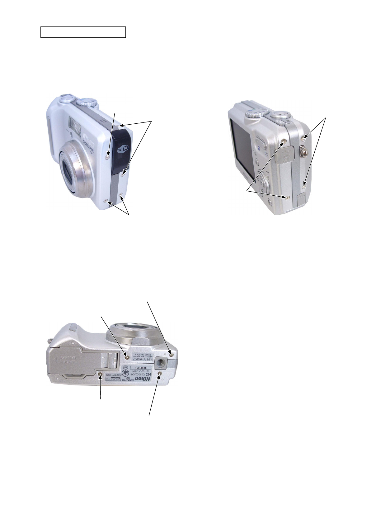
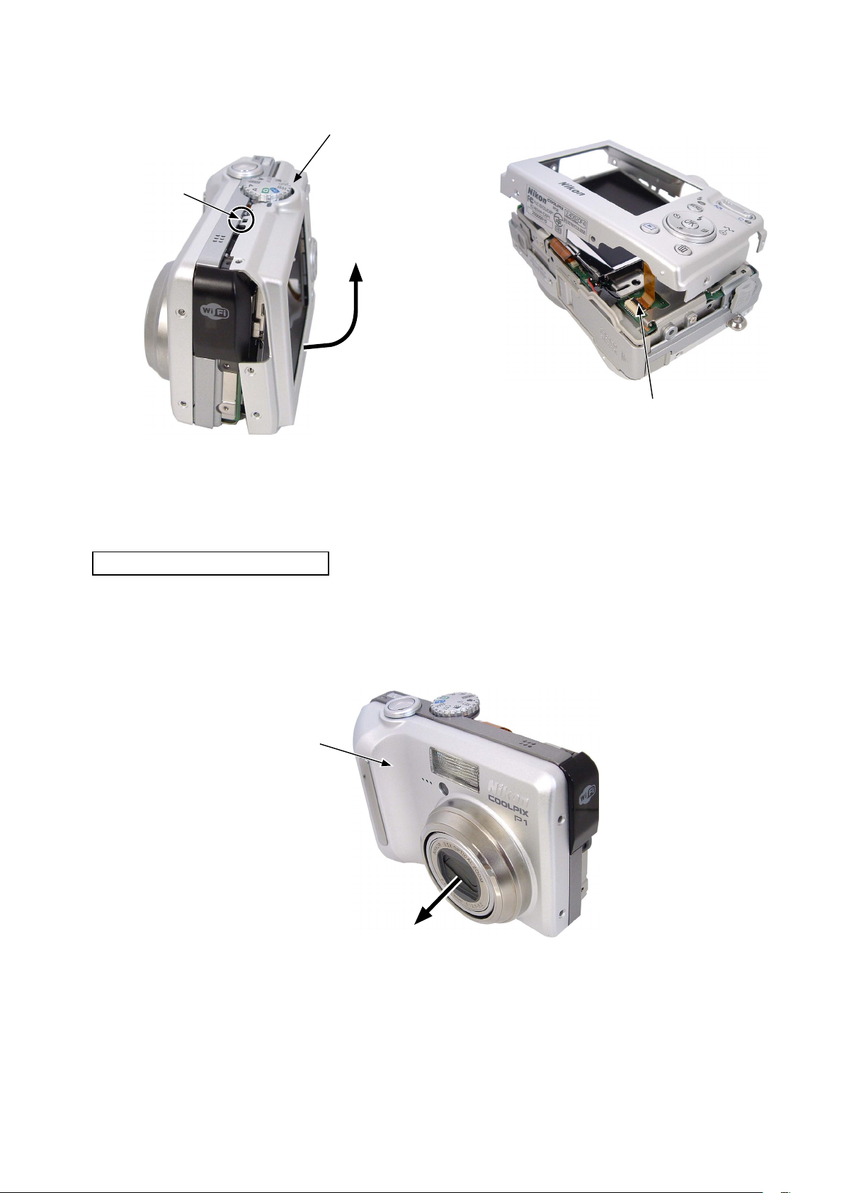
REMOVAL OF REAR COVER
※ The driver bit (J63076) is necessary for the screw [#1207].
VAA39001-R.3673.A
・ Remove the two screws [#1207].
・ Remove the three screws [#1201].
Screw [#1201]
Screw [#1201]
・ Remove the two screws A [#1203].
・ Remove the two screws B [#1203].
Screw B [#1203]
Screw [#1207]
Screw A [#1203]
・ Remove the screw C [#1201].
・ Remove the screw D [#1201].
・ Remove the screw E [#1202].
・ Remove the screw F [#1202].
Screw D [#1201]
Screw C [#1201]
Screw F [#1202]
Screw E [#1202]
- D2 ・ P1 -
VAA39001-R.3673.A
・ Open the bottom of the CABINET BACK [#1024] and perform unhooking. Lift up the rear cover and remove the FPC.
CABINET BACK [#1024]
Hook
Open the bottom.
FPC
REMOVAL OF ASSY CABI FRONT
・ Remove the ASSY CABI FRONT [#1003].
ASSY CABI FRONT [#1003]
- D3 ・ P1 -

WARNING
There are high voltege parts inside. Be careful of this electric shock,
when you remove the cover.
Yo
u must discharge the main condenser according to the instruction
of this repair manual after you remove the cover
.
!
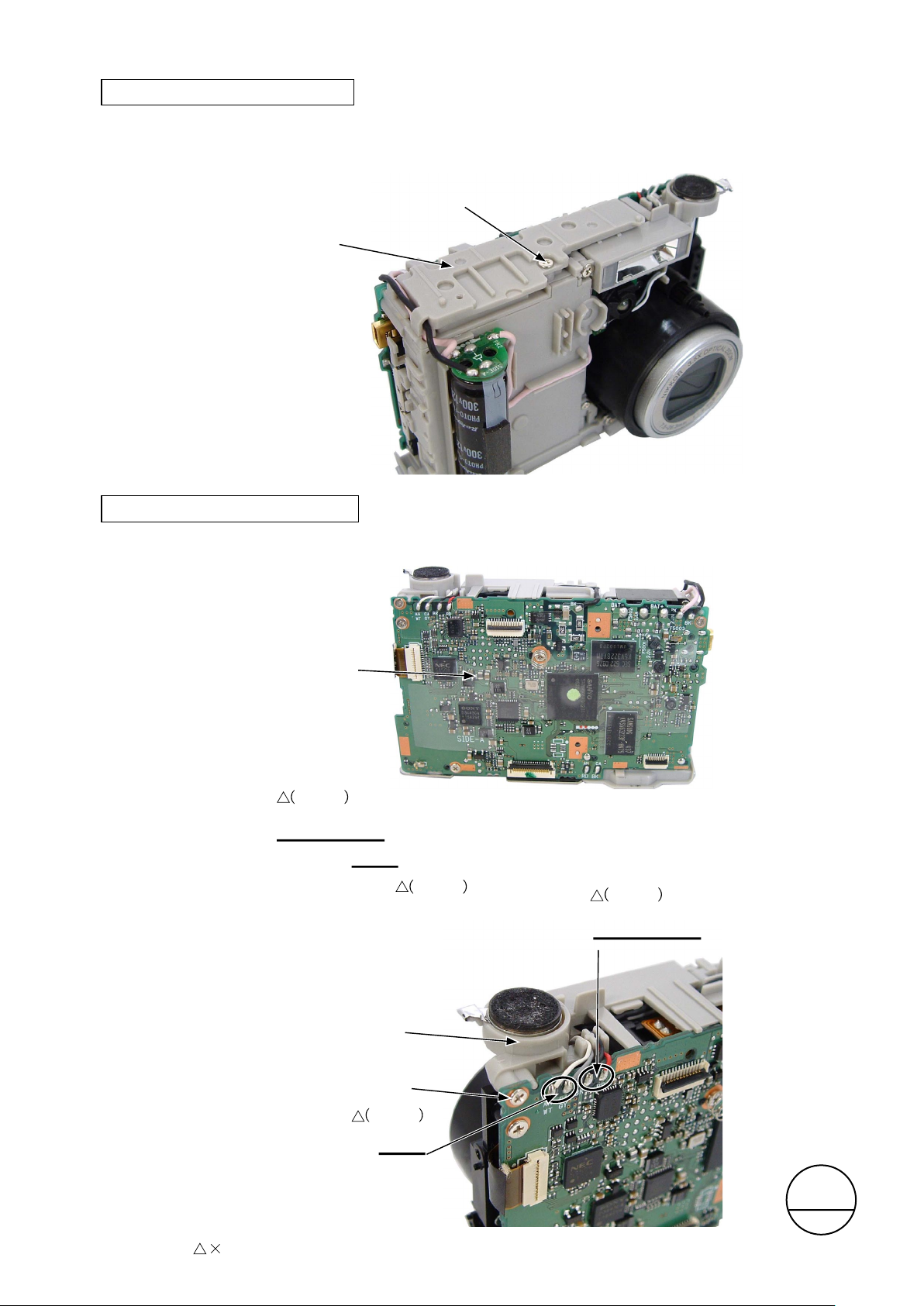
REMOVAL OF DEC TOP
・ Perform unhooking and remove the DEC TOP [#1020].
DEC TOP [#1020]
Hook
VAA39001-R.3673.A
DISCHARGE OF MAIN CONDENSER
2K Ω /5W
- D4 ・ P1 -
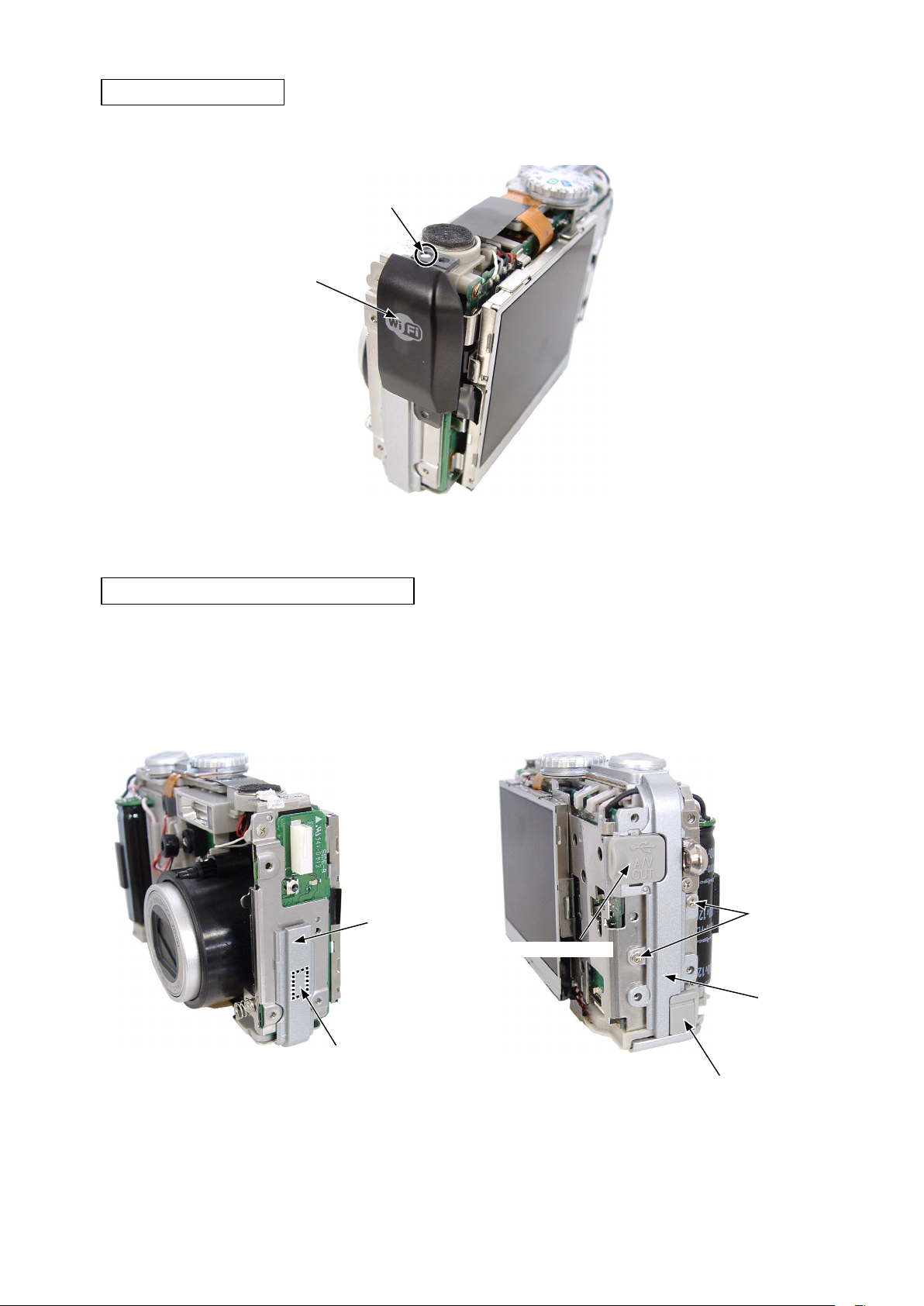
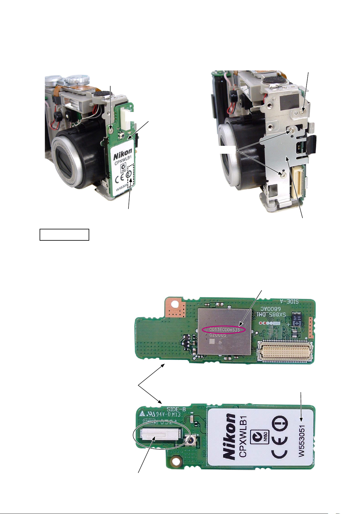
REMOVAL OF DEC Wi-Fi
・ Remove the DEC Wi-Fi [#1010] from the boss.
Boss
DEC Wi-Fi [#1010]
VAA39001-R.3673.A
REMOVAL OF DEC RIGHT AND DEC LEFT
・ Take off the DEC RIGHT [#1008].
(It is adhered by the double sided adhesive tape.)
DEC RIGHT [#1008]
・ Remove the two screws [#1205].
・ The DEC LEFT [#1014] and the cover USB [#1013] can
be removed.
・ Remove the cover DC [#1012].
Screw [#1205]
Cover USB [#1013]
DEC LEFT [#1014]
The double sided adhesive tape is
applied on the rear side.
Cover DC [#1012]
- D5 ・ P1 -
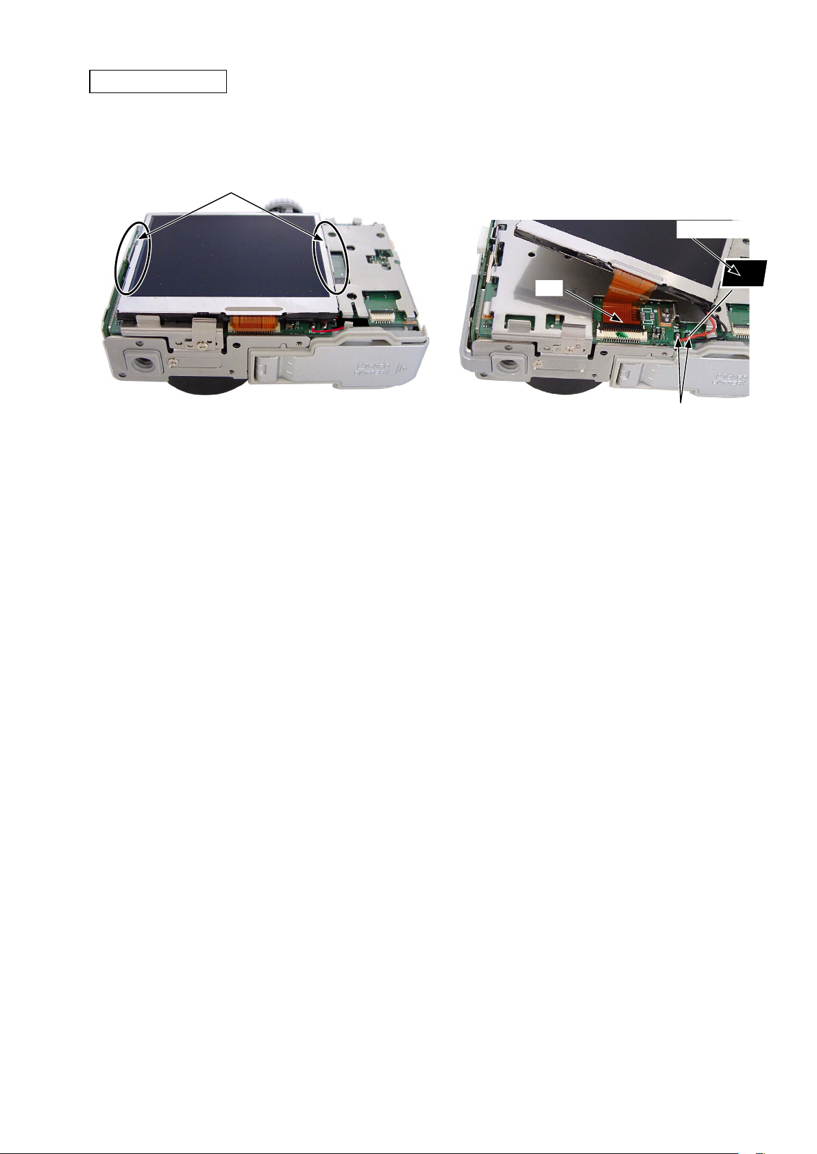
REMOVAL OF LCD
・ Remove the right hook and then remove the left hook.
Hook
VAA39001-R.3673.A
・ Take off the spacer [#1029].
・ Unsolder the lead wires [red] and [black].
・ Remove the FPC.
Spacer [#1029]
FPC
Lead wires [red] and [black]
- D6 ・ P1 -
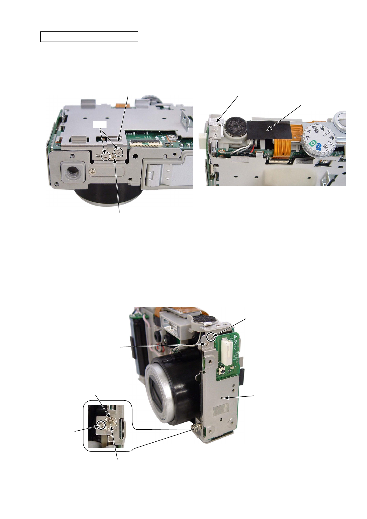
REMOVAL OF COMPL PWBDM-1
VAA39001-R.3673.A
・ Remove the screw [#1212].
・ Remove the spring LCD [#1149] from the bosses (2
places).
Spring LCD [#1149]
Boss
Screw [#1212]
・ Take off the shield tape SP holder 2 [#1011].
・ Take off the spacer [#1019].
Shield tape SP holder 2 [#1011]
Spacer [#1019]
・ Remove the screw [#1205].
・ The spring earth zoom [#1131] can be removed.
・ Remove the screw [#1212].
・ Remove the HOLDER DEC RIGHT [#1132] from the bosses (2 places).
Screw [#1212]
Spring earth zoom [#1131]
Boss
Boss
HOLDER DEC RIGHT [#1132]
Screw [#1205]
- D7 ・ P1 -
VAA39001-R.3673.A
・ Remove the screw [#1212].
・ Remo ve the COM PL PWBDM-1 [#1130] fr om the
connector.
Screw [#1212]
COMPL PWBDM-1 [#1130]
・ Remove the screw [#1212].
・ Remove the two screws [#1210].
・ Remove the holder plate Wi-Fi [#1127].
Screw [#1212]
Screw [#1210]
There is the connector on the rear side.
Holder plate Wi-Fi [#1127]
MAC ADDRESS
・ When you remove and replace the COMPL PWBDM-1 [#1130], record the MAC address, the production lot number
and the camera body serial number after the replacement.
・ Be careful not to touch the antenna electrode. (If you touch it, the characteristics of antenna may be influenced.)
MAC address
COMPL PWBDM-1 [#1130]
Production lot number
Antenna electrode
- D8 ・ P1 -
REMOVAL OF HOLDER STRAP
・ Remove the screw [#1205].
・ Remove the holder strap [#1015].
Holder strap [#1015]
Screw [#1205]
REMOVAL OF UNIT SLD
VAA39001-R.3673.A
・ Remove the FPC.
FPC
・ Remove the screw [#1206].
・ Remove the unit SLD [#1018].
・ The holder earth top [#1116] can be removed.
Unit SLD [#1018]
・ Remove the spacer [#1025].
Spacer [#1025]
Screw [#1206]
Holder earth top [#1116]
- D9 ・ P1 -
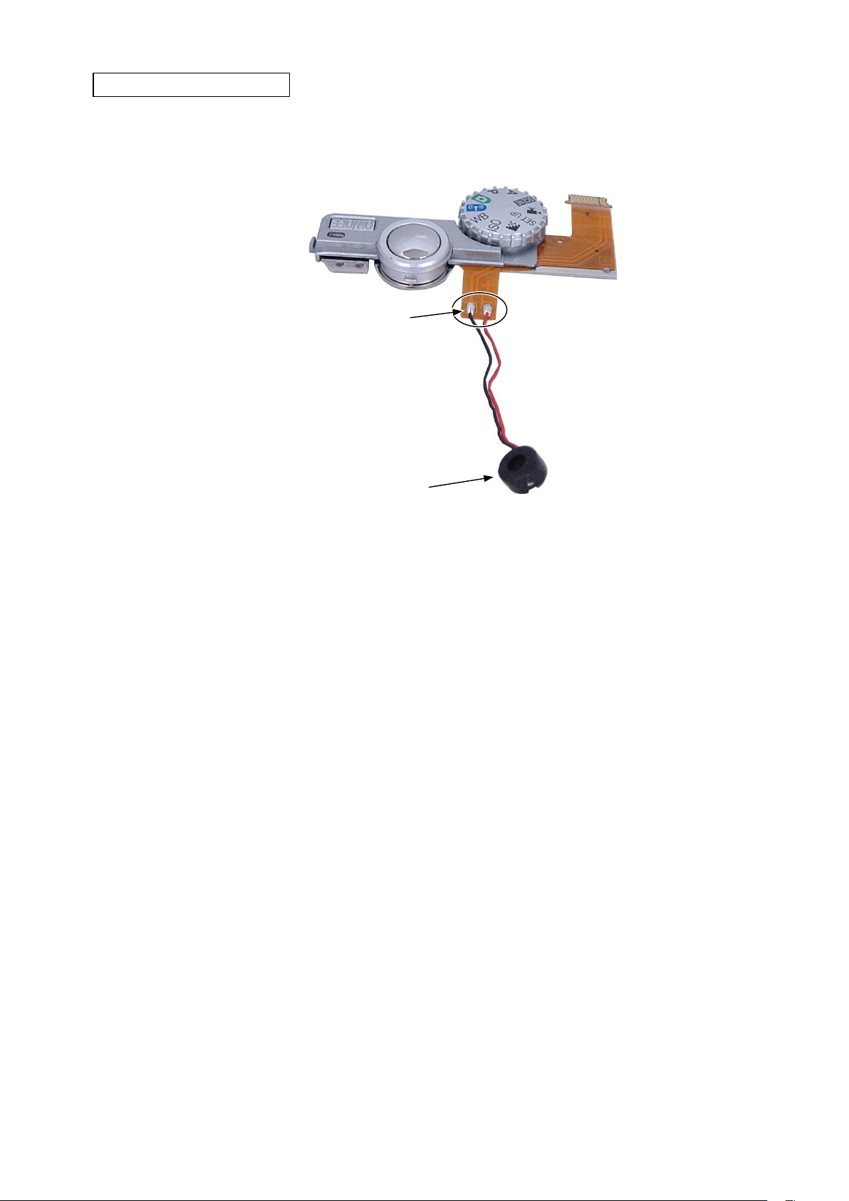
REMOVAL OF MICROPHONE
・ Unsolder the lead wires [black] and [red].
・ The microphone [#1017] can be removed.
Lead wires [black] and [red]
VAA39001-R.3673.A
Microphone [#1017]
- D10 ・ P1 -
REMOVAL OF HOLDER MONITOR
・ Remove the two screws [#1204].
・ Remove the two screws [#1210].
VAA39001-R.3673.A
Screw [#1204]
・ Remove the holder monitor [#1150] from the boss of the bottom and then remove the right boss.
・ The holder monitor [#1150] can be removed.
Screw [#1210]
Holder monitor [#1150]
Boss
Boss
Screw [#1210]
- D11 ・ P1 -
REMOVAL OF HOLDER UNIT TOP
・ Remove the screw [#1210].
・ Remove the holder unit top [#1119].
Holder unit top [#1119]
VAA39001-R.3673.A
Screw [#1210]
REMOVAL OF HOLDER SPEAKER
・ Take off the spacer CP1 [#1148].
Spacer CP1 [#1148]
Revise
[black] and [red]
・ Unsolder the lead wires [red] and [black].
・ Unsolder the lead wires [white] and [black].
・ Remove the screw [#1204].
・ Remove the holder speaker [#1137].
[gray]
Revise
Revise
[black]
Lead wires [red] and [black]
and [red]
Revise page
Holder speaker [#1137]
Screw [#1204]
Revise
[gray]
Lead wires [white] and [black]
4
- D12 ・ P1 -
サービス
計画課
M
Oct.5.2005
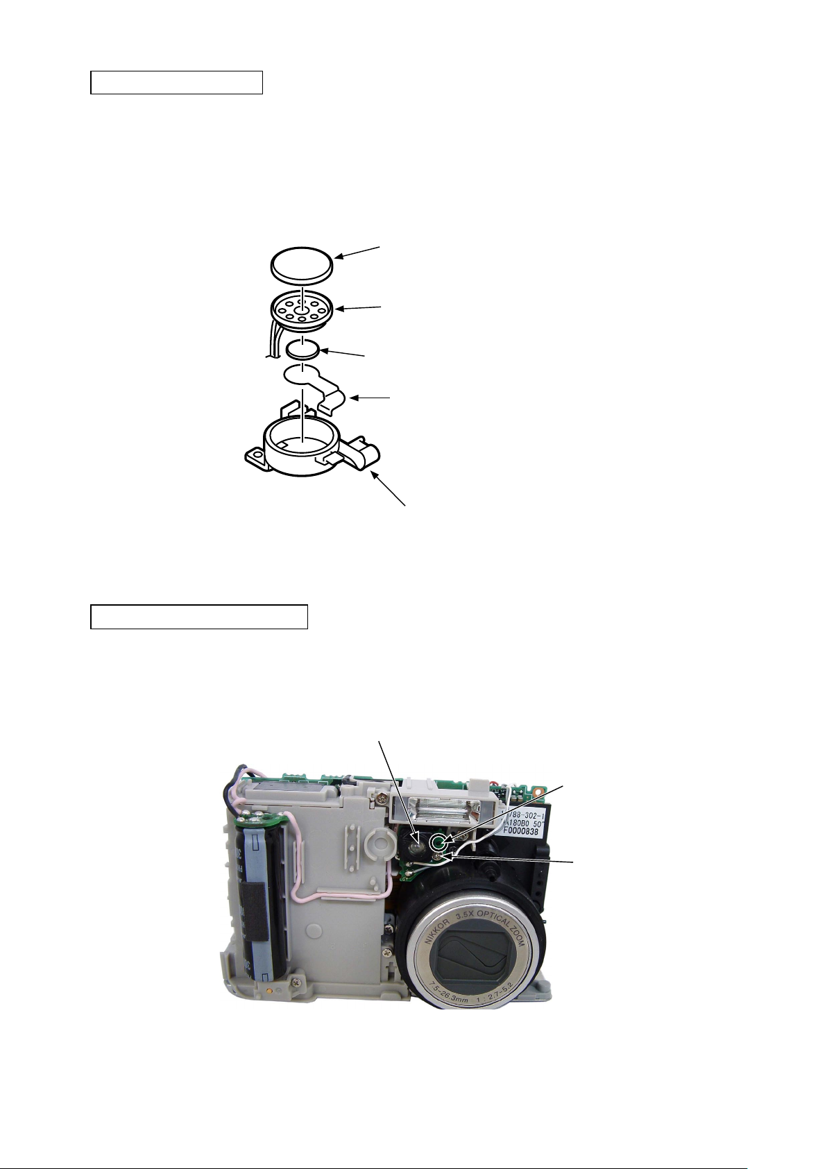
REMOVAL OF SPEAKER
・ Remove the speaker [#1140].
・ Take off the spacer speaker A [#1141].
・ Take off the shield tape speaker A [#1138].
・ Take off the shield tape speaker bottom [#1139].
Shield tape speaker bottom [#1139]
VAA39001-R.3673.A
Spacer speaker A [#1141]
Speaker [#1140]
Shield tape speaker A [#1138]
Holder speaker [#1137]
REMOVAL OF COMPL PWBTB-1
・ Remove the screw [#1210].
・ Remove the COMPL PWBTB-1 [#1123] from the bosses (2 places).
COMPL PWBTB-1 [#1123]
Boss
Screw [#1210]
- D13 ・ P1 -
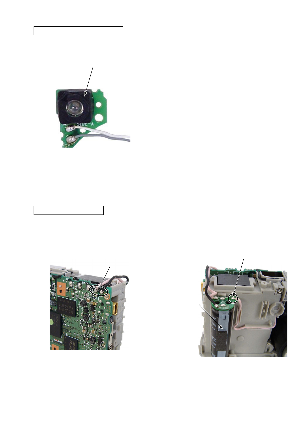
DISASSEMBLY OF COMPL PWBTB-1
・ Remove the holder AF LED [#1122].
Holder AF LED [#1122]
VAA39001-R.3673.A
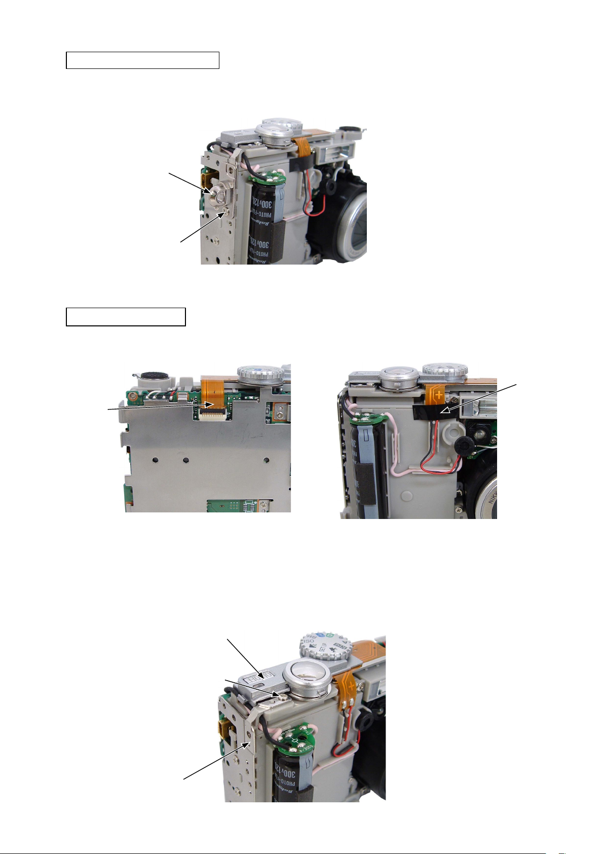
REMOVAL OF CONDENSER
・ Unsolder the lead wires [pink] and [black]. ・ Unsolder the lead wire [pink].
・ Remove the condenser.
Lead wire [pink]
Lead wires [pink] and [black]
Condenser
- D14 ・ P1 -
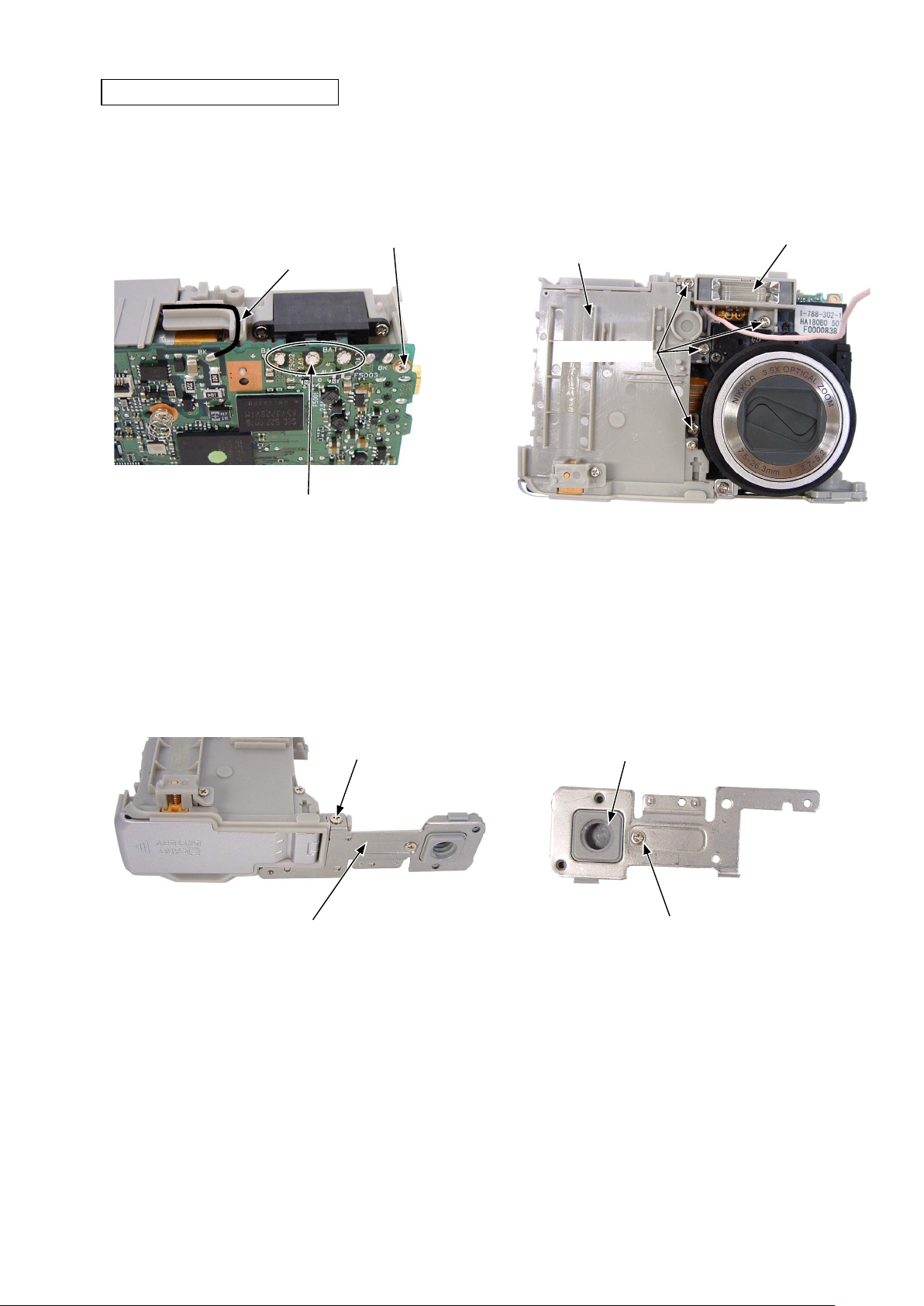
REMOVAL OF BATTERY COVER
VAA39001-R.3673.A
・ Remove the solder (3 places).
・ Unsolder the lead wire [black].
・ Remove the screw [#1204].
Lead wire [black]
Solder
Screw [#1204]
・ Remove the four screws [#1209].
・ Lift the holder flash [#1118] a little and remove the
battery cover.
Holder flash [#1118]
Battery cover
Screw [#1209]
・ Remove the screw [#1209].
・ Remove the holder stand [#1101].
Screw [#1209]
Holder stand [#1101]
・ Remove the screw [#1208].
・ Remove the stand [#1102].
Stand [#1102]
Screw [#1208]
- D15 ・ P1 -
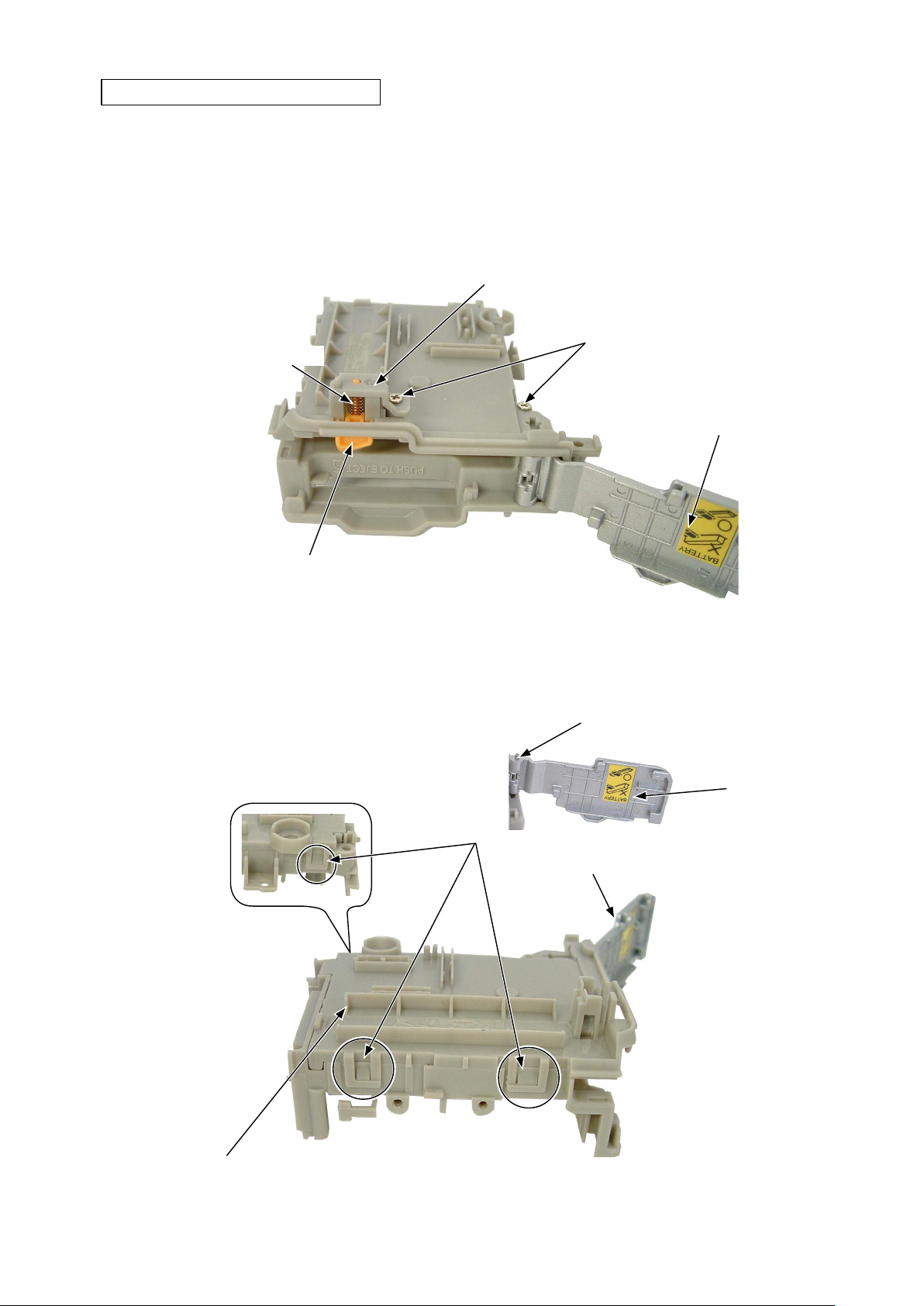
DISASSEMBLY OF BATTERY COVER
・ Open the battery cover [#1104].
・ Remove the two screws [#1204].
・ Remove the holder lever battery [#1111].
・ Remove the spring lever lock [#1110].
・ Remove the lever battery lock [#1109].
VAA39001-R.3673.A
Holder lever battery [#1111]
Spring lever lock [#1110]
Lever battery lock [#1109]
・ Perform unhooking (3 places) and then remove the holder battery front [#1115].
・ The cover battery [#1104] can be removed.
・ The shaft battery [#1103] can be removed.
Screw [#1204]
Shaft battery [#1103]
Cover battery [#1104]
Cover battery
Holder battery front [#1115]
Hook
Cover battery [#1104]
- D16 ・ P1 -
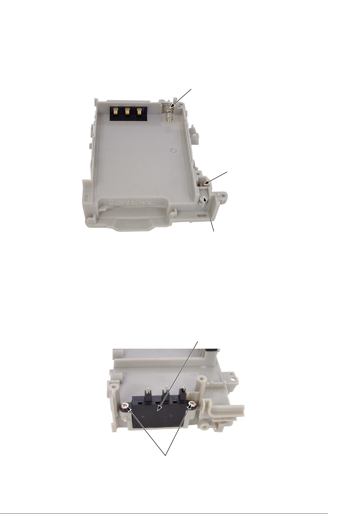
・ Remove the SPRING PAT EJECT [#1116].
・ Remove the LEVER COVER PAT [#1106].
・ The SPRING L COVER PAT [#1107] can be removed.
SPRING PAT EJECT [#1116]
VAA39001-R.3673.A
SPRING L COVER PAT [#1107]
・ Remove the two screws [#1204].
・ Remove the ASSY TERMINAL BATTERY [#1120].
ASSY TERMINAL BATTERY [#1120]
LEVER COVER PAT [#1106]
Screw [#1204]
- D17 ・ P1 -
REMOVAL OF HOLDER FLASH
VAA39001-R.3673.A
・ Take off the spacer [#1147].
・ Unsolder the lead wire [gray].
Lead wire [gray]
・ Remove the holder flash [#1118].
Holder flash [#1118]
Boss
Spacer [#1147]
- D18 ・ P1 -
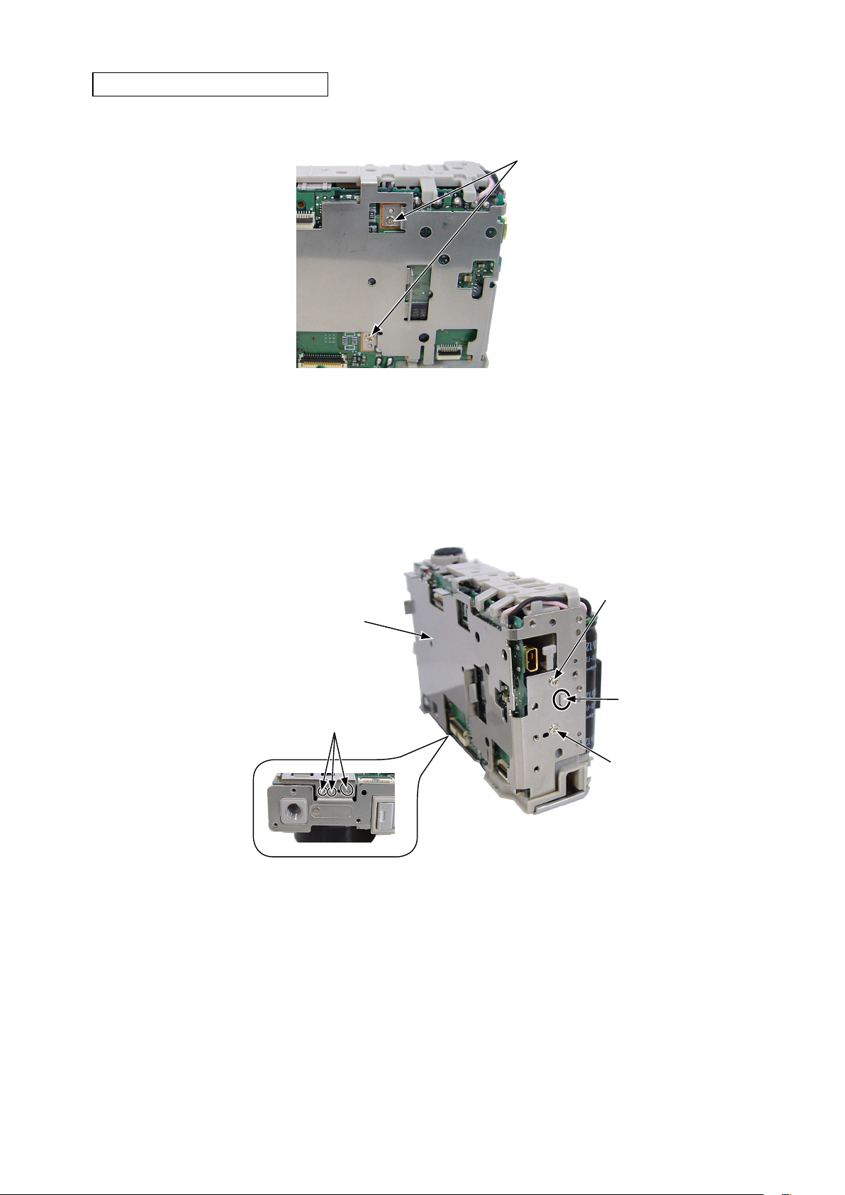
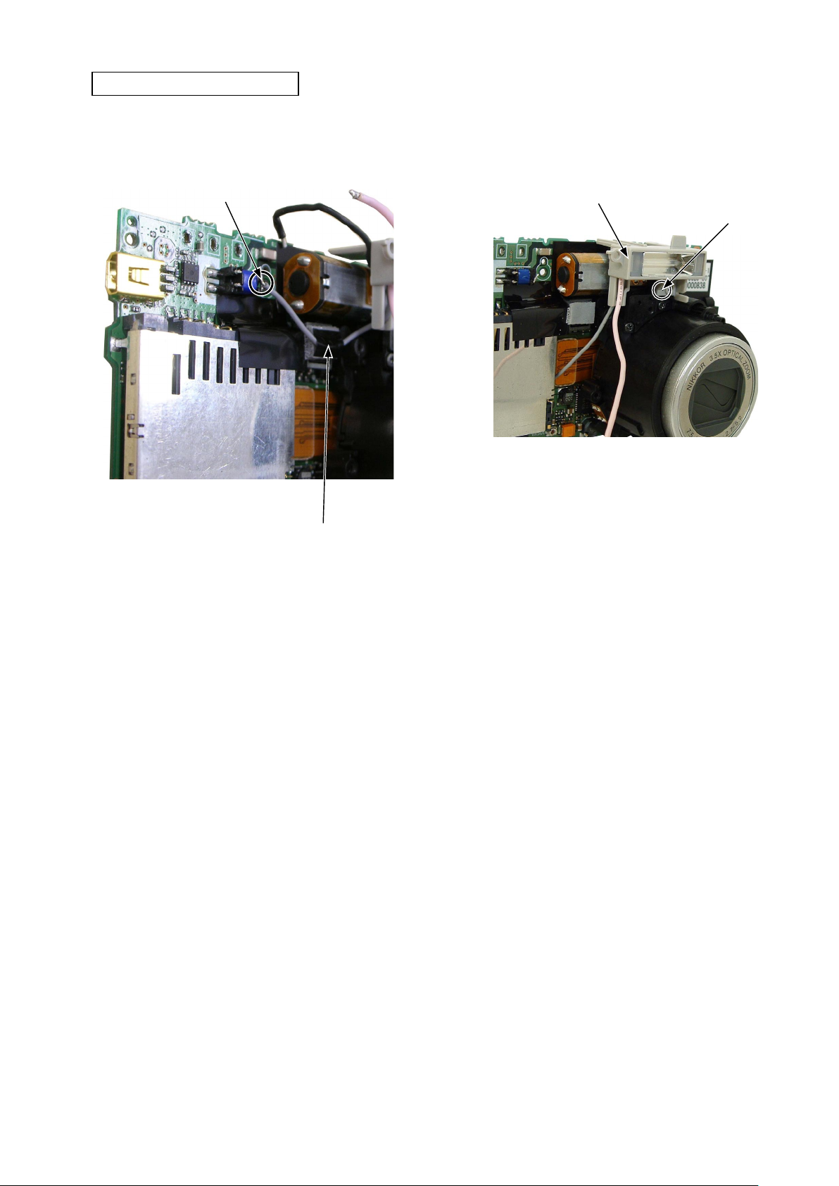
REMOVAL OF COMPL PWBCP-1
・ Remove the connector.
VAA39001-R.3673.A
Connector
・ Remove the FPC.
・ Remove the screw A [#1209].
・ The spring earth zoom [#1131] can be removed.
・ Remove the two screws B [#1209].
・ Remove the COMPL PWBCP-1 [#1142].
Screw B [#1209]
Lens unit
Boss
FPC
COMPL PWBCP-1 [#1142]
Screw A [#1209]
Screw B [#1209]
- D19 ・ P1 -
Spring earth zoom [#1131]
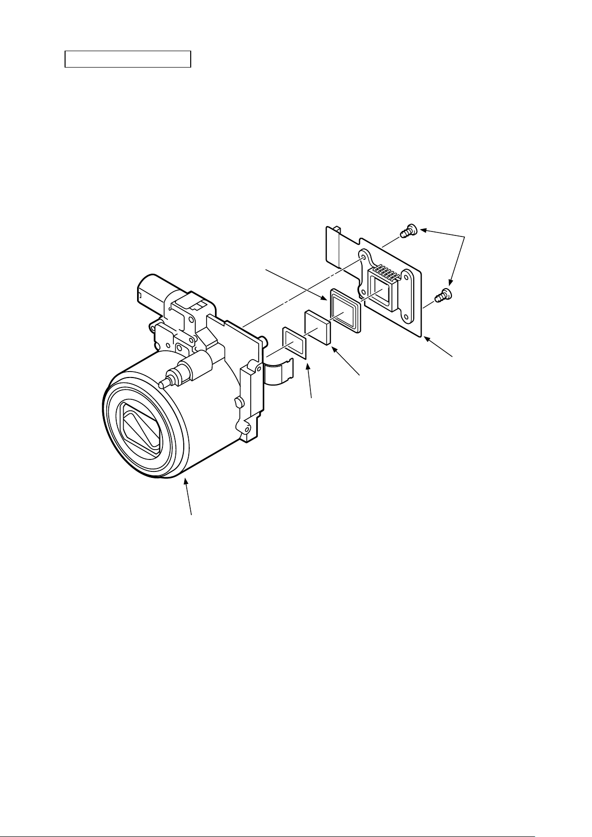
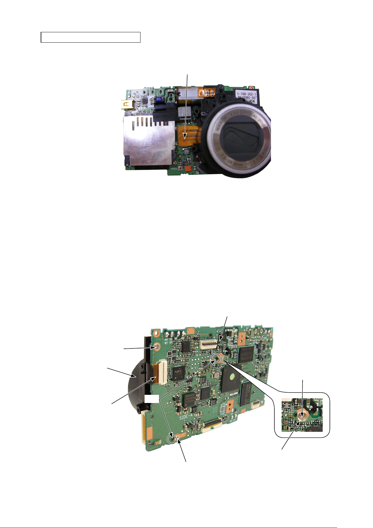
REMOVAL OF LENS UNIT
・ Remove the two screws [#1211].
・ Remove the lens unit.
・ The COMPL CA-1 [#1136] can be removed.
・ The spacer LPF [#1133] can be removed.
・ The optical filter [#1134] can be removed.
・ The spacer [#1135] can be removed.
Spacer [#1135]
VAA39001-R.3673.A
Screw [#1211]
Lens unit
COMPL CA-1 [#1136]
Optical filter [#1134]
Spacer LPF [#1133]
- D20 ・ P1 -

VAA39001-R.3673.A
Points to notice when disassembling/assembling
Lens unit
NOTE : When the following parts are replaced for repairing the lens unit, the lens unit checking tool is required
for the FFD inspection and adjustment. Therefore, at service facilities where there is no such a tool, do
NOT make a replacement.
・ 1st lens group barrel unit (VAA39001-A)
・ Barrier unit (VAA39001-B)
・ 1st lens group unit (VAA39001-A1)
・ 2nd lens group unit (VAA39001-C)
・ CCD mount unit (VAA39001-D)
Tools required for FFD inspection and adjustment
NOTE: When the lens unit is repairede, the following tools are required for the operation check and adjustment
of the lens unit.
・Lens unit checking tool : J61202
・Connection cable for lens : J61203F
・Connection cable for PC : J61204A
・Adjusting focus stand for APS : J15327
・Adapter for J15327 : J15327A
・FFD spacer : J15327H
・P1/P2 lens unit checking program : J65081
- D21 ・ P1 -
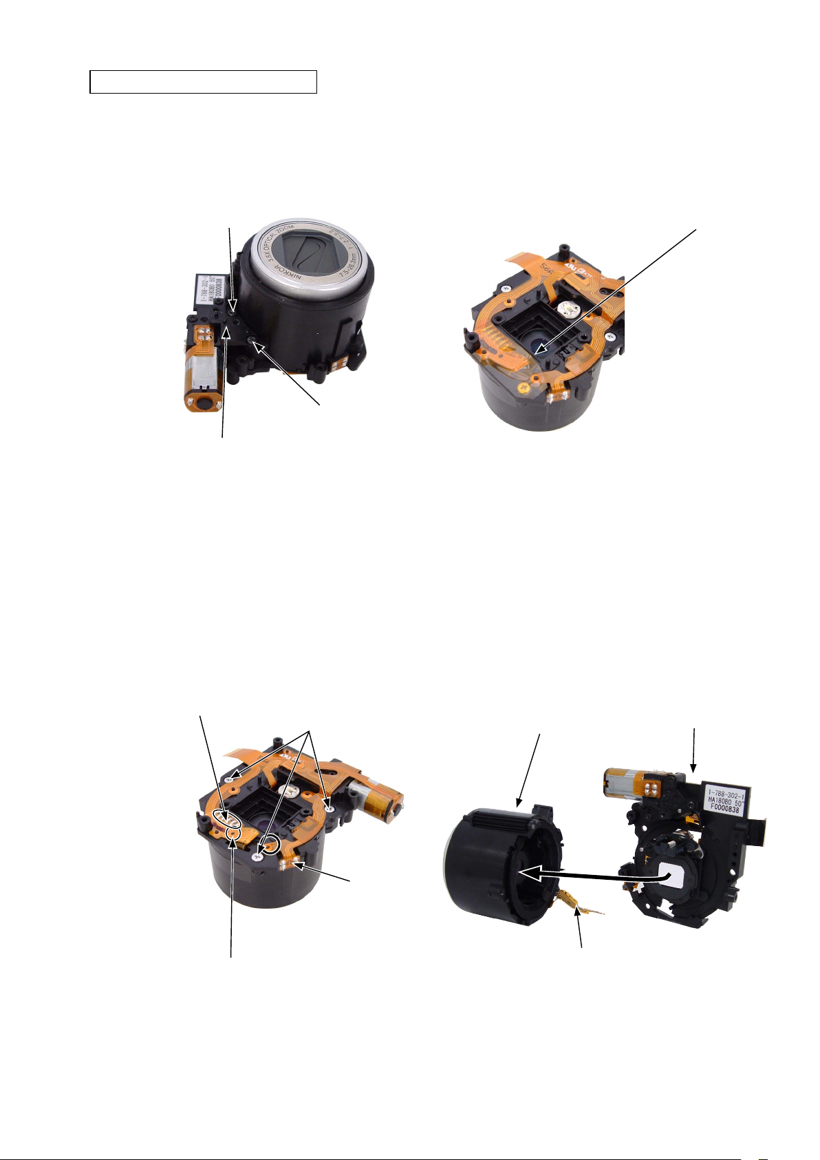
REMOVAL OF LENS BARREL UNIT
VAA39001-R.3673.A
• Remove the two screws [#016-16].
• Remove the AF-assist illuminator mount [#176].
Screw [#016-16]
Screw [#016-16]
AF-assist illuminator mount [#176]
• Take off the FPC retaining tape [#187].
FPC retaining tape [#187]
• Remove the shutter FPC from the boss (A) and perform
unsoldering.
• Remove the three screws [#209-22].
Solder of the shutter FPC
Screw [#209-22]
PI
• As taking care for the shutter FPC, remove the lens barrel
unit.
Lens barrel unit
CCD mount unit
Boss (A)
Shutter FPC
- D22 ・ P1 -
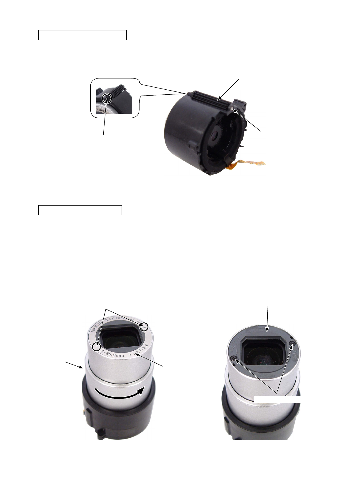
REMOVAL OF KNURLED GEAR
・ Pull out the knurled shaft [#136].
・ The knurled gear [#157] can be removed.
Push out with a pin, etc.
VAA39001-R.3673.A
Knurled gear [#157]
Knurled shaft [#136]
REMOVAL OF BARRIER UNIT
• Turn the cam barrel [#134] leftward and extend the lens
barrel.
• Take off the name plate [#111].
※ Insert the tweezers into the clearance marked with “○”
as shown below and take off the name plate [#111].
In s ert the twe e ze r s in t o on e of th e
clearances and take off the name plate.
Cam barrel [#134]
Name plate [#111]
• Remove the two screws [#10A0-204].
• Remove the barrier unit.
Barrier unit
- D23 ・ P1 -
Screw [#10A0-204]
 Loading...