

Page 1

CNS-9701A
CNS-9701J
CNS-9701K
CENTRAL MONITOR
CNS-9701
0614-006866D
Page 2

Model: CNS-9701A/J/K
Manual code no .: 0614-006866D
We welcome your comments about this man ual. Your comments and suggestions help us improve our
manuals. Please circle the number f or each of the follo wing statements corresponding to your e valuation
and add comments in the space provided.
Fax or send y our completed comment card to:
Fax: +81 (3) 5996-8100
International Div., Sales Promotion Section, Nihon K ohden Corp., 1-31-4, Nishiochiai Shinjuku-ku, Toky o
161-8560, Japan
This manual is organized. 1 2 3 4 5
I can find the information I want. 1 2 3 4 5
The information is accurate. 1 2 3 4 5
I can understand the instructions. 1 2 3 4 5
The illustrations are appropriate and helpful. 1 2 3 4 5
cutting line
The manual length is appropriate. 1 2 3 4 5
Reader Comment Card
Strongly Agree Neutral Disagree Strongly
Agree Disagree
Comments:
Thank you for your cooper ation. We appreciate it very much.
Name:
Occupation/Position:
Hospital/Company:
Address:
Phone:
Page 3

CONTENTS
Contents
GENERAL HANDLING PRECAUTIONS .......................................................................i
WARRANTY POLICY ...................................................................................................ii
Conventions Used in this Manual and Instrument.........................................................v
Warnings, Cautions and Notes ...........................................................................v
Explanations of the Symbols in this Manual and Instrument ..............................v
Section 1 General ...................................................................................1C.1
Introduction ......................................................................................................................... 1.1
Central Monitor Composition .............................................................................................. 1.2
Dual Display Monitoring............................................................................................ 1.3
Network Composition.......................................................................................................... 1.4
Operation Restriction by Monitored Bed Type........................................................... 1.5
Alarm function................................................................................................. 1.5
ST Recall window ........................................................................................... 1.5
Parameter Setup/Personal Setup/Setup ......................................................... 1.5
Operation Restriction Depending on Whether Data Is Stored in the Central Monitor 1.6
Expand Individual Bed Screen............................................................................................ 1.7
Types of Windows............................................................................................................... 1.8
All Beds Screen .............................................................................................. 1.8
Overview Bed Menu Window.......................................................................... 1.9
Menu Window ................................................................................................. 1.9
Individual Bed Screen..................................................................................... 1.9
Review Windows........................................................................................... 1.10
System Setup ............................................................................................... 1.11
Setup ............................................................................................................ 1.11
Personal Setup ............................................................................................. 1.11
Parameter Setup........................................................................................... 1.11
Basic Operation ................................................................................................................ 1.12
Control and Input .................................................................................................... 1.12
Touchscreen Input ........................................................................................ 1.12
Keyboard Input ............................................................................................. 1.12
Mouse Input.................................................................................................. 1.12
Switching Windows ................................................................................................. 1.13
Opening Other Windows from the Menu Screen .......................................... 1.13
Returning to the All Beds Screen ................................................................. 1.13
Returning to the Previous Screen................................................................. 1.13
Opening the Individual Bed Screen from the All Beds Screen...................... 1.13
Changing the Bed to Display or Change Settings......................................... 1.13
Opening Other Windows with Tabs ............................................................... 1.14
Opening Other Windows with Function Keys................................................ 1.14
Changing Settings .................................................................................................. 1.15
Scrolling Data and List............................................................................................ 1.15
Entering Letters and Numbers................................................................................ 1.16
Basic Keyboard Operation...................................................................................... 1.16
Operator's Manual CNS-9701 C.1
Page 4

CONTENTS
Caution Label and Caution Mark ...................................................................................... 1.17
Central Monitor Main Unit ....................................................................................... 1.17
VL-971R/RK LCD Unit ............................................................................................ 1.17
Important Safety Information............................................................................................. 1.18
General................................................................................................................... 1.18
Installation............................................................................................................... 1.19
UPS ........................................................................................................................ 1.19
Network .................................................................................................................. 1.20
Turning the Power On/Off ....................................................................................... 1.21
Discharge and Receiving Channel Change ............................................................ 1.21
Temporary Discharge ............................................................................................. 1.22
Patient Transf er ....................................................................................................... 1.22
Alarm ...................................................................................................................... 1.22
ECG Monitoring ...................................................................................................... 1.23
NIBP Measurement ................................................................................................ 1.23
Maintenance ........................................................................................................... 1.24
Section 2 Panel Description...................................................................2C.1
Central Monitor Main Unit MU-971RA/RJ/RK ..................................................................... 2.1
Front Panel ............................................................................................................... 2.1
Rear Panel................................................................................................................ 2.2
LCD Unit VL-971R/RK ........................................................................................................ 2.3
Front ......................................................................................................................... 2.3
Rear.......................................................................................................................... 2.3
LCD Unit (Locally Purchased Recommended Display)....................................................... 2.4
Recorder Unit WS-971R ..................................................................................................... 2.5
Laser Printer (Network Printer) ........................................................................................... 2.5
UPS .................................................................................................................................... 2.6
Section 3 Preparation.............................................................................3C.1
Installation Conditions......................................................................................................... 3.1
Connecting the Monitor to Other Instruments and Systems ............................................... 3.2
Connecting the Monitor to Other Instruments........................................................... 3.2
Standard Instruments ..................................................................................... 3.2
Optional Instruments ...................................................................................... 3.2
Using a UPS (Uninterruptable Po wer Supply) .......................................................... 3.2
Connecting to a Network System ............................................................................. 3.3
Operation Flowchart ........................................................................................................... 3.4
Loading the Recording Paper ............................................................................................. 3.5
Loading Paper in the WS-971R Recorder Unit ......................................................... 3.5
Loading Paper in the Laser Printer ........................................................................... 3.6
Turning Power On/Off ......................................................................................................... 3.7
Preparation Before Power On ................................................................................... 3.7
Turning the Display and Main Unit Power On ........................................................... 3.7
Starting the Central Monitor System............................................................... 3.8
Turning the Power Off ............................................................................................... 3.8
Turning the WS-971R Recorder Unit Power On........................................................ 3.9
C.2 Operator's Manual CNS-9701
Page 5

CONTENTS
Preparation After Turning the Power On ........................................................................... 3.10
Changing Settings on the System Setup Screen.................................................... 3.10
Before Starting Monitoring ...................................................................................... 3.11
Check Before Use............................................................................................................. 3.12
Check Before Turning On the Monitor..................................................................... 3.12
Check After Turning On the Monitor and During Monitoring ................................... 3.12
Section 4 System Setup Screen ............................................................4C.1
Overview of the System Setup Screen ............................................................................... 4.1
Displaying the System Setup Screen........................................................................ 4.2
Sound Control..................................................................................................................... 4.3
Setting Alarm Sound Volume .................................................................................... 4.3
Setting QRS Sound .................................................................................................. 4.4
Turning the QRS Sound ON/OFF ................................................................... 4.4
Changing the QRS Tone ................................................................................. 4.4
Setting the QRS Bed ...................................................................................... 4.4
Setting QRS Sound Volume ...................................................................................... 4.4
Recording ........................................................................................................................... 4.5
Touchscreen ....................................................................................................................... 4.5
System Configuration Settings............................................................................................ 4.6
Changing Values on the System Configuration Window ........................................... 4.6
Changing Unit Settings ............................................................................................. 4.7
Temperature Unit ............................................................................................ 4.7
Height Unit...................................................................................................... 4.7
Weight Unit ..................................................................................................... 4.7
Pressure Unit.................................................................................................. 4.7
Changing Recording/Printing Settings ...................................................................... 4.7
Report Cover Sheet........................................................................................ 4.7
ECG 12 Lead Printing Format ........................................................................ 4.7
Changing Admitting/Discharging Settings................................................................. 4.8
Discharge Mode ............................................................................................. 4.8
Auto Resume After P ause .............................................................................. 4.8
Alarm Settings .......................................................................................................... 4.8
Telemetry Silence Time .................................................................................. 4.8
Turning Vital Sign Alarm Off Mark Display ON/OFF ....................................... 4.8
Screen Settings ........................................................................................................ 4.8
Setting Screen Timeout .................................................................................. 4.8
Old NIBP Display Setting................................................................................ 4.8
NIBP Effective Time Setting............................................................................ 4.9
All Beds Patient Name Displa y Siz e ............................................................... 4.9
RS-232C Settings ..................................................................................................... 4.9
Monitor Settings................................................................................................................4.10
Displaying the Monitor Setting Windo w................................................................... 4.10
Registering Monitored Beds ................................................................................... 4.11
Data Storage ................................................................................................ 4.12
Setting Bed Name Setting....................................................................................... 4.12
Setting Display Setting............................................................................................ 4.13
Changing the Number of Displays ................................................................ 4.13
Operator's Manual CNS-9701 C.3
Page 6

CONTENTS
Expand Individual Bed Screen...................................................................... 4.13
Changing the Number of Patients Displayed on the Main Display and the
Second Display............................................................................................. 4.13
Setting the All Beds Numeric Area ............................................................... 4.14
ORG Settings....................................................................................................................4.15
Mouse Settings ................................................................................................................. 4.16
Displaying the Mouse Setting Window .................................................................... 4.16
Moving the Mouse to Another Display Unit............................................................. 4.17
Selecting the Mouse Position.................................................................................. 4.18
Selecting the Central Monitor Where Mouse Can Operate..................................... 4.18
Parameters ....................................................................................................................... 4.20
Group Name and Temporary Discharge Message Settings .............................................. 4.21
Displaying the Name Registration Window ............................................................. 4.21
Setting the Group.................................................................................................... 4.22
Editing Group Names ............................................................................................. 4.22
Editing the Message on Temporarily Discharged Beds........................................... 4.23
Setting the Parameter Colors............................................................................................ 4.24
Setting the Alarm Master .................................................................................................. 4.25
Setting Function Keys ....................................................................................................... 4.25
Setting Date & Time.......................................................................................................... 4.26
Maintenance .....................................................................................................................4.28
Confirming Instruments Connected on the Network ............................................... 4.28
Changing the Pass w ord.......................................................................................... 4.29
Enabling/Disabling Screen Hard Copy Printing....................................................... 4.30
Section 5 Admitting/Discharging Patients............................................5C.1
Admitting a Patient.............................................................................................................. 5.1
Patient Attribute Information List ............................................................................... 5.2
Discharging a Patient.......................................................................................................... 5.3
Selecting Discharge Mode or Delete Data Mode...................................................... 5.4
Temporarily Discharging the Patient ................................................................................... 5.5
Resume Monitoring................................................................................................... 5.6
Transferring a Patient to a Different Bedside Monitor.......................................................... 5.7
Changing the Receiving Channel Number........................................................................ 5.10
Section 6 Alarm Function.......................................................................6C.1
Overview of Alarms............................................................................................................. 6.2
Alarm T ypes ........................................................................................................................ 6.2
Alarm Level and Indication.................................................................................................. 6.3
Alarm Level............................................................................................................... 6.3
Alarm Indication ........................................................................................................ 6.3
Alarms on Each Screen ...................................................................................................... 6.4
Alarms for Monitored Beds ....................................................................................... 6.4
Vital Signs Alarm/ST Alarm ............................................................................ 6.4
Arrhythmia Alarm............................................................................................ 6.4
Technical Alarm .............................................................................................. 6.5
Alarms for Overview Bed .......................................................................................... 6.6
C.4 Operator's Manual CNS-9701
Page 7

CONTENTS
Alarms for the Central Monitor and WS-971R Recorder Unit ................................... 6.6
Temporarily Silencing or Suspending Alarms ..................................................................... 6.7
Temporarily Silencing Currently Occurring Alarms ................................................... 6.7
Alarm Silence Time......................................................................................... 6.7
Temporarily Suspending All Alarms .......................................................................... 6.8
Alarm Suspend Time ...................................................................................... 6.8
Suspending All Alarms at the Transmitter ................................................................. 6.8
Alarm Control Marks ........................................................................................................... 6.9
Mark Description....................................................................................................... 6.9
Vital Sign Alarm Off Mark ............................................................................... 6.9
Alarm Off Mark ............................................................................................... 6.9
Alarm Silence Mark/Alarm Suspend Mark...................................................... 6.9
Alarm Silence Mark (from the transmitter)...................................................... 6.9
Alarm Recording Off Mark .............................................................................. 6.9
Priority of Alarm Control Marks ................................................................................ 6.9
Turning the Vital Sign Alarm Off Mark Display On/Off ............................................ 6.10
Alarm Recording ............................................................................................................... 6.11
Alarm Recording Modes ......................................................................................... 6.11
Overview of Alarm Recording ................................................................................. 6.11
Recording Device ......................................................................................... 6.11
Recording Wav eforms .................................................................................. 6.11
Recording Time ............................................................................................ 6.11
Recording Speed.......................................................................................... 6.11
Sensitivity on the Recording Paper............................................................... 6.11
Necessary Settings for Alarm Recording................................................................ 6.11
Vital Sign Alarm Recording........................................................................... 6.12
Arrhythmia Alarm Recording ........................................................................ 6.12
ST Alarm Recording ..................................................................................... 6.12
Starting Automatic Alarm Recording....................................................................... 6.12
Starting Automatic Alarm Recording ............................................................ 6.12
Stopping Automatic Alarm Recording........................................................... 6.12
Setting Alarms ..................................................................................................................6.13
Setting Vital Sign Alarms ........................................................................................ 6.13
Alarm Limits Range ...................................................................................... 6.14
Setting Vital Sign Alarms Automatically (Auto Alarm Setting) ....................... 6.16
Setting the Arrhythmia Alarm.................................................................................. 6.18
Initialization of Arrhythmia Recording ........................................................... 6.18
Alarm Limits Range ...................................................................................... 6.19
Setting the ST Alarm............................................................................................... 6.20
Alarm Limits Range ...................................................................................... 6.21
Setting ST Alarms with Auto Alarm Setting Functions .................................. 6.21
Setting All Alarms to a Preset Pattern (Alarm Master)............................................ 6.22
Turning Signal Loss Alarm On/Off .......................................................................... 6.23
Setting the Lead Off Alarm ..................................................................................... 6.24
Setting an Alarm Master ................................................................................................... 6.25
Setting an Alarm Master ......................................................................................... 6.25
Factory Default Settings of Each Alarm Master...................................................... 6.27
Vital Alarm Master ........................................................................................ 6.27
ST Alarm Master .......................................................................................... 6.30
Operator's Manual CNS-9701 C.5
Page 8

CONTENTS
Arrhythmia Alarm Master.............................................................................. 6.30
Adjusting the Alarm Sound Volume................................................................................... 6.31
Section 7 All Beds Screen......................................................................7C.1
Overview............................................................................................................................. 7.1
Displaying the All Beds Screen................................................................................. 7.1
Screen Description ................................................................................................... 7.2
16 beds (One waveform) ................................................................................ 7.2
12 beds (Two wav eforms) ............................................................................... 7.3
8 beds (Two waveforms)................................................................................. 7.3
6 beds (Two waveforms)................................................................................. 7.4
4 beds (Two waveforms)................................................................................. 7.4
Freezing W av eforms ................................................................................................. 7.5
Temporarily Silencing/Suspending Alarms ............................................................... 7.5
Changing the All Beds Screen Display Setting ................................................................... 7.6
Setting Individually for Each Bed .............................................................................. 7.6
Setting the Sensitivity and Scale of the Displayed Waveform ......................... 7.6
Selecting the Parameter of the Displa yed Wa veform ...................................... 7.7
Selecting the Parameter of the Displa yed Measurement Data ....................... 7.8
Setting the Bed Color.................................................................................... 7.10
Setting for All Beds on the System Configuration Window of the System Setup .... 7.10
Setting for All Beds on the Monitor Setting Windo w of the System Setup............... 7.10
Setting Parameter Priority................................................................................................. 7.11
Recordings on the All Beds Screen .................................................................................. 7.12
All Beds Recording ................................................................................................. 7.12
Necessary Settings for All Beds Recording .................................................. 7.12
Other Recordings ................................................................................................... 7.12
Section 8 Individual Bed Screen ...........................................................8C.1
Overview............................................................................................................................. 8.1
Displaying the Individual Bed Screen ....................................................................... 8.1
Screen Description ................................................................................................... 8.2
Changing Display Types ........................................................................................... 8.4
Changing the Beds ................................................................................................... 8.4
Freezing W av eforms ................................................................................................. 8.4
Temporarily Silencing/Suspending Alarms ............................................................... 8.4
Learning ECG ........................................................................................................... 8.5
Changing the Individual Bed Screen Display Settings ........................................................ 8.6
Setting on the Indiv. Bed Screen Setup Windo w....................................................... 8.6
Selecting the W aveform Sensitivity and Scale on the Wave Display
Window........................................................................................................... 8.6
Selecting the Parameter of the Displa yed Wa veforms on the Wa ve Display
Window........................................................................................................... 8.8
Selecting the Measurement Data Displayed on the Wave Display Window .... 8.9
Changing the Sweep Speed ......................................................................... 8.10
Changing the Sweep Speed of the Respiration Waveform ........................... 8.10
C.6 Operator's Manual CNS-9701
Page 9

CONTENTS
Changing the IBP Waveform Display Mode .................................................. 8.10
Setting on Data Display Windows of the Indiv. Bed Screen .................................... 8.11
Selecting the W aveform Sensitivity and Scale on the Wave Display
Window......................................................................................................... 8.11
Setting Vital Sign Alarms and Measurement Conditions for the Parameters
Displayed on the Indiv. Bed Screen .............................................................. 8.12
Changing the All Bed Screen Display Settings ................................................................. 8.12
Setting Parameter Priority................................................................................................. 8.13
Recording on the Individual Bed Screen........................................................................... 8.14
Dual Wav efo rm Recording ...................................................................................... 8.14
Multi-Wave Printing ................................................................................................. 8.14
ECG 12 Lead Printing............................................................................................. 8.15
Other Recordings ................................................................................................... 8.15
Section 9 Review Windows ....................................................................9C.1
Overview of Review Windows
Overview.......................................................................................................................... 9.0.1
Displaying the Review Window .............................................................................. 9.0.1
Common Description of Review Windows ....................................................................... 9.0.2
Example: Trend windo w ............................................................................... 9.0.2
T rend Window
Overview.......................................................................................................................... 9.1.1
Displaying the Trend Window................................................................................. 9.1.1
Window Description ............................................................................................... 9.1.2
Parameters and Displa y............................................................................... 9.1.3
Viewing Trend Window ..................................................................................................... 9.1.6
Scrolling the Trendgraph ........................................................................................ 9.1.6
Viewing Numerical Data (Cursor Moving).............................................................. 9.1.6
Changing the Display Width of the Trendgraph ...................................................... 9.1.6
Changing the Trend Window Displa y Setting ................................................................... 9.1.7
Setting the Displayed Parameters.......................................................................... 9.1.7
Changing the Scale ............................................................................................... 9.1.7
Selecting Displayed Ev ents ................................................................................... 9.1.8
Printing T rendgraphs........................................................................................................ 9.1.9
Other Recordings ........................................................................................ 9.1.9
T abular T rend Window
Overview.......................................................................................................................... 9.2.1
Displaying the T ab ular Trend Window..................................................................... 9.2.1
Window Description ............................................................................................... 9.2.2
Viewing the T abular Trend Window................................................................................... 9.2.3
Scrolling the Tabular Trend..................................................................................... 9.2.3
Displaying a Different Tabular Trend....................................................................... 9.2.3
Changing the T abular Trend Window Display Setting ....................................................... 9.2.4
Changing the Display Interval................................................................................ 9.2.4
Setting the Patterns of Tabular Trend ..................................................................... 9.2.4
Selecting Parameters for Each Tabular Trend .............................................. 9.2.4
Operator's Manual CNS-9701 C.7
Page 10

CONTENTS
Registering Names for Each Tabular Trend.................................................. 9.2.6
Printing T ab ular T rend ...................................................................................................... 9.2.7
Other Recordings ........................................................................................ 9.2.7
Hemodynamics Window
Overview.......................................................................................................................... 9.3.1
Displaying the Hemodynamics List Windo w .......................................................... 9.3.1
Window Description ............................................................................................... 9.3.1
Viewing the Hemodynamics List Window......................................................................... 9.3.2
Scrolling the Hemodynamics List........................................................................... 9.3.2
Abbreviations ................................................................................................................... 9.3.3
Printing the Hemodynamics List ...................................................................................... 9.3.4
Other Recordings ........................................................................................ 9.3.4
Arrhythmia Recall Window
Overview.......................................................................................................................... 9.4.1
Displaying the Arrhythmia Recall Window.............................................................. 9.4.1
Window Description ............................................................................................... 9.4.2
File List Window........................................................................................... 9.4.2
Expanded Wav eform Window ...................................................................... 9.4.3
Viewing the Arrhythmia Recall Window............................................................................ 9.4.4
Scrolling the List of Arrhythmia Recall Files........................................................... 9.4.4
Sorting the List....................................................................................................... 9.4.4
Displaying Expanded Arrhythmia Recall Wave form ............................................... 9.4.4
Displaying Another File................................................................................ 9.4.5
Changing the Number of Waveforms........................................................... 9.4.5
Scrolling Multiple W aveforms....................................................................... 9.4.6
Annotation List on the Expanded Waveform Window .................................. 9.4.6
Measuring Arrhythmia Recall Waveform with Caliper ............................................ 9.4.7
Changing Display Zoom and Sweep Speed ................................................ 9.4.8
Selecting the Measured W aveform (Multiple Waveform Display Only) ........ 9.4.8
Deleting All Measurement Results............................................................... 9.4.8
Ending Caliper Measurement ...................................................................... 9.4.8
Deleting Arrhythmia Recall Files...................................................................................... 9.4.9
Automatic Deletion................................................................................................. 9.4.9
Deleting Unnecessary Arrhythmia Recall Files...................................................... 9.4.9
Deleting Files with Deletion Marks .............................................................. 9.4.9
Deleting the File Displayed on the Expanded Waveform Window.............. 9.4.10
Setting Arrhythmia Recall File Creation ......................................................................... 9.4.11
Priority of Creating Arrhythmia Recall Files ......................................................... 9.4.11
Selecting the Arrhythmia Types Displayed on the File List............................................. 9.4.12
Recording on the Arrhythmia Recall Windo w................................................................. 9.4.13
Arrhythmia Recall Recording ............................................................................... 9.4.13
Recording/Printing Displayed Files............................................................ 9.4.13
Printing Files with Printing Marks .............................................................. 9.4.13
Printing Caliper Measurement Data..................................................................... 9.4.14
Other Recordings ................................................................................................ 9.4.14
C.8 Operator's Manual CNS-9701
Page 11

CONTENTS
ST Recall Window
Overview.......................................................................................................................... 9.5.1
Displaying the ST Recall Windo w .......................................................................... 9.5.1
Window Description ............................................................................................... 9.5.2
Viewing the ST Recall Window ........................................................................................ 9.5.3
Scrolling the ST Recall Files.................................................................................. 9.5.3
Scrolling the ST Waveform .................................................................................... 9.5.3
Changing ST Recall Window Display Settings ................................................................. 9.5.4
Setting the Display Position of the ST Waveform ................................................... 9.5.4
Changing Sensitivity .............................................................................................. 9.5.5
Setting ST Analysis Method................................................................................... 9.5.5
Changing the Interval............................................................................................. 9.5.5
Recordings on the ST Recall Window.............................................................................. 9.5.6
ST Recall Recording.............................................................................................. 9.5.6
Recording a Selected File............................................................................ 9.5.6
Printing Files................................................................................................ 9.5.6
Other Recordings .................................................................................................. 9.5.6
Full Disclosure Window
Overview.......................................................................................................................... 9.6.1
Displaying the Full Disclosure Screen ................................................................... 9.6.1
Window Description ............................................................................................... 9.6.2
Compressed Wav ef orm Display................................................................... 9.6.2
Expanded Waveform Display (Actual Size Display)..................................... 9.6.3
Stored Waveforms and Displayed Waveforms ............................................. 9.6.4
Display Color ............................................................................................... 9.6.4
T riangle W av eform ....................................................................................... 9.6.4
Viewing the Full Disclosure Window ................................................................................ 9.6.5
Scrolling the Full Disclosure Waveform.................................................................. 9.6.5
Automatic Scroll........................................................................................... 9.6.5
Expanding the Full Disclosure Waveform into Actual Size..................................... 9.6.6
Measuring an Full Disclosure Waveform with the Calipers .................................... 9.6.7
Changing Display Zoom and Sweep Speed ................................................ 9.6.8
Selecting the Measured W aveform .............................................................. 9.6.8
Deleting All Measurement Results............................................................... 9.6.8
Ending Caliper Measurement ...................................................................... 9.6.8
Waveform Storage Setup ................................................................................................. 9.6.9
Changing the Full Disclosure Window Display ............................................................... 9.6.10
Changing the Displayed Waveforms .................................................................... 9.6.10
Changing the Sensitivity and Scale ..................................................................... 9.6.11
Recordings on the Full Disclosure Window.................................................................... 9.6.12
Full Disclosure W aveform Printing ....................................................................... 9.6.12
Recording/Printing Expanded Wa veform ............................................................. 9.6.12
Printing Caliper Measurement Data..................................................................... 9.6.13
Other Recordings ................................................................................................ 9.6.13
ECG 12 Lead Window
Overview.......................................................................................................................... 9.7.1
Displaying the ECG 12 Lead Analysis Windo w...................................................... 9.7.1
Operator's Manual CNS-9701 C.9
Page 12

CONTENTS
Window Description ............................................................................................... 9.7.2
T ab ular Trend Displa y .................................................................................. 9.7.2
Zoom In Display........................................................................................... 9.7.3
Comparison Display .................................................................................... 9.7.3
Analysis Report Display............................................................................... 9.7.4
Viewing the ECG 12 Lead Analysis Windo w.................................................................... 9.7.5
Changing the Display Types................................................................................... 9.7.5
T ab ular Trend Displa y .................................................................................. 9.7.5
Zoom In Display........................................................................................... 9.7.5
Comparison Display .................................................................................... 9.7.5
Analysis Report Display............................................................................... 9.7.6
Scrolling the Files in the Measurement Value Table............................................... 9.7.6
Selecting the Displayed File................................................................................... 9.7.6
Selecting the Control File....................................................................................... 9.7.6
Switching Displayed Waveform Types.................................................................... 9.7.7
Deleting ECG 12 Lead Analysis Files .............................................................................. 9.7.8
Automatic Deletion................................................................................................. 9.7.8
Deleting Unnecessary ECG 12 Lead Analysis Files .............................................. 9.7.8
Recordings on the ECG 12 Lead Analysis Window ......................................................... 9.7.9
Other Recordings .................................................................................................. 9.7.9
Alarm History Window
Overview.......................................................................................................................... 9.8.1
Displaying the Alarm History Window .................................................................... 9.8.1
Window Description ............................................................................................... 9.8.2
Viewing the Alarm History Window .................................................................................. 9.8.3
Scrolling the Alarm History .......................................................................... 9.8.3
Sorting the List ............................................................................................ 9.8.3
Selecting the Alarm Levels and Types Displayed on the File List .................................... 9.8.4
Recordings on the Alarm History Window ....................................................................... 9.8.5
Alarm History Recording ............................................................................. 9.8.5
Recording a Selected File.................................................................. 9.8.5
Other Recordings ........................................................................................ 9.8.5
Report Window
Overview.......................................................................................................................... 9.9.1
Displaying the Report Window............................................................................... 9.9.1
Window Description ............................................................................................... 9.9.1
Report Mode .......................................................................................................... 9.9.2
Manual Printing............................................................................................ 9.9.2
Automatic Printing........................................................................................ 9.9.2
Printing Items......................................................................................................... 9.9.2
Report Creating Flowchart..................................................................................... 9.9.2
Changing Report Settings................................................................................................ 9.9.3
Setting Printing Format .......................................................................................... 9.9.3
Setting the Report Mode.............................................................................. 9.9.3
Selecting Printing Items ............................................................................... 9.9.3
Setting Report Range .................................................................................. 9.9.3
Setting Trend Data Printing .................................................................................... 9.9.5
C.10 Operator's Manual CNS-9701
Page 13

CONTENTS
Changing T rend Interval............................................................................... 9.9.5
Changing Printing Parameters..................................................................... 9.9.5
Entering Comments ......................................................................................................... 9.9.6
Using Template to Enter a Comment ........................................................... 9.9.6
Printing on the Report Window ........................................................................................ 9.9.7
Manual Printing............................................................................................ 9.9.7
Automatic Printing........................................................................................ 9.9.7
Section 10 Recording .............................................................................10C.1
Overview........................................................................................................................... 10.1
Description of Recording Modes............................................................................. 10.2
Manual Recording ........................................................................................ 10.2
Automatic Recording .................................................................................... 10.3
Remote Recording........................................................................................ 10.4
Recording Priority ................................................................................................... 10.5
Recorder unit (WS-971R) ............................................................................. 10.5
Laser Printer ................................................................................................. 10.5
Recording Sensitivity .............................................................................................. 10.6
Recorded/Printed Data ........................................................................................... 10.6
Manual Recording............................................................................................................. 10.7
Delayed W av eform Recording ................................................................................ 10.7
Necessary Settings for Delayed Waveform Recording ................................. 10.7
Starting Delayed Waveform Recording......................................................... 10.7
Automatic W avef orm Recording........................................................................................ 10.8
Periodic Recording ................................................................................................. 10.8
Necessary Settings for Periodic Recording .................................................. 10.8
Alarm Recording ..................................................................................................... 10.8
Remote Recording............................................................................................................ 10.9
Necessary Settings for Remote Recording............................................................. 10.9
Call Recording .............................................................................................. 10.9
Remote Recording........................................................................................ 10.9
Starting Remote Recording .................................................................................... 10.9
Call Recording .............................................................................................. 10.9
Remote Delayed Waveform Recording......................................................... 10.9
Changing Recording Settings ......................................................................................... 10.10
Changing Settings on the Recording Window of the Setup .................................. 10.10
Changing Alarm Recording Settings........................................................... 10.11
Setting Recording Waveforms for Dual Waveform Recording..................... 10.12
Changing Recording Interval of Periodic Recording ................................... 10.12
Setting the Record Sweep Speed............................................................... 10.13
Changing Settings on the Recording Window of the System Setup Screen......... 10.14
Displaying the Recording Window of the System Setup Screen................. 10.14
Changing the Recording Time .................................................................... 10.14
Adjusting the Grid Darkness....................................................................... 10.15
Section 11 Overview Bed Screen ..........................................................11C.1
Overview........................................................................................................................... 11.1
Operator's Manual CNS-9701 C.11
Page 14

CONTENTS
Displaying the Overview Bed Menu Screen............................................................ 11.1
Alarm Function for an Overview Bed ...................................................................... 11.2
Screen Description ................................................................................................. 11.2
Selecting Another Bedside Monitor as an Overview Bed.................................................. 11.3
Switching to Other Windows of the Overview Bed Screen................................................ 11.3
Recordings on the Overview Bed Screen ......................................................................... 11.3
Section 12 Parameter Setup ..................................................................12C.1
Overview of Parameter Setup........................................................................................... 12.1
Displaying Each Par ameter Setup Window............................................................. 12.2
ECG Settings .................................................................................................................... 12.3
Setting Vital Sign Alarms ........................................................................................ 12.3
Setting Arrhythmia Alarms ...................................................................................... 12.3
Setting the Analysis Lead ....................................................................................... 12.4
Setting QRS Detection............................................................................................ 12.4
Setting QRS Detection Settings.................................................................... 12.4
Setting QRS Detection Sensitivity in Auto Detection .................................... 12.5
Setting QRS Detection Lead and Threshold in Manual Detection ................ 12.5
Setting ECG Lead Name ........................................................................................ 12.6
ST Settings ............................................................................................................. 12.6
Setting the ST Analysis Method.................................................................... 12.6
Setting the ST Interval .................................................................................. 12.7
Setting Other Settings............................................................................................. 12.8
Setting Electrode Lead Off Alarm ................................................................. 12.8
Turning Noise Alarm ON/OFF....................................................................... 12.8
Turning Arrhythmia Analysis ON/OFF .......................................................... 12.8
Turning Pacing Detection ON/OFF ............................................................... 12.9
Turning Hum Filter ON/OFF.......................................................................... 12.9
Turning Pacing Marker ON/OFF ................................................................... 12.9
Respiration Settings........................................................................................................ 12.10
Setting the Vital Sign Alarm .................................................................................. 12.10
Turning the Impedance Respiration Measurement ON/OFF................................. 12.10
Changing the Respiration Detection Sensitivity .................................................... 12.11
SpO2 Settings ................................................................................................................. 12.12
Setting the Vital Sign Alarm .................................................................................. 12.12
Turning the SpO2 Status Alarm ON/OFF .............................................................. 12.12
NIBP Settings ................................................................................................................. 12.13
Setting the Vital Sign Alarm .................................................................................. 12.13
Setting NIBP Measurement Mode and Measurement Interval.............................. 12.13
Starting/Stopping NIBP Measurement .................................................................. 12.14
PRESS Settings.............................................................................................................. 12.15
Setting the Vital Sign Alarm .................................................................................. 12.15
Changing the Display P attern and the Blood Pressure Label ............................... 12.16
Temp Settings ................................................................................................................. 12.17
Setting the Vital Sign Alarm .................................................................................. 12.17
Setting the Label for Temperature Measurement Sites and Equation for ∆T......... 12.17
CO2 Settings ................................................................................................................... 12.19
Setting the Vital Sign Alarm .................................................................................. 12.19
C.12 Operator's Manual CNS-9701
Page 15

CONTENTS
FiO2 Settings................................................................................................................... 12.20
Setting the Vital Sign Alarm .................................................................................. 12.20
Anesthesia Gas Settings ................................................................................................ 12.21
Setting the Vital Sign Alarm .................................................................................. 12.21
Setting the Displayed Parameters of Waveforms and Numerical Data ................. 12.21
V entilator Settings........................................................................................................... 12.22
Section 13 Personal Setup and Setup...................................................13C.1
Overview of Personal Setup and Setup ............................................................................ 13.1
Displaying Each Setting Window ............................................................................ 13.1
Section 14 Error Messages and T roubleshooting ................................14C.1
Troubleshooting................................................................................................................. 14.1
System.................................................................................................................... 14.1
Network .................................................................................................................. 14.2
Measurement V alue ................................................................................................ 14.3
Alarm ...................................................................................................................... 14.3
Admitting/Discharging............................................................................................. 14.4
All Beds Screen/Individual Bed Screen .................................................................. 14.5
Trend Window ......................................................................................................... 14.6
T ab ular Trend Window............................................................................................. 14.6
Hemodynamics List Window................................................................................... 14.6
Arrhythmia Recall Windo w...................................................................................... 14.7
ST Recall Window................................................................................................... 14.7
Full Disclosure Window........................................................................................... 14.8
ECG 12 Lead Analysis Window .............................................................................. 14.8
Report Window ....................................................................................................... 14.9
Recording ............................................................................................................... 14.9
Overview Bed Screen ........................................................................................... 14.10
Parameter Setup................................................................................................... 14.10
Error Messages .............................................................................................................. 14.11
Messages From Bedside Monitors/Multiple Patient Receiver ............................... 14.11
Messages about Measurement Conditions of Each Parameter.................. 14.11
Other .......................................................................................................... 14.16
Messages From Central Monitor........................................................................... 14.17
WS-971R Recorder Unit............................................................................. 14.17
Laser Printer ............................................................................................... 14.17
Other .......................................................................................................... 14.17
Daily Check..................................................................................................................... 14.18
Checking Sound Generation from the Speaker .................................................... 14.18
Calibrating the Touchscreen ................................................................................. 14.18
Adjusting the VL-971R/RK LCD Unit..................................................................... 14.21
Printing a Screen Hard Copy .......................................................................................... 14.21
Inspection After Use ....................................................................................................... 14.22
Cleaning, Disinfecting and Sterilization........................................................................... 14.23
Central Monitor ..................................................................................................... 14.23
Cleaning the Main Unit ............................................................................... 14.23
Operator's Manual CNS-9701 C.13
Page 16

CONTENTS
Disinfecting the Main Unit ........................................................................... 14.23
Cleaning the Display................................................................................... 14.24
WS-971R Recorder Unit ....................................................................................... 14.24
Thermal Head............................................................................................. 14.24
Sensor ........................................................................................................ 14.24
Regular Inspection.......................................................................................................... 14.25
Periodical Replacement Schedule .................................................................................. 14.26
Repair Parts Availability Policy........................................................................................ 14.26
Section 15 Reference..............................................................................15C.1
Factory Default Settings.................................................................................................... 15.1
All Beds Screen/Individual Bed Screen .................................................................. 15.1
Review Window....................................................................................................... 15.2
Parameter Setup..................................................................................................... 15.3
Personal Setup ....................................................................................................... 15.4
Setup ...................................................................................................................... 15.4
System Setup ......................................................................................................... 15.5
Parameter Priority............................................................................................................. 15.7
Initializing the System ....................................................................................................... 15.8
Specification ..................................................................................................................... 15.9
Display.................................................................................................................... 15.9
Waveform Display Items ......................................................................................... 15.9
Alphanumeric Display Items ................................................................................... 15.9
Sound ..................................................................................................................... 15.9
Alarm Function ....................................................................................................... 15.9
Trend..................................................................................................................... 15.10
Waveform Sensitivity ............................................................................................ 15.10
Overview............................................................................................................... 15.10
Remote Setting ..................................................................................................... 15.10
Full Disclosure ...................................................................................................... 15.10
File Saving ............................................................................................................ 15.10
2-ch Recorder, WS-971R (option)......................................................................... 15.11
Laser Printer (local purchase) .............................................................................. 15.11
Po w er Requirements ............................................................................................ 15.11
Environment.......................................................................................................... 15.12
Electromagnetic Compatibility .............................................................................. 15.12
Safety.................................................................................................................... 15.12
Dimensions and W eight ........................................................................................ 15.12
Standard Accessories..................................................................................................... 15.13
MU-971RJ Main Unit ............................................................................................ 15.13
MU-971RK Main Unit............................................................................................ 15.14
MU-971RA Main Unit............................................................................................ 15.15
Options and Consumables.............................................................................................. 15.16
Options ................................................................................................................. 15.16
Consumables........................................................................................................ 15.16
General Requirements for Connecting Medical Electrical System.................................. 15.17
C.14 Operator's Manual CNS-9701
Page 17

GENERAL HANDLING PRECAUTIONS
This device is intended for use only by qualified medical personnel.
Use only Nihon Kohden approved products with this device. Use of non-approved products or in
a non-approved manner may affect the performance specifications of the device. This includes,
but is not limited to, batteries, recording paper, pens, extension cables, electrode leads, input
boxes and AC power.
Please read these precautions thoroughly before attempting to operate the instrument.
1. To safely and effectively use the instrument, its operation must be fully understood.
2. When installing or storing the instrument, take the following precautions:
(1) Avoid moisture or contact with water, extreme atmospheric pressure, excessive humidity and temperatures, poorly
ventilated areas, and dust, saline or sulphuric air.
(2) Place the instrument on an even, level floor. Avoid vibration and mechanical shock, even during transport.
(3) Avoid placing in an area where chemicals are stored or where there is danger of gas leakage.
(4) The power line source to be applied to the instrument must correspond in frequency and voltage to product
specifications, and have sufficient current capacity.
(5) Choose a room where a proper grounding facility is available.
3. Before Operation
(1) Check that the instrument is in perfect operating order.
(2) Check that the instrument is grounded properly.
(3) Check that all cords are connected properly.
(4) Pay extra attention when the instrument is in combination with other instruments to avoid misdiagnosis or other
problems.
(5) All circuitry used for direct patient connection must be doubly checked.
(6) Check that battery level is acceptable and battery condition is good when using battery-operated models.
4. During Operation
(1) Both the instrument and the patient must receive continual, careful attention.
(2) Turn power off or remove electrodes and/or transducers when necessary to assure the patient’s safety.
(3) Avoid direct contact between the instrument housing and the patient.
5. To Shutdown After Use
(1) Turn power off with all controls returned to their original positions.
(2) Remove the cords gently; do not use force to remove them.
(3) Clean the instrument together with all accessories for their next use.
6. The instrument must receive expert, professional attention for maintenance and repairs. When the instrument is
not functioning properly, it should be clearly marked to avoid operation while it is out of order.
7. The instrument must not be altered or modified in any way.
8. Maintenance and Inspection:
(1) The instrument and parts must undergo regular maintenance inspection at least every 6 months.
(2) If stored for extended periods without being used, make sure prior to operation that the instrument is in perfect
operating condition.
Operator's Manual CNS-9701 i
Page 18

(3) Technical information such as parts list, descriptions, calibration instructions or other information is available for
qualified user technical personnel upon request from your Nihon Kohden distributor.
9. When the instrument is used with an electrosurgical instrument, pay careful attention to the application and/or
location of electrodes and/or transducers to avoid possible burn to the patient.
10. When the instrument is used with a defibrillator, make sure that the instrument is protected against defibrillator
discharge. If not, remove patient cables and/or transducers from the instrument to avoid possible damage.
WARRANTY POLICY
Nihon Kohden Corporation (NKC) shall warrant its products against all defects in materials and workmanship for one year
from the date of delivery. However, consumable materials such as recording paper, ink, stylus and battery are excluded from
the warranty.
NKC or its authorized agents will repair or replace any products which prove to be defective during the warranty period,
provided these products are used as prescribed by the operating instructions given in the operator’s and service manuals.
No other party is authorized to make any warranty or assume liability for NKC’s products. NKC will not recognize any other
warranty, either implied or in writing. In addition, service, technical modification or any other product change performed by
someone other than NKC or its authorized agents without prior consent of NKC may be cause for voiding this warranty.
Defective products or parts must be returned to NKC or its authorized agents, along with an explanation of the failure.
Shipping costs must be pre-paid.
This warranty does not apply to products that have been modified, disassembled, reinstalled or repaired without Nihon
Kohden approval or which have been subjected to neglect or accident, damage due to accident, fire, lightning, vandalism,
water or other casualty, improper installation or application, or on which the original identification marks have been
removed.
In the USA and Canada other warranty policies may apply.
CAUTION
United States law restricts this device to sale by or on the order of a physician.
ii Operator's Manual CNS-9701
Page 19

EMC RELATED CAUTION
This equipment and/or system complies with the International Standard IEC 60601-1-2 for electr omagnetic
compatibility for medical electrical equipment and/or system. However, an electromagnetic environment
that exceeds the limits or levels stipulated in the IEC 60601-1-2, can cause harmful interference to the
equipment and/or system or cause the equipment and/or system to fail to perform its intended function or
degrade its intended performance. Therefore, during the operation of the equipment and/or system, if
there is any undesired deviation from its intended operational performance, you must avoid, identify and
resolve the adverse electroma gnetic effect before continuing to use the equipment and/or system.
The following describes some common interference sources and remedial actions:
1. Strong electromagnetic interference from a nearby emitter source such as an authorized radio station
or cellular phone:
Install the equipment and/or system at another location if it is interfered with by an emitter source such
as an authorized radio station. Keep the emitter source such as cellular phone away from the
equipment and/or system.
2. Radio-frequency interference from other equipment through the AC power supply of the equipment
and/or system:
Identify the cause of this interference and if possible remove this interference sour c e. If this is not
possible, use a different power supply.
3. Effect of direct or indirect electrostatic discharge:
Make sure all users and patients in contact with the equipment and/or system are free from direct or
indirect electrostatic energy before using it. A humid room can help lessen this problem.
4. Electromagnetic interference with any radio wave receiver such as radio or television:
If the equipment and/or system interferes with any radio wave receiver, locate the equipment and/or
system as far as possible from the radio wave receiver.
If the above suggested remedial actions do not solve the problem, consult your Nihon Kohden Corporation
subsidiary or distributor for additional suggestions.
The CE mark is a protected conformity mark of the European Community. The products herewith comply
with the requirements of the Medical Device Directive 93/42/EEC.
The CE mark only applies to the CNS-9701K series central monitors.
This equipment complies with EUROPEAN STANDARD EN-60601-1-2 (1993) which requires EN-55011, class
A. Class A EQUIPMENT is allowed in domestic establishments when used under the jurisdiction of a
health care professional.
Operator's Manual CNS-9701 iii
Page 20

In IEC 60601-1-2 Medical Electronic Equipment, Part 1: General Requirements for Safety, 2. Collateral
Standard: Electromagnetic compatibility-Requirements and test. Section 36. 202. 2 Radiated radiofrequency electromagnetic fields, PATIENT COUPLED EQUIPMENT and/or SYSTEMS applicable IMMUNITY
test methods are under consideration at SC62A/WG13. The 3 V/m IMMUNITY level may be inappropriate
especially when measuring SpO2 because physiological signals can be much smaller than those induced
by a 3 V/m electromagnetic field.
When measuring SpO2, various interference may produce false waveforms which look like pulse
waveforms. SpO2 value and pulse rate may be measured from these false waveforms, causing the alarm to
function improperly.
When installing the monitor, avoid locations where the monitor may receive strong electromagnetic
interference such as radio or TV stations, cellular phone or mobile two-way radios.
iv Operator's Manual CNS-9701
Page 21
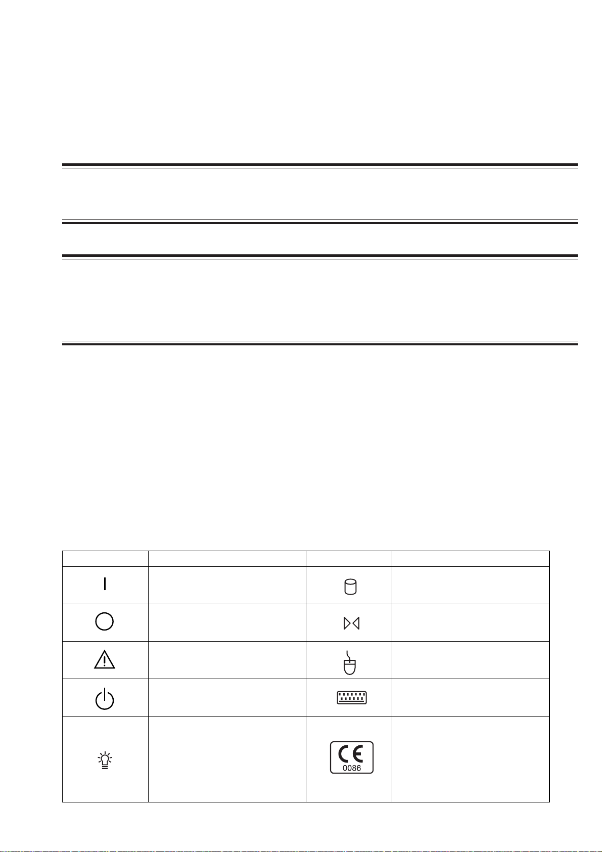
Conventions Used in this Manual and Instrument
Warnings, Cautions and Notes
Warnings, cautions and notes are used in this manual to alert or signal the reader to specific information.
WARNING
A warning alerts the user to possible injury or death associated with the use or misuse of the instrument.
CAUTION
A caution alerts the user to possible injury or problems with the instrument associated with its use or
misuse such as instrument malfunction, instrument failure, damage to the instrument, or damage to other
property.
NOTE
A note provides specific information, in the form of recommendations, prerequirements, alternative
methods or supplemental information.
Explanations of the Symbols in this Manual and Instrument
The following symbols found in this manual/instrument bear the respective descriptions as given.
On MU-971RA/RJ/RK central monitor main unit
Symbol Description Symbol Description
Power ON Hard disk lamp
Power OFF Reset
Attention, consult operator’s
manual
Mouse socket
System start/shutdown Keyboard socket
(Only for CNS-9701K)
The CE mark is a protected
conformity mark of the European
Power lamp (Power ON)
Operator's Manual CNS-9701 v
Community. The products herewith
comply with the requirements of the
Medical Device Directive
93/42/EEC.
Page 22

On Screen
Symbol Description Symbol Description
Overview Adjust setting/Scroll data
Help Alarm
Print Stop Speaker
Delayed recording start Electrocardiogram
Alarm suspend/silence with
Print mark/Print
Menu (System Setup) Alarm suspend at the transmitter
Previous All alarm off, vital sign alarm off
remaining minutes at the central
monitor
All Beds Alarm recording off
Deletion mark QRS sync mark
Close a window
On VL-971R/RK LCD unit
Symbol Description Symbol Description
“On” only for a part of instrument
Attention, consult operator’s
manual
“Off” only for a part of instrument
On WS-971R Recorder Unit
Symbol Description Symbol Description
Power on Fuse
Power off Type B applied part
For the symbol marks on the locally purchaced LCD display, laser printer and UPS, refer to each instruction manual.
vi Operator's Manual CNS-9701
Page 23

Section 1 General
Introduction ........................................................................................................................ 1.1
Central Monitor Composition ............................................................................................. 1.2
Dual Display Monitoring........................................................................................... 1.3
Network Composition......................................................................................................... 1.4
Operation Restriction by Monitored Bed Type.......................................................... 1.5
Alarm function................................................................................................ 1.5
ST Recall window .......................................................................................... 1.5
Parameter Setup/Personal Setup/Setup ........................................................ 1.5
Operation Restriction Depending on Whether Data Is Stored in the Central Monitor1.6
Expand Individual Bed Screen........................................................................................... 1.7
Types of Windows.............................................................................................................. 1.8
All Beds Screen ............................................................................................. 1.8
Overview Bed Menu Window......................................................................... 1.9
Menu Window ................................................................................................ 1.9
Individual Bed Screen.................................................................................... 1.9
Review Windows.......................................................................................... 1.10
System Setup .............................................................................................. 1.11
Setup ........................................................................................................... 1.11
Personal Setup ............................................................................................ 1.11
Parameter Setup.......................................................................................... 1.11
Basic Operation ............................................................................................................... 1.12
Control and Input ................................................................................................... 1.12
Touchscreen Input ....................................................................................... 1.12
Keyboard Input ............................................................................................ 1.12
Mouse Input................................................................................................. 1.12
Switching Windows ................................................................................................ 1.13
Opening Other Windows from the Menu Screen ......................................... 1.13
Returning to the All Beds Screen ................................................................ 1.13
Returning to the Previous Screen................................................................ 1.13
Opening the Individual Bed Screen from the All Beds Screen..................... 1.13
Changing the Bed to Display or Change Settings........................................ 1.13
Opening Other Windows with Tabs .............................................................. 1.14
Opening Other Windows with Function Keys............................................... 1.14
Changing Settings ................................................................................................. 1.15
Scrolling Data and List........................................................................................... 1.15
Operator's Manual CNS-9701 1C.1
Page 24

Entering Letters and Numbers............................................................................... 1.16
Basic Keyboard Operation..................................................................................... 1.16
Caution Label and Caution Mark ..................................................................................... 1.17
Central Monitor Main Unit ...................................................................................... 1.17
VL-971R/RK LCD Unit ........................................................................................... 1.17
Important Safety Information............................................................................................ 1.18
General.................................................................................................................. 1.18
Installation.............................................................................................................. 1.19
UPS ....................................................................................................................... 1.19
Network ................................................................................................................. 1.20
Turning the Power On/Off ...................................................................................... 1.21
Discharge and Receiving Channel Change ........................................................... 1.21
Temporary Discharge ............................................................................................ 1.22
Patient Transfer ...................................................................................................... 1.22
Alarm ..................................................................................................................... 1.22
ECG Monitoring ..................................................................................................... 1.23
NIBP Measurement ............................................................................................... 1.23
Maintenance .......................................................................................................... 1.24
1C.2 Operator's Manual CNS-9701
Page 25

Introduction
1. GENERAL
The CNS-9701A/J/K Central Monitor is designed for use in various hospital
environments, including the ICU, CCU, recovery room, and general ward. The
central monitor allows hospital staff to monitor patient’s vital signs and waveforms,
along with other patient information.
You can compose a patient monitoring network with central monitors, bedside
monitors, multi-patient receivers and transmitters. One network can include up to
300 beds. A patient’s data can be accessed simultaneously at up to four central
monitors. The system offers monitoring flexibility to best meet your patient’s
clinical needs. A single central monitor can continuously monitor up to 8 beds (12
beds when the QP-971P 12 Patient Expansion Program Kit is installed and 16 beds
when both the QP-971P 12 Patient Expansion Program Kit and QP-972P 16 Patient
Expansion Program Kit are installed).
The overview bed function allows you to temporarily monitor a bed that is on the
network but not continuously monitored by the central monitor. This provides
quick and easy access to any patient’s data similar to being monitored at the central
monitor.
The central monitor has various windows to monitor a patient’s status:
• Monitoring screen
- Wave Display window
- ECG 12 Lead Display window
- All Vital Signs window
• Review window
- Trend window
- Tabular Trend window
- Hemodynamics window
- Arrhythmia Recall window
- ST Recall window
- Full Disclosure window
- ECG 12 Lead Analysis window
- Alarm History window
The central monitor provides various types of recordings. Both a thermal array
recorder and a laser printer can be used.
Alarm limits and other bedside monitor settings can be set or changed remotely
from a central monitor.
Please read this manual thoroughly before operation in order to obtain full use of
the central monitor. Also read the manuals for the bedside monitors, transmitters
and multi-patient receiver.
Operator's Manual CNS-9701 1.1
Page 26
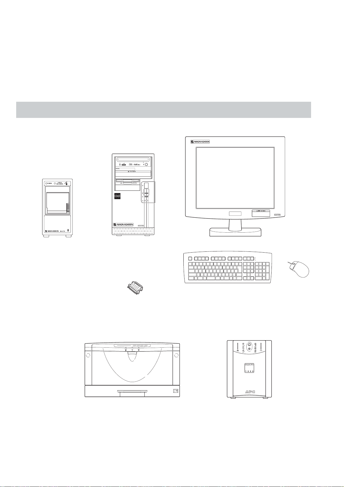
1. GENERAL
Use Nihon Kohden parts and accessories to assure maximum
performance from your instrument.
For simplicity, the suffix A/J/K will be omitted in this manual. There is no
difference in operation among models with different suffixes unless otherwise
specified.
Central Monitor Composition
NOTE
VL-971R/RK LCD Unit
WS-971R recorder unit
MU-971RA/RJ/RK
central monitor main unit
QP-971P/972P/973P/974P
program kit
Laser printer
(Network printer)
Keyboard
Mouse
UPS
Display selection:
Besides the VL-971R/RK LCD Unit, an LCD display recommended by Nihon
Kohden can also be used. For details, refer to the CNS-9701 installation guide.
1.2 Operator’s Manual CNS-9701
Page 27

1. GENERAL
Dual Display Monitoring Monitoring with dual displays is available. For example, with two displays
connected to one central monitor, you can display 16 patients, 8 patients on each
display, or you can set both displays to All Bed screen or one display to Expand
Individual Bed screen.
For the setting of the number of monitored beds or Expand Individual Bed screen,
refer to Section 4 “Monitor Setting”.
For the Windows settings necessary when using dual displays and connection
procedure, refer to the CNS-9701 installation guide.
Operator's Manual CNS-9701 1.3
Page 28
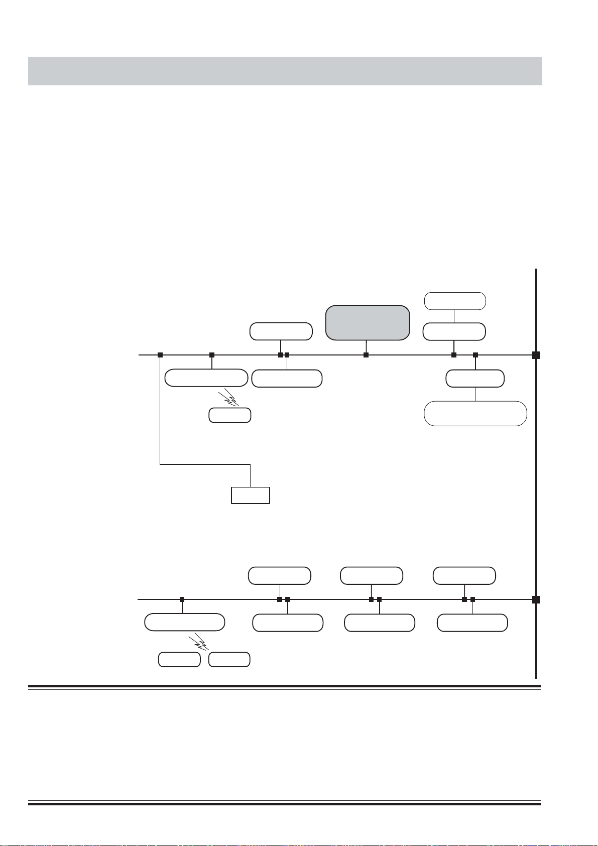
1. GENERAL
Network Composition
Network group
e.g. ICU
In a central monitor network, on a central monitor, you can see data of any bed in
the network. On a bedside monitor, you can see data of any bed in the network
using the interbed function.
The data that can be displayed on the bedside monitor or central monitor depends
on the type of bedside or central monitor used.
The number of central monitors and bedside monitors that can be connected to a
central monitor network and the method of network communication depend on the
type of monitor used. For details, refer to the Network and System installation
guide.
Central monitors
Bedside monitors
CNS-9300 series
Central monitor
Central monitor
CNS-9701
CNS-9300 series
Central monitor
Multiple patient receiver
ORG-9200
ORG-9700
Transmitter
Network group
e.g. CCU
Multiple patient receiver
Transmitter
Transmitter
Bedside monitor
BSM-9800
BSM-9510
BSM-4100 series
BSM-2300 series
BSM-1100 series
Bedside monitors/Transmitters
Printer
Central monitor
Bedside monitor
Central monitor
Bedside monitor
Interface
QI-910R
8000 series beds
Bedside monitors:
BSM-3101
BSM-7000 series
BSM-8000 series
Multiple patient receiver:
ORG-8200
Central monitor
Bedside monitor
WARNING
••
• Install the printer and hubs outside the patient environment (IEC 60601-1-1 2.204). If they are installed
••
inside the patient environment, the patient or operator may receive electrical shock.
••
• Check the software version number of the monitor before connecting it to the network. Different
••
software versions have different communication methods. When there is more than one communication
method in the network, communication may malfunction.
1.4 Operator’s Manual CNS-9701
Page 29
1. GENERAL
Operation Restriction by
Monitored Bed Type
Monitored Bed
BSS/BSM series
bedside monitor
ORG-9200/9700
multiple patient
receiver with
transmitter
BSM series bedside
monitor via QI-910R
interface
Type
What the central monitor can do depends on the monitored bed type.
Alarm function
Alarm Function
Temporarily
silence/suspend
alarms
Temporarily silence
any current alarms.
Temporarily suspend
all alarm functions
Turning alarm On/Off Priority
Not available
When all alarms are set
to OFF on the bedside
monitor, the alarm
function is OFF on the
central monitor.
Not available
Not available
When all alarms are set
to OFF on the bedside
monitor, the alarm
function is OFF on the
central monitor.
The alarm priority at
the central monitor
coincides with the
alarm priority at a
bedside monitor.
The alarm priority at
the central monitor
does not coincide with
the alarm priority at the
bedside monitor.
ST Recall window
Monitored Bed
Type
BSS/BSM series
bedside monitor
ORG-9200/9700
multiple patient
receiver with
transmitter
BSM series bedside
monitor via QI-910R
interface
Parameter Setup/Personal Setup/Setup
Monitored Bed
Type
BSS/BSM series
bedside monitor
ORG-9200/9700
multiple patient
receiver with
transmitter
BSM series bedside
monitor via QI-910R
interface
ST Recall File
Save Contents of the file
Date and time when the data was saved
Saved at set intervals.
(You can set the interval.)
Not available Not available
Alarm settings Other settings
The settings at the bedside
monitor and central
monitor are synchronized.
Changing one changes the
other.
Can be set on the central
monitor
The settings at the bedside
monitor and central
monitor are synchronized.
Changing one changes the
other.
•
Heart rate when the data was saved
•
Maximum 12 lead ST waveform
•
(Averaging 15 seconds ECG waveform)
Personal Setup
Some of the setting items that can be set on
the bedside monitor can also be set on the
central monitor.
All setting items can be set on the central
monitor.
Some of the setting items that can be set on
the bedside monitor can also be set on the
central monitor.
Operator's Manual CNS-9701 1.5
Page 30

1. GENERAL
NOTE
BSM in the table includes bedside monitors that receive or display data
from a transmitter connected to the patient.
Operation Restriction
Depending on Whether
Data Is Stored in the
Central Monitor
When registering a patient as a monitored bed, you need to select whether or not
the patient’s data is saved in the central monitor. Some operations are not available
on beds whose data is not saved in the central monitor.
Operations only available when data is saved in the central monitor
Admit/Discharge window
Channel window Setting a receiving channel
Full disclosure window Selecting saved waveforms
Arrythmia recall window Deleting a recall file
ECG 12 Lead Analysis window Deleting analysis result files
Alarm History window Displaying the list of all alarms
Report window Automatic report recording
Recording
* You can enter and edit patient data for an admitted bed whose data is not saved in
the central monitor.
Admit*
•
Discharge/Data deletion
•
Temporary discharge
•
Patient transfer
•
Remote recording requested from
bedside monitors
Monitored Bed
A monitored bed is a bed which is registered on the Monitor Setting window of the
System Setup and is continuously monitored at the central monitor.
1.6 Operator’s Manual CNS-9701
Page 31

Expand Individual Bed Screen
You can monitor with dual displays and set both displays to All Bed screen or one
display to Expand Individual Bed screen.
This setting is at “Expand Individual Bed screen” at “Display Setting” in “Monitor
Setting” of the System Setup screen.
1. GENERAL
Specific Functions of Expand Individual Bed screen
You can operate the Expand Individual Bed screen the same as the All Beds screen/
Individual Bed screen except for the following differences.
Display/Screen Items Regular Screen
Basic Information area
Review W i ndow
Expand Indiv. Bed
Number of waveform
traces
Number of numeric data 11 data max 13 data max
--- Available Not available
Trend
Tabular Trend Number of parameters 18 rows max 30 rows max
List
Recall
ST Recall Number of leads 3 leads max 6 leads max
Full Disclosure Time length on the
ECG 12 Lead
Analysis
Alarm History Number of alarms 15 alarms max 25 alarms max
Number of parameters 4 parameters max
Number of events 2 events max 6 events max
Number of parameters 17 rows max 26 rows maxHemodynamics
Blood pressure S/D/M Display in one row Display in each row
Number of
arrhythmia recall files
Number of expanded
arrhythmia recall
waveforms
compressed waveform
display
Display types Switch to display
Printing Differs depending on the display type.
8 traces max 11 traces maxIndividual Bed Screen Wave Display
(2 frames)
11 files max 18 files maxArrhythmia
1 file max Single waveform display:
12 min max 30 min max
Tabular Trend/
Zoom In Display/
Comparison Display/
Analysis Report.
Screen
6 parameter max
(3 frames)
3 files max
Multiple waveform
display:
1 file max
Tabular Trend/
Analysis Report are
regularly displayed.
Switch to display
Zoom in Display/
Comparison Display.
Operator's Manual CNS-9701 1.7
Page 32

1. GENERAL
Types of Windows
All Beds screen
4 patients (2 waveforms)
8 patients (2 waveforms)
6 patients (2 waveforms)
12 patients (2 waveforms)
16 patients (1 waveform)
1.8 Operator’s Manual CNS-9701
Page 33

Overview Bed Menu window Menu window
Individual Bed screen
1. GENERAL
Wave Display window
ECG 12 Lead Display window
All Vital Sign window
Operator's Manual CNS-9701 1.9
Page 34

1. GENERAL
Review windows
Report window
Full Disclosure window ST Recall window
ECG 12 Lead Analysis window
Arrhythmia Recall window
Trend window
1.10 Operator’s Manual CNS-9701
Tabular Trend window
Alarm History window
Page 35

System Setup Setup
1. GENERAL
Personal Setup
Parameter Setup
Operator's Manual CNS-9701 1.11
Page 36

1. GENERAL
Basic Operation
Control and Input
The operation of the central monitor is controlled through the touchscreen, mouse,
and keyboard.
• When using the VL-971R/RK LCD Unit, you can use the touchscreen function.
You can also use the optional keyboard and mouse.
• When using a Nihon Kohden recommended LCD display, operate with the
keyboard and mouse.
This manual explains operations assuming that the touchscreen function is used.
Touchscreen Input
When using the VL-971R/RK LCD Unit, you can operate the central monitor
through the touchscreen. To operate, directly touch an area of the screen with your
finger. In this manual, directly touching the XX key on the screen with your finger
is referred to as “Touch ‘XX’.”.
Example: Touch “REC”.
On any screen where text entry is required, you can use the on-screen keyboard as
you would an actual keyboard.
Keyboard Input
From the keyboard, you can input letters and numbers. You can also select an item
and scroll data with the arrow keys on the keyboard. In this manual, pressing the
XX key on the keyboard is referred to as “Press the XX key”.
Mouse Input
Mouse input is also available throughout the screens. Click items and menus on the
screen to select them. This technique has basically the same effect on screen
operations as the touchscreen input.
NOTE
The right mouse button has no function.
1.12 Operator’s Manual CNS-9701
Page 37

1. GENERAL
Switching Windows
Opening other windows from the Menu screen
To display the Menu screen, touch “Menu”. The Menu screen has all keys to open
all windows.
Returning to the All Beds screen
Touch “All Beds” on the bottom right of the screen.
Returning to the previous screen
Touch “Back”. Every time you touch this key you can return to the previous screen
until you select another bed.
Opening the Individual Bed screen from the All Beds screen
Touch the wave area of the patient you want to display the Individual Bed screen
for.
Changing the bed to display or change settings
Touch the basic information area of the patient you want to choose.
Operator's Manual CNS-9701 1.13
Page 38

1. GENERAL
Opening other windows with tabs
On the Individual Bed screen, windows of the Parameter Setup, Personal Setup and
Setup, you can switch the window types by touching the tab of the window name
you want to open.
Opening other windows with function keys
When the window is registered in the customized keys, you can also open the
window with the function keys.
Function keys
1.14 Operator’s Manual CNS-9701
Page 39

1. GENERAL
Changing Settings
Touch the setting on the screen. This can select and unselect and display the setting
window for the item.
Touch to change selection/non-selection.
According to the touched key, the corresponding setting list appears.
Scrolling Data and List
Touch “NONE” to
unselect all items.
Touch arrow keys to scroll data up and down or left and right. You can also scroll
with the arrow keys on the keyboard.
Operator's Manual CNS-9701 1.15
Page 40

1. GENERAL
Entering Letters and
Numbers
Enter letters and numbers from the keyboard on the screen.
You can also increase or decrease a setting value by touching “ ” or “ ” on the
screen.
Basic Keyboard Operation
1.16 Operator’s Manual CNS-9701
When the touch function keyboard is displayed on the screen, you can also input
letters and numbers from the keyboard. You can also scroll data with the arrow
keys on the keyboard.
Page 41

Caution Label and Caution Mark
Central Monitor Main Unit
1. GENERAL
CAUTION
Follow the specified procedure to turn off
the central monitor. Otherwise, patient data
will be deleted and data in the hard disk and
the hard disk itself may be damaged.
CAUTION
While the central monitor is on, do not touch unused
sockets. F ailure to follow this caution may damage the
monitor by static electricity and may cause
malfunction.
WARNINGs and
CAUTIONs about all
sockets on the rear panel
Refer to Section 3.
-240
VL-971R/RK LCD Unit
WARNING
Do not turn off the display to which the sound cable
is connected. Otherwise there is no alarm sound.
Operator's Manual CNS-9701 1.17
WARNINGs and CAUTIONs about all
sockets on the rear panel
Refer to Section 3.
Page 42

1. GENERAL
Important Safety Information
General
••
• Never use the central monitor in the presence of any flammable
••
anesthetic gas, concentrated o xygen or hyperbaric oxygen. Failure
to follow this warning may result in e x plosion.
••
• Never use the central monitor in a high-pressure oxygen medical
••
care tank. Failure to follow this warning may cause explosion or fire.
••
• Do not install any software other than specified by Nihon Kohden
••
and run it in the central monitor. Otherwise Nihon Kohden does not
warrant normal operation of the CNS-9701 system program.
••
• Do not install the CNS-9701 system software into a personal
••
computer which is not specified by Nihon Kohden and use it for
monitoring.
- If the personal computer does not satisfy the performance
specifications which are required by Nihon K ohden, the system
software may not function normally.
- If the personal computer does not satisfy the safety standards
which are required by Nihon Kohden, the patient and operator may
get electrical shock through another instrument in the network.
••
• While the central monitor is on, do not insert any CD-ROM or floppy
••
disk into it. Nihon Kohden does not warrant the normal operation of
the central monitor in the case that an application or software
installation starts automatically.
WARNING
CAUTION
••
• If any liquid might have gotten into the central monitor, take it out of
••
service and contact your Nihon Kohden distrib utor or
representatives.
••
• While the central monitor is on, do not touch unused sockets.
••
Failure to follow this caution may damage the monitor by static
electricity and may cause malfunction.
1.18 Operator’s Manual CNS-9701
Page 43

Installation
1. GENERAL
WARNING
Install the central monitor and external instruments outside the
patient environment (IEC 60601-1-1 2.204). If they are installed inside
the patient environment, the patient or operator may receive
electrical shock. For installation, contact your Nihon Kohden
distributor or representative.
CAUTION
••
• Only use the provided power cord. Using other power cords may
••
result in electrical shock or other injury to the patient and operator.
••
• Before connecting or disconnecting instruments, turn each
••
instrument off and disconnect each power cord from the AC socket.
Failure to follow this caution may cause electrical shock.
••
• Connect only the specified instruments to the central monitor by
••
following the specified procedure. Otherwise, electrical leakage
current may harm the patient and operator.
••
• Do not let connection cables stick out; run them along the floor or
••
wall. If people trip over the cable, the monitor may tip over and it
may cause injury.
UPS
WARNING
••
• Install the UPS outside the patient environment (IEC 60601-1-1 2.204).
••
If it is installed inside the patient envir onment, the safety standards
which are required by Nihon Kohden are not satisfied and it may
cause electrical shock to the patient or operator .
••
• Use a UPS which satisfies the safety standards specified by IEC and
••
UL. Otherwise, lack of safety may cause electrical shock to the
patient or operator.
••
• Periodically check the life of the UPS battery. Replace the battery
••
when the lifetime expires. If the battery is used be yond its lifetime,
liquid leakage, smoke, fire or explosion may occur.
CAUTION
••
• Make sure that the UPS is properly grounded. Otherwise the
••
operator may receive electrical shock.
••
• To assure an uninterrupted power suppl y, we recommend using the
••
specified UPS. A sudden loss of power supply or an extreme power
surge can damage the central monitor and delete stored data.
Operator's Manual CNS-9701 1.19
Page 44

1. GENERAL
Network
WARNING
••
• Connect the central monitor to the network as specified in the
••
Network and System Installation Guide. Otherwise the patient and
operator may get electrical shock or other injury. For connecting the
network, contact your Nihon Kohden distributor or representatives.
••
• Check the software version number of the monitor before connecting
••
it to the network. Different software versions have different
communication methods. When there is more than one
communication method in the network, communication may
malfunction.
••
• Install the external instruments including the printer and hubs
••
outside the patient environment (IEC 60601-1-1 2.204). If they are
installed inside the patient envir onment, the patient or operator may
receive electrical shock. For installation, contact your Nihon Kohden
distributor or representatives.
CAUTION
••
• Network settings and Windows 2000 system settings must only be
••
set by a qualified service personnel. Contact your Nihon Kohden
distributor or representatives.
••
• The network must be managed by the network administrator. Make
••
sure that each monitor in the network has a different IP address.
Otherwise, data communication cannot be performed properly and it
causes incorrect monitoring. When adding a monitor to an already
operating network, set the IP address on the monitor before
connecting the monitor to the network.
1.20 Operator’s Manual CNS-9701
Page 45

Turning the Power On/Off
1. GENERAL
WARNING
••
• Do not turn off the display to which the sound cable is connected.
••
Otherwise there is no alarm sound.
••
• When monitoring with two displays, do not turn off either display.
••
Otherwise some monitored beds cannot be monitored.
CAUTION
••
• Follow the specified procedure to turn off the central monitor.
••
Otherwise, patient data will be deleted and data in the hard disk and
the hard disk itself may be damaged.
••
• After turning the power on, confirm that there is a test sound from
••
the built-in speaker of the display.
Discharge and Receiving
Channel Change
WARNING
••
• Check that the channel number of the appropriate transmitter is
••
displayed on the central monitor screen. Otherwise data of a
different patient will be monitored or no signal will be received by the
central monitor.
••
• Do not use the same channel for different patients. Otherwise tw o
••
patients’ data will be lost due to mutual modulation interference or
another patient’s data may appear on the monitor screen.
CAUTION
••
• When admitting a new patient, first delete all data of the previous
••
patient. Otherwise, the data of the previous patient and new patient
will be mixed together and cause misunderstanding of the patient
history.
••
• When you change the receiving channel to monitor a new patient,
••
first delete all data of the previous patient. Otherwise, the data of the
previous patient and new patient will be mixed together and cause
misunderstanding of the patient history.
Operator's Manual CNS-9701 1.21
Page 46

1. GENERAL
Temporary Discharge
Patient T ransfer
WARNING
When a temporarily discharged patient comes back, resume
monitoring for the patient. During temporary discharge, there is no
display of measurement values, alarm function and data saving.
CAUTION
••
• Keep the original bedside monitor and the destination bedside
••
monitor power on and connected to the network until the transfer
completes. Otherwise transfer fails and the data is lost. After
transfer, confirm that the data was correctly transferred to the
destination bedside monitor.
••
• When the patient is transferred more than once between different
••
central monitors in the network, the data saved on the original
central monitor is deleted.
Alarm
WARNING
••
• Do not adjust the sound volume at the display unit. If you decrease
••
the display unit volume to the minimum, there is no alarm sound.
••
• When the Alarm Suspend key on the transmitter is pressed, all alarm
••
functions for the patient are suspended.
••
• Even if the alarm is set to ON, there is no arrhythmia alarm when
••
arrhythmia analysis is turned OFF at the bedside monitor and/or
central monitor.
••
• Before you start monitoring a new patient, confirm alarm settings.
••
Alarm settings return to Alarm Master 1 settings when a bed is
discharged or a receiving channel is changed.
••
• Securely connect the sound cable. There is no sound if the cable
••
comes off.
CAUTION
••
• When the upper or lower alarm limit is set to OFF, there will be no
••
upper or lower alarm for that limit. When it is set to OFF, frequently
observe the patient.
••
• Alarm does not occur for an arrhythmia whose alarm is set to OFF.
••
There is no indication that the alarm is set to OFF. Be careful when
you set the alarm to OFF.
1.22 Operator’s Manual CNS-9701
Page 47

ECG Monitoring
1. GENERAL
CAUTION
••
• If there is any doubt about the arrhythmia analysis, make the central
••
monitor relearn the patient’s VPC. Otherwise, an important
arrhythmia may be o verlooked.
••
• The central monitor does not perform ECG analysis. Therefore, the
••
QRS sound at the central monitor may not synchronize with patient’s
actual QRS when complicated arrhythmias occur or during pacing.
••
• The ST level transmitted from a transmitter is not designed to be
••
accurate enough for diagnosis. Do not rely on the ST level displayed
on the central monitor.
••
• The QRS sound at the central monitor has a delay of approximately
••
several seconds because of network connection.
••
• When the full disclosure waveform is expanded to actual size, it may
••
be distorted because it has been compressed then expanded. When
reading the expanded ECG waveforms, be aware of this distortion.
••
• Turn the pacing detection to ON when monitoring a pacemaker
••
patient. Otherwise QRS and pacemaker spike may not be
distinguished and pacemaker failure may not be recognized.
NIBP Measurement
WARNING
••
• When performing long term measurements at intervals less than 2.5
••
minutes, periodicall y check the state of the patient, blood vessels
and limb for adequate circulation. Congestion may occur at the
measurement site.
••
• When performing periodic measurements for a long term,
••
periodically check the circulation condition.
CAUTION
Before you remotely start and stop NIBP measurement from the central
monitor, confirm the state of the patient at the bedside monitor.
Carefully start and stop NIBP measurement from the central monitor.
Operator's Manual CNS-9701 1.23
Page 48

1. GENERAL
Maintenance
CAUTION
••
• Before maintenance (inspection, cleaning, disinfection), turn the
••
central monitor power off and disconnect the power cord from the
AC outlet. Otherwise the operator may receive electrical shock or the
central monitor may malfunction.
••
• Do not disassemble or repair the central monitor. Disassembly and
••
repair must be performed b y qualified service personnel.
••
• Software upgrade must only be done by qualified service personnel
••
or a person with technical knowledge. If upgrade is not done
correctly, the central monitor may freeze.
••
• Do the regular inspection according to the cycle specified by Nihon
••
Kohden. Otherwise, deterioration and loss of function are
overlooked and it results in incorrect monitoring.
••
• Restart the central monitor once every three months. Otherwise the
••
operation becomes unstable and monitoring may stop. During
restarting, patients monitored by the central monitor must be
monitored by another instrument.
••
• Replace the hard disk once every two years. If the hard disk gets
••
damaged, monitoring is incorrect and all data saved in the central
monitor is lost.
For the VL-971R/RK LCD unit
••
• Follow your hospital regulations to handle blood or bodily fluids on
••
the display.
••
• Be careful not to let any liquid get inside the display.
••
1.24 Operator’s Manual CNS-9701
Page 49

Section 2 P anel Description
Central Monitor Main Unit MU-971RA/RJ/RK .................................................................... 2.1
Front Panel .............................................................................................................. 2.1
Rear Panel............................................................................................................... 2.2
LCD Unit VL-971R/RK ....................................................................................................... 2.3
Front ........................................................................................................................ 2.3
Rear......................................................................................................................... 2.3
LCD Unit (Locally Purchased Recommended Display)...................................................... 2.4
Recorder Unit WS-971R .................................................................................................... 2.5
Laser Printer (Network Printer) .......................................................................................... 2.5
UPS ................................................................................................................................... 2.6
Operator's Manual CNS-9701 2C.1
Page 50

Central Monitor Main Unit MU-971RA/RJ/RK
WARNING
While the central monitor is on, do not insert any CD-ROM or floppy
disk into it. Nihon Kohden does not warrant the normal operation of
the central monitor in the case that an application or software
installation starts automatically .
CAUTION
While the central monitor is on, do not touch unused sockets.
Failure to follow this caution may damage the monitor by static
electricity and may cause malfunction.
2. PANEL DESCRIPTION
Front Panel
Power switch
Turns main unit on or off when the main power switch on the rear
panel is on ( ).
Power switch cover
For attaching, refer to CNS-9701 installation guide.
Power lamp
Lights when the power is on.
Hard disk lamp
Lights when the hard disk is being accessed.
Reset switch
Normally not used.
Operator's Manual CNS-9701 2.1
Page 51

2. PANEL DESCRIPTION
Rear Panel
AC SOURCE socket
Main power switch
KEYBOARD socket
MOUSE socket
NETWORK socket
RS-232C socket
NOTE
••
• Do not remove the covers from the unused sockets on the rear panel
••
of the central monitor main unit.
••
• Do not touch the sockets on the rear panel of the main unit or cables
••
around the sockets. Otherwise, static electricity may cause
malfunction of the monitor.
-240
PROTECT KEY socket
RECORDER socket
SOUND socket
Name Description
AC SOURCE socket Connects to a UPS via the power cord provided with the central monitor
Main power switch Turns on or off to supply power to the main unit. Under normal
KEYBOARD socket Connects to the keyboard.
MOUSE socket Connects to the mouse.
NETWORK socket Connects to network system via a network cable.
RS-232C socket Connects an instrument to receive or send serial data.
SOUND socket Connects to the SOUND socket on the display.
PROTECT KEY socket Connects to the blue protection key (standard accessory of the central
RECORDER socket Connects to the WS-971R recorder unit via the recorder cable provided
VIDEO1/VIDEO2 socket Connects to the VIDEO socket on the LCD unit via the RGB connection
TOUCH 1/TOUCH 2 socket Connects to the TOUCHSCREEN socket on the LCD unit via the
VIDEO1/VIDEO2 socket
TOUCH 1/TOUCH 2 socket
main unit.
conditions keep this switch turned on ( ).
monitor main unit) via the connection cable (standard accessory of the
central monitor main unit). You must connect the blue protection key to
start the system. When using optional QP-971P/972P/973P/974P
program kits, connect white protection keys for the program kits to the
blue protection key.
with the central monitor main unit.
cable provided with the VL-971R/RK LCD unit.
touchscreen connection cable provided with the VL-971R/RK LCD unit.
2.2 Operator’s Manual CNS-9701
Page 52

LCD Unit VL-971R/RK
2. PANEL DESCRIPTION
WARNING
Do not turn off the display to which the sound cable is connected.
Otherwise alarm sound does not occur.
Front
Touchscreen display
Rear
DC IN socket
Connects to the AC adapter cord.
AC adapter (100 to 240V)
Connects to a UPS via the power
cord provided with the VL-971R/
RK LCD unit.
Menu/Select
Up/Right
Operator's Manual CNS-9701 2.3
M
Video Source
S
Down/Left
SOUND socket
Connects to the SOUND socket on the
central monitor main unit via the sound
cable provided with the central monitor.
Power switch
Turns on ( ) or off ( ) the LCD
unit. Under normal conditions
keep this switch turned on.
TOUCHSCREEN socket
Connects to the TOUCH 1/TOUCH 2 socket on
the central monitor main unit via the touchscreen
connection cable provided with the LCD unit.
VIDEO socket
Connects to the VIDEO1/VIDEO2 socket on the
central monitor main unit via the RGB connection
cable provided with the LCD unit.
Page 53

2. PANEL DESCRIPTION
LCD Unit (Locally Purchased Recommended Display)
WARNING
••
• Do not turn off the display to which the sound cable is connected.
••
Otherwise alarm sound does not occur.
••
• Do not adjust the sound volume at the display unit. If you decrease
••
the volume to the minimum, there is no alarm sound.
For the specifications that Nihon Kohden recommends, refer to “Local Purchase
Units” in Section 1. Read the display manual together.
Recommended LCD display: NANAO FlexScan L565
The recommended model may be changed without notice. Contact your Nihon
Kohden distributor or representative when you locally purchase a display.
2.4 Operator’s Manual CNS-9701
Page 54

Recorder Unit WS-971R
POWER lamp
Lights when the power is on.
CHECK RECORDER lamp
Lights when communication
between the recorder unit and
central monitor is disconnected
or when there is abnormality in
the recorder unit.
2. PANEL DESCRIPTION
Fuse holder
Two fuses (1A) are contained.
Fuse must be replaced by
qualified service personnel.
Power switch
Turns the power ON ( ) or OFF
( ).
Usually, keep the power ON.
Paper magazine release lever
Press to open the magazine.
Paper magazine
Contains the recording paper.
Laser Printer (Network Printer)
Power socket
Connects to a UPS with a power
cord provided with the central
monitor main unit and supplies
power (100 to 240V) to the
recorder unit.
PC socket
Connects to the RECORDER socket on the
rear panel of the central monitor main unit
with the recorder cable provided with the
central monitor main unit.
Use the laser printer that Nihon Kohden recommends. Connect to the network
when you use the network printer. Refer to the printer manual together.
Recommended laser printer: Hewlett Packard, LaserJet 4100n
Hewlett Packard, LaserJet 4200n
The recommended model may be changed without notice. Contact your Nihon
Kohden distributor or representative when you locally purchase a laser printer.
Operator's Manual CNS-9701 2.5
Page 55

2. PANEL DESCRIPTION
UPS
WARNING
••
• Periodically check the lifetime of the UPS battery. Replace the
••
battery when the lifetime expires. If the battery is used beyond its
lifetime, liquid leakage, smoke, fire or explosion may occur.
••
• Make sure that the UPS is properly grounded. Otherwise the
••
operator may receive electrical shock.
Recommended UPS: American Power Conversion, Smart UPS
CNS-9701A/J SUA1000
CNS-9701K SUA1000I
The recommended model may be changed without notice. Contact your Nihon
Kohden distributor or representative when you locally purchase a UPS.
Read the UPS manual together.
We recommend using the specified UPS. However, if the recommended UPS
cannot be acquired, use a UPS which satisfies the following specifications.
• It has an equipotential grounding terminal.
• The output wave is a sine wave. (When the output wave is a square wave, the AC
voltage may become lower due to the AC filter.)
• Inverter type. (With a switch type, noise may interfere when the power changes
from AC to battery.)
• An alarm sound is generated at the power failure and the alarm cannot be turned
off.
2.6 Operator’s Manual CNS-9701
Page 56

Section 3 Preparation
Installation Conditions........................................................................................................ 3.1
Connecting the Monitor to Other Instruments and Systems .............................................. 3.2
Connecting the Monitor to Other Instruments.......................................................... 3.2
Standard Instruments .................................................................................... 3.2
Optional Instruments ..................................................................................... 3.2
Using a UPS (Uninterruptable Po wer Supply) ......................................................... 3.2
Connecting to a Network System ............................................................................ 3.3
Operation Flowchart .......................................................................................................... 3.4
Loading the Recording Paper ............................................................................................ 3.5
Loading Paper in the WS-971R Recorder Unit ........................................................ 3.5
Loading Paper in the Laser Printer .......................................................................... 3.6
Turning Power On/Off ........................................................................................................ 3.7
Preparation Before Power On .................................................................................. 3.7
Turning the Displa y and Main Unit Power On .......................................................... 3.7
Starting the Central Monitor System.............................................................. 3.8
Turning the Power Off .............................................................................................. 3.8
Turning the WS-971R Recorder Unit Power On....................................................... 3.9
Preparation After Turning the Power On .......................................................................... 3.10
Changing Settings on the System Setup Screen................................................... 3.10
Before Starting Monitoring ..................................................................................... 3.11
Check Before Use............................................................................................................ 3.12
Check Before Turning On the Monitor.................................................................... 3.12
Check After Turning On the Monitor and During Monitoring .................................. 3.12
Operator's Manual CNS-9701 3C.1
Page 57

Installation Conditions
Install the monitor where the screen can be seen clearly and does not reflect light.
••
• Do not install the monitor where it will be exposed to water or
••
••
• Avoid exposing the monitor to direct sunlight. Otherwise, the
••
••
• Avoid locations where the monitor may receive strong
••
••
• Make sure that there is enough space between the monitor and the
••
••
• Do not place blankets or cloth over the monitor. It may affect
••
••
• Do not install the monitor in a dusty area.
••
••
• Connect the power cord to an AC outlet which can supply sufficient
••
••
• When there is any problem with the monitor, turn off the power
••
3. PREPARATION
WARNING
Install the central monitor and external instruments outside the
patient environment (IEC 60601-1-1 2.204). If they are installed inside
the patient environment, the patient or operator may receive
electrical shock. For installation, contact your Nihon Kohden
distributor or representative.
CAUTION
chemical solutions. Avoid direct sprinkling, spra y or moist air from
the nebulizer or humidifier. These cause malfunction and shorten the
life of the monitor .
temperature rises and it causes malfunction and shortens the life of
the monitor.
electromagnetic interference such as radio or TV stations, cellular
phone or mobile two-way radios.
wall for adequate ventilation. Otherwise the internal temperature of
the monitor rises, which leads to inaccurate operation and shortens
the monitor life.
- Leave more than 5 cm of space between the wall and vent holes on
the sides and rear panels of the monitor.
- When the monitor is surrounded, leave more than 10 cm of space
above the monitor for ventilation. Do not let the surrounding
temperature exceed 35°C during operation.
monitoring.
AC current to the monitor. The monitor cannot function properly with
low current. Also the breaker trips and it causes electric po wer
failure.
immediately and disconnect the power cord from the AC outlet. Take
the monitor out of service and check for damage.
Operator's Manual CNS-9701 3.1
Page 58

3. PREPARATION
Connecting the Monitor to Other Instruments and Systems
WARNING
••
• Connect only the specified instruments to this monitor by following
••
the specified procedure. Otherwise, electrical leakage current may
harm the patient and operator.
••
• Before connecting or disconnecting instruments, make sure that the
••
power of each instrument is turned off. Failure to follow this warning
may cause electrical shock.
NOTE
For the procedure, refer to the installation guide.
Connecting the Monitor to
Other Instruments
Using a UPS
(Uninterruptable Power
Supply)
Standard instruments
• Central monitor main unit MU-971RA/RJ/RK
• LCD unit VL-971R/RK or Nihon Kohden specified LCD display
• Keyboard, mouse
Optional instruments
• Recorder unit WS-971R
• Laser printer (Nihon Kohden specified printer)
• UPS (Nihon Kohden specified UPS)
WARNING
Use a UPS which satisfies the safety standards specified by IEC and
UL. Otherwise, lack of safety may cause electrical shock to the patient
or operator.
CAUTION
••
• Make sure that the UPS is properly grounded. Otherwise the
••
operator may receive electrical shock.
••
• To assure an uninterrupted power suppl y, we recommend using the
••
specified UPS. A sudden loss of power supply or an extreme power
surge can damage the central monitor and delete stored data.
Do not exceed the capacity of the UPS. Otherwise, the system program will crash
at electric power failure and it damages the central monitor.
At electric power failure, immediately shut down the central monitor system with
the normal procedure. After the backup period of the UPS, data may be lost or the
instrument may get damaged.
3.2 Operator’s Manual CNS-9701
Page 59

3. PREPARATION
Connecting to a Network
System
For the procedure, refer to the CNS-9701 installation guide. The connection
method and grounding method depends on the location where the central monitor
is installed and the types and installation locations of other instruments.
Refer to the reference “General Requirements for Connecting Medical Electrical
System” in Section 15. Follow IEC 60601-1-1.
WARNING
••
• Connect the central monitor to the network as specified in the
••
Network and System Installation Guide. Otherwise patient and
operator may get electrical shock or other injury. For connecting the
network, contact your Nihon Kohden distributor.
••
• Do not use a damaged network cable. Otherwise patient or operator
••
may get an electrical shock when the damaged part is touched.
••
• Connect only the specified instruments to the connector or sockets
••
marked with by following the specified procedure. Otherwise,
electrical leakage current may harm the patient and operator.
CAUTION
Before connecting instruments, make sure that the power is turned off.
Operator's Manual CNS-9701 3.3
Page 60

3. PREPARATION
Operation Flowchart
CAUTION
Network settings and Windows 2000 system settings must only be set
by qualified service personnel. Contact your Nihon Kohden distributor
or representative.
NOTE
••
• Contact your Nihon Kohden distributor or representative for system
••
connection. System connection and system setup settings must be
managed by a system administrator in your hospital.
••
• The system does not start without the blue protection key (standard
••
accessory of the central monitor main unit) connected to the
PROTECT KEY socket on the rear panel.
For system connection and procedure before turning the power on, refer to the
installation guide.
This section explains turning the central monitor power on/off, preparation at the
central monitor after turning the power on and setting recording paper.
1. Connect the blue protection key (standard accessory of the central monitor
main unit) to the PROTECT KEY socket via the connection cable (standard
accessory of the central monitor main unit). Refer to the CNS-9701
installation guide for details.
2. Connecting the central monitor to other instruments
Refer to the installation guide.
Connect the central monitor main unit to the LCD display, recorder unit. Load
the recording paper.
3. Connecting the central monitor to the network
Refer to the installation guide.
4. Turning the central monitor power on
Refer to the installation guide.
Turn on the power of the central monitor and other instruments on the system.
5. Setting the system setup settings
Set the necessary system setup settings. Refer to Section 4.
6. Admitting patients/Entering patient information/Starting monitoring
7. Setting for each bed (Parameter Setup, Personal Setup, Setup)
8. Starting monitoring.
3.4 Operator’s Manual CNS-9701
Page 61

Loading the Recording P aper
Loading Paper in the WS971R Recorder Unit
••
• Do not allow paper to contact pastes, adhesive agents, oil-based felt
••
pen tips or diazo process (ditto/spirit) copying paper. These discolor
the paper surface.
••
• Do not allow paper to contact any materials containing vinyl chloride,
••
plastic eraser, adhesive tape, fluorescent felt tip pen, or cinnabar seal
ink because these discolor the recorded waveforms and data.
••
• Do not apply strong pressure to the paper. Rubbing or scratching
••
discolors the paper surface.
••
• Do not allow paper to contact saline solution. The paper discolors
••
and if the saline solution gets on the thermal head, there will be dots
missing from the recorded data.
••
• Avoid high humidity, high temperature, direct sunlight and direct
••
fluorescent light when storing recording paper. Otherwise the paper
may discolor. Store the recording paper in a dry, cool place.
••
• When using glue on the recording paper, only use glue which
••
consists of starch, polyvinyl alcohol, gum arabic, or carboxymethyl.
3. PREPARATION
CAUTION for Handling the Recording Paper
CAUTION for Loading the Recording Paper
••
• Correctly load the recording paper as specified. Otherwise,
••
recording may not be performed properly .
••
• Do not touch the recording head with any hard material. When the
••
head is tapped with hard material, the head may crack and the heater
element wire may short-circuit.
••
• Clean the head surface with the provided head cleaner pen before
••
loading new paper. After a period of usage, paper dust may
accumulate between the paper and the head surface, and good
printing cannot be obtained.
NOTE
Only use the specified recording paper, FQW50-3-100.
Operator's Manual CNS-9701 3.5
Page 62

3. PREPARATION
1. Push up the paper magazine release lever to open the paper magazine.
magazine release lever
2. Open the paper magazine.
detection mark
3. Set the recording paper (FQW50-3-100) inside the magazine so that the
detection mark (small black square on corner) of the paper is on the right side.
4. Draw out one page of paper toward you and close the paper magazine.
5. Touch “REC” on the All Beds screen to confirm that recording starts. Then
touch “REC” again to confirm that recording stops.
Loading Paper in the Laser
Refer to the printer manual.
Printer
3.6 Operator’s Manual CNS-9701
Page 63

Turning Power On/Off
3. PREPARATION
Preparation Before Power
On
Turning the Display and
Main Unit Po wer On
Confirm that the system connection is properly done. Refer to the installation
guide. Load the recording paper in the recorder and printer. Prepare other
instruments on the system.
1. Press the power switch on the display unit to turn the power on ( ).
NOTE
••
• When using the VL-971R/RK LCD unit, turn the LCD unit power on
••
before turning the central monitor main unit power on. Otherwise the
touch screen does not function.
••
• When using the recommended LCD display, refer to the display
••
manual.
Power switch
Power switch
2. Press the main power switch on the rear panel of the main unit to turn on the
main power ( ). The power lamp lights.
Main power switch
-240
3. Slide the power switch cover on the front panel of the main unit and press the
power switch to turn the power on. The power lamp lights. After the system
check finishes, there is a test sound from the built-in speaker of the display.
CAUTION
After the power on, confirm that there is a test sound from the built-in
speaker of the display.
The All Beds screen appears.
Power lamp
Operator's Manual CNS-9701 3.7
Page 64

3. PREPARATION
NOTE
••
• If the power lamp does not light, confirm the power cord connection.
••
The lamp does not light when the specified power is not supplied to
the instrument.
••
• It takes a few minutes for the LCD screen to reach full brightness.
••
••
• The shadow of the previous screen may remain for a few minutes
••
after changing screens.
••
• There may be some dots on the LCD screen which are always on or
••
always off, but it does not affect monitoring. This is normal for all
LCD screens.
Starting the central monitor system
The system starts automatically when the central monitor main unit is turned on.
To restart the system when Windows 2000 is running and the system has been shut
down at least once before, double-click the “CNS9701.exe” icon on the desktop.
Turning the Power Off
CAUTION
The central monitor power must be turned off in the specified order.
Otherwise, patient data will be deleted and other data in the hard disk
or the central monitor may be damaged.
NOTE
When the patient is transferred from one central monitor to the other,
the data before the patient transfer is stored on the first central
monitor. If this first central monitor power is turned off, the data before
the patient transfer cannot be displayed on the second central monitor.
1. Shut down the central monitor system
(1) Touch “System Setup”. The Revision window of the System Setup opens.
(2) Touch “System Exit”. The confirmation window appears.
(3) Touch “Yes” to shut down the system.
2. Shut down Windows 2000.
Touch “Start” to select “Shut Down”. Select “Shut Down” and click “OK”
when the confirmation window appears.
3.8 Operator’s Manual CNS-9701
Page 65

3. PREPARATION
3. Turn the display power off.
Press the power switch on the display to turn the display power off ( ).
Power switch
4. Turn the other instruments power off.
NOTE
Leave the power of the UPS and multiple patient receiver on.
Turning the WS-971R
Recorder Unit Power On
Press the power switch on the rear panel to turn the recorder power on ( ). Check
that the POWER lamp lights and the CHECK RECORDER lamp is off.
Power switch
Lamp lit
Lamp not lit
Operator's Manual CNS-9701 3.9
Page 66

3. PREPARATION
Preparation After Turning the P o wer On
Changing Settings on the
System Setup Screen
Set necessary settings on the System Setup screen. On the System Setup screen,
you can set settings that affect the system.
Setting window Setting items
Sound Control Alarm sound volume, QRS sound settings (on/off,
tone, QRS bed, volume)
Recording Recording time (for manual recording, periodic
recording, alarm/call recording, darkness)
Touchscreen Settin g Calibrate touchscreen
System Configuration System Configuration settings (Units, Cover sheet for
report recording, ECG 12 lead printing format,
admission settings, Telemetry silence time, Vital sign
alarm off mark, Screen timeout, Old NIBP display,
NIBP effective time, All beds patient name display
size), RS-232C setups
Monitor Setting Display setting, Monitored beds setting , Bed name
setting
ORG Setting Settings for the ORG-9200/9700 multiple patient
receiver
Mouse Setting Settings for the mouse
Parameters Select parameters which aren’t currently measured to
be displayed on setting keys
Name Registration Editing and selecting CNS group name, editing and
saving the message displayed during temporary
discharge
Parameter Colors Display color for each parameter
Alarm Master Editing alarm masters
Function Keys Assigning functions to function keys
Date & Time Setting date and time displayed on the scr een
NOTE
Changing this setting affects the entire network.
Maintenance
Confirming network, changing the password to access
some windows of the System Setup.
NOTE
The shaded settings need a password to access. These settings can
only be entered or changed by operators who have the authority and
password.
3.10 Operator’s Manual CNS-9701
Page 67

3. PREPARATION
Before Starting Monitoring Before starting monitoring of a patient, do the following preparation.
WARNING
Before you start monitoring a new patient, confirm alarm settings.
When monitoring via ORG-9200/9700 multiple patient receiver, the
alarm settings return to the Alarm Master 1 settings when a bed is
discharged or data is deleted.
1. Admit a patient
When you monitor a patient via a telemetry system, set the receiving channel.
2. Confirm alarm settings.
3. Set the setting for the bed (as needed)
• recording settings
• channel settings
• other settings
4. Checking the receiving condition of the telemetry system.
Press the Call button on the transmitter to confirm that the signal from the
transmitter is correctly received at the central monitor.
5. Prepare the patient for measurement (electrode attachment and connection)
Refer to the operator’s manual of bedside monitors.
Operator's Manual CNS-9701 3.11
Page 68

3. PREPARATION
Check Before Use
Check the following items before turning on the monitor. If any problem is
detected, take the proper countermeasure according to the troubleshooting and
maintenance sections. If there is any damage or the instrument is suspected to be
faulty as a result of checking, attach an “Unusable” or “Repair request” label to the
instrument and contact your Nihon Kohden distributor or representative.
Check Before Turning On
the Monitor
• Enough electrodes and electrode leads are ready.
• Enough recording paper is in the recorder.
• Cleaned and sterilized sensors and transducers are ready.
• The blue protection key (standard accessory of the central monitor main unit)
and protection keys for the optional QP-971P/972P/973P/974P program kits
are securely connected.
• Power cord is connected properly.
• Equipotential grounding lead is connected properly when equipotential
grounding is required.
• The system is connected properly.
• All cables for measurement are connected properly.
• The channel setting at the central monitor matches the transmitter channel.
• The transmitter battery is not weak.
• No scratches, damage or dirt on the monitor, sensors and electrodes.
• No damage to the keys, switch, lamps and panels.
• No damage to the power cord.
• No damage or dirt to the electrode leads, transducers, probes and cables.
• The monitor is not in a wet place.
• The transmitter has the battery cover.
Do not use anything sharp to touch the LCD screen (touchscreen), power switches
and other keys. Otherwise it may damage the instrument.
Check After T urning On the
Monitor and During
Monitoring
3.12 Operator’s Manual CNS-9701
To start monitoring safely and properly, check the following items after turning on
the monitor. If any problem is detected, take the proper countermeasure according
to the troubleshooting and maintenance sections.
• The power lamp lights.
• There is no fire, smoke or smell.
• A bong sounds when the central monitor system program starts.
• The monitor is not too hot. The monitor does not give an electric shock when
touched.
• No error message is displayed on the screen.
• The time on the screen is correct.
• The low battery mark for the transmitter does not appear on the transmitter
LCD display.
• The monitor does not affect surrounding equipment.
Page 69

3. PREPARATION
• The data and waveforms are displayed properly.
• The touch keys function properly. (when using the display with touchscreen
function)
• Keys and switch operate properly.
• The keyboard and mouse operate properly.
• Alarm functions properly.
• When the CALL button on the transmitter is pressed within the specified range
of the central monitor, a message appears on the central monitor screen.
• There is no trouble in recording.
• No error display and malfunction during operation.
• Other instruments on the system operate normally.
CAUTION
After turning the power on, confirm that a bong sounds from the builtin speaker of the display.
NOTE
After turning the monitor on and when admitting a patient on the
monitor, make sure that the time displayed at the upper right of the
screen is correct. The clock may gain or lose time during operation.
When the date or time is changed during monitoring, the date and time
of all stored data is also changed and may not match the date and time
on the printout.
Operator's Manual CNS-9701 3.13
Page 70

Section 4 System Setup Screen
Overview of the System Setup Screen .............................................................................. 4.1
Displaying the System Setup Screen....................................................................... 4.2
Sound Control.................................................................................................................... 4.3
Setting Alarm Sound Volume ................................................................................... 4.3
Setting QRS Sound ................................................................................................. 4.4
Turning the QRS Sound ON/OFF .................................................................. 4.4
Changing the QRS Tone ................................................................................ 4.4
Setting the QRS Bed ..................................................................................... 4.4
Setting QRS Sound Volume ..................................................................................... 4.4
Recording .......................................................................................................................... 4.5
Touchscreen ...................................................................................................................... 4.5
System Configuration Settings........................................................................................... 4.6
Changing Values on the System Configuration Window .......................................... 4.6
Changing Unit Settings ............................................................................................ 4.7
Temperature Unit ........................................................................................... 4.7
Height Unit..................................................................................................... 4.7
Weight Unit .................................................................................................... 4.7
Pressure Unit................................................................................................. 4.7
Changing Recording/Printing Settings ..................................................................... 4.7
Report Cover Sheet....................................................................................... 4.7
ECG 12 Lead Printing Format ....................................................................... 4.7
Changing Admitting/Discharging Settings................................................................ 4.8
Discharge Mode ............................................................................................ 4.8
Auto Resume After P ause ............................................................................. 4.8
Alarm Settings ......................................................................................................... 4.8
Telemetry Silence Time ................................................................................. 4.8
Turning Vital Sign Alarm Off Mark Display ON/OFF ...................................... 4.8
Screen Settings ....................................................................................................... 4.8
Setting Screen Timeout ................................................................................. 4.8
Old NIBP Display Setting............................................................................... 4.8
NIBP Effective Time Setting........................................................................... 4.9
All Beds Patient Name Displa y Siz e .............................................................. 4.9
RS-232C Settings .................................................................................................... 4.9
Monitor Settings............................................................................................................... 4.10
Displaying the Monitor Setting Windo w.................................................................. 4.10
Operator's Manual CNS-9701 4C.1
Page 71

Registering Monitored Beds .................................................................................. 4.11
Data Storage ............................................................................................... 4.12
Setting Bed Name Setting...................................................................................... 4.12
Setting Display Setting........................................................................................... 4.13
Changing the Number of Displays ............................................................... 4.13
Expand Individual Bed Screen..................................................................... 4.13
Changing the Number of Patients Displayed on the Main Display and the
Second Display............................................................................................ 4.13
Setting the All Beds Numeric Area .............................................................. 4.14
ORG Settings................................................................................................................... 4.15
Mouse Settings ................................................................................................................ 4.16
Displaying the Mouse Setting Window................................................................... 4.16
Moving the Mouse to Another Display Unit............................................................ 4.17
Selecting the Mouse Position................................................................................. 4.18
Selecting the Central Monitor Where Mouse Can Operate.................................... 4.18
Parameters ......................................................................................................................4.20
Group Name and Temporary Discharge Message Settings ............................................. 4.21
Displaying the Name Registration Window ............................................................ 4.21
Setting the Group................................................................................................... 4.22
Editing Group Names ............................................................................................ 4.22
Editing the Message on Temporarily Discharged Beds.......................................... 4.23
Setting the Parameter Colors........................................................................................... 4.24
Setting the Alarm Master ................................................................................................. 4.25
Setting Function Keys ...................................................................................................... 4.25
Setting Date & Time......................................................................................................... 4.26
Maintenance .................................................................................................................... 4.28
Confirming Instruments Connected on the Network .............................................. 4.28
Changing the Pass w ord......................................................................................... 4.29
Enabling/Disabling Screen Hard Copy Printing...................................................... 4.30
4C.2 Operator's Manual CNS-9701
Page 72

Overview of the System Setup Screen
On the System Setup screen, you can set settings that affect the system.
Setting window Setting items
Sound Control Alarm sound volume, QRS sound settings (on/off,
tone, QRS bed, volume)
Recording Recording time (for manual recording, periodic
recording, alarm/call recording, darkness)
Touchscreen Setting Calibrate touchscreen
System Configuration System Configuration settings (Units, Cover sheet for
report recording, ECG 12 lead printing format,
admission settings, Telemetry silence time, Vital sign
alarm off mark, Screen timeout, Old NIBP display,
NIBP effective time, All beds patient name display
size), RS-232C setups
Monitor Setting Display setting, Monitored beds setting, Bed name
setting
ORG Setting Settings for the ORG-9200/9700 multiple patient
receiver
Mouse Setting Settings for the mouse
Parameters Select parameters which aren’t currently measured to
be displayed on setting keys
Name Registration Editing and selecting CNS group name, editing and
saving the message displayed during temporary
discharge
Parameter Colors Display color for each parameter
Alarm Master Editing alarm masters
Function Keys Assigning functions to function keys
Date & Time Setting date and time displayed on the screen
Changing this setting affects the entire network.
Maintenance
Confirming network, changing the password to access
some windows of the System Setup.
4. SYSTEM SETUP SCREEN
NOTE
NOTE
The shaded settings need a password to access. These settings can
only be entered or changed by operators who have the authority and
password.
Operator's Manual CNS-9701 4.1
Page 73

4. SYSTEM SETUP SCREEN
Displaying the System
Setup Screen
Touch to open another window
Central monitor
information
Monitored bed information
Touch “System Setup” to display the System Setup screen.
Enter the password
Touch to shut down
the system
4.2 Operator’s Manual CNS-9701
Page 74

Sound Control
4. SYSTEM SETUP SCREEN
Set alarm sound volume, QRS sound on/off, QRS tone, QRS bed and QRS sound
volume.
1. Touch “System Setup” to display the System Setup screen.
2. Touch “Sound Control” to display the Sound Control window.
Setting Alarm Sound
Volume
The volume can be set in seven steps.
NOTE
There is an alarm sound even when set to the minimum step level.
WARNING
Do not adjust the sound volume at the display unit. If you decrease the
display unit volume to the minimum, there is no alarm sound.
Touch “ ” or “ ” to increase or decrease the volume. To check, there is a
sound of the selected level every time you touch “ ” or “ ”. You can also
change the volume by directly touching the bar.
Operator's Manual CNS-9701 4.3
Page 75

4. SYSTEM SETUP SCREEN
Setting QRS Sound
CAUTION
••
• The central monitor does not perform ECG analysis. Therefore, the
••
QRS sound at the central monitor may not synchronize with patient’s
actual QRS when complicated arrhythmias occur or during pacing.
••
• The QRS sound at the central monitor has a delay of approximately
••
several seconds because of network connection.
Turning the QRS Sound ON/OFF
Set the QRS sound on or off. Touch “ON” or “OFF” in “QRS Sound”.
Changing the QRS Tone
Set the QRS tone. Touch “High” or “Low” in “QRS Tone”.
Setting the QRS Bed
Select the bed of the QRS sound source. For the bed selected as the QRS Bed, the
QRS sync mark ( ) appears on the All Beds screen, Individual Bed screen and
basic information area.
Touch a desired key in “QRS Bed”.
Current Bed: QRS sound source is a currently selected bed.
(Specific Bed Name): QRS sound source is always the specific bed.
The setting procedure is the same as setting alarm sound volume.Setting QRS Sound Volume
4.4 Operator’s Manual CNS-9701
Page 76

Recording
4. SYSTEM SETUP SCREEN
Refer to Section 10.
Touchscreen
Refer to Section 14.
Operator's Manual CNS-9701 4.5
Page 77

4. SYSTEM SETUP SCREEN
System Configuration Settings
On the System Configuration window, you can set system settings of the central
monitor.
Changing Values on the
System Configuration
window
1. Touch “System Setup” to display the System Setup screen.
2. Enter the password.
The password is displayed
as ****.
3. Touch “System Configuration” to display the System Configuration window.
4. Touch the key for the item you want to change. The setting window opens.
5. Touch the key for the desired value.
6. Touch “ ” to set the entry.
4.6 Operator’s Manual CNS-9701
Page 78

4. SYSTEM SETUP SCREEN
Changing Unit Settings
Changing Recording/
Printing Settings
NOTE
Changing units affects the entire network. A changed value takes
effect at the moment “Yes” is touched on the confirmation window.
Temperature Unit
Celsius/Fahrenheit
Height Unit
cm/inch
Weight Unit
kg/lb
Pressure Unit
mmHg/kPa
Report Cover Sheet
Select whether or not to print the cover sheet in report printing. Select ON or OFF
at “Report Cover Sheet”.
The following information is printed on the cover sheet.
• Patient information
• Date and time of report creation
• Report creation conditions
• Comment (Nurse Notes)
• ECG waveform (5-second waveforms 5 minutes before the end time of printing
data)
ECG 12 Lead Printing Format
Select printing format (number of leads × number of traces) of the all ECG
waveforms (maximum 12 leads) display on the ECG 12 Lead Display window of
the Individual Bed screen and the Overview Bed screen.
Selectable formats: 6rows × 2cols, 12rows × 1cols, 3rows × 4cols
Operator's Manual CNS-9701 4.7
Page 79

4. SYSTEM SETUP SCREEN
Changing Admitting/
Discharging Settings
Alarm Settings
Discharge Mode
There are two modes for discharging mode.
• Discharge mode: When “Discharge” is touched, all patient data is deleted, the
bed becomes “Off”, and monitoring ends. To restart
monitoring, do the admitting operation.
• Delete Data mode: When “Delete Data” is touched, all patient data is deleted,
the bed does not become “Off”, and monitoring continues.
Auto Resume After Pause
When the pause period is set, you restart monitoring patient at the bedside monitor
(transmitter) and monitoring continues for as long as the pause period, the
temporary discharge automatically releases and monitoring resumes at the central
monitor. The factory default pause period is 3 min.
When OFF is selected, monitoring at the central monitor does not resume until
“Resume” is touched on the Admit/Discharge window.
Selectable values: OFF, 10 sec, 30 sec, 1 min, 2 min, 3 min
Telemetry Silence Time
This setting is for beds connected via the ORG-9200/9700 multiple patient receiver.
Set the alarm silence time when the Silence Alarms key ( ) is touched.
Selectable values: 1 min, 2 min, 3 min, 4 min, 5 min, 10 min
Screen Settings
Turning Vital Sign Alarm Off Mark Display ON/OFF
Set whether or not the vital sign alarm off mark is displayed.
ON: Displays the vital sign alarm off mark depending on the setup of the bedside
monitor.
OFF: Does not display the vital sign alarm off mark.
Setting Screen Timeout
When any screen other than the All Beds screen is displayed and there is no
operation for a preset period, the screen automatically returns to the All Beds
screen. Enter the period with the numerical pad keys on the screen and touch
“ENTER” to fix the entry.
Selectable values: OFF, 1 to 30 min
Old NIBP Display Setting
Select whether to dim or hide the old data.
• Dim: NIBP measurement is dimmed.
• Hide: NIBP measurement deleted and “---” displayed.
4.8 Operator’s Manual CNS-9701
Page 80

4. SYSTEM SETUP SCREEN
NIBP Effective Time Setting
Select how long to wait after NIBP measurement to dim or hide NIBP.
Selectable values: 10 min, 30 min, 1h, 24h
All Beds Patient Name Display Size
You can select the size of the patient’s name display on the All Beds screen.
• normal
• large
RS-232C Settings
1. Touch “RS-232C Setup” to display the setting window.
2. Set the necessary settings.
The factory default settings are underlined.
• Baud Rate: 2400, 4800, 9600, 14400, 19200, 38400
• Data Bits: 7, 8
• Parity: None, Even, Odd
• Stop Bits: 1, 1.5, 2
• Flow Control: None, XON/XOFF, Hardware, Hardware XON/XOFF
• Communication Mode: NK Protocol, Off
Operator's Manual CNS-9701 4.9
Page 81

4. SYSTEM SETUP SCREEN
Monitor Settings
NOTE
The Monitor settings can only be set by an operator who has the
authority and password.
There are three categories of monitor setting.
• Monitored Beds Setting
• Bed Name Setting
• Display Setting
Displaying the Monitor
Setting Window
The password is displayed
as ****.
1. Touch “System Setup” to display the System Setup screen.
2. Enter the password.
3. Touch “Monitor Setting”. The Monitor Setting window opens.
4.10 Operator’s Manual CNS-9701
Page 82

4. SYSTEM SETUP SCREEN
Registering Monitored
Beds
Red: Beds whose data is saved in this central monitor
Blue: Beds whose data is saved in another central monitor
You can register monitored beds from up to 300 beds on the network. Monitored
beds are the beds that are continuously monitored at the central monitor. When you
register a monitored bed, you need to select whether or not to save the bed’s data at
the central monitor.
1. Touch “Monitored Beds Setting”. The setting window opens.
2. Touch the frame of the display position you want to change the bed for. The
layout of display positions on this screen corresponds to the layout on the All
Beds screen.
3. Touch the bed to be monitored in “Select Monitored Beds”.
A window to confirm data storage for the bed opens. When the bed’s data is
saved at another central monitor, this window does not open.
NOTE
••
• If you try to register a bed to a position where another bed is already
••
registered, a dialog box asks if you want to delete other bed’s
registration (stop monitoring the bed). Touch “Yes” to delete the
other bed’s registration and all saved data for the bed. Touch “No” to
keep the other bed’s registration and cancel registration of a new
bed.
••
• If you register a previously registered bed to the position of another
••
bed, the positions of the two beds are switched.
Operator's Manual CNS-9701 4.11
Page 83

4. SYSTEM SETUP SCREEN
4. Touch “Yes” or “No” to select whether or not to save the bed’s data at this
central monitor.
Data Storage
Availability of settings and operations depends on whether or not the bed’s data is
saved in this central monitor or another central monitor.
Beds whose data is saved in this central monitor (Red):
This central monitor is the main central monitor for the bed. Review data such as
full disclosure waveform and recall files are saved in this central monitor. All
settings and operations are available at this central monitor.
Beds whose data is saved in another central monitor (Blue):
This central monitor is not the main central monitor for the bed. For review data
such as full disclosure waveform and recall files, this central monitor refers to
another central monitor that saves the bed’s data. This central monitor cannot set
the settings for data storage such as admitting/discharging, patient transfer, stored
waveform setting, etc.
Setting Bed Name Setting
NOTE
••
• Data for a bed can only be saved in one central monitor.
••
••
• If a bed’s data is not saved in any central monitor, the bed’s review
••
data cannot be displayed on any central monitor. Be sure to save a
bed’s data in one of the central monitors on the network.
NOTE
Do not use the same bed name for more than one bed in a group.
1. Touch “Bed Name Setting” to display the setting window.
2. Touch the key of the desired bed.
3. Enter the bed name from the keyboard on the screen. You can enter any name
of up to 8 or 10 alphanumeric characters.
4. Touch “ENTER” to register the setting.
4.12 Operator’s Manual CNS-9701
Page 84

4. SYSTEM SETUP SCREEN
Setting Display Setting Touch “Display Setting” to display the setting window.
Changing the Number of Displays
Select the number of displays to be connected to the central monitor.
Select either Single Display or Dual Display at “Number of Displays”.
To select “Dual Display”, you need to enable VIDEO 2 output on Windows 2000 in
advance. Only VIDEO 1 is enabled at the factory default setting.
Expand Individual Bed Screen
You can monitor with dual displays and set both displays to All Beds screen or one
display to Expand Individual Bed screen.
To set this, select one of the followings on the Expand Indiv. Display of the
Monitor Settings.
• OFF: Both displays show the All Beds screen and the Individual Bed
screen.
• Main Display: The Main Display shows the Expand Individual Bed screen
and the Second Display shows the All Beds screen.
• Second Display: The Second Display shows the Expand Individual Bed screen
and the Main Display shows the All Beds screen.
When you change the setup of the Individual Bed screen, a window to confirm the
shutdown of the system appears. Touch “OK” to go back to the windows screen.
Double click “CNS9701.exe” to start the central monitor program. The Expand
Individual Bed screen is displayed.
Changing the Number of Patients Display ed on the Main Display and
Second Display
Set the number of patients to be displayed on the All Beds screen.
When you use dual displays, set for each display.
Selectable values: 16 Patients (1 Wave), 12 Patients (2 Wave), 8 Patients (2
Wave), 6 Patients (2 Wave), 4 Patients (2 Wave)
NOTE
You cannot select fewer patients than are registered to monitored
beds.
Operator's Manual CNS-9701 4.13
Page 85

4. SYSTEM SETUP SCREEN
Setting the All Beds Numeric Area
Set the size of the numeric area on the All Beds screen.
The size of the numeric values changes to fit with the numeric area.
• normal:
• large:
4.14 Operator’s Manual CNS-9701
Page 86

ORG Settings
4. SYSTEM SETUP SCREEN
NOTE
The ORG settings can only be set by an operator who has the authority
and password.
Set the settings for the ORG-9200/9700 multiple patient receiver. This setting can
only be set at the central monitor that is monitoring beds via the ORG-9200/9700
multiple patient receiver.
1. Touch “System Setup” to display the System Setup screen.
2. Enter the password.
The password is displayed
as ****.
3. Touch “ORG Setting”. The ORG Setting window opens.
4. Touch the key for the desired ORG. Set the necessary settings.
Touch the key of the ORG for which you want to
change settings. The ORG name is its serial number.
ORG you are currently
changing the settings for.
Set the name of the group
the ORG belongs to.
Set the channel band the
ORG belongs to.
Select the antenna type.
Select the transmitter type,
A or C, for each bed.
Select either normal mode or RSSI mode (radio signal strength indicator) for each
bed. In RSSI mode, the radio field strength of each bed is shown as a number from
0 to 15 (the larger the number, the stronger the radio field strength).
Operator's Manual CNS-9701 4.15
Page 87

4. SYSTEM SETUP SCREEN
Mouse Settings
Up to six displays can be operated by one mouse. This includes other central
monitors and dual displays. The mouse settings are set at the central monitor
where the mouse is connected.
NOTE
When you want to operate CNS-9701 and CNS-9300 series central
monitors with one mouse, connect the mouse to the CNS-9701 central
monitor.
Displaying the Mouse
Setting Window
The password is displayed
as ****.
1. Touch “System Setup” to display the System Setup screen.
2. Enter the password.
3. Touch “Mouse Setting”. The Mouse Setting window opens.
In general, these six display positions correspond to the physical locations of
the actual display units. “Primary Mouse Controller” indicates the display
position of the first display unit of this physical monitor. If this monitor has a
dual display, “Secondary Mouse Controller” indicates its display position.
4.16 Operator’s Manual CNS-9701
Page 88

4. SYSTEM SETUP SCREEN
Moving the Mouse to
Another Display Unit
The password is displayed
as ****.
1. Touch “System Setup” to display the System Setup screen.
2. Enter the password.
3. Touch “Mouse Setting”. The Mouse Setting window opens.
If a display position is dim, the mouse cannot move there.
4. If the mouse is not on this physical display unit, touch “Find Cursor”. The
mouse cursor moves to this central monitor display unit.
5. In the six display positions, move the mouse up, down, left or right toward the
display position of the display unit you want to operate the mouse on.
Operator's Manual CNS-9701 4.17
Page 89

4. SYSTEM SETUP SCREEN
Selecting the Mouse
Position
Select the central monitor where the mouse is connected.
1. Touch “Mouse Controller”.
2. Touch the position of the central monitor that the mouse is connected to.
In dual display mode, the second display (Secondary Mouse Controller) is
automatically set to the right of the first display (Primary Mouse Controller).
Selecting the Central
Monitor Where Mouse Can
Operate
Set the central monitors where the mouse can operate. Up to six central monitors
can be selected.
1. Touch “Applicable Displays”. The selectable central monitors are displayed in
“Available Central Monitors”.
2. To select the desired central monitors,
(1) Touch the key of the position to change the mouse control settings for.
4.18 Operator’s Manual CNS-9701
Page 90

4. SYSTEM SETUP SCREEN
(2) In “Available Central Monitors”, touch the desired central monitor. Or,
touch “Stop Monitoring” to select no central monitor for the selected
position.
(3) A setting window for the selected central monitor opens. (The setting
window does not open when the selected central monitor is the CNS-9300
series central monitor.) Set the settings for the central monitor.
Display type:
Select either single display or
dual display
(4) Touch “ ” to close the window and register the setting.
Dual display layout type:
When using in dual display mode,
select whether the central monitor
is placed vertically or horizontally.
Operator's Manual CNS-9701 4.19
Page 91

4. SYSTEM SETUP SCREEN
Parameters
The password is displayed
as ****.
You can select parameters which aren’t currently measured to be displayed on the
keys on the screen. The selected parameters appear on setting keys even when the
parameter is not measured.
1. Touch “System Setup” to display the System Setup screen.
2. Enter the password.
3. Touch “Parameters”. The Parameters window opens.
Every touch of a key toggles between selected and unselected.
Every touch of this key toggles between
“select all” and “select nothing”
4.20 Operator’s Manual CNS-9701
Page 92

4. SYSTEM SETUP SCREEN
Group Name and Temporary Discharge Message Settings
The name of a central monitor is set on
Windows 2000. Refer to the CNS-9701
installation guide.
Displaying the Name
Registration Window
The password is displayed
as ****.
On the Name Registration window, set the following settings.
• Set Group Name
• Edit Group Names
• Edit Pause Location Names
1. Touch “System Setup” to display the System Setup screen.
2. Enter the password.
Touch to open another
setting window.
3. Touch “Name Registration”. The Name Registration window opens.
Operator's Manual CNS-9701 4.21
Page 93

4. SYSTEM SETUP SCREEN
Setting the Group
Set the location (group) on the network where the central monitor is installed. The
factory default setting is “General”.
1. On the Name Registration window, touch “Set Group Name”. The setting
window opens.
2. Touch the key for the desired group.
Editing Group Names
NOTE
This settings can only be set by an operator who has the authority and
password.
Edit group names of up to 8 alphanumeric characters. Group names are shared in
the entire network. Up to 16 names can be saved.
1. On the Name Registration window, touch “Edit Group Names”. The setting
window opens.
2. Touch the key for the group you want to change the name for and then enter
the desired name from the keyboard on the screen.
3. Touch “ENTER” to save the setting.
4.22 Operator’s Manual CNS-9701
Page 94

4. SYSTEM SETUP SCREEN
Editing the Message on
Temporarily Discharged
Beds
You can edit the message displayed on temporarily discharged beds. Up to 12
messages can be saved.
1. On the Name Registration window, touch “Edit Pause Location Names”. The
setting window opens.
2. Touch the key you want to edit the message for.
3. Enter the message from the keyboard on the screen.
4. Touch “ENTER” to save the setting.
Operator's Manual CNS-9701 4.23
Page 95

4. SYSTEM SETUP SCREEN
Setting the Parameter Color s
You can set the color for each parameter.
1. Touch “System Setup” to display the System Setup screen.
2. Enter the password.
The password is displayed
as ****.
3. Touch “Parameter Colors”. The Parameter Colors window opens.
4. Touch the key of the parameter you want to change the color for. You can
confirm the color displayed on the window next to the key.
5. Touch the key of the desired color in “Parameter Colors”.
Press “Return to Default Color” to return the color of the currently selected
parameter to the factory default setting.
4.24 Operator’s Manual CNS-9701
Page 96

Setting the Alarm Master
Refer to Section 6.
Setting Function Keys
There are five free function keys on the bottom of the screen. For quick operation,
it is convenient to assign frequently used functions and windows to the function
keys.
1. Touch “System Setup” to display the System Setup screen.
2. Enter the password.
4. SYSTEM SETUP SCREEN
The password is displayed
as ****.
3. Touch “Function Keys”. The Function Keys window opens.
4. Touch the tab of a function key you want to assign a function or window to.
The setting window opens.
5. Touch the key of the desired function or window.
Operator's Manual CNS-9701 4.25
Page 97

4. SYSTEM SETUP SCREEN
Setting Date & Time
Set the date and time displayed at the upper right of the screen.
NOTE
Changing the date and time affects the entire network.
1. Touch “System Setup” to display the System Setup screen.
2. Enter the password.
The password is displayed
as ****.
3. Touch “Date & Time”. The Date & Time window opens.
4. Touch the item you want to set (Year, Month, Day, Hour, Minute). A keyboard
appears on the screen.
5. Enter the desired value and then touch “ENTER”. A message window to
confirm the change appears. Repeat this step for other items.
4.26 Operator’s Manual CNS-9701
Page 98

4. SYSTEM SETUP SCREEN
6. After you set all date and time items, touch “Set”.
NOTE
If you change to another window or screen without touching “Set”,
the new value is lost.
7. Touch “Yes” to register the settings.
Operator's Manual CNS-9701 4.27
Page 99

4. SYSTEM SETUP SCREEN
Maintenance
On this window, you can confirm which instruments are connected on the network.
Instruments in the network whose power is turned on are displayed. Confirm the
number of instruments. You can also change the password to access some windows
of the System Setup.
Confirming Instruments
Connected on the Network
The password is displayed
as ****.
Instrument’s name
(bed name or CNS name)
1. Touch “System Setup” to display the System Setup screen.
2. Enter the password.
3. Touch “Maintenance”. The Maintenance window opens and network
information is displayed.
Group nameIP address
Touch to reload the latest information
Manual setting of a central monitor’s IP
address is done on Windows 2000. Refer
to the CNS-9701 installation guide.
4.28 Operator’s Manual CNS-9701
CNS-XXXX: Central monitor (system)
BSM-XXXX: Bedside monitor
Tele-9000: beds whose data is received via the ORG-9200/9700
multiple patient receiver or transmitter.
(An IP address in parenthesis is the address where the bed’s data is saved.)
Page 100

4. SYSTEM SETUP SCREEN
Changing the Password
To access some windows of the System Setup, you need a password. You can set a
password which consists of four numbers. The factory default setting is “1234”,
but we recommend that you change this password.
1. On the Maintenance window of the System Setup, touch “Password”. The
setting window opens.
2. In the “Enter new password” box, enter a new password with the keyboard on
the screen and touch “ENTER”.
3. Enter the password again in the “Verify new password” box and touch
“ENTER”.
Operator's Manual CNS-9701 4.29
 Loading...