

Page 1

Automated
Hematology Analyzer
MEK-6400/MEK-6410/MEK-6420
If you have any comments or suggestions
on this manual, please contact us at:
www.nihonkohden.com
MEK-6400C
MEK-6400J
MEK-6400K
MEK-6410C
MEK-6410J
MEK-6410K
MEK-6420C
MEK-6420J
MEK-6420K
0634-900086B
Page 2

CONTENTS
Contents
GENERAL HANDLING PRECAUTIONS ..............................................................................i
WARRANTY POLICY ......................................................................................................... ii
RESPONSIBILITIES – PROFESSIONAL USERS .............................................................ii
EMC Related Caution ........................................................................................................ iii
Conventions Used in this Manual and Instrument ............................................................. v
Warnings, Cautions and Notes ................................................................................ v
Section 1 General ................................................................................. 1.1
Introduction .................................................................................................................... 1.2
Service Policy ................................................................................................................ 1.3
Specifications ................................................................................................................ 1.4
Measured Parameters, Ranges and Reproducibility to Specimen from Venous
Blood .......................................................................................................... 1.4
Standardization Analysis Method ............................................................... 1.4
Detection Method ....................................................................................... 1.5
Dilution Ratio .............................................................................................. 1.5
Counting Time ............................................................................................ 1.5
Display ....................................................................................................... 1.5
Data Storage .............................................................................................. 1.5
Environmental Conditions ........................................................................... 1.5
Power Requirements .................................................................................. 1.5
Dimensions and Weight .............................................................................. 1.6
Electromagnetic Compatibility .................................................................... 1.6
Safety ........................................................................................................ 1.6
Panel Description ........................................................................................................... 1.7
Front Panel ........................................................................................................... 1.7
Right Side Panel................................................................................................... 1.8
Rear Panel ........................................................................................................... 1.9
Composition .................................................................................................................. 1.10
MEK-6400 ...........................................................................................................1.10
MEK-6410 ...........................................................................................................1.11
MEK-6420 ...........................................................................................................1.12
Interference Substances ............................................................................................... 1.13
Section 2 Troubleshooting .................................................................. 2.1
Check Procedure Flowchart ........................................................................................... 2.4
Operating Condition and Blood Sample Checks ............................................................. 2.5
Operating Condition Check ................................................................................... 2.5
Blood Sample Handling Check ............................................................................. 2.5
Pre-dilution Sample Preparation Check ................................................................ 2.5
Checking the Hematology Analyzer................................................................................ 2.7
Checking Background Noise ................................................................................ 2.7
Measurement ............................................................................................. 2.7
Service Manual MEK-6400/6410/6420 C.1
Page 3

CONTENTS
Parameter Data Check with Diluent ............................................................ 2.7
Reducing Background Noise ...................................................................... 2.8
Background Noise Problems ...................................................................... 2.9
Checking the Reproducibility ................................................................................ 2.9
Checking Procedure ................................................................................... 2.9
CV Values ................................................................................................. 2.10
Checking Accuracy ....................................................................................................... 2.11
Checking Procedure ............................................................................................ 2.11
Poor WBC Reproducibility ....................................................................................2.11
Poor HGB Reproducibility ....................................................................................2.12
Poor RBC Reproducibility .................................................................................... 2.13
Poor PLT Reproducibility .....................................................................................2.14
Poor HCT or MCV Reproducibility ....................................................................... 2.15
Solving Problems from Alarm Messages ...................................................................... 2.16
A001: No diluent ........................................................................................2.16
A005: No detergent ................................................................................... 2.16
A007: No lysing reagent ............................................................................ 2.17
A009: WBC priming error ........................................................................... 2.17
A010: RBC PRIMING ERROR ................................................................... 2.17
A021: WBC level 1 .................................................................................... 2.17
A022: WBC level 2 .................................................................................... 2.18
A023: WBC level 3 .................................................................................... 2.18
A024: WBC bubble 1 ................................................................................. 2.18
A025: WBC bubble 2 ................................................................................. 2.18
A026: WBC bubble 3 ................................................................................. 2.19
A027: WBC bubble 4 ................................................................................. 2.19
A029: WBC clog ........................................................................................ 2.19
A030: WBC sample error ........................................................................... 2.19
A031: WBC noise 2 ................................................................................... 2.20
A032: WBC noise 1 ................................................................................... 2.20
A036: WBC upper manometer dirty ........................................................... 2.20
A037: WBC lower manometer dirty ............................................................ 2.20
A041: RBC level 1 .....................................................................................2.21
A042: RBC level 2 .....................................................................................2.21
A043: RBC level 3 .....................................................................................2.21
A044: RBC bubble 1 .................................................................................. 2.22
A045: RBC bubble 2 .................................................................................. 2.22
A046: RBC bubble 3 .................................................................................. 2.22
A047: RBC bubble 4 .................................................................................. 2.22
A049: RBC clog......................................................................................... 2.22
A050: RBC sample error ............................................................................2.23
A051: RBC noise 2 .................................................................................... 2.23
A052: PLT noise 1 ..................................................................................... 2.23
A053: PLT noise 3 ..................................................................................... 2.23
A057: RBC upper manometer dirty ............................................................ 2.23
A058: RBC lower manometer dirty ............................................................ 2.23
A061: HGB voltage low .............................................................................2.24
A062: HGB voltage high ............................................................................ 2.24
A063: HGB circuit error .............................................................................2.24
C.2 Service Manual MEK-6400/6410/6420
Page 4

CONTENTS
A072: Tube holder open ............................................................................. 2.24
A073: Tube in the holder ............................................................................ 2.25
A091: Room temperature high ...................................................................2.25
A092: Room temperature low .................................................................... 2.25
A093: Internal temperature high ................................................................ 2.25
A094: Internal temperature low .................................................................. 2.25
A095: Power supply temp high ..................................................................2.25
! APPEARS ON THE RIGHT OF WBC MEASURED VALUE .................... 2.26
! APPEARS ON THE RIGHT OF MCHC MEASURED VALUE .................. 2.26
C APPEARS ON THE RIGHT OF WBC OR PLT MEASURED VALUE or
PLT Clumps appears ................................................................................. 2.27
OTHER FLAGS ......................................................................................... 2.27
Solving Problems from System Error Messages ........................................................... 2.28
E001: DILUTER INITIALIZE ERROR ........................................................ 2.28
E021: SAMPLER INITIALIZE ERROR ......................................................2.28
E041: SUB BATH INITIALIZE ERROR ...................................................... 2.28
E101: BATH DRAIN ERROR ..................................................................... 2.29
E122: CHECK SETTINGS ........................................................................ 2.29
E123: MEMORY ERROR .......................................................................... 2.29
E124: CIRCUIT ERROR ............................................................................ 2.29
E126: TOUCH PANEL ERROR .................................................................. 2.29
E141: CAP PIERCE INITIALIZE ERROR ................................................. 2.29
Service Maintenance Screens ....................................................................................... 2.30
Displaying the SERVICE Screen ......................................................................... 2.30
CHECK MENU Screen ........................................................................................ 2.32
UNIT MAINTE Screen ......................................................................................... 2.32
MD-640V ................................................................................................... 2.33
MS-640V ................................................................................................... 2.33
MS-641V (MEK-6400 only) ........................................................................2.34
MV & PUMP CHK ..................................................................................... 2.34
CONT MEASURE Screen ................................................................................... 2.35
SETTING MENU Screen .....................................................................................2.35
ADV. SETTINGS Screen ........................................................................... 2.35
REAGENT FACTOR Screen......................................................................2.36
USER MAINTENANCE Screen ................................................................. 2.36
PANIC VALUE Screen (for MEK-6400 and MEK-6410) .............................. 2.37
FLAG SETTINGS Screen ......................................................................... 2.37
BAR CODE PORT Screen ........................................................................ 2.37
UNIT CAL Screen ..................................................................................... 2.38
MONITOR Screen ............................................................................................... 2.38
X10-CV screen .................................................................................................... 2.39
INITIAL MENU Screen ........................................................................................2.40
OTHER MENU Screen ........................................................................................ 2.40
PRINT SETTINGS Screen .................................................................................. 2.40
Section 3 Board/Unit Description ....................................................... 3.1
Board and Unit Location ................................................................................................. 3.3
Right Side View .................................................................................................... 3.3
Service Manual MEK-6400/6410/6420 C.3
Page 5

CONTENTS
Left Side View ...................................................................................................... 3.3
Front View ............................................................................................................ 3.4
Top View ............................................................................................................... 3.4
MC-640V Measuring Unit ................................................................................................ 3.5
MD-640V Combination Syringe Pump Unit ..................................................................... 3.5
MP-640V Pump Unit ....................................................................................................... 3.6
PV-641V Front Panel Unit ............................................................................................... 3.6
JQ-640V Inlet/Outlet Unit ............................................................................................... 3.7
JQ-641V/JQ-642V Valve Unit ......................................................................................... 3.7
JQ-641V Valve Unit .............................................................................................. 3.7
JQ-642V Valve Unit .............................................................................................. 3.7
MS-640V Sampler Unit ................................................................................................... 3.8
MS-641V Cap Pierce Unit (MEK-6400 only) ................................................................... 3.8
MR-640V Rinse Unit (MEK-6410/6420 only) ................................................................... 3.9
UT-7192 AMP CONTROL Board ..................................................................................... 3.9
UT-7193 POWER Board ................................................................................................ 3.10
UT-7198 MEASURING Board ........................................................................................ 3.10
UT-7201 HGB AMP Board and UT-7202 HGB LED Board .............................................. 3.11
UT-7200 MIXED PUMP Board ....................................................................................... 3.11
UT-7205 PRINTER DRIVER Board ................................................................................ 3.12
UT-7203 KEY Board ...................................................................................................... 3.12
UT-7199 LIQUID SENSOR Board .................................................................................. 3.13
XP-602V/XP-612V 2-way Electromagentic Valve .......................................................... 3.13
Section 4 Disassembly and Assembly .............................................. 4.1
Before You Begin ............................................................................................................ 4.2
Warnings and Cautions ......................................................................................... 4.2
Required Tools ...................................................................................................... 4.2
Caution and Notes Related to Valve Joint, Black Screw and Tube Joint in the
Instrument ............................................................................................................ 4.3
Board and Unit Location ....................................................................................... 4.3
Turning the Power Off ..................................................................................................... 4.4
Cleaning and Draining the Fluid Pathway .............................................................. 4.4
Turning the Power Off ........................................................................................... 4.5
Removing the Right Side Cover, Top Cover and Rear Cover........................................... 4.6
Reattaching the Right Side Cover, Top Cover and Rear Cover ............................. 4.7
Removing the Front Panel Unit ....................................................................................... 4.8
Reattaching the Front Panel Unit .......................................................................... 4.9
Installing the WA-640VK Printer Unit (Option)................................................................4.10
Removing the Measuring Unit ....................................................................................... 4.12
Reattaching the Measuring Unit ..........................................................................4.13
Accessing the Connectors on the POWER Board .........................................................4.14
Reassembling the Board .....................................................................................4.14
Removing the Combination Syringe Pump Unit .............................................................4.15
Reattaching the Combination Syringe Pump Unit ................................................4.16
Removing the Pump Unit ............................................................................................... 4.17
Reattaching the Pump Unit ................................................................................. 4.18
Removing the Sampler Unit ........................................................................................... 4.19
C.4 Service Manual MEK-6400/6410/6420
Page 6

CONTENTS
Reattaching the Sampler Unit..............................................................................4.22
Removing the Cap Pierce Unit or Rinse Unit .................................................................4.23
Reattaching the Cap Pierce Unit or Rinse Unit .................................................... 4.24
Removing the Inlet/Outlet Unit ...................................................................................... 4.25
Reattaching the Inlet/Outlet Unit ......................................................................... 4.26
Removing the Valve Unit ............................................................................................... 4.26
Reattaching the Valve Unit .................................................................................. 4.27
Removing the AMP CONTROL Board ........................................................................... 4.28
Reattaching the AMP CONTROL Board .............................................................. 4.29
Removing the POWER Board ........................................................................................ 4.30
Reattaching the POWER Board ..........................................................................4.31
Removing the MEASURING Board ...............................................................................4.32
Reattaching the MEASURING Board .................................................................. 4.33
Removing the MIXED PUMP Board ..............................................................................4.34
Reattaching the MIXED PUMP Board .................................................................4.34
Removing the PRINTER DRIVER Board ....................................................................... 4.35
Reattaching the PRINTER DRIVER Board .......................................................... 4.35
Removing the KEY Board..............................................................................................4.36
Reattaching the KEY Board ................................................................................ 4.36
Removing the LIQUID SENSOR Board ......................................................................... 4.37
Reattaching the LIQUID SENSOR Board ............................................................ 4.37
Removing the LCD ........................................................................................................ 4.38
Reattaching the LCD ........................................................................................... 4.39
Removing the Transformer .............................................................................................4.40
Reattaching the Transformer ................................................................................ 4.40
Section 5 Adjustment........................................................................... 5.1
General ........................................................................................................................... 5.2
Adjusting the HGB Sensor Output Voltage ..................................................................... 5.3
Adjusting the Upper and Lower Sensor Output Voltages of the Manometers .................. 5.6
Adjusting the Liquid Sensor Output Voltages .................................................................. 5.9
Section 6 Maintenance ........................................................................ 6.1
General ........................................................................................................................... 6.3
Disposing of Waste............................................................................................... 6.4
Repair Parts Availability Policy ............................................................................. 6.4
Parts to be Replaced Periodically......................................................................... 6.4
Maintenance Schedule ................................................................................................... 6.5
Displaying Operation History Screen .............................................................................. 6.6
Maintenance Check Sheet ............................................................................................. 6.8
Before Maintenance Procedure ..................................................................................... 6.12
Strong Cleaning ...................................................................................................6.12
Draining Measurement Baths and Sub Baths ...................................................... 6.13
Turning Power Off ................................................................................................ 6.14
Daily Maintenance Procedures ......................................................................................6.15
Checking Reagents and Other Consumables ...................................................... 6.15
Checking the Appearance of the Analyzer .......................................................... 6.15
Service Manual MEK-6400/6410/6420 C.5
Page 7

CONTENTS
Disinfecting the Surface of the Analyzer ................................................... 6.16
Cleaning the Surface of the Analyzer ........................................................6.16
Checking the Reagents Connection Tubes .......................................................... 6.16
Checking the Power Cord and Grounding Lead....................................................6.16
Checking the External Instrument Connection ....................................................6.16
Checking the Power On ....................................................................................... 6.17
Calibrating the Touch Screen ..................................................................... 6.17
Checking the Date and Time ............................................................................... 6.17
Clock Accuracy.........................................................................................6.18
Measuring Background Noise..............................................................................6.18
Measuring Hematology Control ........................................................................... 6.20
Checking Measurement Baths and Sub Baths .................................................... 6.21
Checking Pump Tube........................................................................................... 6.21
Weekly/Every 300 Counts Maintenance Procedures ..................................................... 6.21
Checking/Cleaning Filters ................................................................................... 6.21
Monthly/Every 1,000 Counts Maintenance Procedures ................................................. 6.22
Replacing Filters ................................................................................................. 6.22
Materials Required ....................................................................................6.22
Procedure ................................................................................................. 6.22
Checking and Cleaning Measurement Baths and Sub Baths ............................... 6.23
Materials Required ....................................................................................6.23
Procedure ................................................................................................. 6.24
Checking and Cleaning/Replacing the Rinse Unit and Cap Pierce Nozzle ...........6.26
Materials Required ....................................................................................6.26
Procedure ................................................................................................. 6.27
Every Four Months/Every 3,000 Counts Maintenance Procedures ............................... 6.29
Checking and Cleaning/Replacing the Sampling Nozzles .................................... 6.29
Materials Required ....................................................................................6.29
Procedure ................................................................................................. 6.29
Replacing Pump Tube ..........................................................................................6.32
Materials Required ....................................................................................6.32
Procedure ................................................................................................. 6.32
Every Six Months/As-Required Maintenance Procedures .............................................6.35
Removing a Clog from the Aperture .................................................................... 6.35
Cleaning Aperture Caps ...................................................................................... 6.36
Materials Required ....................................................................................6.36
Procedures................................................................................................6.36
Cleaning the External Electrodes on the Measurement Baths ............................ 6.39
Checking the Sensor Monitor Screen .................................................................. 6.40
Checking the Circuit ............................................................................................ 6.41
Checking the X_-R Values .....................................................................................6.43
Checking the Current Calibration Coefficients ..................................................... 6.43
Checking the New Calibration Coefficients .......................................................... 6.43
Checking the Prime Function .............................................................................. 6.44
Checking the Drain Function ............................................................................... 6.44
Checking the Cleaning Function .......................................................................... 6.44
Checking the Dispensing Function ...................................................................... 6.45
Checking the External Instruments Function ...................................................... 6.45
Printers ..................................................................................................... 6.45
C.6 Service Manual MEK-6400/6410/6420
Page 8

CONTENTS
Hand-held Bar Code Reader ......................................................................6.45
PC.............................................................................................................6.45
Checking the Power Cord ....................................................................................6.45
Checking the Resistance of the Protective Ground Line ..................................... 6.45
Checking the Earth Leakage Current ................................................................... 6.46
Section 7 Test Point, Variable Resistor, LED and Switch on Board 7.1
AMP CONTROL Board ................................................................................................... 7.2
POWER Board ............................................................................................................... 7.4
MEASURING Board ....................................................................................................... 7.5
HGB AMP Board ............................................................................................................ 7.6
LIQUID SENSOR Board ................................................................................................. 7.6
MIXED PUMP Board ...................................................................................................... 7.7
KEY Board ..................................................................................................................... 7.7
PRINTER DRIVER Board ............................................................................................... 7.8
Section 8 Socket Pin Assignment...................................................... 8.1
ZK-820V Bar Code Reader Socket ....................................................................... 8.2
Serial Port 1/Serial Port 2 .................................................................................... 8.2
Printer Socket ...................................................................................................... 8.2
USB Socket ......................................................................................................... 8.2
Section 9 Installation............................................................................ 9.1
Connecting the Power Cord and Grounding the Analyzer ................................................ 9.2
Connecting the Power Cord .................................................................................. 9.2
Equipotential Grounding ....................................................................................... 9.2
Connecting Tubes and Installing Reagents ..................................................................... 9.3
Materials Required ............................................................................................... 9.3
Connecting Tubes ................................................................................................. 9.4
Diluent Tube ............................................................................................... 9.4
Detergent Tube ........................................................................................... 9.5
Lysing Reagent Tube .................................................................................. 9.6
Waste Fluid Tube ........................................................................................ 9.6
Turning Power On/Off ..................................................................................................... 9.7
Turning On the Power ........................................................................................... 9.7
Cleaning the Fluid Path After Turning the Power On (PRIME ON INSTALL) .......... 9.8
Turning Off the Power ........................................................................................... 9.9
Checking Accuracy ....................................................................................................... 9.10
Checking the Circuit ............................................................................................9.10
Measuring Background Noise..............................................................................9.10
Calibrating ...........................................................................................................9.11
Service Manual MEK-6400/6410/6420 C.7
Page 9

GENERAL HANDLING PRECAUTIONS
This device is intended for use only by qualified medical personnel.
Use only Nihon Kohden approved products with this device. Use of non-approved products or
in a non-approved manner may affect the performance specifications of the device. This
includes, but is not limited to, batteries, recording paper, pens, extension cables, electrode
leads, input boxes and AC power.
Please read these precautions thoroughly before attempting to operate the instrument.
1. To safely and effectively use the instrument, its operation must be fully understood.
2. When installing or storing the instrument, take the following precautions:
(1) Avoid moisture or contact with water, extreme atmospheric pressure, excessive humidity and temperatures,
poorly ventilated areas, and dust, saline or sulphuric air.
(2) Place the instrument on an even, level floor. Avoid vibration and mechanical shock, even during transport.
(3) Avoid placing in an area where chemicals are stored or where there is danger of gas leakage.
(4) The power line source to be applied to the instrument must correspond in frequency and voltage to product
specifications, and have sufficient current capacity.
(5) Choose a room where a proper grounding facility is available.
3. Before Operation
(1) Check that the instrument is in perfect operating order.
(2) Check that the instrument is grounded properly.
(3) Check that all cords are connected properly.
(4) Pay extra attention when the instrument is in combination with other instruments to avoid misdiagnosis or other
problems.
(5) All circuitry used for direct patient connection must be doubly checked.
(6) Check that battery level is acceptable and battery condition is good when using battery-operated models.
4. During Operation
(1) Both the instrument and the patient must receive continual, careful attention.
(2) Turn power off or remove electrodes and/or transducers when necessary to assure the patient’s safety.
(3) Avoid direct contact between the instrument housing and the patient.
5. To Shutdown After Use
(1) Turn power off with all controls returned to their original positions.
(2) Remove the cords gently; do not use force to remove them.
(3) Clean the instrument together with all accessories for their next use.
6. The instrument must receive expert, professional attention for maintenance and repairs. When the instrument is
not functioning properly, it should be clearly marked to avoid operation while it is out of order.
7. The instrument must not be altered or modified in any way.
8. Maintenance and Inspection
(1) The instrument and parts must undergo regular maintenance inspection at least every 6 months.
(2) If stored for extended periods without being used, make sure prior to operation that the instrument is in perfect
operating condition.
Service Manual MEK-6400/6410/6420 i
Page 10

9. When the instrument is used with an electrosurgical instrument, pay careful attention to the application and/or
location of electrodes and/or transducers to avoid possible burn to the patient.
10. When the instrument is used with a defibrillator, make sure that the instrument is protected against defibrillator
discharge. If not, remove patient cables and/or transducers from the instrument to avoid possible damage.
WARRANTY POLICY
Nihon Kohden Corporation (NKC) shall warrant its products against all defects in materials and workmanship for one
year from the date of delivery. However, consumable materials such as recording paper, ink, stylus and battery are
excluded from the warranty.
NKC or its authorized agents will repair or replace any products which prove to be defective during the warranty period,
provided these products are used as prescribed by the operating instructions given in the operator’s and service manuals.
No other party is authorized to make any warranty or assume liability for NKC’s products. NKC will not recognize any
other warranty, either implied or in writing. In addition, service, technical modification or any other product change
performed by someone other than NKC or its authorized agents without prior consent of NKC may be cause for voiding
this warranty.
Defective products or parts must be returned to NKC or its authorized agents, along with an explanation of the failure.
Shipping costs must be pre-paid.
This warranty does not apply to products that have been modified, disassembled, reinstalled or repaired without Nihon
Kohden approval or which have been subjected to neglect or accident, damage due to accident, fire, lightning,
vandalism, water or other casualty, improper installation or application, or on which the original identification marks
have been removed.
In the USA and Canada other warranty policies may apply.
RESPONSIBILITIES – PROFESSIONAL USERS
This instrument must be used by a professional user with a full knowledge of operating this instrument, only for his/her
intended use and according to the instructions for use. Instructions in the operator’s manual must be followed, especially
the following points.
• Storage and stability of reagents
• Handling of reagents
• Instrument installation
• Connection of all tubes to inlets and outlets
• Connection of all tubes to reagents and waste container
• Checking the amount of reagents and waste fluid
• Calibration
• Quality control
• Maintaining and servicing
If deviating from the instructions, the professional user does it at the risk and liability of the laboratory and only after
validation by the laboratory. Nihon Kohden has no responsibility over such deviations.
ii Service Manual MEK-6400/6410/6420
Page 11

EMC RELATED CAUTION
This equipment and/or system complies with the International Standard EN61326-1 for electromagnetic
compatibility for electrical equipment and/or system for measurement, control and laboratory use.
However, an electromagnetic environment that exceeds the limits or levels stipulated in the EN61326-1,
can cause harmful interference to the equipment and/or system or cause the equipment and/or system to
fail to perform its intended function or degrade its intended performance. Therefore, during the operation
of the equipment and/or system, if there is any undesired deviation from its intended operational
performance, you must avoid, identify and resolve the adverse electromagnetic effect before continuing
to use the equipment and/or system.
The following describes some common interference sources and remedial actions:
1. Strong electromagnetic interference from a nearby emitter source such as an authorized radio station
or cellular phone:
Install the equipment and/or system at another location if it is interfered with by an emitter source
such as an authorized radio station. Keep the emitter source such as cellular phone away from the
equipment and/or system.
2. Radio-frequency interference from other equipment through the AC power supply of the equipment
and/or system:
Identify the cause of this interference and if possible remove this interference source. If this is not
possible, use a different power supply.
3. Effect of direct or indirect electrostatic discharge:
Make sure all users and patients in contact with the equipment and/or system are free from direct or
indirect electrostatic energy before using it. A humid room can help lessen this problem.
4. Electromagnetic interference with any radio wave receiver such as radio or television:
If the equipment and/or system interferes with any radio wave receiver, locate the equipment and/or
system as far as possible from the radio wave receiver.
If the above suggested remedial actions do not solve the problem, consult your Nihon Kohden
Corporation subsidiary or distributor for additional suggestions.
This equipment complies with International Standard EN55011 (1999) Group 1, Class B. Class B
EQUIPMENT is equipment suitable for use in domestic establishments and in establishments directly
connected to a low voltage power supply network which supplies buildings used for domestic purposes.
The CE mark is a protected conformity mark of the European Community. The products herewith comply
with the requirements of the IVD Directive 98/79/EEC.
Service Manual MEK-6400/6410/6420 iii
Page 12

NOTE about Waste Electrical and Electronic Equipment (WEEE) directive 2002/96/EEC
For the member states of the European Union only:
The purpose of WEEE directive 2002/96/EEC is, as a first priority, the prevention of waste electrical and
electronic equipment (WEEE), and in addition, the reuse, recycling and other forms of recovery of such
wastes so as to reduce the disposal of waste.
Contact your Nihon Kohden representative for disposal at the end of its working life.
iv Service Manual MEK-6400/6410/6420
Page 13

Conventions Used in this Manual and Instrument
Warnings, Cautions and Notes
Warnings, cautions and notes are used in this manual to alert or signal the reader to specific information.
WARNING
A warning alerts the user to the possible injury or death associated with the use or misuse of the
instrument.
CAUTION
A caution alerts the user to possible injury or problems with the instrument associated with its use or
misuse such as instrument malfunction, instrument failure, damage to the instrument, or damage to other
property.
NOTE
A note provides specific information, in the form of recommendations, prerequirements, alternative
methods or supplemental information.
Service Manual MEK-6400/6410/6420 v
Page 14

This page is intentionally left blank.
vi Service Manual MEK-6400/6410/6420
Page 15

Section 1 General
Introduction ........................................................................................................................................................ 1.2
Service Policy .................................................................................................................................................... 1.3
Specifications .................................................................................................................................................... 1.4
Measured Parameters, Ranges and Reproducibility to Specimen from Venous Blood ..................... 1.4
Standardization Analysis Method ................................................................................................... 1.4
Detection Method ........................................................................................................................... 1.5
Dilution Ratio ................................................................................................................................. 1.5
Counting Time ................................................................................................................................ 1.5
Display .......................................................................................................................................... 1.5
Data Storage .................................................................................................................................. 1.5
Environmental Conditions .............................................................................................................. 1.5
Power Requirements ...................................................................................................................... 1.5
Dimensions and Weight ................................................................................................................. 1.6
Electromagnetic Compatibility ........................................................................................................ 1.6
Safety ............................................................................................................................................ 1.6
Panel Description ............................................................................................................................................... 1.7
Front Panel ............................................................................................................................................... 1.7
Right Side Panel ...................................................................................................................................... 1.8
Rear Panel ............................................................................................................................................... 1.9
Composition ......................................................................................................................................................1.10
MEK-6400 ............................................................................................................................................... 1.10
MEK-6410 ............................................................................................................................................... 1.11
MEK-6420 ............................................................................................................................................... 1.12
Interference Substances ................................................................................................................................... 1.13
1
Service Manual MEK-6400/6410/6420 1.1
Page 16

1. GENERAL
Introduction
CAUTION
To maintain the instrument in normal condition, the user must
perform the periodic maintenance. Refer to “Maintenance” of the
operator’s manual.
This service manual provides useful information to qualified service personnel
to understand, troubleshoot, service, maintain and repair the MEK-6400/6410/
6420 Automated Hematology Analyzer (referred to as “the instrument” in this
service manual).
The maintenance must be periodically performed because the instrument has
fluid paths and precision parts. Accordingly, the user is responsible for
performing the periodic maintenance. The “Maintenance” section in this
service manual describes the maintenance that should be performed by
qualified service personnel. The “Maintenance” section in the operator’s
manual describes the maintenance that can be performed by the user.
NOTE
If the instrument has a problem and there has been no periodic
maintenance, the instrument will usually be normal again by
cleaning the fluid paths or replacing a consumable with a new one.
The information in the operator’s manual is primarily for the user. However, it
is important for service personnel to thoroughly read the operator’s manual
and service manual before starting to troubleshoot, service, maintain or repair
this instrument. This is because service personnel needs to understand the
operation of the instrument in order to effectively use the information in the
service manual.
For simplicity, the suffix C/J/K will be omitted in this manual. There is no
difference in operation and servicing among models with different suffixes
unless otherwise specified.
1.2 Service Manual MEK-6400/6410/6420
Page 17

1. GENERAL
Service Policy
1
CAUTION
• Be careful not to directly touch any place where blood is or may
spread to.
• Wear rubber gloves to protect yourself from infection before doing
maintenance.
Nihon Kohden Corporation’s basic policy for technical service is to replace
faulty units, printed circuit boards or parts. We do not support component-
level repair of boards and units outside the factory.
NOTE
• When ordering parts or accessories from your nearest Nihon
Kohden Corporation’s representative, please quote the NK code
number and part name which is listed in this service manual, and
the name or model of the unit in which the required part is located.
This will help us to promptly attend to your needs.
• Always use parts and accessories recommended or supplied by
Nihon Kohden Corporation to assure maximum performance from
your instrument.
Service Manual MEK-6400/6410/6420 1.3
Page 18
1. GENERAL
Specifications
Measured Parameters, Ranges and Reproducibility to Specimen from Venous Blood
Specifications except WBC population were determined using hematology control blood (MEK-3DN), counted 10 times
consecutively.
Reproducibility to Specimen from
Measured Parameters Measuring Range
(CV: Coefficient of Variation)
WBC: White blood cell count
LY%: Lymphocyte percent 0 to 99.9%
MO%: Monocyte percent 0 to 99.9%
GR%: Granulocyte percent 0 to 99.9%
LY: Lymphocyte count
MO: Monocyte count
GR: Granulocyte count
RBC: Red blood cell count 0 to 14.9 × 10⁶/µL within 1.5%CV (5.0 × 10⁶/µL)
HGB: Hemoglobin concentration 0 to 29.9 g/dL within 1.5%CV (16 g/dL)
HCT: Hematocrit 0 to 99.9%
MCV: Mean cell volume 20 to 199 fL within 1.0%CV (70 to 120 fL)
MCH: Mean cell hemoglobin 10 to 50 pg
MCHC: Mean cell hemoglobin
concentration
RDW: Red blood cell distribution
width
PLT: Platelet count 0 to 1490 × 103/µL within 4.0%CV (3.0 × 10³/µL)
PCT: Platelet crit 0 to 2.9%
MPV: Mean platelet volume 0 to 20.0 fL
PDW: Platelet distribution width 0 to 50%
MEK-6400/6410: 0 to 59 × 103/µL*
MEK-6420: 0 to 99 × 103/µL
MEK-6400/6410: 0 to 59 × 103/µL*
MEK-6420: 0 to 99 × 103/µL
MEK-6400/6410: 0 to 59 × 103/µL*
MEK-6420: 0 to 99 × 103/µL
MEK-6400/6410: 0 to 59 × 103/µL*
MEK-6420: 0 to 99 × 103/µL
10 to 50 g/dL
0 to 50%
within 2.0%CV (4.0 to 9.0 × 10³/µL)
within 5.0%CV (WBC: 4.0 to 9.0 × 10³/µL,
LY%: 20 to 45%)
within 12.0%CV (WBC: 4.0 to 9.0
3
10
/µL, MO%: 2 to 10%)
within 5.0%CV (WBC: 4.0 to 9.0 × 10³/µL,
GR%: 40 to 70%)
Venous Blood
×
* In panic value recount: 0 to 599 × 103/µL (MEK-6400, MEK-6410 only)
Standardization Analysis Method
WBC: ICSH1988 ICSH: The assignment of values to fresh blood used for calibrating automated blood
cell counters. Clin Lab Haematol, 10:203-212, 1988
RBC: ICSH1988 ICSH: The assignment of values to fresh blood used for calibrating automated blood
cell counters. Clin Lab Haematol, 10:203-212, 1988
HGB: NCCLS H15-A2 H15-A2: Reference and Selected Procedures for the Quantitative Determination of
Hemoglobin in Blood Second Edition; Approved Standard (1994)
HCT: NCCLS H7-A2 H7-A2: Procedure for Determining Packed Cell Volume by the Microhematocrit
Method Second Edition; Approved Standard (1993)
PLT: Brecher & Cronkite Method: Morphology and enumeration of human blood platelets, J Appl Physiol 3 365 (Dec)
1950; Brecher G, Cronkite EP
1.4 Service Manual MEK-6400/6410/6420
Page 19

1. GENERAL
Detection Method
Blood cell count: Electrical resistance detection
Hemoglobin: Surfactant method (colorimetric method)
Hematocrit: Histogram calculation
WBC population: Histogram calculation
Platelet crit: Histogram calculation
RBC distribution width: Histogram calculation
Platelet distribution width: Histogram calculation
Dilution Ratio
• Venous blood
Sample volume: 30 µL in normal dilution mode, about 50 µL in low dilution mode, 10 µL in high dilution mode,
5 µL in higher dilution mode (low and higher dilution modes are not available on the MEK-6420
analyzer)
WBC/HGB: 200:1 (in normal dilution mode)
RBC/PLT: 40,000:1 (in normal dilution mode)
• Pre-dilution blood
Sample volume: 10 µL 20 µL
WBC/HGB: 1200:1 600:1
RBC/PLT: 240,000:1 120,000:1
1
Counting Time
Closed mode: about 90 s/sample (from measurement start to data display, MEK-6400 only)
Open mode: about 60 s/sample (from measurement start to data display)
Display
Display: 5.7 inch, color LCD with backlight and touch screen keys
Resolution: 240 × 320 dots
Screen size: approx. 86 × 115 mm
Display contents: Numerical data, histograms, measuring conditions, alarm message and other messages, touch screen
keys
Data Storage
Numerical data for all counted parameters for up to 400 samples and histograms for up to 50 samples
Environmental Conditions
Storage temperature: –20 to 60°C
Operating temperature: 15 to 30°C
Storage humidity: 10 to 95%
Operating humidity: 30 to 85% (Non-condensing)
Storage atmospheric pressure: 70 to 106 kPa
Operating atmospheric pressure: 70 to 106 kPa
Operating altitude: less than 3000 m
Power Requirements
Power requirements: MEK-6400J, 6410J, 6420J: 110 to 127 V ±10% AC, 50/60 Hz
MEK-6400C/K, 6410C/K, 6420C/K: 220 to 240 V ±10% AC, 50/60 Hz
Power consumption:less than120 VA
Service Manual MEK-6400/6410/6420 1.5
Page 20

1. GENERAL
Dimensions and Weight
Dimensions: 230 W × 450 D × 383 H (mm)
Net weight: approx. 18 kg
Electromagnetic Compatibility
IEC 61326-1 Edition 1.0: 2002 (Annex A)
EN 61326: 1997/ Amendment 3: 2003
CISPR11 Edition 4.1: 2004, Group 1, Class B
EN 55011: 1998 Amendment 1: 1999, Group 1, Class B
The power supply short interruption test is performed through the transformer which has at least three times the power
capacity as the instrument.
Safety
Safety standards: IEC 61010-1 Edition 2.0: 2001
EN 61010-1: 2001
IEC 61010-2-101: 2002
EN 61010-2-101: 2002
IEC 61010-2-081: 2002
EN 61010-2-081: 2002
According to the type of protection against electrical shock: CLASS I EQUIPMENT
According to the degree of protection against harmful ingress of water: IPX0 (Ordinary EQUIPMENT)
According to the degree of safety of application in the presence of a FLAMMABLE ANAESTHETIC MIXTURE WITH
AIR, OR WITH OXYGEN OR NITROUS OXIDE: EQUIPMENT not suitable for use in the presence of FLAMMABLE
ANAESTHETIC MIXTURE WITH AIR, OR WITH OXYGEN OR
NITROUS OXIDE
According to the mode of operation: CONTINUOUS OPERATION
EQUIPMENT types (classification): Indoor stationary EQUIPMENT
Pollution Degree: 2 EQUIPMENT
Requirements for marking of IN VITRO DIAGNOSTIC instruments: EN1658: 1996
1.6 Service Manual MEK-6400/6410/6420
Page 21
1. GENERAL
Panel Description
Front Panel
7
1
2
3
4
5
6
15
16
12
13
14
8
9
10
11
5
6
15
7
2
3
4
16
1
8
9
10
1
11
13
14
MEK-6400
MEK-6410/6420
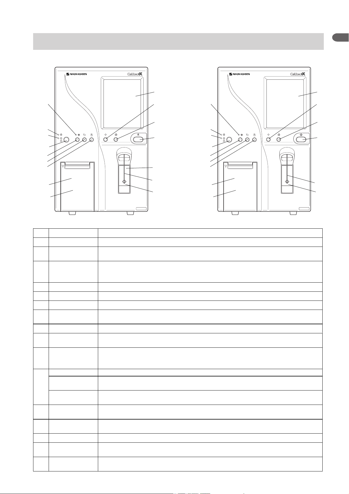
No. Name Description
1 Main power lamp Lights when the [Main power] switch on the rear panel is tuned on.
2Power lamp
Lights when the [Main power] switch on the rear panel and [Power] key on the front panel
are turned on.
Turns the analyzer power on or off when the [Main power] switch on the rear panel is turned
3Power key
on. When the power is turned on, priming and self-check are automatically performed, and
the READY screen appears.
4 Auto print key Switches the printing mode between automatic and manual for the printer.
5 Feed key Feeds paper of the printer while held down.
6 Print key Prints displayed data on the printer.
Auto print mode
7
lamp
Lights when automatic printing mode is selected.
8 LCD display Displays various messages, measured data and touch screen keys.
9 Reset key
Stops operation when pressed during operation. Returns to the READY screen when pressed
while changing settings. Use this key only when an error occurs.
Cleans the fluid path, aperture and manometer with detergent. Automatically primes after
10 Clean key
cleaning the fluid path. Press this key when clogging occurs, the manometer becomes dirty
or bubbles occur in the manometer.
Eject key For closed mode only. Opens the tube holder to set the sample tube. (MEK-6400)
Count key
Dispense key
12 Tube holder
13 Sampling nozzle
Aspirates the sample and starts counting when <[Eject] key operation> is set to “Count” on
the OPERATION screen of the SETTINGS screen. (MEK-6410, MEK-6420)11
Dispenses the diluent in pre-dilution blood mode when <[Eject] key operation > is set to
“Dispense” on the OPERATION screen of the SETTINGS screen. (MEK-6410, MEK-6420)
For closed mode only. Holds a sealed vacuum blood collecting tube. Press the [Eject] key to
open. After measurement, the holder automatically opens. (MEK-6400)
Aspirates the sample. Dispenses the diluent when in the pre-dilution blood mode. (On MEK6400, for open mode only)
14 Count switch Aspirates the sample and starts counting.
Printer unit
15
(WA-640VK)
16 Printer door
Thermal array printer. Prints out measured data and sample ID no. (optional)
For the recording paper of the WA-640VK printer unit. To open, pull the upper left corner
(optional).
Service Manual MEK-6400/6410/6420 1.7
Page 22
1. GENERAL
Right Side Panel
1
2
3
4
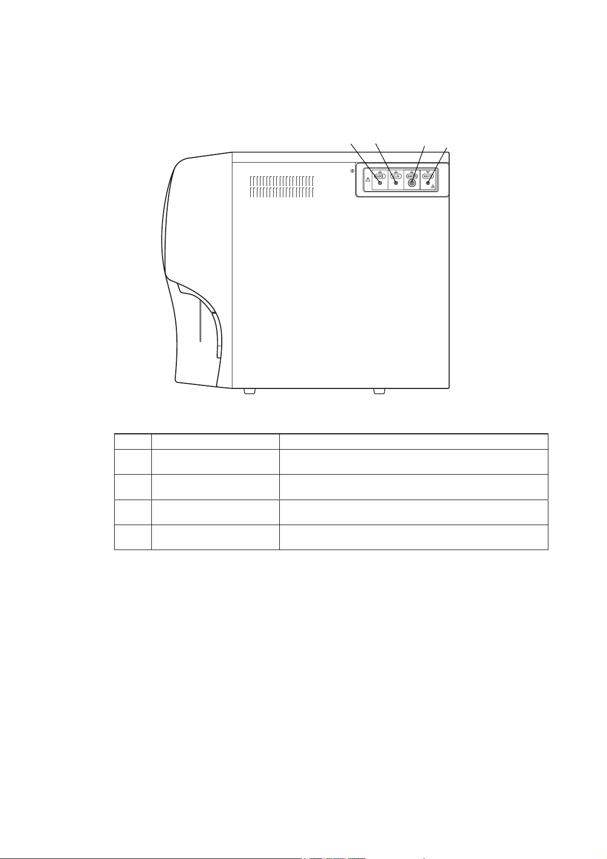
No. Name Description
ISO3
1
Diluent inlet
CLN
2
Detergent inlet
HEMO3N
3
Hemolysing reagent inlet
WA ST E
4
Waste outlet
Inlet for the ISOTONAC•3 diluent.
Inlet for the CLEANAC detergent.
Inlet for the Hemolynac•3N hemolysing reagent.
Outlet for waste such as used lyse, detergent and aspirated
samples.
1.8 Service Manual MEK-6400/6410/6420
Page 23
1. GENERAL
Rear Panel
1
2
3
4
1
5
6
7
8
9
10
11
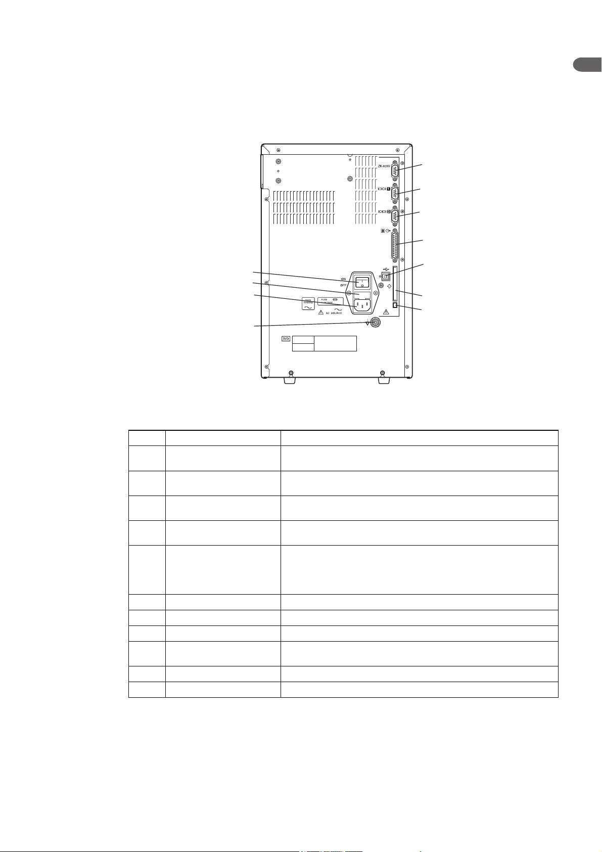
No. Name Description
1 Main power switch
2 Fuse holder
AC SOURCE
3
AC source socket
Equipotential ground
4
terminal
ZK-820V
5
Bar code reader socket
6 Serial port 1 Connects to the optional WA-460V/461V card printer or PC.
7 Serial port 2 Connects to the optional WA-460V/461V card printer or PC.
8 Printer socket Connects to an external printer (WA-710V/712V or other).
9 USB socket
10 Memory card socket Insert a memory card when you upgrade the software.
11 Memory card eject button Press this button when you eject a memory card.
Supplies the power to the analyzer when it is turned on. Under
normal conditions keep this switch turned on.
Contains the time lag fuse. To replace the fuse, contact your
Nihon Kohden representative.
Connects the AC power cord to supply AC power to the analyzer.
Connects the ground lead to the equipotential ground terminal on
the wall for earth grounding.
Connects to the optional hand-held bar code reader.
Supplies the power to the bar code reader when connected.
Power supply voltage: 5 V DC (pin 9: 5 V, pin 5: GND)
Rated current: 200 mA
Connects to a PC. The optional Data Management Software
needs to be installed on the PC to receive data from the analyzer.
Service Manual MEK-6400/6410/6420 1.9
Page 24
1. GENERAL
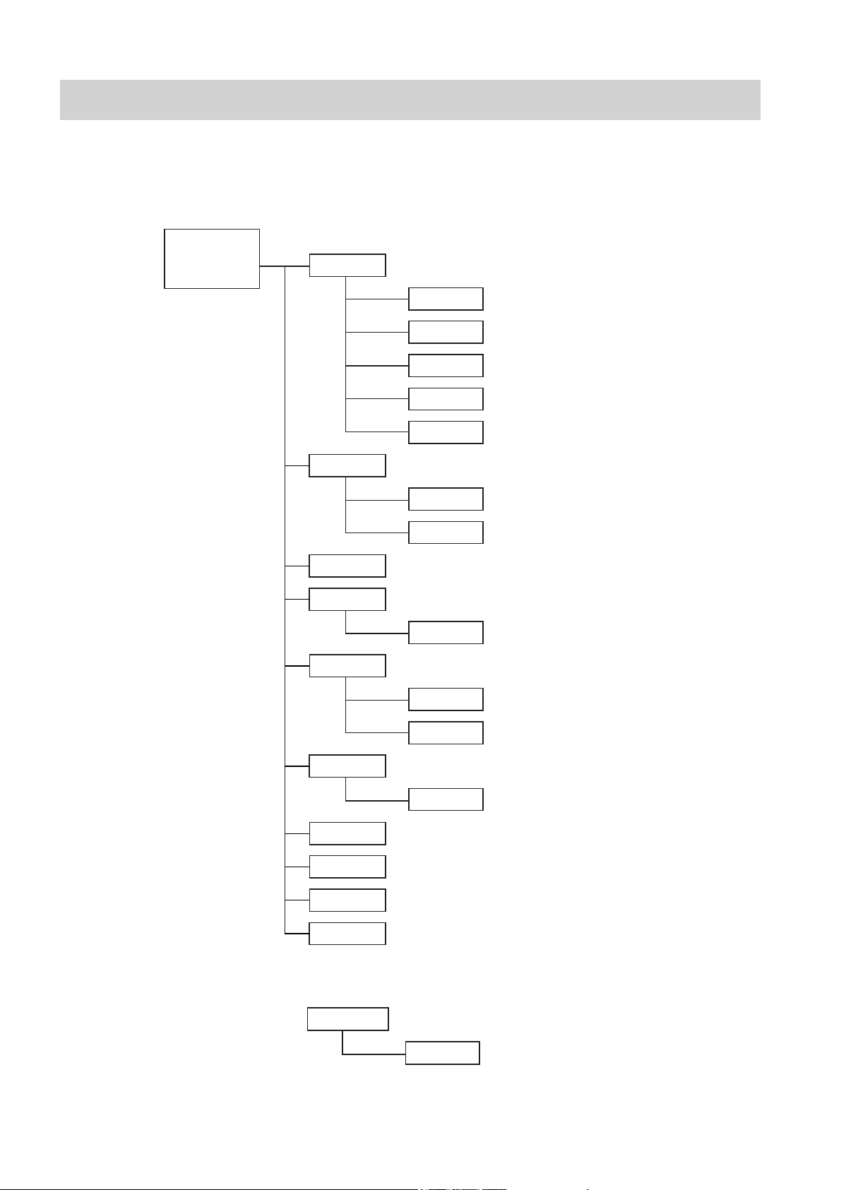
Composition
MEK-6400
Standard
MEK-6400J
MEK-6400K
MEK-6400C
MC-640V Measuring Unit
UT-7198 MEASURING Board
UT-7201 HGB AMP Board
UT-7202 HGB LED Board
XP-612V 2-Way Electromagnetic Value (× 10)
XP-602V 2-Way Electromagnetic Value (× 2)
MD-640V Combination Syringe Pump Unit
UT-7200 MIXED PUMP Board
XP-612V 2-Way Electromagnetic Value (× 4)
MP-640V Pump Unit
PV-641VK Front Panel Unit
UT-7203 KEY Board
JQ-640V Inlet/Outlet Unit
UT-7199 LIQUID SENSOR Board
XP-612V 2-Way Electromagnetic Value (× 2)
JQ-641V Valve Unit
XP-612V 2-Way Electromagnetic Value (× 6)
MS-640V Sampler Unit
MS-641V Cap Pierce Unit
UT-7192 AMP CONTROL Board
UT-7193 POWER Board
Option
WA-640VK Printer Unit
UT-7205 PRINTER DRIVER Board
1.10 Service Manual MEK-6400/6410/6420
Page 25

1. GENERAL
MEK-6410
Standard
MEK-6410J
MEK-6410K
MEK-6410C
1
MC-640V Measuring Unit
UT-7198 MEASURING Board
UT-7201 HGB AMP Board
UT-7202 HGB LED Board
XP-612V 2-Way Electromagnetic Value (× 10)
XP-602V 2-Way Electromagnetic Value (× 2)
MD-640V Combination Syringe Pump Unit
UT-7200 MIXED PUMP Board
XP-612V 2-Way Electromagnetic Value (× 4)
MP-640V Pump Unit
PV-641VK Front Panel Unit
UT-7203 KEY Board
JQ-640V Inlet/Outlet Unit
UT-7199 LIQUID SENSOR Board
XP-612V 2-Way Electromagnetic Value (× 2)
JQ-642V Valve Unit
XP-612V 2-Way Electromagnetic Value (× 4)
MS-640V Sampler Unit
MR-640V Rinse Unit
UT-71921 AMP CONTROL Board
UT-7193 POWER Board
Option
WA-640VK Printer Unit
UT-7205 PRINTER DRIVER Board
Service Manual MEK-6400/6410/6420 1.11
Page 26

1. GENERAL
MEK-6420
Standard
MEK-6420J
MEK-6420K
MEK-6420C
MC-640V Measuring Unit
UT-7198 MEASURING Board
UT-7201 HGB AMP Board
UT-7202 HGB LED Board
XP-612V 2-Way Electromagnetic Value (x 10)
XP-602V 2-Way Electromagnetic Value (x 2)
MD-640V Combination Syringe Pump Unit
UT-7200 MIXED PUMP Board
XP-612V 2-Way Electromagnetic Value (x 4)
MP-640V Pump Unit
PV-641VK Front Panel Unit
UT-7203 KEY Board
JQ-640V Inlet/Outlet Unit
UT-7199 LIQUID SENSOR Board
XP-612V 2-Way Electromagnetic Value (x 2)
JQ-642V Valve Unit
XP-612V 2-Way Electromagnetic Value (x 4)
MS-640V Sampler Unit
MR-640V Rinse Unit
UT-71922 AMP CONTROL Board (MEK-6420J/K)
UT-71923 AMP CONTROL Board (MEK-6420C)
UT-7193 POWER Board
Option
WA-640VK Printer Unit
UT-7205 PRINTER DRIVER Board
1.12 Service Manual MEK-6400/6410/6420
Page 27

1. GENERAL
Interference Substances
WBC: High WBC
When WBC count is outside the measurable range, measure the sample in high dilution mode. If the WBC
count is still outside the range, dilute the sample further.
Nucleated erythrocyte
Nucleated erythrocyte is detected as WBC and causes increase in WBC count.
Unlysed red cells
In some rare occasions, the RBC in the blood sample may not completely lyse and these non-lysed RBC may
be detected as WBC and cause increase in WBC count.
Multiple myeloma
The precipitation of proteins in multiple myeloma patients may increase the WBC count.
Leukemia
WBC is fragile in leukemia patients and WBC may be destroyed during measurement. These WBC fragments
may also interfere with WBC differential measurement.
Chemotherapy
Cytotoxic and immunosuppressive drugs cause low WBC count.
Cryoglobulins
Cryoglobulin may be increased in patients who are pregnant or have myeloma, cancer, leukemia,
macroglobulinemia, lymphoproliferative disorders, metastatic tumors, autoimmune disorders, infections,
aneurysm, thromboembolic phenomena, diabetes, etc, which cause increase in WBC, RBC or PLT counts and
HGB concentration. In such cases, warm the blood sample to 37°C in a water bath for 30 minutes and measure
the sample immediately.
RBC: Leukemia
An increase in WBC in leukemia patient causes increase in RBC.
Agglutinated RBC
Agglutinated RBC may decrease RBC count. This can be checked by abnormal MCH and MCHC values and
examination of the stained blood film.
Cold agglutinins
IgM immunoglobulins which are elevated in clod agglutinin disease may decrease RBC and PLT counts and
increase MCV.
Hemolysis
When RBC is hemolyzed, RBC is decreased.
HGB: Turbidity of the blood sample
Any physiologic and/or therapeutic factors may increase HGB. In such a case, determine the cause of turbidity
and follow the appropriate method below.
1. Increased WBC
An extreme increase in WBC causes excessive light scatter. In these cases, measure manually. Centrifuge
the diluted sample and measure the supernatant fluid with a spectrophotometer.
2. Increased lipids
The blood sample may be milky when there is excessive lipids. This may occur with hyperlipidemia,
hyperproteinemia and hyperbilirubinemia. Accurate HGB measurement can be achieved by manual
methods and a plasma blank.
3. Increased turbidity
When RBC are resistant to lysing, turbidity may increase causing increase in HGB. Observe if MCH and
MCHC values are abnormal. HGB result affects MCH and MCHC result.
4. Fetal bloods
The mixing of fetal and maternal blood may increase HGB value.
1
Service Manual MEK-6400/6410/6420 1.13
Page 28

1. GENERAL
5. High WBC levels
Turbidity of blood increases and the hemoglobin concentration becomes high if WBC level of the blood
sample is high. MCH and MCHC levels also become high.
HCT: Agglutinated RBC
RBC agglutination may cause erroneous HCT and MCV values. Observe if MCH and MCHC values are
abnormal. In such a case, measure manually.
MCV: Agglutinated RBC
RBC agglutination may cause erroneous HCT and MCV values. Observe if MCH and MCHC values are
abnormal. In such a case, measure manually.
Excessive number of large PLT
Excessive number of large PLT and/or excessively high WBC may affect the MCV value. Check by careful
examination of the stained blood film.
MCH: MCH is determined from HGB and RBC values. Therefore, the limitations for HGB and RBC also affect MCH
value.
MCHC: MCHC is determined from HGB and HCT values. Therefore, the limitations for HGB and HCT also affect
MCHC value.
RDW: RDW is determined from RBC value. Therefore, the limitations for RBC also affect RDW value.
Agglutinated RBC
Agglutinated RBC may decrease RBC count and erroneous RDW. This can be checked by abnormal MCH and
MCHC values and examination of the stained blood film.
Nutritional deficiency or blood transfusion
Iron and/or cobalamin and/or folate deficiency may increase RDW.
PLT: Very small fragments
Very small RBC, RBC fragments and WBC fragments may be the cause in increased PLT count.
Agglutinated RBC
PLT may be trapped in the agglutinated RBC resulting in decrease in PLT. This can be checked by abnormal
MCH and MCHC values and examination of the stained blood film.
Very large PLT
Large PLT may exceed the PLT threshold and might not be counted which results in low PLT count.
Chemotherapy
Cytotoxic and immunosuppressive drugs may increase the fragility of cells which may cause low PLT count.
In such a case, measure manually.
Hemolysis
Hemolyzed specimens contain red cell stroma which may increase PLT count.
Anticoagulated blood
Blood anticoagulated with acid-citrate-dextrose may have clumped PLT which may cause decrease in PLT
count.
Agglutinated PLT
Clumped PLT may decrease PLT count and/or increase WBC count. For such sample, collect the sample in
sodium citrate anticoagulant and measure only PLT. The PLT result must be corrected for the sodium citrate
dilution effect.
MPV: Very large PLT
Large PLT may exceed the PLT threshold and not be counted which results in low MPV.
Very small fragments
Very small RBC, RBC fragments and WBC fragments may interfere with MPV measurement.
Agglutinated RBC
PLT may be trapped in the agglutinated RBC resulting in erroneous MPV. This can be checked by abnormal
MCH and MCHC values and examination of the stained blood film.
1.14 Service Manual MEK-6400/6410/6420
Page 29

1. GENERAL
Chemotherapy
Cytotoxic and immunosuppressive drugs may affect MPV. In such a case, measure manually.
NOTE
Blood samples collected in EDTA do not maintain stable MPV because platelets swell
depending on the interval after collection and storage temperature.
WBC differential parameters are derived from the WBC count, therefore, the limitations for WBC also affect these
parameters.
LY and LY%: Erythroblasts, certain parasites and RBC that are resistant to lysis may interfere with an accurate LY
count.
MO and MO%: Large lymphocytes, atypical lymphocytes, blasts and excessive number of basophils may interfere with
an accurate MO count.
GR and GR%: Excessive eosinophils, metamyelocytes, myelocytes, promyelocytes, blasts and plasma cells may
interfere with an accurate GR count and GR%.
EO: Abnormal granules may interfere with an accurate EO count.
1
Service Manual MEK-6400/6410/6420 1.15
Page 30

Section 2 Troubleshooting
Check Procedure Flowchart ............................................................................................................................... 2.4
Operating Condition and Blood Sample Checks ................................................................................................. 2.5
Operating Condition Check ...................................................................................................................... 2.5
Blood Sample Handling Check ................................................................................................................. 2.5
Pre-dilution Sample Preparation Check .................................................................................................... 2.5
Checking the Hematology Analyzer ................................................................................................................... 2.7
Checking Background Noise .................................................................................................................... 2.7
Measurement ................................................................................................................................. 2.7
Parameter Data Check with Diluent ................................................................................................ 2.7
Reducing Background Noise .......................................................................................................... 2.8
Background Noise Problems .......................................................................................................... 2.9
Checking the Reproducibility .................................................................................................................... 2.9
Checking Procedure ....................................................................................................................... 2.9
CV Values ..................................................................................................................................... 2.10
Checking Accuracy ...........................................................................................................................................2.11
Checking Procedure ................................................................................................................................ 2.11
Poor WBC Reproducibility ....................................................................................................................... 2.11
Poor HGB Reproducibility........................................................................................................................2.12
Poor RBC Reproducibility ........................................................................................................................2.13
Poor PLT Reproducibility ......................................................................................................................... 2.14
Poor HCT or MCV Reproducibility ........................................................................................................... 2.15
Solving Problems from Alarm Messages .......................................................................................................... 2.16
A001: No diluent ........................................................................................................................... 2.16
A005: No detergent ....................................................................................................................... 2.16
A007: No lysing reagent ................................................................................................................ 2.17
A009: WBC priming error ............................................................................................................... 2.17
A010: RBC PRIMING ERROR ......................................................................................................2.17
A021: WBC level 1 ........................................................................................................................2.17
A022: WBC level 2 ........................................................................................................................2.18
A023: WBC level 3 ........................................................................................................................2.18
A024: WBC bubble 1 ..................................................................................................................... 2.18
A025: WBC bubble 2 ..................................................................................................................... 2.18
A026: WBC bubble 3 ..................................................................................................................... 2.19
A027: WBC bubble 4 ..................................................................................................................... 2.19
A029: WBC clog ............................................................................................................................2.19
A030: WBC sample error ...............................................................................................................2.19
A031: WBC noise 2 .......................................................................................................................2.20
A032: WBC noise 1 .......................................................................................................................2.20
A036: WBC upper manometer dirty ............................................................................................... 2.20
A037: WBC lower manometer dirty ................................................................................................ 2.20
A041: RBC level 1 ........................................................................................................................ 2.21
A042: RBC level 2 ........................................................................................................................ 2.21
A043: RBC level 3 ........................................................................................................................ 2.21
A044: RBC bubble 1 ...................................................................................................................... 2.22
A045: RBC bubble 2 ...................................................................................................................... 2.22
A046: RBC bubble 3 ...................................................................................................................... 2.22
2
Service Manual MEK-6400/6410/6420 2.1
Page 31

A047: RBC bubble 4 ...................................................................................................................... 2.22
A049: RBC clog ............................................................................................................................ 2.22
A050: RBC sample error ............................................................................................................... 2.23
A051: RBC noise 2 ....................................................................................................................... 2.23
A052: PLT noise 1 ........................................................................................................................ 2.23
A053: PLT noise 3 ........................................................................................................................ 2.23
A057: RBC upper manometer dirty ................................................................................................ 2.23
A058: RBC lower manometer dirty ................................................................................................2.23
A061: HGB voltage low ................................................................................................................. 2.24
A062: HGB voltage high ................................................................................................................ 2.24
A063: HGB circuit error ................................................................................................................. 2.24
A072: Tube holder open .................................................................................................................2.24
A073: Tube in the holder ................................................................................................................2.25
A091: Room temperature high .......................................................................................................2.25
A092: Room temperature low ........................................................................................................ 2.25
A093: Internal temperature high .................................................................................................... 2.25
A094: Internal temperature low ......................................................................................................2.25
A095: Power supply temp high ...................................................................................................... 2.25
! APPEARS ON THE RIGHT OF WBC MEASURED VALUE ........................................................ 2.26
! APPEARS ON THE RIGHT OF MCHC MEASURED VALUE ...................................................... 2.26
C APPEARS ON THE RIGHT OF WBC OR PLT MEASURED VALUE or PLT Clumps appears .... 2.27
OTHER FLAGS............................................................................................................................. 2.27
Solving Problems from System Error Messages ...............................................................................................2.28
E001: DILUTER INITIALIZE ERROR ............................................................................................ 2.28
E021: SAMPLER INITIALIZE ERROR .......................................................................................... 2.28
E041: SUB BATH INITIALIZE ERROR .......................................................................................... 2.28
E101: BATH DRAIN ERROR ......................................................................................................... 2.29
E122: CHECK SETTINGS ............................................................................................................ 2.29
E123: MEMORY ERROR .............................................................................................................. 2.29
E124: CIRCUIT ERROR ................................................................................................................2.29
E126: TOUCH PANEL ERROR ...................................................................................................... 2.29
E141: CAP PIERCE INITIALIZE ERROR ..................................................................................... 2.29
Service Maintenance Screens...........................................................................................................................2.30
Displaying the SERVICE Screen ............................................................................................................. 2.30
CHECK MENU Screen ............................................................................................................................ 2.32
UNIT MAINTE Screen ............................................................................................................................ 2.32
MD-640V ...................................................................................................................................... 2.33
MS-640V ...................................................................................................................................... 2.33
MS-641V (MEK-6400 only) ........................................................................................................... 2.34
MV & PUMP CHK ........................................................................................................................ 2.34
CONT MEASURE Screen .......................................................................................................................2.35
SETTING MENU Screen ........................................................................................................................ 2.35
ADV. SETTINGS Screen ...............................................................................................................2.35
REAGENT FACTOR Screen ......................................................................................................... 2.36
USER MAINTENANCE Screen ..................................................................................................... 2.36
PANIC VALUE Screen (for MEK-6400 and MEK-6410) .................................................................. 2.37
FLAG SETTINGS Screen ............................................................................................................. 2.37
BAR CODE PORT Screen ............................................................................................................2.37
UNIT CAL Screen ......................................................................................................................... 2.38
2.2 Service Manual MEK-6400/6410/6420
Page 32

MONITOR Screen ................................................................................................................................... 2.38
X10-CV screen ....................................................................................................................................... 2.39
INITIAL MENU Screen ............................................................................................................................ 2.40
OTHER MENU Screen ............................................................................................................................2.40
PRINT SETTINGS Screen ...................................................................................................................... 2.40
2
Service Manual MEK-6400/6410/6420 2.3
Page 33

2. TROUBLESHOOTING
Check Procedure Flowchart
Check the hematology analyzer according to the following check procedure flowchart.
Are the following conditions acceptable?
• Reagents
• Temperature
• Blood sample
Ye s
Does the screen appear with no error messages, such
as the following, when the power is turned on?
• No diluent
• No detergent
• No lysing reagent
• xxx ... initialize error
• xxx priming error
No
No
Refer to the “Operating Condition and Blood Sample
Checks” section.
Refer to the “Solving Problems from Alarm Messages”
and “Solving Problems from System Error Messages”
sections.
Ye s
Check the specified parameters after the background
noise measurement.
• Are the WBC, RBC, HGB and PLT data
acceptable?
• Is there no alarm message?
Ye s
Check the following after the MEK-3D hematology
control measurement.
• Is there no alarm message?
• Are the following parameter reproducibility
acceptable?
RBC, HGB, WBC, PLT, HCT and MCV
• Are all the obtained parameters within the
acceptable range on the assay sheet?
Ye s
No
No
Refer to the “Checking Background Noise” section,
“Background Noise Problems” table and “Solving
Problems from Alarm Messages” section.
Refer to the “Solving Problems from Alarm Messages”
and “Checking Accuracy” sections.
END
2.4 Service Manual MEK-6400/6410/6420
Page 34

2. TROUBLESHOOTING
Operating Condition and Blood Sample Checks
Operating Condition Check
Measurement requires the following operating conditions.
• Operating temperature: 15 to 30°C (59 to 86°F)
• Operating humidity: 30 to 85%
• Operating atmospheric pressure:70 to 106 kPa
If the diluent or hemolysing reagent temperature is lower than 15°C, it will
affect the measurement data of HGB, WBC and WBC differential parameters or
cause a hemolysing error or sample error alarm.
Blood Sample Handling Check
• Check that the blood sample is counted immediately after collection or
stored in a cool place (at temperatures between 2 and 8°C, 36 and 46°F) such
as a refrigerator. If the blood sample is stored in a refrigerator at temperatures
lower than 2°C for a long time or left more than 12 hours at room temperature
after collection, the WBC differential parameters may be affected.
1
2
If the blood sample causes hemolysing error when it is counted
within 30 minutes after collection, wait at least 30 minutes after
collection before counting it.
• Measurement data might not be accurate for special blood sample, such as
from a neonate or patient with hepatic disease or special treatment. In most
cases, these blood samples are difficult to hemolyze because RBC have
strong membrane resistance and the analyzer counts high WBC. Bilirubin or
WBC in blood affects MCHC. These special blood samples need a different
measurement method.
Pre-dilution Sample Preparation Check
Most measurement data errors in pre-dilution mode are caused by blood
clotting and dilution of the blood sample. Therefore, check the following
points. When pre-dilution blood is measured, data accuracy depends on careful
clotting and diluting.
NOTE
14
• Before using a sahli pipette for pre-dilution blood collection, check that the
sahli pipette is completely cleaned and dried. An optional microcap (20 µL)
is recommended for pre-dilution blood collection. (Supply code no. T812).
• When putting the pre-dilution blood into a sample cup, make sure there are
no bubbles in the cup. If you cannot avoid making bubbles with the sahli
pipette, we recommend the optional microcap which prevents bubbling.
Service Manual MEK-6400/6410/6420 2.5
Page 35

2. TROUBLESHOOTING
• In pre-dilution mode, about 1 mL of sample is aspirated. Make sure that the
sampling nozzle is near the bottom of the sample cup so that the correct
volume of the sample can be aspirated.
2.6 Service Manual MEK-6400/6410/6420
Page 36

2. TROUBLESHOOTING
Checking the Hematology Analyzer
There are two hematology analyzer checks: background noise and
reproducibility.
Checking Background Noise
Measure the diluent to check the background noise.
Measurement
Count the diluent in closed mode and open mode. Closed mode is only for
MEK-6400.
1. Select “Closed” or “Open” for <Sampling mode> and press the MENU key
on the READY screen.
2. Press the OTHER key on the MENU screen.
1
2
3. Press the BACKGROUND key on the OTHER screen. The “Measure
background noise?” message appears on the screen.
4. Press the YES key to measure background noise. The result is displayed
after the measurement is complete.
Parameter Data Check with Diluent
Check that the background check values are less than or equal to the following
values. Disregard the other parameter values because noise does not affect the
other parameters.
Especially check the data for the PLT parameter because PLT is more affected
by dust particles than the other parameters. When there are dust particles
smaller than the WBC and RBC parameters in the diluent, the WBC and RBC
are not affected by dust but the PLT value increases because the platelets are
about the same size as the dust particles. If PLT is over 10 × 103/µL, do the
action described below to reduce the background noise.
Best values Acceptable values Values in the operator’s
manual
WBC (× 103/µL): 0.0 0.1 0.2
RBC (× 106/µL): 0.00 0.01 0.05
HGB (g/dL): 0.0 0.1 0.1
PLT (× 103/µL): 3 9 10
14
Service Manual MEK-6400/6410/6420 2.7
Page 37

2. TROUBLESHOOTING
Reducing Background Noise
To reduce the background noise when the background check value is outside
the optimal range shown in the previous tables, do the following.
1. Press the [Clean] key on the front panel to perform cleaning. If this does not
reduce the background noise, do the following steps.
2. Thoroughly clean the diluent container with detergent.
3. Wash away any remaining detergent in the hydraulic system with clean
diluent.
4. Perform the background check to make sure that the background noise is
reduced.
If the data of the background check is still not optimum, replace the diluent
with diluent from a new, sealed container.
NOTE
• Once the background noise is reduced and when the instrument is
used every day, the instrument is not severely contaminated.
However, contamination builds up in the instrument and cannot be
easily removed if the instrument is not cleaned periodically.
Periodic maintenance is important for keeping the instrument in
optimum condition.
• When not using the instrument for a long time, clean the fluid path
with diluent. Refer to “Storing and Transporting the Analyzer” in
Section 9 of the Operator’s Manual.
2.8 Service Manual MEK-6400/6410/6420
Page 38

2. TROUBLESHOOTING
Background Noise Problems
Problem Possible Cause/Criteria Countermeasure
High background
noise for all
parameters.
High background
noise of WBC,
RBC and PLT.
High background
noise of HGB.
The diluent or diluent container is dirty.
The fluid path inside the hematology analyzer
is dirty.
Noise interference through AC source or
other instruments nearby.
The reagents are not used in the appropriate
temperature range and they are deteriorated.
The filters are clogged or dirty. Clean or replace the filters with new ones.
The measurement baths and sub baths are
dirty.
The apertures are dirty. Clean or replace the apertures with new ones.
The rinse unit is dirty. Clean the rinse unit.
The apertures are damaged. Replace the apertures with new one.
The MC-640V measuring unit is damaged. Replace the unit with a new one.
The sampling nozzle is clogged. Replace the sampling nozzle with a new one.
The MD-640V combination syringe pump
unit failure.
The UT-7192 AMP CONTROL board
failure.
The UT-7193 POWER board failure. Replace the board with a new one.
The reagent is dirty. Replace the reagent with a new one.
The measurement baths and sub baths are
dirty.
The MC-640V measuring unit failure. Replace the unit with a new one.
The UT-7201 HGB AMP board failure. Replace the board with a new one.
The UT-7202 HGB LED board failure. Replace the board with a new one.
The UT-7192 AMP CONTROL board
failure.
The UT-7193 POWER board failure. Replace the board with a new one.
The reagent is dirty. Replace the reagent with a new one.
Clean the diluent container or replace the diluent
with new one.
Press the [Clean] key on the front panel to perform
cleaning.
Perform strong cleaning.
Connect the hematology analyzer power cord to
another AC outlet. If possible, use an independent
AC outlet only for the hematology analyzer.
Perform equipotential grounding and remove the
other instruments if they are the cause of noise.
Use the reagents in the appropriate temperature
range.
Clean or replace the measurement baths and sub
baths with new ones.
Replace the unit with a new one.
Replace the board with a new one.
Clean or replace the measurement baths and sub
baths with new ones.
Replace the board with a new one.
1
2
14
Checking the Reproducibility
This check is used to check reproducibility of the instrument, using printout of
the CV values of 10 data of a diluted sample of the same MEK-3DN
hematology control. When the CV values are out of the specification range, the
reproducibility of the instrument is poor. If the reproducibility is found to be
poor, this printed result is used to troubleshoot the instrument.
Checking Procedure
1. Reduce the background noise.
2. Warm the sample (MEK-3DN) to room temperature (15 to 30°C, 59 to 86°F)
and stir it sufficiently.
3. Measure the sample 10 times.
Service Manual MEK-6400/6410/6420 2.9
Page 39

2. TROUBLESHOOTING
4. Press the MENU → OTHER → SERVICE → X10-CV key to display the
result and check the CV data. (The type of user must be “Service” to enter
the SERVICE screen.)
CV Values
The reproducibility is checked using the CV values. The CV value is acquired
by dividing the standard deviation by the average value. When the CV value is
large, it indicates that the measurement data variability is large (i.e.
reproducibility is poor).
Example
Parameters
WBC
LY% 5.0
MO% 12.0
GR% 5.0
RBC
HGB 13.0 (g/dL) 0.7 1.5
MCV 91 (fL) 0.4 1.0
PLT
MPV 1.0
Measured Value
(average)
6.8 (×103/µL)
4.43 (×106/µL)
242 (×103/µL)
Acquired CV
(%)
1.3 2.0
0.8 1.5
3.2 4.0
Standard CV
(%)
In the above example, the RBC measured value is 4.43 and the acquired CV is
0.8%. 0.8% of 4.43 is 0.035, 4.43 ± 0.035 is 4.465 and 4.395. Therefore, the CV
of 0.8% indicates that in 6 of 10 measurements, the acquired value is between
4.395 and 4.465.
4.37 4.39 4.40 4.43 4.44 4.45 4.45 4.46 4.47 4.48
(2 data) (6 data) (2 data)
4.395 4.465
Reference
The reproducibility depends on the number of counted cells. When this number
increases, the reproducibility is improved. Therefore, if the number of counted
cells is small (a sample with low concentration is measured), the variation
increases. For example, the CV is within 4% when counting 300,000 PLT, but
the CV increases to over 4% when counting 100,000 PLT. This is a common
feature for any hematology analyzer.
2.10 Service Manual MEK-6400/6410/6420
Page 40

2. TROUBLESHOOTING
Checking Accuracy
Checking Procedure
1
2
Before checking accuracy, measure a MEK-3DN hematology control with the
procedure described in the “Checking the Reproducibility” section. Confirm
that the obtained sample data is within the acceptable range on the assay sheet
attached to the hematology control. If the data is outside this range or on the
borderline, calibrate the hematology analyzer with the following procedure.
1. Measure the MEK-3DN hematology control 10 times on the
CALIBRATION screen.
2. Calibrate the instrument. Refer to Section 7 “Calibration” in the Operator’s
Manual.
3. Remeasure the hematology control. Confirm that the obtained sample data
is within the acceptable range on the assay sheet attached to the
hematology control.
Poor WBC Reproducibility
The following may be the main reasons for poor WBC reproducibility.
• Measuring unit and fluid path are dirty
• Reagent is deteriorated.
• Samples are not stirred enough.
• Hematology analyzer failure.
Measurement baths, rinse unit or fluid path is dirty
Possible Cause/Criteria Countermeasure
WBC measurement bath is dirty.
Rinse unit is dirty. Clean the rinse unit.
WBC aperture is dirty. Clean or replace the WBC aperture with a new one.
Deterioration of reagents
Possible Cause/Criteria Countermeasure
The specified reagents are not used. Use only the specified reagents.
Deterioration of reagents.
The reagents are used outside the specified temperature range. Use the reagents in the appropriate temperature.
Press the [Clean] key on the front panel to perform cleaning.
Perform strong cleaning.
Clean the WBC measurement bath.
Replace the WBC sub bath with a new one.
Replace the WBC measurement bath with a new one.
Replace the hemoglobin filter below air trap with a new one.Drain path of WBC measurement bath is dirty.
Clean the air trap with a cotton swab.
Replace the reagents with new one.
Use the reagents in appropriate conditions.
14
Service Manual MEK-6400/6410/6420 2.11
Page 41

2. TROUBLESHOOTING
Samples are not stirred enough
Possible Cause/Criteria Countermeasure
The sample was not stirred thoroughly before measurement. Stir the sample thoroughly before measurement.
Hematology analyzer failure
Possible Cause/Criteria Countermeasure
The appropriate amount of hemolyzing
reagent is not dispensed.
Circuit malfunction
(WBC is outside 8.0 ±5% when circuit check
is performed by pressing MENU key
OTHER key → CIRCUIT CHECK key)
WBC sample error
→
Put the HEMOLYNAC3 tube assay into the middle of the bottle.
Replace the HEMOLYNAC3 tube assay with a new one.
Replace the MD-640V combination syringe pump unit with a new one.
Replace the MC-640V measuring unit with a new one.
Replace the UT-7198 MEASURING board with a new one.
Replace the UT-7192 AMP CONTROL board with a new one.
Replace the MD-640V combination syringe pump unit with a new one.
In closed mode, replace the MS-641V cap pierce unit with a new one.
In open mode, replace the MS-640V sampler unit with a new one.
Poor HGB Reproducibility
The following may be the main reasons for poor HGB reproducibility.
• Measuring unit and fluid path are dirty.
• Reagent is deteriorated.
• Samples are not stirred enough.
• Hematology analyzer failure.
Measurement bath, rinse unit or fluid path is dirty
Possible Cause/Criteria Countermeasure
WBC measurement bath is dirty.
dirty.
Rinse unit is dirty. Clean the rinse unit.
Deterioration of reagents
Possible Cause/Criteria Countermeasure
The specified reagents are not used. Use only the specified reagents.
Deterioration of reagents.
The reagents are used outside the specified temperature range. Use the reagents in the appropriate temperature.
Press the [Clean] key on the front panel to perform cleaning.
Perform strong cleaning.
Clean the WBC measurement bath.
Replace the WBC sub bath with a new one.
Replace the WBC measurement bath with a new one.
Replace the hemoglobin filter below air trap with a new one.Drain path of the WBC measurement bath is
Clean the air trap with a cotton swab.
Replace the reagents with new one.
Use the reagents in appropriate conditions.
Samples are not stirred enough
Possible Cause/Criteria Countermeasure
The sample was not stirred thoroughly before measurement. Stir the sample thoroughly before measurement.
2.12 Service Manual MEK-6400/6410/6420
Page 42

2. TROUBLESHOOTING
Hematology analyzer failure
Possible Cause/Criteria Countermeasure
The appropriate amount of hemolyzing
reagent is not dispensed.
HGB sample error
HGB sensor output failure
(HGB ON item is outside 1.5 to 4.5 V
range when sensor check is performed by
pressing MENU key → OTHER key
SENSOR MONITOR key)
Poor RBC Reproducibility
Put the HEMOLYNAC3 tube assay into the middle of the bottle.
Replace the HEMOLYNAC3 tube assay with a new one.
Replace the MD-640V combination syringe pump unit with a new one.
Replace the MD-640V combination syringe pump unit with a new one.
In closed mode, replace the MS-641V cap pierce unit with a new one.
In open mode, replace the MS-640V sampler unit with a new one.
Adjust the HGB variable resistance volume so that HGB ON item is 3.0 V
1 V. Refer to “Adjusting the HGB Sensor Output Voltage” in Section 5.
±
Replace the MC-640V measuring unit with a new one.
→
Replace the UT-7201 HGB AMP board with a new one.
Replace the UT-7202 HGB LED board with a new one.
Replace the UT-7192 AMP CONTROL board with a new one.
The following may be the main reasons for poor RBC reproducibility.
• Measuring unit and fluid path are dirty.
• Samples are not stirred enough.
• Hematology analyzer failure.
1
2
Measurement bath, rinse unit or fluid path is dirty
Possible Cause/Criteria Countermeasure
RBC measurement bath is dirty.
Drain path of the RBC measurement bath is
dirty.
Rinse unit is dirty. Clean the rinse unit.
RBC aperture is dirty. Clean or replace the RBC aperture with a new one.
Samples are not stirred enough
Possible Cause/Criteria Countermeasure
The sample was not stirred thoroughly before measurement. Stir the sample thoroughly before measurement.
Hematology analyzer failure
Possible Cause/Criteria Countermeasure
Circuit malfunction
(RBC is outside 1.60 ±5% when circuit
check is performed by pressing MENU key
OTHER key → CIRCUIT CHECK key)
→
RBC sample error
Press the [Clean] key on the front panel to perform cleaning.
Perform strong cleaning.
Clean the RBC measurement bath.
Replace the RBC sub bath with a new one.
Replace the RBC measurement bath with a new one.
Clean or replace the filter below RBC measurement bath with a new
one.
Replace the MC-640V measuring unit with a new one.
Replace the UT-7198 MEASURING board with a new one.
Replace the UT-7192 AMP CONTROL board with a new one.
Replace the MD-640V combination syringe pump unit with a new one.
In closed mode, replace the MS-641V cap pierce unit with a new one.
In open mode, replace the MS-640V sampler unit with a new one.
14
Service Manual MEK-6400/6410/6420 2.13
Page 43

2. TROUBLESHOOTING
Poor PLT Reproducibility
The following may be the main reasons for poor PLT reproducibility.
• Background noise is high. PLT measurement is highly sensitive. Therefore,
the background noise must be within the acceptable range (PLT < 10 × 103/
µL). Before checking the PLT reproducibility, check the background noise.
• Samples are not stirred enough.
• Measurement settings are inappropriate.
• Dilution error.
• Hematology analyzer failure.
Background noise is high
Possible Cause/Criteria Countermeasure
The diluent is dirty. Replace the diluent with a new one.
The diluent bottle is dirty. Clean the diluent bottle.
The fluid path is dirty.
Rinse unit is dirty. Clean the rinse unit.
The sampling nozzle is clogged. Replace the sampling nozzle with a new one.
The aperture is damaged. Replace the aperture with a new one.
The MC-640V measuring unit failure Replace the unit with a new one.
Circuit malfunction
(PLT is outside 160 ±5% when circuit check
is performed by pressing MENU key
OTHER key → CIRCUIT CHECK key)
→
Press the [Clean] key on the front panel to perform cleaning.
Perform strong cleaning.
Clean the sub baths and measurement baths.
Clean or replace the filter below the RBC measurement bath with a new
one.
Clean the apertures.
Replace the measurement baths and sub baths with new ones.
Replace the aperture with a new one.
Connect the power cord to another AC outlet.Noise through AC source
Put a noise cut filter on the power cord.
Perform equipotential grounding.Noise interference
Move the instrument which is producing the noise away from the
hematology analyzer.
Replace the UT-7198 MEASURING board with a new one.
Replace the MC-640V measuring unit with a new one.
Replace the UT-7192 AMP CONTROL board with a new one.
Samples are not stirred enough
Possible Cause/Criteria Countermeasure
The sample was not stirred thoroughly before measurement. Stir the sample thoroughly before measurement.
Inappropriate measurement settings
Possible Cause/Criteria Countermeasure
The sensitivity and threshold settings are not
appropriate.
Dilution error
Possible Cause/Criteria Countermeasure
The MD-640V combination syringe pump
unit failure.
2.14 Service Manual MEK-6400/6410/6420
Check that the sensitivity and threshold settings are set as below.
RBC SENSITIVITY: 5
RBC THRESHOLD: AUTO
PLT THRESHOLD: 5
Replace the sampling nozzle with a new one.The MS-640V sampler unit failure.
Replace the unit with a new one.
Replace the unit with a new one.
Page 44

2. TROUBLESHOOTING
Hematology analyzer failure
Possible Cause/Criteria Countermeasure
The aperture is dirty. Clean the aperture.
The aperture is damaged. Replace the aperture with a new one.
Circuit malfunction
(PLT is outside 160 ±5% when circuit check
is performed by pressing MENU key
OTHER key → CIRCUIT CHECK key)
The MC-640V measuring unit is not
attached properly.
The MC-640V measuring unit failure. Replace the unit with a new one.
→
Replace the UT-7198 MEASURING board with a new one.
Replace the MC-640V measuring unit with a new one.
Replace the UT-7192 AMP CONTROL board with a new one.
Reattach the unit. Make sure to tighten the screws attaching the unit to
the chassis. Refer to “Removing the Measuring Unit” in Section 4.
Poor HCT or MCV Reproducibility
The following may be the main reasons for poor HCT or MCV reproducibility.
• Measuring unit is dirty
• Measurement settings are inappropriate.
• Hematology analyzer failure.
1
2
Measuring unit is dirty
Possible Cause/Criteria Countermeasure
Measurement baths and sub baths are dirty. Clean the measurement baths and sub baths.
Aperture is dirty. Clean the aperture.
Inappropriate measurement settings
Possible Cause/Criteria Countermeasure
The sensitivity and threshold settings are not
appropriate.
Hematology analyzer failure
Possible Cause/Criteria Countermeasure
The aperture is damaged. Replace the aperture with a new one.
Circuit malfunction
(RBC is outside 1.60 ±5% when circuit
check is performed by pressing MENU key
OTHER key → CIRCUIT CHECK key)
→
RBC sample error
Check that the sensitivity and threshold settings are set as below.
RBC SENSITIVITY: 5
RBC THRESHOLD: AUTO
Replace the MC-640V measuring unit with a new one.
Replace the UT-7198 MEASURING board with a new one.
Replace the UT-7192 AMP CONTROL board with a new one.
Replace the MD-640V combination syringe pump unit with a new one.
In closed mode, replace the MS-641V cap pierce unit with a new one.
In open mode, replace the MS-640V sampler unit with a new one.
14
Service Manual MEK-6400/6410/6420 2.15
Page 45

2. TROUBLESHOOTING
Solving Problems from Alarm Messages
A001: No diluent
This message appears when the sensor in the tank does not detect the diluent during measurement, priming or cleaning.
Reason Possible Cause/Criteria Countermeasure
No diluent in the
tank
Air bubbles
Failure of the
sensor in the tank
Wrong tube The cleanac tube 8 (tube for CLEANAC3)
Out of diluent. Replace diluent.
The tube between the hematology analyzer
and diluent is squeezed, bent, clogged or
there is leakage.
Leakage in the fluid path. Check the fluid path. If necessary, replace tubes.
Pump tube is damaged. Replace the pump tube with a new one.
The MP-640V pump unit failure. Replace the unit with a new one.
The MD-640V combination syringe pump
unit failure.
The UT-7192 AMP CONTROL board
failure.
The UT-7193 POWER board failure. Replace the board with a new one.
When the hematology analyzer is left
unused, the diluent inside the tank may
evaporate and enter the fluid path as air
bubbles.
Leakage in the fluid path. Check the fluid path. If necessary, replace tubes.
Air bubbles on the liquid sensor. Perform priming.
Voltage adjustment error of the liquid
sensor.
Liquid sensor failure. Replace the UT-7199 LIQUID SENSOR board with
is used for diluent.
Check the tube connection and if necessary, replace
the tube with a new one.
Replace the unit with a new one.
Replace the board with a new one.
Press the [Clean] key to perform cleaning, press the
[Reset] and [Power] keys together to turn the power
off, then press the [Power] key to turn on.
Adjust the voltage. Refer to “Adjusting the Liquid
Sensor Output Voltages” in Section 5.
a new one.
Use the diluent tube.
A005: No detergent
This message appears when the liquid sensors on the JQ-640V inlet/outlet unit do not detect the detergent during
priming or cleaning.
Reason Possible Cause/Criteria Countermeasure
No detergent
flow
Failure of the
sensor in the tank
The tube between the hematology analyzer
and CLEANAC detergent is squeezed, bent,
clogged or there is leakage.
Pump tube is damaged. Replace the pump tube with a new one.
The MC-640V measuring unit failure. Replace the unit with a new one.
The MP-640V pump unit failure. Replace the unit with a new one.
Air bubbles on the liquid sensor. Perform priming.
Voltage adjustment error of the liquid
sensor.
Liquid sensor failure. Replace the UT-7199 LIQUID SENSOR board with
Check the tube connection and if necessary, replace
the tube with a new one.
Adjust the voltage. Refer to “Adjusting the Liquid
Sensor Output Voltages” in Section 5.
a new one.
2.16 Service Manual MEK-6400/6410/6420
Page 46

2. TROUBLESHOOTING
A007: No lysing reagent
This message appears when the sensors on the JQ-640V inlet/outlet unit do not detect the hemolysing reagent during
measurement, priming or cleaning.
Reason Possible Cause/Criteria Countermeasure
No hemolyzing
reagent flow
Failure of the
sensor
A009: WBC priming error
This message appears when diluent cannot be primed during priming the WBC manometer (manometer upper or lower
sensor does not detect the diluent).
Reason Possible Cause/Criteria Countermeasure
Liquid cannot be
detected even when
there is enough liquid
(LED does not light)
manometer
The tube between the hematology analyzer
and HEMOLYNAC3 hemolysing reagent is
squeezed, bent, clogged or there is leakage.
The MD-640V combination syringe pump
unit failure.
Air bubbles on the liquid sensor. Perform priming.
Voltage adjustment error of the liquid sensor. Adjust the voltage. Refer to “Adjusting the Liquid
Liquid sensor failure. Replace the UT-7199 LIQUID SENSOR Board with
WBC manometer upper sensor adjustment error.
WBC manometer lower sensor adjustment error.
The MC-640V measuring unit failure. Replace the unit with a new one.
WBC aperture is not attached properly. Reattach the WBC aperture.Air bubbles in the
The MC-640V measuring unit failure. Replace the unit with a new one.
Check the tube connection and if necessary, replace
the tube with a new one.
Replace the unit with a new one.
Sensor Output Voltages” in Section 5.
a new one.
Adjust the sensor. Refer to “Adjusting the
Upper and Lower Sensor Output Voltages of
the Manometers” in Section 5.
1
2
A010: RBC PRIMING ERROR
This message appears when diluent cannot be primed during priming the RBC manometer (manometer upper or lower
sensor does not detect the diluent).
Reason Possible Cause/Criteria Countermeasure
Liquid cannot be
detected even when
there is enough liquid
(LED does not light)
manometer
A021: WBC level 1
This message appears when the manometer upper sensor does not detect no liquid at the start of WBC measurement or
draining liquid from the manometer.
Reason Possible Cause/Criteria Countermeasure
Liquid is drained
but liquid cannot be
detected (LED does
not turn off)
Liquid cannot be
drained
RBC manometer upper sensor adjustment error.
RBC manometer lower sensor adjustment error.
The MC-640V measuring unit failure. Replace the unit with a new one.
RBC aperture is not attached properly. Reattach the RBC aperture.Air bubbles in the
The MC-640V measuring unit failure. Replace the unit with a new one.
WBC manometer is dirty. Perform strong cleaning.
WBC manometer upper sensor
adjustment error.
The MC-640V measuring unit failure. Replace the unit with a new one.
Pump tube is damaged. Replace the pump tube with a new one.
The MP-640V pump unit failure. Replace the unit with a new one.
The UT-7193 POWER board failure. Replace the board with a new one.
The MC-640V measuring unit failure. Replace the unit with a new one.
Electromagnetic valve failure.
Adjust the sensor. Refer to “Adjusting the Upper and
Lower Sensor Output Voltages of the Manometers” in
Section 5.
Replace the UT-7192 AMP CONTROL board with a
new one.
Replace the UT-7193 POWER board with a new one.
Adjust the sensor. Refer to “Adjusting the
Upper and Lower Sensor Output Voltages of
the Manometers” in Section 5.
14
Service Manual MEK-6400/6410/6420 2.17
Page 47

2. TROUBLESHOOTING
A022: WBC level 2
This message appears when the manometer upper sensor detects no liquid but the lower sensor does not detect no liquid
at the start of WBC measurement or draining liquid from the manometer.
Reason Possible Cause/Criteria Countermeasure
Liquid is drained
but liquid cannot be
detected (LED does
not turn off)
Liquid cannot be
drained
WBC manometer is dirty. Perform strong cleaning.
WBC manometer lower sensor
adjustment error.
The MC-640V measuring unit failure. Replace the unit with a new one.
Pump tube is damaged. Replace the pump tube with a new one.
The MP-640V pump unit failure. Replace the unit with a new one.
The UT-7193 POWER board failure. Replace the board with a new one.
The MC-640V measuring unit failure. Replace the unit with a new one.
Electromagnetic valve failure.
Adjust the sensor. Refer to “Adjusting the Upper and
Lower Sensor Output Voltages of the Manometers” in
Section 5.
Replace the UT-7192 AMP CONTROL board with a
new one.
Replace the UT-7193 POWER board with a new one.
A023: WBC level 3
This message appears when the manometer lower sensor does not detect the liquid during WBC measurement or
aspirating sample.
Reason Possible Cause/Criteria Countermeasure
The pump tube is damaged. Replace the pump tube with a new one.Cannot produce measuring
pressure
produced but there is leakage
produced but there is clog
The MC-640V measuring unit failure. Replace the unit with a new one.
WBC aperture is not attached properly. Reattach the WBC aperture properly.Measuring pressure can be
The MC-640V measuring unit failure. Replace the unit with a new one.
WBC aperture is clogged. Clean or replace the aperture with a new one.Measuring pressure can be
The MC-640V measuring unit failure. Replace the unit with a new one.
A024: WBC bubble 1
This message appears when the manometer upper or lower sensor detects no liquid during WBC measurement or at the
start of draining manometer.
Reason Possible Cause/Criteria Countermeasure
Diluent cannot be
detected even when
there is enough
diluent (LED does
not light)
WBC manometer is dirty. Perform Strong Cleaning.
WBC manometer upper sensor
adjustment error.
WBC manometer lower sensor
Adjust the sensor. Refer to “Adjusting the Upper and
Lower Sensor Output Voltages of the Manometers” in
Section 5.
adjustment error.
The MC-640V measuring unit failure. Replace the unit with a new one.
Air bubbles in the
manometer
WBC manometer is dirty. Perform strong cleaning.
WBC aperture is not attached properly. Reattach the WBC aperture with a new one.
The MC-640V measuring unit failure. Replace the unit with a new one.
A025: WBC bubble 2
This message appears when the manometer upper sensor detects the liquid during WBC measurement or draining
manometer (from upper sensor OFF to lower sensor OFF).
Reason Possible Cause/Criteria Countermeasure
WBC manometer is dirty. Perform strong cleaning.Air bubbles in the
manometer
The MC-640V measuring unit failure. Replace the unit with a new one.
2.18 Service Manual MEK-6400/6410/6420
Page 48

2. TROUBLESHOOTING
A026: WBC bubble 3
This message appears when the manometer lower sensor detects no liquid during WBC measurement or aspirating sample
(from lower sensor ON to upper sensor ON).
Reason Possible Cause/Criteria Countermeasure
Air bubbles in the
manometer
A027: WBC bubble 4
This message appears when the WBC measurement or aspirating sample time is too short (from lower sensor ON to upper
sensor ON).
Reason Possible Cause/Criteria Countermeasure
large.
manometer
A029: WBC clog
This message appears when the manometer lower sensor detects the liquid but the upper sensor does not detect the liquid
during WBC measurement or aspirating sample.
WBC manometer is dirty. Perform strong cleaning.
WBC aperture is not attached properly. Reattach the WBC aperture.
The MC-640V measuring unit failure. Replace the unit with a new one.
WBC aperture is damaged. Replace the WBC aperture with a new one.The aperture is too
Incorrect aperture (100 µm). Use an appropriate aperture (80 µm).
No liquid. Perform priming.Air bubbles in the
The MC-640V measuring unit failure. Replace the unit with a new one.
1
2
Reason Possible Cause/Criteria Countermeasure
Measuring pressure can
be produced but there
is clog
measuring pressure
Measuring pressure can
be produced but there
is leakage
Measuring at high
altitude (higher than
1,000 m above sea
level)
A030: WBC sample error
This message appears when the voltage between the electrodes is out of acceptable range.
Reason Possible Cause/Criteria Countermeasure
Diluted sample error
for WBC count
WBC aperture is clogged. Clean or replace the WBC aperture with a new one.
The MC-640V measuring unit failure. Replace the unit with a new one.
The pump tube is damaged. Replace the pump tube with a new one.Cannot produce
The MC-640V measuring unit failure. Replace the unit with a new one.
WBC aperture is not attached properly. Reattach the WBC aperture properly.
The MC-640V measuring unit failure. Replace the unit with a new one.
High altitude mode needs to be set to
On.
The diluent temperature is too low.
Specified reagents are not used. Only use the specified reagents.
Set “High altitude” on ADVANCED
SET/SETTINGS MENU of the SERVICE screen
must be set to On.
The environment temperature must be from 15 to 30°C.
14
Service Manual MEK-6400/6410/6420 2.19
Page 49

2. TROUBLESHOOTING
A031: WBC noise 2
This message appears when there is baseline wandering during measurement.
A032: WBC noise 1
This message appears when the time sequence of counted pulse is not stable.
Reason Possible Cause/Criteria Countermeasure
Power line
Influence
from other
malfunction
Measuring
unit failure
2 pin power cord is used. Use 3 pin power cord.
Ground lead is not connected. Perform equipotential grounding.
Decrease in the power voltage. Do not share the power source with any other instrument.
Measurement baths and apertures are dirty. Clean or replace the measurement baths and apertures
with new ones.
Perform strong cleaning.
High background noise. Refer to “Background Noise Problems” earlier in this
section.
Poor hemolyzation of the sample. Refer to “! Appears on the right on WBC measured
value” later in this section.
Sample aspiration is not stable (clog
alarm).
WBC aperture is dirty. Perform strong cleaning.
WBC aperture is damaged. Replace the WBC aperture with a new one.
The screw securing the measurement bath
is loose.
The MC-640V measuring unit and chassis
are not insulated (there may be leakage).
The MC-640V measuring unit failure. Replace the unit with a new one.
Refer to “A029: WBC clog”.
Clean the WBC aperture.
Tighten the screw.
Remove the cause.
A036: WBC upper manometer dirty
The voltage of the upper liquid sensor on the manometer is 2.25 to 2.75V.
Reason Possible Cause/Criteria Countermeasure
Manometer is dirty The WBC manometer is dirty. Perform strong cleaning.
Sensor voltage
adjustment error
WBC manometer upper sensor adjustment
error.
Adjust the WBC manometer upper sensor. Refer to
“Adjusting the Upper and Lower Sensor Output
Voltages of the Manometers” in Section 5.
A037: WBC lower manometer dirty
The voltage of the lower liquid sensor on the manometer is 2.25 to 2.75V.
Reason Possible Cause/Criteria Countermeasure
Manometer is dirty The WBC manometer is dirty. Perform strong cleaning.
Sensor voltage
adjustment error
WBC manometer lower sensor adjustment
error.
Adjust the WBC manometer lower sensor. Refer to
“Adjusting the Upper and Lower Sensor Output
Voltages of the Manometers” in Section 5.
2.20 Service Manual MEK-6400/6410/6420
Page 50

2. TROUBLESHOOTING
A041: RBC level 1
This message appears when the manometer upper sensor does not detect no liquid at the start of RBC measurement or
draining liquid from the manometer.
Reason Possible Cause/Criteria Countermeasure
Liquid is drained
but liquid cannot be
detected (LED does
not turn off)
Liquid cannot be
drained
A042: RBC level 2
This message appears when the manometer upper sensor detects no liquid but the lower sensor does not detect no liquid
at the start of RBC measurement or draining liquid from the manometer.
Reason Possible Cause/Criteria Countermeasure
Liquid is drained
but liquid cannot be
detected (LED does
not turn off)
Liquid cannot be
drained
RBC manometer is dirty. Perform strong cleaning.
RBC manometer upper sensor
adjustment error.
The MC-640V measuring unit failure. Replace the unit with a new one.
Pump tube is damaged. Replace the pump tube with a new one.
The MP-640V pump unit failure. Replace the unit with a new one.
The UT-7193 POWER board failure. Replace the board with a new one.
The MC-640V measuring unit failure. Replace the unit with a new one.
Electromagnetic valve failure.
RBC manometer is dirty. Perform strong cleaning.
RBC manometer lower sensor
adjustment error.
The MC-640V measuring unit failure. Replace the unit with a new one.
Pump tube is damaged. Replace the pump tube with a new one.
The MP-640V pump unit failure. Replace the unit with a new one.
The UT-7193 POWER board failure. Replace the board with a new one.
The MC-640V measuring unit failure. Replace the unit with a new one.
Electromagnetic valve failure.
Adjust the sensor. Refer to “Adjusting the Upper and
Lower Sensor Output Voltages of the Manometers” in
Section 5.
Replace the UT-7192 AMP CONTROL board with a
new one.
Replace the UT-7193 POWER board with a new one.
Adjust the sensor. Refer to “Adjusting the Upper and
Lower Sensor Output Voltages of the Manometers” in
Section 5.
Replace the UT-7192 AMP CONTROL board with a
new one.
Replace the UT-7193 POWER board with a new one.
1
2
14
A043: RBC level 3
This message appears when the manometer lower sensor does not detect the liquid during RBC measurement or
aspirating sample.
Reason Possible Cause/Criteria Countermeasure
The pump tube is damaged. Replace the pump tube with a new one.Cannot produce measuring
pressure
produced but there is leakage
produced but there is clog
Service Manual MEK-6400/6410/6420 2.21
The MC-640V measuring unit failure. Replace the unit with a new one.
RBC aperture is not attached properly. Reattach the RBC aperture properly.Measuring pressure can be
The MC-640V measuring unit failure. Replace the unit with a new one.
RBC aperture is clogged. Clean or replace the aperture with a new one.Measuring pressure can be
The MC-640V measuring unit failure. Replace the unit with a new one.
Page 51

2. TROUBLESHOOTING
A044: RBC bubble 1
This message appears when the manometer upper or lower sensor detects no liquid during RBC measurement or at the
start of draining manometer.
Reason Possible Cause/Criteria Countermeasure
Diluent cannot be
detected even when
there is enough
diluent (LED does
not light)
RBC manometer is dirty. Perform strong cleaning.
RBC manometer upper sensor adjustment
error.
RBC manometer lower sensor adjustment
Adjust the sensor. Refer to “Adjusting the Upper and
Lower Sensor Output Voltages of the Manometers” in
Section 5.
error.
The MC-640V measuring unit failure. Replace the unit with a new one.
Air bubbles in the
manometer
RBC manometer is dirty. Perform strong cleaning.
RBC aperture is not attached properly. Reattach the RBC aperture with a new one.
The MC-640V measuring unit failure. Replace the unit with a new one.
A045: RBC bubble 2
This message appears when the manometer upper sensor detects the liquid during RBC measurement or when draining
manometer (from upper sensor OFF to lower sensor OFF).
Reason Possible Cause/Criteria Countermeasure
RBC manometer is dirty. Perform strong cleaning.Air bubbles in the
manometer
The MC-640V measuring unit failure. Replace the unit with a new one.
A046: RBC bubble 3
This message appears when the manometer lower sensor detects no liquid during RBC measurement or aspirating sample
(from lower sensor ON to upper sensor ON).
Reason Possible Cause/Criteria Countermeasure
Air bubbles in the
manometer
RBC manometer is dirty. Perform strong cleaning.
RBC aperture is not attached properly. Reattach the RBC aperture.
The MC-640V measuring unit failure. Replace the unit with a new one.
A047: RBC bubble 4
This message appears when the RBC measurement or aspirating sample time is too short (from lower sensor ON to upper
sensor ON).
Reason Possible Cause/Criteria Countermeasure
RBC aperture is damaged. Replace the RBC aperture with a new one.The aperture is too
large.
manometer
Incorrect aperture (100 µm). Use an appropriate aperture (80 µm).
No liquid. Perform priming.Air bubbles in the
The MC-640V measuring unit failure. Replace the unit with a new one.
A049: RBC clog
This message appears when the manometer lower sensor detects the liquid but the upper sensor does not detect the liquid
during RBC measurement or aspirating sample.
Reason Possible Cause/Criteria Countermeasure
Measuring pressure
can be produced but
there is clog
measuring pressure
Measuring pressure
can be produced but
there is leakage.
Measuring at high
altitude (higher than
1,000 m above sea
level)
RBC aperture is clogged. Clean or replace the RBC aperture with a new one.
The MC-640V measuring unit failure. Replace the unit with a new one.
The pump tube is damaged. Replace the pump tube with a new one.Cannot produce
The MC-640V measuring unit failure. Replace the unit with a new one.
RBC aperture is not attached properly. Reattach the RBC aperture properly.
The MC-640V measuring unit failure. Replace the unit with a new one.
High altitude mode needs to be set to
On.
Set “High altitude” on ADVANCED
SET/SETTINGS MENU of the SERVICE screen
must be set to On.
2.22 Service Manual MEK-6400/6410/6420
Page 52

2. TROUBLESHOOTING
A050: RBC sample error
This message appears when the voltage between the electrodes is out of acceptable range.
Reason Possible Cause/Criteria Countermeasure
Diluted sample error
for RBC count
A051: RBC noise 2
This message appears when time sequence of the counted pulses is not stable.
A052: PLT noise 1
This message appears when there is baseline wandering during measurement.
A053: PLT noise 3
This message appears when the pulses are smaller than the threshold of counted pulses.
Reason Possible Cause/Criteria Countermeasure
Power line
Influence
from other
malfunction
Measuring
unit failure
The diluent temperature is too low.
Specified reagents are not used. Only use the specified reagents.
2 pin power cord is used. Use 3 pin power cord.
Ground lead is not connected. Perform equipotential grounding.
Decrease in the power voltage. Do not share the power source with any other instrument.
Measurement baths and apertures are dirty. Clean or replace the measurement baths and apertures
High background noise. Refer to “Background Noise Problems” earlier in this
Filter below the RBC measurement bath is
clogged.
Sample aspiration is not stable (clog
alarm).
RBC aperture is dirty. Perform strong cleaning.
RBC aperture is damaged. Replace the RBC aperture with a new one.
The screw securing the measurement bath
is loose.
The MC-640V measuring unit and chassis
are not insulated (there may be leakage).
The MC-640V measuring unit failure. Replace the unit with a new one.
The environment temperature must be from 15 to 30°C.
with new ones.
Perform strong cleaning.
section.
Clean or replace the filter with a new one.
Refer to “A049: RBC clog”.
Clean the RBC aperture.
Tighten the screw.
Remove the cause.
1
2
14
A057: RBC upper manometer dirty
The voltage of the upper liquid sensor on the manometer is 2.25 to 2.75V.
Reason Possible Cause/Criteria Countermeasure
Manometer is dirty The RBC manometer is dirty. Perform strong cleaning.
Sensor voltage
adjustment error
A058: RBC lower manometer dirty
The voltage of the lower liquid sensor on the manometer is 2.25 to 2.75V.
Reason Possible Cause/Criteria Countermeasure
Manometer is dirty The RBC manometer is dirty. Perform strong cleaning.
Sensor voltage
adjustment error
Service Manual MEK-6400/6410/6420 2.23
RBC manometer upper sensor adjustment
error.
RBC manometer lower sensor adjustment
error.
Adjust the RBC manometer upper sensor. Refer to
“Adjusting the Upper and Lower Sensor Output
Voltages of the Manometers” in Section 5.
Adjust the RBC manometer lower sensor. Refer to
“Adjusting the Upper and Lower Sensor Output
Voltages of the Manometers” in Section 5.
Page 53

2. TROUBLESHOOTING
A061: HGB voltage low
This message appears when the HGB BLANK (diluent) voltage is less than 1.5 V.
Reason Possible Cause/Criteria Countermeasure
Deterioration from
age
Erroneous
operation
Photodiode does
not receive the light
from the LED
Circuit error
WBC measurement bath is dirty. Clean or replace the WBC measurement bath with a
new one.
HGB voltage adjustment error. Adjust the HGB voltage. Refer to “Adjusting the
HGB Sensor Output Voltage” in Section 5.
HGB measurement started when there was
blood sample in the WBC measurement
bath or the hematology analyzer was
drained.
There are crystals or other dust on the
photodiode.
The UT-7201 HGB AMP board failure. Replace the board with a new one.
The UT-7202 HGB LED board failure. Replace the board with a new one.
The UT-7198 MEASURING board failure. Replace the board with a new one.
The MC-640V measuring unit failure. Replace the unit with a new one.
After cleaning, perform priming and measure again.
Remove the cause.
A062: HGB voltage high
This message appears when the HGB BLANK (diluent) voltage is more than 4.5 V.
Reason Possible Cause/Criteria Countermeasure
Deterioration
from age
Erroneous
operation
HGB voltage adjustment error. Adjust the HGB voltage. Refer to “Adjusting the
HGB Sensor Output Voltage” in Section 5.
HGB voltage is adjusted when there was
After cleaning, adjust the HGB voltage.
blood sample in the WBC measurement bath
or the hematology analyzer was drained.
Circuit error
The UT-7201 HGB AMP board failure. Replace the board with a new one.
The UT-7202 HGB LED board failure. Replace the board with a new one.
The UT-7198 MEASURING board failure. Replace the board with a new one.
The MC-640V measuring unit failure. Replace the unit with a new one.
A063: HGB circuit error
This message appears when the voltage is more than 0.5 V at HGB LED off.
Reason Possible Cause/Criteria Countermeasure
Light interference The HGB cover is not attached properly. Reattach the HGB cover.
Circuit error
The UT-7201 HGB AMP board failure. Replace the board with a new one.
The UT-7202 HGB LED board failure. Replace the board with a new one.
The UT-7198 MEASURING board failure. Replace the board with a new one.
The MC-640V measuring unit failure. Replace the unit with a new one.
A072: Tube holder open
The analyzer cannot operate because the tube holder is open. This message appears only on the MEK-6400 analyzer
only.
Reason Possible Cause/Criteria Countermeasure
Tube holder is open. Close the tube holderTube holder cannot
be closed.
The analyzer cannot
detect if the holder is
open or closed.
Holder hook does not move. Replace the MS-641V cap pierce unit with a new one.
Replace the UT-7193 POWER board with a new one.
The holder sensor on the MS-641V cap
pierce unit failure.
Replace the holder sensor with a new one.
Replace the UT-7193 POWER board with a new one.
2.24 Service Manual MEK-6400/6410/6420
Page 54

2. TROUBLESHOOTING
A073: Tube in the holder
Open mode cannot be selected because the sample tube is set in the tube holder. This message appears only on the MEK-
6400 analyzer only.
Reason Possible Cause/Criteria Countermeasure
Tube in the holder The sample tube is set in the tube holder. Remove the sample tube and close the tube holder.
The analyzer cannot
detect the tube
A091: Room temperature high
This message appears when measurement is performed at temperatures over 30°C.
A092: Room temperature low
This message appears when measurement is performed at temperatures below 15°C.
Reason Possible Cause/Criteria Countermeasure
Room temperature
high
Room temperature
low
The analyzer
cannot measure the
temperature
The tube sensor on the MS-641V cap
pierce unit failure.
Measurement is performed at temperatures
above 30°C.
Measurement is performed at temperatures
below 15°C.
Sensor failure. Replace the UT-7202 HGB LED board with a
The UT-7192 AMP CONTROL board failure. Replace the board with a new one.
Replace the tube sensor with a new one.
Replace the UT-7193 POWER board with a new one.
Perform measurement at temperatures between
15 to 30°C.
new one.
1
2
A093: Internal temperature high
A094: Internal temperature low
A095: Power supply temp high
This message appears when the internal temperature is abnormal.
Reason Possible Cause/Criteria Countermeasure
Internal temperature
is abnormal
Actuator moves inappropriately.
Circuit error.
Temperature sensor failure.
Replace the electromagnetic valve, motor, unit or
board which is causing the abnormal temperature.
14
Service Manual MEK-6400/6410/6420 2.25
Page 55

2. TROUBLESHOOTING
! APPEARS ON THE RIGHT OF WBC MEASURED VALUE
! may be displayed on the right of WBC value when the RBC ghosts affect the WBC measurement. During counting, the
hematology analyzer detects the RBC pulses which are under the threshold for WBC.
Reason Possible Cause/Criteria Countermeasure
Specific
characteristics of
the sample
Environmental
condition is not
appropriate
Influence from
other malfunctions
Measuring unit
failure.
The hemolyzing
reagent
(HEMOLYNAC3)
is not dispensed
properly.
High RBC membrane resistance and many
RBC ghosts.
PLT aggregation. Measure the stained sample with a microscope.
Diluent temperature is low.
Specified reagents are not used. Only use the specified reagents.
High background noise. Refer to the “Background Noise Problems” earlier in
WBC sensitivity and threshold settings are
inappropriate.
WBC aperture is not attached correctly. Reattach the WBC aperture.
WBC aperture is dirty. Clean the WBC aperture.
WBC aperture is damaged. Replace the WBC aperture with a new one.
The screws securing the measurement
baths are loose.
The MC-640V measuring unit and chassis
are not insulated (there may be leakage).
The MC-640V measuring unit failure. Replace the unit with a new one.
The UT-7198 MEASURING board failure. Replace the board with a new one.
Tube is in the upper part of the tank. Put the tube in the bottom of the tank.
Tube joints are loose. Tighten the tube joint.
Electromagnetic valve of the MD-640V
combination syringe pump unit failure.
The MD-640V combination syringe pump
unit failure.
The UT-7200 MIXED PUMP board
failure.
The UT-7193 POWER board failure. Replace the board with a new one.
Dilute the sample in the pre-dilution mode and
measure it in pre-dilution mode or measure the
stained sample with a microscope.
Environment temperature must be from 15 to 30°C.
this section.
WBC sensitivity must be 5 and threshold 4.
Tighten the screws.
Remove the cause.
Replace the unit with a new one.
Replace the unit with a new one.
Replace the board with a new one.
! APPEARS ON THE RIGHT OF MCHC MEASURED VALUE
! may be displayed on the right of MCHC value when the MCHC value is out of the normal range (lower than 28.0 or
higher than 38.0 g/dL). MCHC is known to be a stable factor, and its physiological variation is approximately 3%
independent of the patients.
Reason Possible Cause/Criteria Countermeasure
Specific
RBC aggregation. Measure with a microscope.
characteristics of the
sample
Environmental
Sample is hemolyzing. Measure with a microscope.
Specified reagents are not used. Only use the specified reagents.
condition is not
appropriate.
Calibration of the
The reagents are past the expiration date. Replace the reagents with the new ones.
Calibration of HGB or HCT is not correct. Calibrate the hematology analyzer.
hematology analyzer
is not correct.
No hemolysing reagent. Put the tube into the bottom of the tank.HGB measurement
error
HGB sensor voltage adjustment error Adjust the HGB sensor voltage. Refer to “Adjusting
the HGB Sensor Output Voltage” in Section 5.
HCT measurement
error
Dilution ratio error
High background noise. Refer to the “Background Noise Problems” earlier
in this section.
The MD-640V combination syringe pump
Replace the unit with a new one.
unit failure.
Liquid cannot be drained from the
measurement bath.
Blood sampling error (sampling nozzle is
Replace the filter below the RBC measurement bath
with a new one.
Replace the sampling nozzle with a new one.
clogged, bent or air bubbles in the
sampling nozzle).
2.26 Service Manual MEK-6400/6410/6420
Page 56

2. TROUBLESHOOTING
C APPEARS ON THE RIGHT OF WBC OR PLT MEASURED VALUE or PLT Clumps appears
Platelet aggregation is a phenomenon where some platelets stick together to create a large aggregated platelet cell. This
is because some platelets in the sample excessively react against anticoagulant. When platelet aggregation occurs, the
PLT value is low and the insufficient hemolysing alarm also occurs because the aggregated PLT cell is counted as a WBC
or RBC ghost. There is a high possibility that platelet aggregation occurs when heparin is used as an anticoagulant.
Platelet aggregation rarely occurs when EDTA (ethylenediaminetetraacetic acid) salt is used. This alarm is displayed
when there is poor hemolyzation and PLT value is low.
Reason Possible Cause/Criteria Countermeasure
Specific characteristics
of the sample.
Error due to
anticoagulant.
OTHER FLAGS
This message appears when the CBC parameters are outside the range.
Reason Possible Cause/Criteria Countermeasure
Adjustment and calibration
are not appropriate
not appropriate
PLT aggregation. Measure with a microscope.
Heparin is used as an anticoagulant. Collect the sample again and use EDTA as an
anticoagulant.
EDTA dependent pseudothrombocytopenia. Collect the sample again and use heparin as an
anticoagulant.
Calibration for CBC parameters is not
appropriate.
Specified reagents are not used. Only use the specified reagents.Environmental condition is
The environment temperature is out of
15 to 30°C.
Perform calibration.
The environment temperature must be within
15 to 30°C.
1
2
14
Service Manual MEK-6400/6410/6420 2.27
Page 57

2. TROUBLESHOOTING
Solving Problems from System Error Messages
E001: DILUTER INITIALIZE ERROR
The MD-640V combination syringe pump unit cannot be initialized.
Reason Possible Cause/Criteria Countermeasure
Diluter piston failure
the movement of the
diluter piston
E021: SAMPLER INITIALIZE ERROR
The MS-640V sampler unit cannot be initialized.
Reason Possible Cause/Criteria Countermeasure
The sampler unit
does not perform
the initialization
Cable(s) on the MD-640V combination syringe pump
unit is damaged.
Motor driver on the UT-7193 POWER board failure. Replace the board with a new one.
Motor on the MD-640V combination syringe pump
unit failure.
The UT-7200 MIXED PUMP board sensor failure. Replace the board with a new one.Sensor cannot detect
Cable(s) on the MD-640V combination syringe pump
unit damaged.
Sampling nozzles do not move. Replace the sampling nozzle with a new one.
The cap on the rinse unit or cap pierce
unit for cap piercing catches the nozzle.
Connector(s) on the sampler unit is
disconnected.
Cable(s) on the sampler unit is damaged. Replace the cable with a new one.
Sampler initialize position sensor failure. Replace the sampler initialize position sensor with a new
Sampler separating sensor failure. Replace the sensor with a new one.
Motor driver to the UT-7193 POWER
board failure.
Sampler motor failure. Replace the MS-640V sampler unit with a new one.
Replace the cap with a new one.
Reconnect the connector.
one.
Replace the board with a new one.
Replace the cable with a new one.
Replace the unit with a new one.
Replace the cable with a new one.
E041: SUB BATH INITIALIZE ERROR
The sub baths of the MC-640V measuring unit cannot be initialized.
Reason Possible Cause/Criteria Countermeasure
Sub baths do not
rotate
detect the rotary
movement of the
sensor plate
The connector of the sub bath sensor is
disconnected.
Sub bath is not attached properly. Reattach the sub bath.
Cap is not attached properly. Reattach the cap.
Cable(s) on the measuring unit is
damaged.
Sub bath motor failure. Replace the MC-640V measuring unit with a new one.
Motor driver on the UT-7193 POWER
board failure.
Sub bath metal plate spring which holds
the sub bath spacer has rust or
crystallization.
Sub bath sensor on the measuring unit
failure.
Cable(s) on the measuring unit is
damaged.
Reconnect the connector of the sub bath sensor.
Replace the MC-640V measuring unit with a new one.
Replace the board with a new one.
Remove rust or crystallization with a sandpaper.
Replace the sub bath spacer with a new one if the
problem still occurs.
Replace the sub bath sensor with a new one.The sensor cannot
Replace the cable with a new one.
2.28 Service Manual MEK-6400/6410/6420
Page 58

2. TROUBLESHOOTING
E101: BATH DRAIN ERROR
The MP-640V pump unit does not drain the measurement baths.
Reason Possible Cause/Criteria Countermeasure
The pump rotor does not
move
the rotary movement
E122: CHECK SETTINGS
E123: MEMORY ERROR
Re-enter the calibration coefficient and all other settings. Then sample counting can be performed. If the error still
occurs, replace the battery.
Reason Possible Cause/Criteria Countermeasure
saved.
The MP-640V pump unit is disconnected
from the UT-7193 POWER board.
Stepping motor failure. Replace the MP-640V pump unit with a new
Motor driver on the UT-7193 POWER
board failure.
Pump sensor on the pump unit failure. Replace the pump sensor with a new one.The sensor cannot detect
Cable(s) on the pump unit is damaged. Replace the cable with a new one.
The backup data is
inappropriately changed.
Replace the CR2450 battery with a new one.The data cannot be
Replace the UT-7192 AMP CONTROL board with a new one.
Reconnect or replace the cable with a new one.
one.
Replace the board with a new one.
1
2
E124: CIRCUIT ERROR
Reason Possible Cause/Criteria Countermeasure
The MC-640V measuring unit failure. Replace the unit with a new one.The analyzer cannot
count preliminary pulse.
E126: TOUCH PANEL ERROR
Reason Possible Cause/Criteria Countermeasure
Touch panel
does not
react
properly.
E141: CAP PIERCE INITIALIZE ERROR
The MS-641V cap pierce unit cannot be initialized.
Reason Possible Cause/Criteria Countermeasure
Cap pierce does not
move.
The sensor cannot detect
the starting position of
the sample needle.
Cable(s) on the PV-640V front panel unit is
damaged.
Connector(s) on the front panel unit is
disconnected.
Touch panel failure. Replace the PV-640V front panel unit with a new one.
The UT-7192 AMP CONTROL board failure. Replace the board with a new one.
The UT-7192 AMP CONTROL board failure. Replace the board with a new one.
Replace the unit with a new one.
Reconnect the connector.
Connector(s) on the MS-641V cap pierce unit is
disconnected.
Cable(s) on the cap pierce unit is damaged. Replace the cable with a new one.
Cap pierce motor failure.
Motor driver on the UT-7193 POWER board failure. Replace the board with a new one.
Sensor on the cap pierce unit failure. Replace the sensor with a new one.
Cable(s) on the cap pierce unit is damaged. Replace the cable with a new one.
Reconnect the connector.
Replace the MS-641V cap pierce
unit with a new one.
14
Service Manual MEK-6400/6410/6420 2.29
Page 59

2. TROUBLESHOOTING
Service Maintenance Screens
The various service maintenance screens are provided for checking the
operation of a component or block such as pump, motor, sensor and unit
individually, and for setting some functions which are usually not changed. So,
these screens are not described on the operator’s manual. There may be
additional function or change of the function which depends on the software
version. If you found a function which is not shown in this section, please
contact Nihon Kohden representative before using the function.
Using a key on one of the service maintenance screens without
reading can damage the instrument. Completely read the
corresponding part before using a screen key.
CAUTION
Displaying the SERVICE Screen
1. Press the MENU key on the READY screen. The MENU screen appears.
2. Press the SETTINGS key on the MENU screen. The SETTINGS screen
appears.
3. Press the USERS key on the SETTINGS screen. The USERS screen appears.
2.30 Service Manual MEK-6400/6410/6420
Page 60

2. TROUBLESHOOTING
4. Select FACTORY and press the CHANGE key. A promt for the password
appears.
5. Type “4321” and press the ENTER key.
6. Press the OK key on the screen. The SETTINGS screen appears.
7. Press the OK key on the screen. The MENU screen appears.
8. Press the OTHER key on the screen. The OTHER screen appears.
1
2
9. Press the SERVICE key on the screen. The SERVICE screen appears.
The SERVICE screen has the following menu items.
• CHECK MENU
• UNIT MAINTE
• CONT MEASURE
• SETTINGS MENU
• MONITOR
• X10-CV
• INITIAL MENU
• OTHER MENU
• PRINT SETTINGS
14
Service Manual MEK-6400/6410/6420 2.31
Page 61

2. TROUBLESHOOTING
CHECK MENU Screen
This screen allows you to check the measurement operation of the following
blocks.
WBC & RBC UNIT: Simultaneously measures each sample in the WBC and
RBC measurement baths separately from dilution
operation done by MS-640V sampler unit. So, you can
check the fluid level movement and any bubble in the
two manometers without any noise and vibration from
the other units in the instrument.
UNIT MEAS. X5: Automatically measures each sample in the WBC and
RBC measurement baths 5 times separately from
dilution operation done by MS-640V sampler unit. So,
you can check the data reproducibility without any
noise and vibration from the other units in the
instrument.
WBC UNIT MEAS.: Measures the sample in WBC measurement bath
separately from dilution operation done by MS-640V
sampler unit.
RBC UNIT MEAS.: Measures the sample in RBC measurement bath
separately from dilution operation done by MS-640V
sampler unit.
PRIME BATH: Fills the two measurement baths with diluent.
PRIME UNIT: Fills the two manometers with diluent.
CLEAN UNIT: Cleans the two manometers with detergent.
BACKUP RAM CHK: No function
UNIT MAINTE Screen
This screen allows you to check the operation of the following units and
valves.
• MD-640V Combination syringe pump unit
• MS-640V Sampler unit
• MS-641V Cap pierce unit
• MP-640V Pump unit
• Solenoid valves
2.32 Service Manual MEK-6400/6410/6420
Page 62

2. TROUBLESHOOTING
MD-640V
This screen allows you to check the operation of the MD-640V.
CAUTION
• When pressing the DISPENSE key, place a container under the
sampling nozzle because diluent dispenses from the sampling
nozzle.
• When using the DISPENSE key or 5 TIMES AUTO key, be careful not
to let the hemolysing reagent overflow from the WBC measurement
bath.
Always perform INITIALIZE before pressing any other key.
INITIALIZE: Moves the pistons to the initial positions.
ASPIRATE: Moves the pistons to the position for aspiration.
DISPENSE: Moves the pistons to the position for dispense.
5 TIMES AUTO: Repeats the aspiration and dispense operations 5 times.
PRIME: No function.
1
2
MS-640V
This screen allows you to check the operation of the MS-640V.
CAUTION
• Before checking the operation, check that the sampling nozzle is
not bent.
• Check the sub bath positions which should be upside down
because it prevents the sampling nozzle from bending.
Always perform INITIALIZE before pressing any other key.
INITIALIZE: Moves the sampling nozzle to the initial position.
ASPIRATE POS: Moves the sampling nozzle to the position for aspirating a
blood sample
PIERCE POS: Moves the sampling nozzle to the position for the cap
pierce lowering motion.
WBC DSP POS: Moves the sampling nozzle to the position for dispensing
the diluted sample for WBC measurement.
RBC ASP POS: Moves the sampling nozzle to the position for aspirating
the diluted sample for WBC measurement.
RBC DSP POS: Moves the sampling nozzle to the position for dispensing
the diluted sample for RBC measurement.
1 CYCLE: Moves the sampling nozzle to the positions according to
each operation of MS-640V.
CONT. INITIAL: Repeats moving the sampling nozzle to the initial position
until you press the Reset key on the front panel.
14
Service Manual MEK-6400/6410/6420 2.33
Page 63

2. TROUBLESHOOTING
MS-641V (MEK-6400 only)
This screen allows you to check the operation of the MS-641V.
CAUTION
If you check the operation while the tube holder is open, the cap
pierce needle comes out.
Always perform INITIALIZE before pressing any other key.
INITIALIZE: Moves the cap pierce needle to the initial position.
HIGH POS: Moves the cap pierce needle to the upper position.
LOW POS: Moves the cap pierce needle to the lower position.
MV & PUMP CHK
This screen allows you to check the operation of the valves and MP-640V
pump unit.
CAUTION
Before starting the pump, carefully check what happens by opening a
specified valve and working the pump. Otherwise, the reagent such
as diluent may overflow somewhere in the instrument.
When pressing a check box of MC-640V, MD-640V, JQ-640V and JQ-641V, a
check mark is placed in the check box and the valve is open. When pressing
the check box with a check mark, the check box is cleared and the valve is
closed.
There are five keys for the MP-640V pump unit. The function of each key is
shown below.
<<: High-speed clockwise rotation
<: Low-speed clockwise rotation
STOP: Stops the rotation.
>: Low-speed counterclockwise rotation
>>: High-speed counterclockwise rotation
When pressing the MONITOR key at the bottom of the screen, the SENSOR
MONITOR screen which shows each sensor status appears.
2.34 Service Manual MEK-6400/6410/6420
Page 64

2. TROUBLESHOOTING
CONT MEASURE Screen
SETTING MENU Screen
This screen allows you to check the instrument during continuous
measurement.
NOTE
Before starting the continuous measurement, check that each reagent
volume and waste container capacity are enough to do the
continuous measurement.
10 TIMES: Continuously measures the sample 10 times.
20 TIMES: Continuously measures the sample 20 times.
30 TIMES: Continuously measures the sample 30 times.
EVER: Measures the sample until you press the Reset key on the front
panel.
The screen has settings which are not usually changed.
1
2
ADV. SETTINGS: Advanced settings
REAGENT FACTOR: Reagent consumption ratio setting
USER MAINTE: Measurement times settings for user maintenance
PANIC VALUE: Threshold settings for panic value
FLAG SETTINGS: Threshold settings for special flag display
BAR CODE PORT: Settings for RS-232C communication
INPUT UNIT CAL: Compensation value settings
ADV. SETTINGS Screen
The following settings are available.
Clean after 10th measurement:
Automatically cleans the fluid path with the detergent after every 10
measurements when this setting is set to on. To cancel this function, set this
setting to off. This setting is only for MEK-6400 and MEK-6410.
High altitude:
Makes the measurement time longer when this setting is set to on. When the
instrument is installed at a place lower than 1000 m above sea level, check that
this setting is set to off.
Using handy bar code in measurement:
Allows input of sample ID number with a handy bar code reader when this
setting is set to on.
Histogram smoothing:
Smooths the histogram when this setting is set to on. The default setting is on.
14
Service Manual MEK-6400/6410/6420 2.35
Page 65

2. TROUBLESHOOTING
Alarm recount:
When this setting is set on and an alarm message such as bubble or noise
occurs, the instrument automatically measures the sample up to 3 times while
displaying the alarm message for each measurement. This function is useful to
check what alarm occurs during the recount if the recount frequently occurs.
The default setting is off.
REAGENT FACTOR Screen
This screen allows you to change the ratio of consumption of each reagent
when there is a difference between the actual consumption and calculated
consumption on the screen.
Diluent: Changes the consumption rate of the diluent.
Detergent: Changes the consumption rate of the detergent.
Lysing reagent: Changes the consumption rate of the hemolysing reagent
USER MAINTENANCE Screen
This screen allows you to change the measurement times of the following
items.
The instrument counts the measurement times. When the actual measurement
times exceeds the preset measurement times for check, cleaning or replacement,
the corresponding user maintenance message appears.
Filters, Baths: Measurement times for checking, cleaning or replacing the
filter and measurement and sub baths.
Pump tube: Measurement times for checking, cleaning or replacing the
pump tube.
Rinse unit: Measurement times for checking, cleaning or replacing the
rinse unit.
Sampling nozzle: Measurement times for checking, cleaning or replacing the
sampling nozzle.
Cap pierce nozzle: Measurement times for checking, cleaning or replacing the
cap pierce needle.
2.36 Service Manual MEK-6400/6410/6420
Page 66

2. TROUBLESHOOTING
PANIC VALUE Screen (for MEK-6400 and MEK-6410)
This screen allows you to change the upper and lower thresholds for
remeasurement with the dilution ratio changed.
When a blood sample has a parameter which is out of the range between the
upper and lower thresholds, the instrument automatically measures the sample
with the dilution ratio changed. Changing the upper and lower thresholds
depends on the user’s needs.
FLAG SETTINGS Screen
This screen allows you to change the thresholds for display of the following
specified flags.
If there are a lot of normal blood samples which have one of the following flags
frequently displayed, increase the value to prevent displaying the flag.
Anisocytosis: The initial value is 20.0 (RDW)
PLT clumps: The initial value is 300.
Plt-Rbc interface: The initial value is 0.10
1
2
BAR CODE PORT Screen
This screen allows you to set the settings for serial data communication when
the bar code port is used as RS-232C port.
Use handy bar code reader: Check that a check mark is place in the check
box aside of “Yes” when using a handy bar code
reader. The default setting is “Yes”.
Use specified cable: Press the check box aside of “Yes” when using
this port as RS-232C port with the YZ-0319
cable. The default setting is “No”.
14
Service Manual MEK-6400/6410/6420 2.37
Page 67

2. TROUBLESHOOTING
MONITOR Screen
UNIT CAL Screen
This screen allows you to change the compensation values of the cylinder
volume of the MD-640V combination syringe pump unit and manometer
volumes for RBC and WBC of the MC-640V measuring unit. When replacing
the MD-640V or MC-640V unit with a new one, the change of the
compensation value is not necessary because the compensation value of the
new unit is automatically registered. When you replace the board of the MD-
640V or MC-640V unit, i.e. UT-7200 or UT-7198, with a new one, you need to
change the compensation value. Before the board replacement, write down the
compensation value. Enter it after the board replacement.
This screen allows you to check the output voltage from each sensor, alarm log
and system error log.
• SENSOR MONITOR screen:
Displays the status of all sensors with voltage or temperature.
For details on the INPUT CAL key, refer to Section 5 “Adjustment”.
• POS SENSOR screen:
No function
2.38 Service Manual MEK-6400/6410/6420
Page 68

2. TROUBLESHOOTING
• ALARM LOG screen:
Displays all the alarm data with date and time if they occur. You can get the
problem tendency using this log data. For example, if some “manometer
dirty” message occurs frequently, you can try to perform the strong cleaning.
• SYSTEM ERR LOG screen:
Displays all the system error data with date and time so you can see any
problem trends.
1
2
X10-CV screen
14
This screen allows you to check the data reproducibility of the latest 10
measurement data.
After the instrument is repaired or the measurement results are unstable, use this
function. If the latest 10 measurements include unnecessary data, delete the
unnecessary data beforehand.
Service Manual MEK-6400/6410/6420 2.39
Page 69

2. TROUBLESHOOTING
INITIAL MENU Screen
This screen allows you to initialize specified parts or all data in the instrument.
• CALIBRATION: Sets all the calibration coefficients to 1000.
• MEASURED DATA: Deletes all the measurement data.
• QC DATA: Deletes all the measurement data for quality control and
initializes all the settings for quality control.
• SETTINGS: Initializes all the settings on the SETTINGS screen. This
function is same as the “INITIALIZE” key at the bottom of the SETTINGS
screen.
• USER COUNT: Resets all the counters for regular replacement parts to zero.
• MAINTENANCE: Initializes all the settings on the service maintenance
screens.
• FACTORY SET: Initializes all the above mentioned settings to factory
default settings and deletes all the above mentioned data.
OTHER MENU Screen
PRINT SETTINGS Screen
This screen allows you to download the demonstration data from the PC
memory card when inserting the memory card into the slot at the rear panel of
the instrument and pressing the “DOWNLOAD DATA” key.
No function
2.40 Service Manual MEK-6400/6410/6420
Page 70

Section 3 Board/Unit Description
Board and Unit Location ..................................................................................................................................... 3.3
Right Side View........................................................................................................................................ 3.3
Left Side View .......................................................................................................................................... 3.3
Front View ................................................................................................................................................ 3.4
Top View .................................................................................................................................................. 3.4
MC-640V Measuring Unit ................................................................................................................................... 3.5
MD-640V Combination Syringe Pump Unit ......................................................................................................... 3.5
MP-640V Pump Unit .......................................................................................................................................... 3.6
PV-641V Front Panel Unit ................................................................................................................................... 3.6
JQ-640V Inlet/Outlet Unit ................................................................................................................................... 3.7
JQ-641V/JQ-642V Valve Unit ............................................................................................................................. 3.7
JQ-641V Valve Unit .................................................................................................................................. 3.7
JQ-642V Valve Unit .................................................................................................................................. 3.7
MS-640V Sampler Unit....................................................................................................................................... 3.8
MS-641V Cap Pierce Unit (MEK-6400 only) ....................................................................................................... 3.8
MR-640V Rinse Unit (MEK-6410/6420 only) ....................................................................................................... 3.9
UT-7192 AMP CONTROL Board ......................................................................................................................... 3.9
UT-7193 POWER Board .................................................................................................................................... 3.10
UT-7198 MEASURING Board ............................................................................................................................ 3.10
UT-7201 HGB AMP Board and UT-7202 HGB LED Board ..................................................................................3.11
UT-7200 MIXED PUMP Board ...........................................................................................................................3.11
UT-7205 PRINTER DRIVER Board .................................................................................................................... 3.12
UT-7203 KEY Board .......................................................................................................................................... 3.12
UT-7199 LIQUID SENSOR Board ...................................................................................................................... 3.13
XP-602V/XP-612V 2-way Electromagentic Valve .............................................................................................. 3.13
3
Service Manual MEK-6400/6410/6420 3.1
Page 71

3. BOARD/UNIT DESCRIPTION
This section describes the following units and boards and how they work
during operation. This information helps you to fully understand the overall
operation of the instrument.
• Measuring unit
• Combination syringe pump unit
• Pump unit
• Front panel unit
• Inlet/Output unit
• Valve unit
• Sampler unit
• Cap pierce unit (MEK-6400 only)
• AMP CONTROL board
• POWER board
• MEASURING board
• HGB AMP board and HGB LED board
• MIXED PUMP board
• PRINTER DRIVER board
• KEY board
• LIQUID SENSOR board
• 2-way electromagentic valve
3.2 Service Manual MEK-6400/6410/6420
Page 72

Board and Unit Location
3. BOARD/UNIT DESCRIPTION
Right Side View
Front Panel unit
Cap pierce unit
(MEK-6400 only)
Sampler unitValve unit
Measuring unit
3
Inlet/Outlet unit
Combination syringe
pump unit
Pump unit
MIXED PUMP board
Left Side View
AMP CONTROL board
MEASURING board
Service Manual MEK-6400/6410/6420 3.3
Page 73

3. BOARD/UNIT DESCRIPTION
Front View
LCD
KEY board
PRINTER DRIVER
board
Top View
AMP CONTROL board
LIQUID SENSOR board
POWER board
3.4 Service Manual MEK-6400/6410/6420
Page 74

MC-640V Measuring Unit
When a blood cell of the diluted blood sample passes through the aperture, the
resistance between the external and internal electrodes increases. This change
in resistance causes a proportional change in voltage because a constant
current flows between the electrodes. This measuring unit counts the blood
cells by the voltage changes. Meanwhile, the total diluted blood sample
volume which is aspirated through the aperture is kept constant by the
manometer of this measuring unit.
At the lower part of the WBC measurement bath, a light of 540 nm wavelength
shines through the hemolyzed blood sample. The sample absorbs some of the
light. A photodiode detects the unabsorbed light. The HGB can be determined
from the light absorption ratio of the sample and diluent.
3. BOARD/UNIT DESCRIPTION
3
MD-640V Combination Syringe Pump Unit
This unit dilutes the blood sample 200 times and sends the diluent to each part
of the fluid path. This unit has another syringe pump for hemolyzing reagent
which aspirates the hemolyzing reagent from the reagent bottle and sends it to
the WBC measurement bath.
Service Manual MEK-6400/6410/6420 3.5
Page 75

3. BOARD/UNIT DESCRIPTION
MP-640V Pump Unit
This unit creates a negative pressure to aspirate diluted blood through each
aperture, and to drain the waste fluid. This unit creates a positive pressure to
completely mix the diluted blood sample and hemolyzing reagent for
hemolyzation.
PV-641V Front Panel Unit
This unit has key switches and LCD with touch screen. It may also have an
optional printer unit. The LCD displays the measurement result (numeric data
and histogram) and alarm message if something wrong occurs. The
measurement result can be printed if an optional printer is installed.
3.6 Service Manual MEK-6400/6410/6420
Page 76

JQ-640V Inlet/Outlet Unit
This unit has inlet ports for diluent, detergent and hemolyzing reagent and an
outlet port for waste fluid. The three liquids which are detected with liquid
sensors of this unit are supplied to the related units through the fluid path. The
waste fluid is drained through the outlet port.
3. BOARD/UNIT DESCRIPTION
3
JQ-641V/JQ-642V Valve Unit
JQ-641V Valve Unit
This unit is for the MEK-6400 analyzer. It has six 2-way valves and a fluid path
to send the diluent or detergent to the other units.
JQ-642V Valve Unit
This unit is for the MEK-6410/MEK-6420 analyzers. It has four 2-way valves
and a fluid path to send the diluent or detergent to the other units.
Service Manual MEK-6400/6410/6420 3.7
Page 77

3. BOARD/UNIT DESCRIPTION
MS-640V Sampler Unit
This unit moves the two sampling nozzles to the positions for aspiration and
dispensing. The diluted sample is dispensed into the WBC and RBC
measurement baths by coordination between this sampler unit and the syringe
pump unit.
MS-641V Cap Pierce Unit (MEK-6400 only)
This unit pierces the cap of a sample tube with a cap pierce needle to aspirate
the blood sample with the sampling nozzle (without opening the cap of the
sample tube). This unit also has a cap pierce rinse unit to clean the cap pierce
needle.
3.8 Service Manual MEK-6400/6410/6420
Page 78

MR-640V Rinse Unit (MEK-6410/6420 only)
This unit cleans the sampling nozzles.
3. BOARD/UNIT DESCRIPTION
3
UT-7192 AMP CONTROL Board
This board consists of two blocks. One block amplifies the analog signals from
the measuring unit and converts the amplified analog signals to digital signals.
The other block controls the valves and motors while receiving the key switch
status and signals from the sensors.
This board controls all the operations such as cleaning and measurement.
Service Manual MEK-6400/6410/6420 3.9
Page 79

3. BOARD/UNIT DESCRIPTION
UT-7193 POWER Board
This board converts AC line voltage to the necessary DC voltages through the
power transformer. This board also has all the motor driver ICs to control the
stepping motor(s) and valve(s) of each unit.
UT-7198 MEASURING Board
This board which is attached to the MC-640V measuring unit sends the voltage
between the electrodes, liquid level sensor output voltages and HGB sensor
output voltages to the UT-7192 AMP CONTROL board.
3.10 Service Manual MEK-6400/6410/6420
Page 80

3. BOARD/UNIT DESCRIPTION
UT-7201 HGB AMP Board and UT-7202 HGB LED Board
These boards which are attached to the MC-640V measuring unit sends the
HGB optical density to the UT-7198 MEASURING board.
UT-7201 UT-7202
3
UT-7200 MIXED PUMP Board
This board which is attached to the MD-640V combination syringe pump unit
sends the position sensor output signal of the diluter piston to the UT-7193
POWER board.
Service Manual MEK-6400/6410/6420 3.11
Page 81

3. BOARD/UNIT DESCRIPTION
UT-7205 PRINTER DRIVER Board
This board which is attached to the WA-640VK printer unit receives the printer
control signals from the UT-7192 AMP CONTROL board to drive the motor and
thermal array head of the printer unit.
UT-7203 KEY Board
This board which is attached to the PV-640VK front panel unit sends the status
signals of the key switches on this board to the UT-7192 AMP CONTROL
board.
3.12 Service Manual MEK-6400/6410/6420
Page 82

UT-7199 LIQUID SENSOR Board
This board which is attached to the JQ-640V inlet/outlet unit has two liquid
sensors for detection of diluent, detergent and hemolyzing reagent.
3. BOARD/UNIT DESCRIPTION
3
XP-602V/XP-612V 2-way Electromagentic Valve
These valves open or close the fluid path when receiving the valve drive
voltage from the UT-7193 POWER board. XP-602V valve has a silicone rubber
diaphragm. XP-612V valve has a fluorocarbon rubber diaphragm.
Service Manual MEK-6400/6410/6420 3.13
Page 83

4. DISASSEMBLY AND ASSEMBLY
Section 4 Disassembly and Assembly
Before You Begin ................................................................................................................................................ 4.2
Warnings and Cautions ............................................................................................................................ 4.2
Required Tools .......................................................................................................................................... 4.2
Caution and Notes Related to Valve Joint, Black Screw and Tube Joint in the Instrument ........................ 4.3
Board and Unit Location ........................................................................................................................... 4.3
Turning the Power Off ......................................................................................................................................... 4.4
Cleaning and Draining the Fluid Pathway .................................................................................................. 4.4
Turning the Power Off ............................................................................................................................... 4.5
Removing the Right Side Cover, Top Cover and Rear Cover ............................................................................... 4.6
Reattaching the Right Side Cover, Top Cover and Rear Cover .................................................................. 4.7
Removing the Front Panel Unit ........................................................................................................................... 4.8
Reattaching the Front Panel Unit .............................................................................................................. 4.9
Installing the WA-640VK Printer Unit (Option) ....................................................................................................4.10
Removing the Measuring Unit ........................................................................................................................... 4.12
Reattaching the Measuring Unit ..............................................................................................................4.13
Accessing the Connectors on the POWER Board ............................................................................................. 4.14
Reassembling the Board ......................................................................................................................... 4.14
Removing the Combination Syringe Pump Unit ................................................................................................. 4.15
Reattaching the Combination Syringe Pump Unit .................................................................................... 4.16
Removing the Pump Unit ..................................................................................................................................4.17
Reattaching the Pump Unit ..................................................................................................................... 4.18
Removing the Sampler Unit ............................................................................................................................... 4.19
Reattaching the Sampler Unit ................................................................................................................. 4.22
Removing the Cap Pierce Unit or Rinse Unit ..................................................................................................... 4.23
Reattaching the Cap Pierce Unit or Rinse Unit ........................................................................................ 4.24
Removing the Inlet/Outlet Unit .......................................................................................................................... 4.25
Reattaching the Inlet/Outlet Unit ............................................................................................................. 4.26
Removing the Valve Unit ...................................................................................................................................4.26
Reattaching the Valve Unit ...................................................................................................................... 4.27
Removing the AMP CONTROL Board ............................................................................................................... 4.28
Reattaching the AMP CONTROL Board .................................................................................................. 4.29
Removing the POWER Board ........................................................................................................................... 4.30
Reattaching the POWER Board ..............................................................................................................4.31
Removing the MEASURING Board ...................................................................................................................4.32
Reattaching the MEASURING Board ...................................................................................................... 4.33
Removing the MIXED PUMP Board ..................................................................................................................4.34
Reattaching the MIXED PUMP Board .....................................................................................................4.34
Removing the PRINTER DRIVER Board ........................................................................................................... 4.35
Reattaching the PRINTER DRIVER Board .............................................................................................. 4.35
Removing the KEY Board .................................................................................................................................4.36
Reattaching the KEY Board .................................................................................................................... 4.36
Removing the LIQUID SENSOR Board ............................................................................................................. 4.37
Reattaching the LIQUID SENSOR Board ................................................................................................ 4.37
Removing the LCD ............................................................................................................................................ 4.38
Reattaching the LCD ............................................................................................................................... 4.39
Removing the Transformer ................................................................................................................................. 4.40
Reattaching the Transformer....................................................................................................................4.40
Service Manual MEK-6400/6410/6420 4.1
4
Page 84

4. DISASSEMBLY AND ASSEMBLY
Before You Begin
Warnings and Cautions
The procedures in this section tell how to remove, replace and install major
components in the instrument.
Only qualified service personnel should remove, replace and install major
components.
WARNING
• To avoid the possibility of injury to yourself or damage to the
instrument, do not install or remove any component or change
switch settings while the power is on and wait 10 minutes before
installing to or removing any component from the instrument after
the power is off.
• To avoid accidental discharge of static electricity which could
damage the instrument components, use a wrist ground strap when
installing or removing any component of the instrument.
• When replacing any parts or units in the instrument, do not touch
any part of the instrument where blood is or may have contacted.
• Wear rubber gloves to prevent infection by blood.
Required Tools
CAUTION
• Before connecting or disconnecting any cables, turn off the
instrument and unplug the AC power cord from the instrument.
• Fuses cut off the power when an abnormality occurs in the
instrument. Eliminate the malfunction before replacing the fuse.
Use the correct fuse only. The fuse rating is shown on the holder.
• Removal and replacement of any component in the instrument
should be done by qualified service personnel.
• Only use parts recommended by Nihon Kohden to assure
maximum performance from your instrument.
• Anti-static bench mat
• Wrist ground strap
• Phillips screwdriver (insulated type)
• Flat-blade screwdriver (insulated type)
• Hex socket driver
• Tweezers
4.2 Service Manual MEK-6400/6410/6420
Page 85

4. DISASSEMBLY AND ASSEMBLY
Caution and Notes Related to Valve Joint, Black Screw and Tube Joint in the Instrument
CAUTION
Valve Joint
When connecting the valve joint to the electromagnetic valve, turn
the valve joint clockwise, using moderate force until the valve joint
comes to a stop. Do not use extreme force to tighten the valve joint
further because this will damage the tip of the valve joint. If the
valve joint is loosely connected, it will leak.
NOTE
Black screw
Black screws are used to fasten the individual units to the chassis of
the instrument to enable the quick removal and replacement of these
units. However, to fasten the pump unit to the chassis, normal
screws are used.
4
Spring type tube joint
• Spring type tube joints are used in the instrument to prevent over-
tightening of the joints, and to prevent loosening of the joints after
the joints are tightened.
• There are 2 types of spring tube joints, white (inlet side) and black
(outlet side). Each tube joint and its corresponding port in the
instrument are marked with the same color or number to ensure
matching.
No spring type tube joint
The no spring type tube joint consists of an O-ring, tube stopper and
fitting nut. To disconnect the tube from this joint, turn the fitting nut
counterclockwise to loosen the joint and pull the tube toward you.
To reconnect the tube to this joint, insert the tube into the fitting nut
and turn the fitting nut clockwise to fasten it.
O-ring
Tube stopper
Fitting nut
Tube
Board and Unit Location
Refer to “Board and Unit Location” in Section 3.
Service Manual MEK-6400/6410/6420 4.3
Page 86

4. DISASSEMBLY AND ASSEMBLY
Turning the Power Off
Before turning the analyzer power off, perform strong cleaning and drain the
fluid from the instrument.
Cleaning and Draining the Fluid Pathway
1. Press the OPERATIONS key on the MENU screen to display the
OPERATIONS screen.
2. Press the STRONG CLEAN key on the OPERATIONS screen.
3. Replace the CLEANAC detergent with CLEANAC•3 detergent. Refer to
“Connecting Tubes and Installing Reagents” in Section 2 of the Operator’s
Manual.
4. Press the YES key to perform strong cleaning. The analyzer starts cleaning
and the “Strong cleaning” message appears on the screen.
After cleaning, the instruction to replace the CLEANAC•3 detergent with
CLEANAC detergent appears.
5. Ignore the message and press the OK key. The screen returns to the READY
screen.
4.4 Service Manual MEK-6400/6410/6420
Page 87

Waste container
4. DISASSEMBLY AND ASSEMBLY
6. Remove the diluent tube from the ISO3 diluent inlet and the hemolysing
reagent tube from the HEMO3N inlet on the right side panel. Remove the
detergent tube from the detergent container and put it into the waste
container.
Do not disconnect the waste tube from the WASTE outlet.
4
NOTE
• Make sure that the waste tube is correctly connected.
• Waste comes out from the CLN inlet when DRAIN ALL is performed.
• To handle the diluent, detergent, hemolysing reagent and waste
containers, follow the instructions on each package label.
7. Press the OPERATIONS key on the MENU screen to display the
OPERATIONS screen.
8. Press the DRAIN ALL key on the OPERATIONS screen. A confirmation
message appears.
Turning the Power Off
9. Press YES to start draining. During draining, the screen shows the
“Draining” message.
After draining, the screen returns to the READY screen.
CAUTION
Turn off the main power before doing maintenance. Otherwise, the
operator may receive electrical shock.
Press the [Power] key while holding down the [Reset] key. The power turns off
without cleaning. Check that the power lamp is off.
Service Manual MEK-6400/6410/6420 4.5
Page 88

4. DISASSEMBLY AND ASSEMBLY
Removing the Right Side Cover, Top Cover and Rear Cover
WARNING
For your safety, before disassembling the hematology analyzer, wait
10 minutes after turning off the main power switch. Remove all
cables and cords connected to the instrument.
1. Do the procedure in “Turning the Power Off” earlier in this section to turn
off the instrument.
2. Remove the 3 screws on the rear panel and one screw on the right side
panel. The two screws marked with A only need to be loosened and not
removed.
A
A
3. Slide the right side cover to the rear direction and then outward to remove
the cover from the chassis.
4. Remove the 4 screws which secure the top cover to the chassis.
4.6 Service Manual MEK-6400/6410/6420
Page 89

4. DISASSEMBLY AND ASSEMBLY
5. Pull the top cover rearward and remove it.
6. Loosen the two screws at the bottom of the rear cover.
4
7. Remove the 5 screws from the rear cover.
8. Remove the rear cover by tilting it rearward and then lifting it up.
Reattaching the Right Side Cover, Top Cover and Rear Cover
To reattach the right side cover, top cover and rear cover, reverse the above
procedure.
Loosen these two screws
Service Manual MEK-6400/6410/6420 4.7
Page 90

4. DISASSEMBLY AND ASSEMBLY
Removing the Front Panel Unit
For your safety, before disassembling the hematology analyzer, wait
10 minutes after turning off the main power switch. Remove all
cables and cords connected to the instrument.
1. Do the procedure in “Turning the Power Off” earlier in this section to turn
off the instrument.
2. Remove the right side cover and top cover. Refer to “Removing the Right
Side Cover, Top Cover and Rear Cover” earlier in this section.
3. Remove the 3 cable connectors from the AMP CONTROL board. The
lowest cable is connected between the AMP CONTROL board and printer
when the optional WA-640VK printer unit is installed in the instrument.
WARNING
AMP CONTROL board
AMP CONTROL board
Printer unit cable
4. Remove the cable connector (red cable) from the POWER board.
LIQUID SENSOR board
POWER board
Cable connector
4.8 Service Manual MEK-6400/6410/6420
Page 91

4. DISASSEMBLY AND ASSEMBLY
Upper coupling
Rinse unit
Sampling nozzles
5. Check the sampling nozzle position. Make sure that the sampling nozzle is
up and not inserted in the rinse unit. If the sampling nozzle is lowered and
in the rinse unit, the sampling nozzle may be broken when the front panel
unit is removed. To raise the sampling nozzle to the top position, rotate the
upper coupling counterclockwise (when viewed from the front).
4
6. Remove the 4 screws which secure the front panel unit to the chassis.
There are 2 screws on the
same position on the right side
of the front panel.
7. Carefully pull the front panel unit frontward while checking that the cables
are not caught. Completely separate the front panel unit from the chassis.
Reattaching the Front Panel Unit
To reattach the front panel unit, reverse the above procedure.
Service Manual MEK-6400/6410/6420 4.9
Page 92

4. DISASSEMBLY AND ASSEMBLY
Installing the WA-640VK Printer Unit (Option)
WARNING
For your safety, before disassembling the hematology analyzer, wait
10 minutes after turning off the main power switch. Remove all
cables and cords connected to the instrument.
1. Do the procedure in “Turning the Power Off” earlier in this section to turn
off the instrument.
2. Remove the right side cover and top cover. Refer to “Removing the Right
Side Cover, Top Cover and Rear Cover” earlier in this section.
3, Remove the front panel unit. Refer to “Removing the Front Panel Unit”
earlier in this section.
4. Remove the 8 screws which secure the blank panel to the front panel unit
and remove the blank panel.
Blank panel
5. Remove the 2 screws which secure the printer blank panel to the backside
of the front cover.
6. Remove the printer blank panel from the front side of the front panel unit
while depressing the stopper downward and pulling the printer blank panel
as shown left.
Stopper
4.10 Service Manual MEK-6400/6410/6420
Page 93

4. DISASSEMBLY AND ASSEMBLY
7. Attach the optional WA-640VK printer unit without printer door to the
front cover with 8 screws. During this step, check that no cable is pinched.
8. Put the front panel unit back to the original position.
9. Fasten the front panel unit to the chassis with the 4 screws.
10. Connect the 2 cables of the front panel unit to the AMP CONTROL board.
11. Connect the cable of the printer unit to the AMP CONTROL board.
Front panel unit cables
4
Printer unit cable
12. Connect the cable of the front panel unit to the POWER board. (Refer to
step 4 in the “Removing the Front Panel Unit” section.)
13. Attach the printer door to the printer unit on the front side of the front
panel unit while depressing the stopper downward and pushing the printer
door into the opening of the printer unit.
Service Manual MEK-6400/6410/6420 4.11
Page 94

4. DISASSEMBLY AND ASSEMBLY
Removing the Measuring Unit
For your safety, before disassembling the hematology analyzer, wait
10 minutes after turning off the main power switch. Remove all
cables and cords connected to the instrument.
1. Do the procedure in “Turning the Power Off” earlier in this section to turn
off the instrument.
2. Remove the right side cover and top cover. Refer to “Removing the Right
Side Cover, Top Cover and Rear Cover” earlier in this section.
3. Disconnect the 3 cables from the AMP CONTROL board.
WARNING
4. Loosen the 4 screws which secure the measuring unit to the chassis.
Screw
4.12 Service Manual MEK-6400/6410/6420
Page 95

4. DISASSEMBLY AND ASSEMBLY
5. Remove the 4 tube joints and sub bath motor cable connector.
CAUTION
Be careful not to cut your finger with the edges of the chassis.
Sub bath motor cable connector
4
Tube joint
6. Pull out the measuring unit toward you.
Reattaching the Measuring Unit
To reattach the measuring unit, reverse the above procedure.
When reattaching the measuring unit, place the measuring unit to the
right as far as possible.
NOTE
Service Manual MEK-6400/6410/6420 4.13
Page 96

4. DISASSEMBLY AND ASSEMBLY
Accessing the Connectors on the POWER Board
WARNING
For your safety, before disassembling the hematology analyzer, wait
10 minutes after turning off the main power switch. Remove all
cables and cords connected to the instrument.
1. Do the procedure in “Turning the Power Off” earlier in this section to turn
off the instrument.
2. Remove the right side cover, top cover and rear cover. Refer to “Removing
the Right Side Cover, Top Cover and Rear Cover” earlier in this section.
3. Remove the 2 screws which secure the POWER board to the chassis.
Screw
Screw
4. Open the board to the right. If it is difficult to open the board, pull out the
chassis (marked A).
A
Reassembling the Board
To assemble the board, reverse the above procedure.
4.14 Service Manual MEK-6400/6410/6420
Page 97

4. DISASSEMBLY AND ASSEMBLY
Removing the Combination Syringe Pump Unit
WARNING
For your safety, before disassembling the hematology analyzer, wait
10 minutes after turning off the main power switch. Remove all
cables and cords connected to the instrument.
1. Do the procedure in “Turning the Power Off” earlier in this section to turn
off the instrument.
2. Remove the right side cover, top cover and rear cover. Refer to “Removing
the Right Side Cover, Top Cover and Rear Cover” earlier in this section.
3. Loosen the 2 screws (A and B) which secure the combination syringe pump
unit to the chassis.
4
Screw A
Screw B
4. Remove the 5 tube joints from the combination syringe pump unit.
Screw A
Tube joint 4
Tube joint 1
Tube joint 5
Screw B
Tube joint 2
Service Manual MEK-6400/6410/6420 4.15
Tube joint 3
Page 98

4. DISASSEMBLY AND ASSEMBLY
Cable connected to stepping motor
MIXED PUMP board
Cable connected to MIXED PUMP board
5. Remove the cable connector from the MIXED PUMP board and stepping
motor.
Tube joint 5
6. Pull out the combination syringe pump unit by tilting it toward you. Be
careful not to damage any tube.
Reattaching the Combination Syringe Pump Unit
To reattach the combination syringe pump unit, reverse the above procedure.
4.16 Service Manual MEK-6400/6410/6420
Page 99

Removing the Pump Unit
For your safety, before disassembling the hematology analyzer, wait
10 minutes after turning off the main power switch. Remove all
cables and cords connected to the instrument.
1. Do the procedure in “Turning the Power Off” earlier in this section to turn
off the instrument.
2. Remove the right side cover, top cover and rear cover. Refer to “Removing
the Right Side Cover, Top Cover and Rear Cover” earlier in this section.
3. Remove the cable connector from the POWER board (blue and yellow
cables). To access the POWER board, refer to “Accessing the Connectors on
the POWER Board” earlier in this section.
4. DISASSEMBLY AND ASSEMBLY
WARNING
4
POWER board
Cable connector
4. Remove the cable connector from the photo sensor. Remove all cable
clamps from this cable.
Screw
Cable connector
5. Remove the screw and pull out the photo sensor.
Service Manual MEK-6400/6410/6420 4.17
Page 100

4. DISASSEMBLY AND ASSEMBLY
6. Remove the 3 screws which secure the pump unit to the chassis. The screws
are guarded by blue rubber rings.
7. Remove the 2 tube joints from the pump unit.
Tube joint
8. Pull out the pump unit toward you.
Tube joint
Screw
Screws
Reattaching the Pump Unit
To reattach the pump unit, reverse the above procedure.
4.18 Service Manual MEK-6400/6410/6420
 Loading...