


US-4000
ECHOSCAN
OPERATOR’S MANUAL

NIDEK CO., LTD. |
: 34-14, Maehama, Hiroishi-cho, Gamagori, Aichi 443-0038, Japan |
(Manufacturer) |
Telephone: (81-533) 67-6611 |
|
Facsimile: (81-533) 67-6610 |
NIDEK CO., LTD |
: 3F Sumitomo Fudosan Hongo Bldg., 3-22-5, Hongo, |
(Tokyo Office) |
Bunkyo-Ku, Tokyo 113-0033, Japan |
|
Telephone: (81-3) 5844-2641 |
|
Facsimile: (81-3) 5844-2642 |
NIDEKINCORPORATED |
: 47651 Westinghouse Drive, Fremont, California 94539, U. S. A. |
(United States Agent) |
Telephone: (510) 226-5700 |
|
Facsimile: (510) 226-5750 |
June 2007
14610-P902A
Printed in JAPAN

:
Use this device properly and safely.
BEFORE USE, READ THIS MANUAL.
This Operator’s Manual contains information necessary for the operation of the NIDEK US-4000 ECHOSCAN. This manual includes the operating procedures, safety precautions, and specifications.
IEC standards are applied in this manual.
The safety precautions and operating procedures must be thoroughly understood prior to operation of the device. Keep this manual handy for reference.
Use of the device is limited to ophthalmologists or personnel involved in medical practice under the ophthalmologists’ instructions in accordance with the instructions in the operator’s manual. The ophthalmologists are responsible for other applications of this device.
Use of the device outside the scope of this maual may cause unexpected troubles and adverse events.
If you encounter any problems or have questions about the device, please contact NIDEK or your authorized distributor.
Safety precautions
In this manual, signal words are used to designate the degree or level of safety alerting. The definitions are as follows.
 CAUTION • Indicates a potentially hazardous situation which, if not avoided, may result in minor or moderate injury or property damage accident.
Even situations indicated by “ CAUTION” may result in serious injury under certain conditions. Safety precautions must be strictly followed at all times.
I

:
Use precautions
Before Use
CAUTION • Never use the device for other than its intended purpose.
NIDEK will assume no responsibility for accident or malfunction caused by improper use.
•The safety precautions and operating procedures must be thoroughly understood prior to operation of the device.
Use of the device outside the scope of this maual may cause unexpected troubles and adverse events.
•Do not use the deviec if any abnormality is found in the visual check or operation check before use.
If there is any abnormality in power output, communication, or operation, the device may become unusable.
Intended effect cannot be obtained with a failured device and unexpected health hazard may result from unexpected troubles and misdiagnosis.
•Never modify nor touch the internal structure of the device.
Electric shock or malfunction may result.
•Install the device in an environment that meets the following conditions. The following conditions must be maintained during use.
Use conditions
Ambient temperature: +10ºC to +35ºC Humidity: 30 to 75% (Non-condensing) Atmospheric pressure: 800 hPa to 1060 hPa Minimal dust in the air
Little influence of disturbance light
Level and stable surface free from vibration and bumping
If the device is not installed and used under the above conditions, the reliability of measurement results is lowered, and malfunction may result. In addition, injury may result if the device is bumped or falls down.
•Install the device in an environment where no contaminants such as corrosive gas, acid, and salt are contained in the air.
Corrosion or malfunction of the device may result.
•Avoid installing the device where it is exposed to direct air flow from an air conditioner.
Changes in temperature may result in condensation inside the device or adversely affect measurement results.
• Be sure to use a power outlet which meets power requirements.
If the supplied voltage is too high or low, the device may not deliver full performance, and malfunction or fire may result.
•The power outlet must be equipped with a grounding terminal. If not, connect the device to the protective earth ground using a ground conductor.
Electric shock or fire may result from current leakage caused by malfunction.
• Insert the mains plug into an outlet as far as the prongs of the plug will go.
Imperfect connection may result in fire.
II

:
CAUTION • For supplying the device with the power, never use a table tap or an extension cable.
There is a fear of reduction in electrical safety.
•Never use any power cord other than the speficied one or use the accessory power cord for other instruments.
Malfunction or fire may result.
•Never crush or pinch the power cord with heavy objects.
Damage may result in electric shock or fire.
•Before connecting cables to the device, turn the device off and disconnect the power cord from an outlet.
Malfunction may result.
•Before transporting the device, pack the device in the specified packing materials to avoid impact from falling or other causes.
Excessive vibration and impact to the device may result in device failure.
Installation precautions
CAUTION • In installation, be sure that the following conditions are satisfied:
- Protected form direct sunlight or ultraviolet rays - Not exposed to rain or water
- Dust free environment with air containing no sulfur or salt - Level and stable surface free form vibration and bumping
- The specified environmental conditions during use are satisfied
• Install the US-4000 in a place where there is no other devices such as laser devices that radiate strong electromagnetic waves.
Strong electromagnetic waves may interfere with proper measurement.
If the US-4000 must be installed in the same place as any other device that radiates strong electromagnetic waves, perform the measurement using the US-4000 after stopping operation of the other device.
•Install the device so that the air vent on the cover of the main body is not blocked.
•Do not use this device in an operating room.
During Use
CAUTION • Do not use the deviec if any abnormality is found in the visual check or operation check before use.
Intended effect cannot be obtained with a failured device and unexpected health hazard may result from unexpected troubles and misdiagnosis.
III

:
CAUTION • In the event that a strange odor or smoke is noticed coming from the device, turn it off and unplug the power cord immediately. After confirming that the smoke is no
longer being produced, contact NIDEK or your authorized distributor.
Continued use may result in electric shock or fire. In case of fire, use a dry chemical (ABC) extinguisher.
•If the internal wires of the power cord are exposed, power to the device is interrupted by moving the cord, or the plug or cord becomes extremely hot, this indicates that the cord is damaged. Immediately replace the power cord.
Immediately remove the plug from the outlet and contact NIDEK or your authorized distributor for replacement; otherwise, electric shock or fire may result.
•Never press the LCD screen with a hard object such as a ball-point pen. Keep magnetic objects away from the LCD screen.
Malfunction may result.
•Do not operate the LCD screen with wet hands.
Water intrusion may result in malfunction of the device.
•There may be a few “constantly-lit”, “missing” or “dead” pixels in your LCD screen which are a characteristic of the LCD screens, This does not represent a failure of the LCD screen; continuously use the monitor.
•Do not use cables and accessories that are not specified for the device.
The electromagnetic compatibility (EMC) may be decreased and the device operation may be affacted.
•Do not use the device near portable and mobile radio frequency communication systems.
They may have an adverse effect on operation of the device.
•Do not use the device in the same room with other equipment such as life-support equipment, other equipment that has major affects on the life of the patient and results of treatment, or other measurement or treatment equipment that involves small electric current.
•If the instrument is connected to a PC that does not comply with IEC60601-1 (except one that uses an AC adapter that meets the Class II requirements of IEC60950-1), supply power to the instrument and PC through isolation transformers.
Contact NIDEK or your authorized distributor for installing isolation transformers.
•Perform the measurements using appropriate sonic velocity values.
Accurate axial length and pachymetry cannot be obtained with inappropriate sonic velocity values.
•This device uses a heat-sensitive printer paper. To keep the printed data for a long period of time, make copies of the printouts.
The paper degrades over time and the printed data may become illegible.
IV

:
Probe
CAUTION • Always hold the plug, not the cable, when connecting or disconnecting the probe.
If the cable breaks near the probe side, it is necessary to replace the whole probe.
• Disinfect the probe tip for every patient.
Failure to do so may cause infection of patient’s cornea.
•Before measurement, confirm that there are no scratches, chips, or cracks on the surface of the probe tip.
If there are, proper measurement may not be possible.
•Before measurement, confirm that there are no scratches or chips on the surface of the probe tip which contacts the cornea.
If there are, the cornea may be damaged.
•Pay attention not to bump the probe tip.
The probe tip may be deformed or chipped.
• Do not press the probe against the patient’s cornea with excessive force.
The measurement result becomes unstable and the patient’s eye may be damaged.
•After using the probe, put the protective cover on the probe and keep it in the case.
•Do not move the probe while it is in contact with the patient’s cornea.
The corneal epithelium may become damaged.
•Never perform autoclaving, EOG sterilization, or ultrasonic cleaning of the A-scan, B-scan, or Pachymetry probe.
The probes may become damaged.
V

:
After use
CAUTION • When the device is not in use, turn off power to it and place the dust cover over it.
Dust may affect the accuracy of measurements.
• Always hold the power plug, not the cord, to remove it from an outlet.
The metal core of the cord may be damaged and electric shock, malfunction, or fire may result.
• Wipe between the prongs of the power plug periodically.
Dust that may settle between the prongs attracts moisture and could result in short circuit, electric shock, or fire.
•If the device will not be used for a long period of time, disconnect the power cord from the power outlet .
Fire may result.
•Maintain the surrounding temperature and humidity at the following ranges during transportation and storage of the device.
Environmental conditions:
Ambient temperature: –10ºC to +55ºC Humidity: 10 to 95% (non-condensing) Minimal dust in the air
Protected from direct sunlight
•To transport the device, use the packing materials in which the device was delivered to protect it from excessive vibration and bumping.
Excessive vibration or bumping may result in device failure.
VI

:
Maintenance and checks
CAUTION • Only service personnel properly trained by Nidek are allowed to service the device.
Nidek assumes no responsibility for accidents resulting from improper servicing.
•When performing maintenance work, secure a sufficient maintenance space.
Maintenance work in an insufficient space may result in injury.
•When the device is sent back to NIDEK for repair or maintenance, wipe the surfaces (especially, the parts that come into contact with the patients) of the device with a clean cloth soaked with ethyl alcohol for disinfection.
•Each time the system starts, be sure to make a check of the device.
If not, accurate measurement values cannot be obtained.
• When replacing the printer paper, use the specified type.
Failure to do so may cause a malfunction of the printer.
•When replacing fuses, use the specified ones.
Failure to do so may cause a malfunction or a fire.
•When cleaning the cover of the device and touch screen, never use organic solvents such as thinners or abrasive detergents.
The cover of the device and touch screen may be damaged.
•If the LCD screen becomes dirty, wipe it with a soft cloth or gauze soaked in with ethanol.
Other cleaning methods may damage the touch screen.
After the cleaning, when the accessories are dry, be sure to visually check their exterior.
•Only service personnel properly trained by NIDEK are allowed to disassemble and repair the device.
NIDEK assumes no responsibility for accidents caused by improper repair.
Disposal
CAUTION • Follow local governing ordinances and recycling plans regarding disposal or recycling of device components.
It is recommended to commission the disposal to a designated industrial waste disposal contractor.
•When disposing of packing materials, sort them by material and follow local governing ordinances and recycling plans.
VII
:
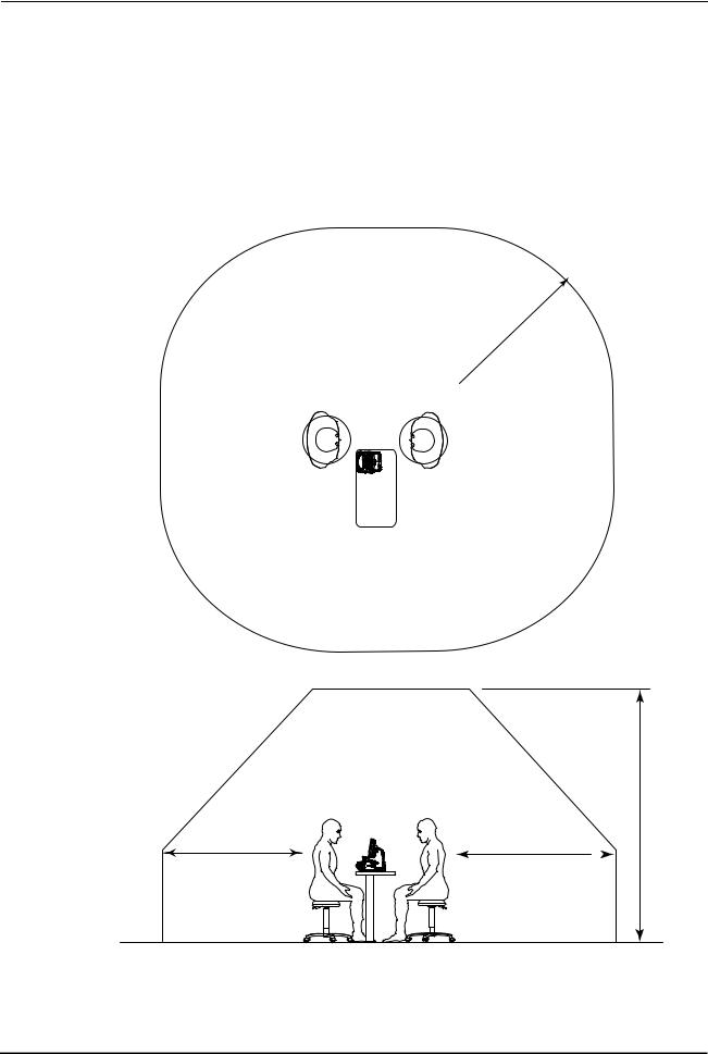
Patient environment
The patient environment is the volume of space in which contact can occur between the patient and any part of the device or between the patient and any other person(s) touching the device.
Use devices that comply with IEC6060-1 in the patient environment. If any device that does not comply with IEC 60601-1 is to be used, use an isolating transformer or common protective grounding.
Radius of 1.5 m
2.5 m
1.5 m |
1.5 m |
VIII
Table of Contents
1. BEFORE USE . . . . . . . . . . . . . . . . . . . . . . . . . . . . . . . . . . . 1
1.1 Outline of Device . . . . . . . . . . . . . . . . . . . . . . . . . . . . . . . . . . . . . . . . . . . . . . . . . . . . . . .1 1.2 Indications for Use . . . . . . . . . . . . . . . . . . . . . . . . . . . . . . . . . . . . . . . . . . . . . . . . . . . . .1 1.3 Principles . . . . . . . . . . . . . . . . . . . . . . . . . . . . . . . . . . . . . . . . . . . . . . . . . . . . . . . . . . . . . .2
1.4 Device Description . . . . . . . . . . . . . . . . . . . . . . . . . . . . . . . . . . . . . . . . . . . . . . . . . . . . .3 { Front view . . . . . . . . . . . . . . . . . . . . . . . . . . . . . . . . . . . . . . . . . . . . . . . . . . . . . .3 { Rear view. . . . . . . . . . . . . . . . . . . . . . . . . . . . . . . . . . . . . . . . . . . . . . . . . . . . . . .4
1.5 Screen Description . . . . . . . . . . . . . . . . . . . . . . . . . . . . . . . . . . . . . . . . . . . . . . . . . . . . .8 1.5.1 A-scan biometry screen . . . . . . . . . . . . . . . . . . . . . . . . . . . . . . . . . . . . . . . . . . . . . .8 1.5.2 IOL power calculation screen . . . . . . . . . . . . . . . . . . . . . . . . . . . . . . . . . . . . . . . . .11 1.5.3 A-scan biometry utility screen . . . . . . . . . . . . . . . . . . . . . . . . . . . . . . . . . . . . . . . . .13 1.5.4 B-scan imaging screen . . . . . . . . . . . . . . . . . . . . . . . . . . . . . . . . . . . . . . . . . . . . . .15 1.5.5 B-scan imaging utility screen . . . . . . . . . . . . . . . . . . . . . . . . . . . . . . . . . . . . . . . . .17 1.5.6 Pachymetry screen . . . . . . . . . . . . . . . . . . . . . . . . . . . . . . . . . . . . . . . . . . . . . . . . .19 1.5.7 Pachymetry utility screen . . . . . . . . . . . . . . . . . . . . . . . . . . . . . . . . . . . . . . . . . . . .21 1.5.8 Utility screen (1/2) . . . . . . . . . . . . . . . . . . . . . . . . . . . . . . . . . . . . . . . . . . . . . . . . . .23 1.5.9 Utility screen (2/2) . . . . . . . . . . . . . . . . . . . . . . . . . . . . . . . . . . . . . . . . . . . . . . . . . .25
1.6 Labels and Indications on the Device . . . . . . . . . . . . . . . . . . . . . . . . . . . . . . . . . . .26 1.7 Checking Contents . . . . . . . . . . . . . . . . . . . . . . . . . . . . . . . . . . . . . . . . . . . . . . . . . . . .28
2. OPERATING PROCEDURES . . . . . . . . . . . . . . . . . . . . . . 29
2.1 Operation flow
2.2 Device Setup. . . . . . . . . . . . . . . . . . . . . . . . . . . . . . . . . . . . . . . . . . . . . . . . . . . . . . . . . .32 2.2.1 Connecting power cord . . . . . . . . . . . . . . . . . . . . . . . . . . . . . . . . . . . . . . . . . . . . . .32 2.2.2 Connecting foot switch . . . . . . . . . . . . . . . . . . . . . . . . . . . . . . . . . . . . . . . . . . . . . .33 2.2.3 Attaching probe rest . . . . . . . . . . . . . . . . . . . . . . . . . . . . . . . . . . . . . . . . . . . . . . . .33
2.2.4 Connecting probe . . . . . . . . . . . . . . . . . . . . . . . . . . . . . . . . . . . . . . . . . . . . . . . . . .34 { A-scan probe . . . . . . . . . . . . . . . . . . . . . . . . . . . . . . . . . . . . . . . . . . . . . . . . . . .34 { Connecting B-scan probe . . . . . . . . . . . . . . . . . . . . . . . . . . . . . . . . . . . . . . . . .35 { Connecting Pachymetry probe. . . . . . . . . . . . . . . . . . . . . . . . . . . . . . . . . . . . . .35
2.2.5 Connecting Probe stand (optional) . . . . . . . . . . . . . . . . . . . . . . . . . . . . . . . . . . . . .36 { Attaching A-scan probe . . . . . . . . . . . . . . . . . . . . . . . . . . . . . . . . . . . . . . . . . . .36 { Attaching cable for fixation lamp . . . . . . . . . . . . . . . . . . . . . . . . . . . . . . . . . . . .36
2.3 Preparation . . . . . . . . . . . . . . . . . . . . . . . . . . . . . . . . . . . . . . . . . . . . . . . . . . . . . . . . . . .37 2.3.1 Adding new patient data . . . . . . . . . . . . . . . . . . . . . . . . . . . . . . . . . . . . . . . . . . . . .39 2.3.2 Setting physician data. . . . . . . . . . . . . . . . . . . . . . . . . . . . . . . . . . . . . . . . . . . . . . .41
2.4 A-scan Biometry. . . . . . . . . . . . . . . . . . . . . . . . . . . . . . . . . . . . . . . . . . . . . . . . . . . . . . .44 2.4.1 Basic operation of A-scan biometry . . . . . . . . . . . . . . . . . . . . . . . . . . . . . . . . . . . .44 2.4.2 Cautions in A-scan biometry . . . . . . . . . . . . . . . . . . . . . . . . . . . . . . . . . . . . . . . . . .50 2.4.3 Manual gate . . . . . . . . . . . . . . . . . . . . . . . . . . . . . . . . . . . . . . . . . . . . . . . . . . . . . .51 2.4.4 Calculation of IOL refractive power. . . . . . . . . . . . . . . . . . . . . . . . . . . . . . . . . . . . .53
IX

:
2.4.5 Comparison in DUAL screen . . . . . . . . . . . . . . . . . . . . . . . . . . . . . . . . . . . . . . . . . 56
2.4.6 Setting A-scan biometry utility . . . . . . . . . . . . . . . . . . . . . . . . . . . . . . . . . . . . . . . . 58 { Changing sonic velocity to calculate distance . . . . . . . . . . . . . . . . . . . . . . . . . . 58 { Setting IOL formula . . . . . . . . . . . . . . . . . . . . . . . . . . . . . . . . . . . . . . . . . . . . . . 60 { Setting normally used IOL . . . . . . . . . . . . . . . . . . . . . . . . . . . . . . . . . . . . . . . . . 61 { Setting fixation light ON/OFF. . . . . . . . . . . . . . . . . . . . . . . . . . . . . . . . . . . . . . . 62 { Setting print format . . . . . . . . . . . . . . . . . . . . . . . . . . . . . . . . . . . . . . . . . . . . . . 63 { Inputting IOL data . . . . . . . . . . . . . . . . . . . . . . . . . . . . . . . . . . . . . . . . . . . . . . . 64 { Calculating personal value . . . . . . . . . . . . . . . . . . . . . . . . . . . . . . . . . . . . . . . . 66 { Setting IOL power calculation formula in specified axial length range . . . . . . . 69
2.5 B-scan Imaging . . . . . . . . . . . . . . . . . . . . . . . . . . . . . . . . . . . . . . . . . . . . . . . . . . . . . . . 71 2.5.1 Basic operation of B-scan imaging. . . . . . . . . . . . . . . . . . . . . . . . . . . . . . . . . . . . . 71 2.5.2 Probe angle . . . . . . . . . . . . . . . . . . . . . . . . . . . . . . . . . . . . . . . . . . . . . . . . . . . . . . 73 2.5.3 Changing observation depth. . . . . . . . . . . . . . . . . . . . . . . . . . . . . . . . . . . . . . . . . . 73 2.5.4 Changing display range . . . . . . . . . . . . . . . . . . . . . . . . . . . . . . . . . . . . . . . . . . . . . 74 2.5.5 CV mode . . . . . . . . . . . . . . . . . . . . . . . . . . . . . . . . . . . . . . . . . . . . . . . . . . . . . . . . 76 2.5.6 Zoom . . . . . . . . . . . . . . . . . . . . . . . . . . . . . . . . . . . . . . . . . . . . . . . . . . . . . . . . . . . 77 2.5.7 Four image display . . . . . . . . . . . . . . . . . . . . . . . . . . . . . . . . . . . . . . . . . . . . . . . . . 79 2.5.8 Measuring area on B-scan imaging screen (Area screen) . . . . . . . . . . . . . . . . . . . 81 2.5.9 Measuring distance on B-scan image (Caliper screen) . . . . . . . . . . . . . . . . . . . . . 83 2.5.10 Moving image operation . . . . . . . . . . . . . . . . . . . . . . . . . . . . . . . . . . . . . . . . . . . . . 85
2.5.11 Setting B-scan imaging utility . . . . . . . . . . . . . . . . . . . . . . . . . . . . . . . . . . . . . . . . . 86 { Setting probe angle . . . . . . . . . . . . . . . . . . . . . . . . . . . . . . . . . . . . . . . . . . . . . . 86 { Setting scan depth. . . . . . . . . . . . . . . . . . . . . . . . . . . . . . . . . . . . . . . . . . . . . . . 87 { Setting scale color . . . . . . . . . . . . . . . . . . . . . . . . . . . . . . . . . . . . . . . . . . . . . . . 87 { Changing gain curve pattern . . . . . . . . . . . . . . . . . . . . . . . . . . . . . . . . . . . . . . . 88 { Setting Log scale range. . . . . . . . . . . . . . . . . . . . . . . . . . . . . . . . . . . . . . . . . . . 89 { Setting printer mode . . . . . . . . . . . . . . . . . . . . . . . . . . . . . . . . . . . . . . . . . . . . . 89 { Setting data format . . . . . . . . . . . . . . . . . . . . . . . . . . . . . . . . . . . . . . . . . . . . . . 90 { Other settings . . . . . . . . . . . . . . . . . . . . . . . . . . . . . . . . . . . . . . . . . . . . . . . . . . 90
2.6 Pachymetry. . . . . . . . . . . . . . . . . . . . . . . . . . . . . . . . . . . . . . . . . . . . . . . . . . . . . . . . . . . 91 2.6.1 Basic operation of pachymetry . . . . . . . . . . . . . . . . . . . . . . . . . . . . . . . . . . . . . . . . 91
2.6.2 Setting pachymetry utility . . . . . . . . . . . . . . . . . . . . . . . . . . . . . . . . . . . . . . . . . . . . 95 { Setting Pachymetry probe . . . . . . . . . . . . . . . . . . . . . . . . . . . . . . . . . . . . . . . . . 95 { Setting PRINT switch of foot switch . . . . . . . . . . . . . . . . . . . . . . . . . . . . . . . . . 96 { Setting printing of pachymetry results . . . . . . . . . . . . . . . . . . . . . . . . . . . . . . . . 96 { Setting corneal thickness sonic velocity to calculate distance . . . . . . . . . . . . . 97 { Setting map selected at device power-up . . . . . . . . . . . . . . . . . . . . . . . . . . . . . 97
2.7 UTILITY . . . . . . . . . . . . . . . . . . . . . . . . . . . . . . . . . . . . . . . . . . . . . . . . . . . . . . . . . . . . . . 98 2.7.1 Displaying Utility screen . . . . . . . . . . . . . . . . . . . . . . . . . . . . . . . . . . . . . . . . . . . . . 98
2.7.2 Setting Utility (1/2) . . . . . . . . . . . . . . . . . . . . . . . . . . . . . . . . . . . . . . . . . . . . . . . . 100 { Setting backlight . . . . . . . . . . . . . . . . . . . . . . . . . . . . . . . . . . . . . . . . . . . . . . . 100 { Setting Start Mode. . . . . . . . . . . . . . . . . . . . . . . . . . . . . . . . . . . . . . . . . . . . . . 100 { Setting Communication . . . . . . . . . . . . . . . . . . . . . . . . . . . . . . . . . . . . . . . . . . 101 { Setting date and time indication format . . . . . . . . . . . . . . . . . . . . . . . . . . . . . . 101 { Setting Auto OFF. . . . . . . . . . . . . . . . . . . . . . . . . . . . . . . . . . . . . . . . . . . . . . . 102 { Setting sound volume . . . . . . . . . . . . . . . . . . . . . . . . . . . . . . . . . . . . . . . . . . . 102 { Setting save mode. . . . . . . . . . . . . . . . . . . . . . . . . . . . . . . . . . . . . . . . . . . . . . 103
2.7.3 Setting Utility(2/2) . . . . . . . . . . . . . . . . . . . . . . . . . . . . . . . . . . . . . . . . . . . . . . . . . 107 { Adjusting touch screen . . . . . . . . . . . . . . . . . . . . . . . . . . . . . . . . . . . . . . . . . . 107 { Setting date and time . . . . . . . . . . . . . . . . . . . . . . . . . . . . . . . . . . . . . . . . . . . 107
X

:
{ Handling EEPROM parameters . . . . . . . . . . . . . . . . . . . . . . . . . . . . . . . . . . . 108 2.8 Completion of Operation. . . . . . . . . . . . . . . . . . . . . . . . . . . . . . . . . . . . . . . . . . . . . . 109
3. OPERATION WHEN PERIPHERAL DEVICES ARE CONNECTED . . 111
3.1 Connecting to Keratometer . . . . . . . . . . . . . . . . . . . . . . . . . . . . . . . . . . . . . . . . . . . 111 3.1.1 Outline . . . . . . . . . . . . . . . . . . . . . . . . . . . . . . . . . . . . . . . . . . . . . . . . . . . . . . . . . 111 3.1.2 Method of connection (example) . . . . . . . . . . . . . . . . . . . . . . . . . . . . . . . . . . . . . 111 3.1.3 Operating procedure. . . . . . . . . . . . . . . . . . . . . . . . . . . . . . . . . . . . . . . . . . . . . . . 112
3.2 Connecting to Video Printer. . . . . . . . . . . . . . . . . . . . . . . . . . . . . . . . . . . . . . . . . . . 112 3.3 Connecting to USB Port . . . . . . . . . . . . . . . . . . . . . . . . . . . . . . . . . . . . . . . . . . . . . . 113 3.4 Connecting to LAN Port . . . . . . . . . . . . . . . . . . . . . . . . . . . . . . . . . . . . . . . . . . . . . . 114
4. CHECKS . . . . . . . . . . . . . . . . . . . . . . . . . . . . . . . . . . . . . 117
4.1 Checks Before Use. . . . . . . . . . . . . . . . . . . . . . . . . . . . . . . . . . . . . . . . . . . . . . . . . . . 117 4.2 Usage of the Test Piece . . . . . . . . . . . . . . . . . . . . . . . . . . . . . . . . . . . . . . . . . . . . . . 118 4.2.1 Usage of test piece for A-scan biometry. . . . . . . . . . . . . . . . . . . . . . . . . . . . . . . . 118 4.2.2 Usage of test piece for pachymetry . . . . . . . . . . . . . . . . . . . . . . . . . . . . . . . . . . . 119
4.3 Check List . . . . . . . . . . . . . . . . . . . . . . . . . . . . . . . . . . . . . . . . . . . . . . . . . . . . . . . . . . . 121
5. MAINTENANCE . . . . . . . . . . . . . . . . . . . . . . . . . . . . . . . 123
5.1 Troubleshooting. . . . . . . . . . . . . . . . . . . . . . . . . . . . . . . . . . . . . . . . . . . . . . . . . . . . . . 123
5.2 Various error codes and Suggested Actions
5.3 Replacing Printer Paper
5.4 Replacing Fuses
5.5 Cleaning. . . . . . . . . . . . . . . . . . . . . . . . . . . . . . . . . . . . . . . . . . . . . . . . . . . . . . . . . . . . . 131 5.5.1 Cleaning cover . . . . . . . . . . . . . . . . . . . . . . . . . . . . . . . . . . . . . . . . . . . . . . . . . . . 131 5.5.2 Cleaning printer . . . . . . . . . . . . . . . . . . . . . . . . . . . . . . . . . . . . . . . . . . . . . . . . . . 131 5.5.3 Cleaning touch screen . . . . . . . . . . . . . . . . . . . . . . . . . . . . . . . . . . . . . . . . . . . . . 132
5.6 Maintenance of Ultrasound Probe . . . . . . . . . . . . . . . . . . . . . . . . . . . . . . . . . . . . . 133 5.6.1 Cleaning ultrasound probe . . . . . . . . . . . . . . . . . . . . . . . . . . . . . . . . . . . . . . . . . . 133 5.6.2 Disinfecting ultrasound probe. . . . . . . . . . . . . . . . . . . . . . . . . . . . . . . . . . . . . . . . 134 5.6.3 Sterilizing ultrasound probe . . . . . . . . . . . . . . . . . . . . . . . . . . . . . . . . . . . . . . . . . 135
5.7 List of Replacement Parts . . . . . . . . . . . . . . . . . . . . . . . . . . . . . . . . . . . . . . . . . . . . 136
6. SPECIFICATIONS AND CONFIGURATION . . . . . . . . . 137
6.1 Classifications . . . . . . . . . . . . . . . . . . . . . . . . . . . . . . . . . . . . . . . . . . . . . . . . . . . . . . . 137
XI

:
6.2 Specifications . . . . . . . . . . . . . . . . . . . . . . . . . . . . . . . . . . . . . . . . . . . . . . . . . . . . . . . . 138 6.2.1 A-scan biometry/IOL power calculation . . . . . . . . . . . . . . . . . . . . . . . . . . . . . . . . 138 6.2.2 B-scan imaging. . . . . . . . . . . . . . . . . . . . . . . . . . . . . . . . . . . . . . . . . . . . . . . . . . . 139 6.2.3 Pachymetry. . . . . . . . . . . . . . . . . . . . . . . . . . . . . . . . . . . . . . . . . . . . . . . . . . . . . . 139 6.2.4 Other functions . . . . . . . . . . . . . . . . . . . . . . . . . . . . . . . . . . . . . . . . . . . . . . . . . . . 139 6.2.5 Dimensions and weight . . . . . . . . . . . . . . . . . . . . . . . . . . . . . . . . . . . . . . . . . . . . 140 6.2.6 Environemntal conditions (during use) . . . . . . . . . . . . . . . . . . . . . . . . . . . . . . . . . 140 6.2.7 Environmental conditions (during storage and shipping) . . . . . . . . . . . . . . . . . . . 140 6.2.8 Composition of parts that come into contact with human body . . . . . . . . . . . . . . 140 6.2.9 Others. . . . . . . . . . . . . . . . . . . . . . . . . . . . . . . . . . . . . . . . . . . . . . . . . . . . . . . . . . 140
6.3 Configuration . . . . . . . . . . . . . . . . . . . . . . . . . . . . . . . . . . . . . . . . . . . . . . . . . . . . . . . . 141 6.3.1 Standard accessories. . . . . . . . . . . . . . . . . . . . . . . . . . . . . . . . . . . . . . . . . . . . . . 141 6.3.2 Optional accessories . . . . . . . . . . . . . . . . . . . . . . . . . . . . . . . . . . . . . . . . . . . . . . 141
7. IOL FORMULA . . . . . . . . . . . . . . . . . . . . . . . . . . . . . . . . 143
7.1 Outline of IOL Formula . . . . . . . . . . . . . . . . . . . . . . . . . . . . . . . . . . . . . . . . . . . . . . . 143
7.1.1 SRK Formula . . . . . . . . . . . . . . . . . . . . . . . . . . . . . . . . . . . . . . . . . . . . . . . . . . . . 143
7.1.2 SRK II Formula. . . . . . . . . . . . . . . . . . . . . . . . . . . . . . . . . . . . . . . . . . . . . . . . . . . 144
7.1.3 SRK/T Formula. . . . . . . . . . . . . . . . . . . . . . . . . . . . . . . . . . . . . . . . . . . . . . . . . . . 146
7.1.4 Binkhorst Formula . . . . . . . . . . . . . . . . . . . . . . . . . . . . . . . . . . . . . . . . . . . . . . . . 147
7.1.5 Hoffer Q Formula . . . . . . . . . . . . . . . . . . . . . . . . . . . . . . . . . . . . . . . . . . . . . . . . . 148
7.1.6 Holladay Formula . . . . . . . . . . . . . . . . . . . . . . . . . . . . . . . . . . . . . . . . . . . . . . . . . 149
8. EMC & Acoustic output. . . . . . . . . . . . . . . . . . . . . . . . . 151
8.1 EMC (ELECTROMAGNETIC COMPATIBILITY). . . . . . . . . . . . . . . . . . . . . . . . 151
8.2 Acoustic output reporting table(IEC 60601-2-37:2005) . . . . . . . . . . . . . . . . . . 156
8.2.1 A-scan probe . . . . . . . . . . . . . . . . . . . . . . . . . . . . . . . . . . . . . . . . . . . . . . . . . . . . 156 8.2.2 B-scan probe . . . . . . . . . . . . . . . . . . . . . . . . . . . . . . . . . . . . . . . . . . . . . . . . . . . . 157 8.2.3 45× angled probe with detachable tip. . . . . . . . . . . . . . . . . . . . . . . . . . . . . . . . . . 158 8.2.4 45× angled Probe . . . . . . . . . . . . . . . . . . . . . . . . . . . . . . . . . . . . . . . . . . . . . . . . . 159 8.2.5 Pachymetry probe . . . . . . . . . . . . . . . . . . . . . . . . . . . . . . . . . . . . . . . . . . . . . . . . 160 8.2.6 GLOBAL ACOUSTIC OUTPUT LIMITS . . . . . . . . . . . . . . . . . . . . . . . . . . . . . . . . 161
9. Glossary . . . . . . . . . . . . . . . . . . . . . . . . . . . . . . . . . . . . . 163
XII

1. BEFORE USE
1.1 Outline of Device
1
The NIDEK US-4000 Echoscan is an ultrasonic device to visualize the shape and properties of the eye interior and provide the image information to be used for diagnosis. It also measures the axial length and corneal thickness and provides the information to be used for diagnosis.
Axial length is one of the parameters used to determine the refractive power of an IOL prior to cataract surgery. By inputting the measured axial length with other parameters, the refractive power of an IOL can be calculated.
Corneal thickness is a necessary parameter when considering the clinical influence of surgery, drugs and contact lenses upon endothelium tissue. Pachymetry is now commonly performed prior to and after corneal refractive surgery using devices such as the excimer laser.
The US-4000 is comprised of a touch screen, main body with a built-in printer, an A-scan probe, a B- scan probe, a Pachymetry probe, and a foot switch. Items such as a video printer are also available as optional accessories.
1.2Indications for Use
The NIDEK US-4000 Echoscan is a medical device used for measuring the axial length, anterior chamber depth, corneal thickness, lens thickness, and vitreous body thickess, for calculating IOL power, and for observing the interior of the eye in B-scan imaging.
1

BEFORE USE: Principles
1.3Principles
Ultrasonic waves are the sound waves pitched above the range of human hearing whose frequency is 20,000 Hz or more. In the medical field, ultrasonic waves of frequencies between 1 and 15 MHz are applied, and these types of high sound waves have the following characteristics similar to light:
They have a high tendency to travel in a straight direction.
They have characteristics such as reflection and refraction at the boundaries of media which have different acoustic impedances.
(Acoustic impedance = Density of medium × Sonic velocity in the medium)
Special material is adopted to transmit and receive the ultrasonic pulses. Electrodes are placed on both sides of a thin piece of material, and the thickness of the material is changed by the fluctuation of voltage when a voltage is applied between them. The material vibrates with its inherent frequency when voltage is applied, and transmits the ultrasonic pulses. Conversely, when this material vibrates by the impact of the ultrasonic pulses, voltage of the same frequency is generated on both electrodes and it becomes possible to register the ultrasonic pulses as electrical signals. This phenomena is called the “Piezo effect”, and the converter, which electrically generates the ultrasound waves and changes them into voltage, is called a transducer.
In A-scan biometry, the ultrasonic pulse travels inside the eye when the probe is put on the eyeball. A portion of the pulses is reflected from the boundary of the cornea, anterior chamber, lens, vitreous body and retina, and their echoes are received at the same probe. The received echoes are converted to the electronic acoustic signals and indicated on the LCD as an amplitude. In addition, the time difference of each echo is measured and the size of each area of tissue (anterior chamber depth, lens thickness, vitreous body length and axial length) is calculated according to the time difference and known inherent sonic velocity through each kind of tissue.
In B-scan imaging, touching the mechanical sector scan probe with a built-in transducer to the eye emits the ultrasonic pulses that travel inside the eye. These pulses are reflected at boundaries of the cornea, anterior chamber, anterior chamber, crystalline lens, vitreous body, and retina. The reflected pulses (echoes) are received by the same mechanical sector scan probe to be converted to electrical signals. Then the amplitude of the electrical signals is converted to brightness to display the twodimensional static and dynamic images of the eye interior on the screen.
In pachymetry, the ultrasonic pulses are transmitted when the probe is put on the cornea. A part of the pulses is reflected at the front and rear surface of the cornea. When the probe receives the reflected echoes, the time difference of each echo is measured and the corneal thickness is calculated according to the time difference and known inherent sonic velocity through the cornea.
If the directions of the ultrasonic waves are not perpendicular to each boundary surface in both axial length and pachymetry, the echoes become weak and may not return to the probe. Therefore, it is very important to coincide the direction of the ultrasonic wave with the visual axis in order to achieve accurate measurement.
2

BEFORE USE: Device Description
1.4Device Description
{ Front view
1
 LCD touch screen
A 8.4-inch color LCD that is used as a touch screen for data input.
The LCD touch screen can be tilted for the operator's convenience.
 Knob 1
Used to change the TGC (Time Gain Control) or area of magnification.
 Knob 2
Used to change the gain or area of magnificaiton.
 Probe rest
Used to keep the probes when not in use.
 USB port
Used to connect the USB flash drive to save images, measurement data, and device parameters.
 Pilot lamp
Illuminates when power is supplied to the device.
3
BEFORE USE: Device Description
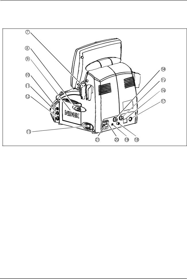
{ Rear view
|
 Probe holder
Place for keeping the probe.
 Cover open button
Pressed to open the printer cover.
 Printer cover
Used cover the internal printer with an automatic paper cutter. The printer cover is opened by pressing the Cover open button when replacing the printer paper.
 Probe connector (P)
Used to connect a Pachymetry probe (45° angled probe, 45° angled probe with detachable tip, or straight probe).
 Probe connector (BIO)
Used to connect the A-scan probe.
 Probe connector (B)
Used to connect the B-scan probe.
 Power switch
Pressed to turn ON and OFF power to the device.
4

BEFORE USE: Device Description
 External fixation lamp connector
When using the probe stand, power for its fixation lamp is supplied from this connector.
 Foot switch connector
The cable plug of the foot switch is connected here.
1
 LAN port
Used to connect the US-4000 with an external device (PC) using a LAN cable for data transmission.
 External communication connector
An RS-232C interface connector used to connect the US-4000 with an external device such as a PC for data transmission. When the US-4000 is connected to a NIDEK Keratometer, data obtained by the Keratometer can be imported to the US-4000.
 Video output terminal
Used to connect the video printer (optional) to print images.
 Remote connector
Used to connect the remote cable for the video printer (optional).
 Fuse holder
Contains fuses. The fuses are blown when overcurrent flows to the device.
 Inlet
Inlet
Used to connect the power cord.
5

BEFORE USE: Device Description
 Stylus
Used to manipulate the screen.
 B-scan probe
 A-scan probe
A solid probe with a built-in fixation lamp
 Pachymetry probe
45° Probe
A solid probe for pachymetry
45° probe (with detachable tip)
A solid probe for pachymetry with a detachable tip
Straight probe
A straight-type solid probe for pachymetry
FRAGILE
(4#)+.' 


(4#)+.' 


(4#)+.' 


6
BEFORE USE: Device Description
 Foot switch
Used for A-scan biometry, pachymetry, and B-scan imaging.
24+06
 Test piece
(for A-scan biometry)
(for pachymetry)
1
For 45° probe |
For straight probe |
 Printer paper (3 rolls)
 Ultrasound gel
Applied to the eyelid for B-scan imaging.
 Dust cover
7

BEFORE USE: Screen Description
1.5Screen Description
1.5.1A-scan biometry screen
|
|
 Patient switch
Pressed to register patient information and display the physician's name and the patient ID.
 Measurement value
Displays axial length, anterior chamber depth, and lens thickness.
 Mode switch
Pressed to display the desired screen among the A-scan biometry, B-scan imaging, and Pachymetry screens.
 Date and time switch
Displays the current date and time. Pressed to display the A-scan biometry utility screen.
 EYE TYPE switch
Pressed to select the type of the eye to be measured.
•Phakic: Phakic Eye
The axial length is converted from the average sonic velocity. Then the anterior chamber depth and the lens thickness are converted from their respective sonic velocities.
8

BEFORE USE: Screen Description
•Phakic2: Phakic Eye
The axial length is calculated by adding the anterior chamber depth, lens thickness, and vitreous body length that are converted from their respective sonic velocities.
•APhakic: APhakic Eye
•IOL: Pseudophakic Eye
1
MODE switch |
Pressed to change the measurement method.
Auto: The measurement is completed when acceptable measurement conditions continue for a determined duration.
Speedy: The measurement is completed automatically and the acceptability of the waveform is determined by the device.
Manual: The measurement is performed by depressing the foot switch.
 DENSE CAT switch
OFF: A normal eyes are measured.
ON: An eye with a dense cataract are measured.
(The parameters are changed as follows: THRESHOLD to "Flat Low," gain to 100%, Axial Velocity to 1548 m/s and Lens Velocity to 1629 m/s. These parameters can be changed in the Utility screen.)
* This switch is not displayed when the Eye Type is Aphakic or IOL.
 THRESHOLD switch
Pressed to change the programmed threshold which automatically determines the measurement value of each intraocular part. Each time this switch is pressed, the threshold indication below the switch changes among “Normal,” “Low,” and “Flat Low.”
*Generally set to “Normal”. If the measurement cannot be performed with an eye with mature cataract even by increasing the gain, the measuerment may become possible by changing the threshold to “Low” or “Flat Low.”
 Measurement data list indication area
Up to 10 measurement values (three times of three measurement values (nine times in total) in Speedy mode) for axial length and each intraocular part are indicated. Whenever the measurement data is obtained, the average (Avg) and standard deviation (SD) in the list are calculated and indicated.
*The measurement value of each intraocular part varies according to the selected Eye Type as shown in the table below.
|
|
Anterior |
Lens |
Vitreous body |
|
Eye type |
Axial length |
chamber |
|||
thickness |
length |
||||
|
|
depth |
|||
|
|
|
|
||
|
|
|
|
|
|
Phakic |
O |
O |
O |
O |
|
|
|
|
|
|
|
Phakic2 |
O |
O |
O |
O |
|
|
|
|
|
|
|
APhakic |
O |
- |
- |
- |
|
|
|
|
|
|
|
IOL |
O |
O |
- |
O |
|
|
|
|
|
|
 Gate display
The specified gate can be moved using Knob 1.
9

BEFORE USE: Screen Description
 Gain display
Displays the gain during the A-scan biometry.
The gain is adjusted with Knob 2.
 PRINT switch
Pressed to print the data being displayed.
 Data save switch
Pressed to save data.
 CLEAR switch
Pressed to delete the measurement data in the measurement data list. Once the data is deleted, it cannot be restored.
 DUAL switch
Pressed to display the DUAL window where data (waveform and measurement data) is read from the internal memory, USB flash drive, or the PC.
 DELETE switch
Pressed to delete the measurement data in the list.
To delete data, highlight the data to delete by pressing it with the finger or stylus, then press the DELETE switch. When the DELETE switch is pressed, it changes to the RECALL switch which restores the deleted data.
 SELECT switch
Pressed to decide the measurement data to be used for IOL power calculation.
When this switch is pressed, the "*" mark is attached to the selected data which is to be used for IOL power calculation.
If this function is not used, the average data is used for IOL power calculation.
*The A-scan biometry data to be used for IOL power calculation can also be input in the IOL power calculation screen.
 BIO/IOL Select switch
Pressed to switch the A-scan biometry screen and IOL power calculation screen.
 Gate display switch
Pressed to toggle display of each gate between ON and OFF.
 Gate switch
Pressed to select the desired gate and enable or disable the manual gate function for each gate. Four gate types are available: Cornea, Lens-F (anterior), Lens-B (posterior), and Retina.
 FREEZE/LIVE switch
Pressed to start or stop the A-scan biometry.
 OD/OS switch
Pressed to change the eye to be measured.
10
BEFORE USE: Screen Description
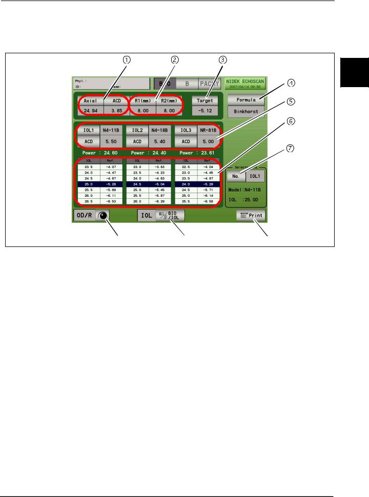
1.5.2IOL power calculation screen
|
|
|
|
|
1


 A-scan biometry data
A-scan biometry data is automatically input. The data also can be input manually.
 Keratometer reading
Corneal curvature radius (mm) and/or corneal refractive power (D) are input.
 Target
Target postoperative refractive power is input.
 Formula switch
Pressed to select the desired IOL formula.
 IOL Select switch
Pressed to select IOLs to be used.
 IOL power calculation result table
Displays the IOL power calculation results when the values required for the calculation are input. For each IOLs, IOL powers that are closest to the calculation result and the expected postoperative refractive power with those IOL powers are displayed. The highlighted row shows the values closest to the target postoperative refractive power.
 IOL Select switch
Pressed to select the IOL to be used for surgery from IOL1 to IOL3.
The selected IOL is highlighted (white characters on a dark background) on the calculation result printout.
11

BEFORE USE: Screen Description
 Print switch
Pressed to print the calculation results.
 BIO/IOL Select switch
Pressed to switch the A-scan biometry and IOL power calculation screens.
 OD/OS switch
Pressed to switch the eye to be measured.
12
BEFORE USE: Screen Description
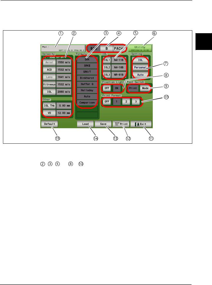
1.5.3A-scan biometry utility screen
|
|
|
1
|
|
 Physician switch
Pressed to select the physician (1 to 5) and register the Physician data.
Conditions set in |
, |
, |
and |
to |
can be set for each physician. |
 Velocity input area
Pressing each switch displays the ten-key window and the sonic velocity to calculate distance can be input. Pressing the Default switch resets all the values to the default values.
 Formula area
The IOL formula to be used in the IOL power calculation is selected. (Multiple formulas can be selected.)
 Mode switches
Pressed to display the desired screen among the A-scan biometry, B-scan imaging, and Pachymetry utility screens.
 IOL area
The IOLs used for IOL1, 2, and 3 are selected.
 Utility switch
Pressed to display the Utility screen.
13

BEFORE USE: Screen Description
 Setting switches
IOL switch: Pressed to register IOLs.
Personal switch: Pressed to calculate the Personal value.
Auto switch: Pressed to perform calculation for the selected IOL within the specified axial length.
 Fixation Light switches
Pressed to toggle the fixation light in the A-scan probe between ON and OFF.
 Foot Switch switches
Pressed to toggle the function of the PRINT switch between printing and changing of the measurement mode.
 Print Format switches
Pressed to select the desired print format.
 Exit switch
Pressed to return to the A-scan biometry screen.
 PRINT switch
Pressed to print the A-scan biometry utility settings.
 Save switch
Pressed to save the A-scan biometry utility settings.
 Load switch
Pressed to return the A-scan biometry utility settings to the saved ones.
 Default switch
Pressed to return the A-scan biometry utility settings to the default.
14

BEFORE USE: Screen Description
1.5.4B-scan imaging screen


1
|
 Patient switch
Pressed to register patient information and display the physician's name and the patient ID and name.
 Mode switches
Pressed to display the desired screen among the A-scan biometry, B-scan imaging, and Pachymetry screens.
 Date and time switch
Displays the current date and time. Pressed to display the B-scan imaging utility screen.
 Probe angle switch
Displays the angle of the probe on the eye to be measured. The default value is "90°" and each pressing of the switch increases the angle by 45°.
 Observation depth switch
Pressed to switch the observation depth (from the tip of the probe).
Norm (35 mm) Long (50 mm)
 Display range switch
Pressed to change the display range.
Enabled when the gain curve pattern is set to "Log." The display range can be selected among 10, 20, 30, 40, and 50 dB.
15

BEFORE USE: Screen Description
 CV (Cross Vector) mode switches
The triangle switches are pressed to move the cross ventor line. The CV switch in the center is pressed to toggle the CV mode between ON and OFF.
 Zoom switch
Pressed to magnify the image on the screen to "×2.5" or "×5."
In the magificination screen, the image navigator "Zoom Navi" is displayed.
 Area/Caliper screen switch
Pressed to display the Area/Caliper screen.
 Four-image display switch
Pressed to display the Four-image display screen.
The Four-image display screen cannot be displayed if no data is saved in the internal memory.
 Print switch
Pressed to print the data being displayed.
 Data save switch
Pressed to save the measurement data to an external (USB flash drive or PC) or the internal memory.
 Data read switch
Pressed to display the FILE window and read the data from the stored location.
 Moving image operation switches
Pressed to play the moving image of about 20 seconds (200 frames) just before the FREEZE switch is pressed.
The saved moving image is deleted in the following cases:
When the LIVE condition is resumed When power to the device is turned off When a New Patient is added
 LIVE/FREEZE switch
Pressed to start (LIVE) or stop (FREEZE) the measurement. The same operation can be performed with the foot switch.
 OD/OS switch
Pressed to switch the eye to be measured.
 Measurement condition display
Displays the B-scan imaging conditions.
 B-scan image display
Displays the B-scan image and cross-vector line.
16
 Loading...