


NIDEK
LASER DIODE PHOTOCOAGULATOR
Model DC-3300
SERVICE MANUAL
December, 2004 XDC7**RDA001E/E Total 50 pages

NIDEK CO., LTD. |
: 34-14, Maehama, Hiroishi-cho, Gamagori, Aichi 443-0038, Japan |
(Manufacturer) |
Telephone: (0533) 67-6611 |
|
Facsimile: (0533) 67-6610 |
NIDEK CO., LTD |
: 6th Floor, Takahashi Bldg., No.2, 3-chome, Kanda-jinboucho |
(Tokyo Office) |
Chiyoda-ku, Tokyo 101-0051, Japan |
|
Telephone: (03) 3288-0571 |
|
Facsimile: (03) 3288-0570 |
|
Telex: 2226647 NIDEK J |
NIDEK INCORPORATED |
: 47651 Westinghouse Drive, Fremont, California 94539, U. S. A. |
(United States Agent) |
Telephone: (510) 226-5700 |
|
Facsimile: (510) 226-5750 |
NIDEK SOCIETE ANONYME |
: Europarc 13, rue Auguste Perret, 94042 CRETEIL, France |
(Authorized Representative) |
Telephone: (01) 49 80 97 97 |
|
Facsimile: (01) 49 80 32 08 |

Table of Contents
§1 CAUTIONS FOR MAINTENANCE |
Page |
||
1-1 |
|||
§2 TROUBLESHOOTING .............................................................................................. |
2-1 |
||
§3 SUB-TROUBLESHOOTING ..................................................................................... |
3-1 |
||
3.1 The system does not start at all ................................................................................ |
3-1 |
||
3.2 |
Fan does not work .................................................................................................... |
3-3 |
|
3.3 |
Indication on the front panel is not correct............................................................... |
3-3 |
|
3.4 |
Err. 20 appears .......................................................................................................... |
3-4 |
|
3.5 |
Setting of coagulation power output cannot be changed correctly ........................... |
3-5 |
|
3.6 |
Setting of coagulation time cannot be changed correctly ......................................... |
3-5 |
|
3.7 |
Repeat mode cannot be set correctly ........................................................................ |
3-5 |
|
3.8 |
Brightness of aiming beam cannot be changed correctly ......................................... |
3-5 |
|
3.9 Aiming beam cannot be seen .................................................................................... |
3-5 |
||
3.10 |
Err. 3 appears .......................................................................................................... |
3-6 |
|
3.11 READY indication does not light up by pressing the STATUS switch .................. |
3-7 |
||
3.12 |
STAND BY indication does not light up by pressing the STATUS switch ............ |
3-7 |
|
3.13 |
Counter cannot be reset .......................................................................................... |
3-7 |
|
3.14 |
Laser beam cannot be emitted ................................................................................ |
3-7 |
|
3.15 |
Err. 1 appears .......................................................................................................... |
3-8 |
|
3.16 |
Err. 10 appears ........................................................................................................ |
3-9 |
|
3.17 |
Err. 12 appears ........................................................................................................ |
3-9 |
|
3.18 |
Err. 13 appears ........................................................................................................ |
3-9 |
|
3.19 |
Err. 15 appears ........................................................................................................ |
3-9 |
|
3.20 |
Err. 53 appears ...................................................................................................... |
3-10 |
|
3.21 |
Err. 54 appears ...................................................................................................... |
3-10 |
|
3.22 INTLK2.7 appears ................................................................................................ |
3-11 |
||
3.23 INTLK4.7 appears ................................................................................................ |
3-12 |
||
3.24 Actual power output is low................................................................................... |
3-13 |
||
3.25 Actual power output is high ................................................................................. |
3-14 |
||
3.26 EMERGENCY OFF button does not work .......................................................... |
3-14 |
||
3.27 |
Err. 4 appears ........................................................................................................ |
3-14 |
|
§4 REPLACEMENT ......................................................................................................... |
4-1 |
||
4.1 |
Replacement of fuses ............................................................................................... |
4-1 |
|
4.2 |
Replacement of upper cover ..................................................................................... |
4-1 |
|
4.3 |
Replacement of lower cover ..................................................................................... |
4-2 |
|
4.4 |
Replacement of front cover ...................................................................................... |
4-2 |
|
4.5 |
Replacement of PS1 ................................................................................................. |
4-3 |
|
4.6 Replacement of BA05 (SW BOARD)...................................................................... |
4-3 |
||
4.7 Replacement of BA02 (LASER CONTROL BOARD) ........................................... |
4-3 |
||

§5
§6
|
|
Page |
4.8 Replacement of BA01 (MASTER BOARD) ........................................................... |
4-3 |
|
4.9 |
Replacement of Key control switch ......................................................................... |
4-4 |
4.10 Replacement of EMERGENCY OFF button ......................................................... |
4-4 |
|
4.11 Replacement of fan ................................................................................................. |
4-5 |
|
4.12 Replacement of BA03 (DISPLAY BOARD) ......................................................... |
4-5 |
|
4.13 Replacement of BA09 (SENSOR BOARD) of safety shutter................................ |
4-6 |
|
4.14 Replacement of BA09 (SENSOR BOARD) of coagulation shutter ...................... |
4-6 |
|
4.15 Replacement of microswitch of CONDENSOR ASSY ......................................... |
4-7 |
|
ADJUSTMENT ............................................................................................................ |
5-1 |
|
5.1 |
Optical adjustment ................................................................................................... |
5-1 |
|
5.1.1 Adjustment of optical axis of aiming beam .................................................... |
5-1 |
|
5.1.2 Adjustment of fiber alignment ........................................................................ |
5-2 |
|
5.1.3 Operation check of coagulation shutter sensor ............................................... |
5-3 |
|
5.1.4 Operation check of safety shutter sensor......................................................... |
5-3 |
5.2 |
Electrical adjustment ................................................................................................ |
5-4 |
|
5.2.1 Setting of LASER CONTROL BOARD (BA02) ............................................ |
5-4 |
|
5.2.2 Setting of DISPLAY BOARD (BA03) ............................................................ |
5-4 |
|
5.2.3 Input voltage check ......................................................................................... |
5-4 |
|
5.2.4 Adjustment of T.E.COOLER .......................................................................... |
5-5 |
|
5.2.5 COAG STANDBY check ................................................................................ |
5-5 |
|
5.2.6 D/A converter signal check ............................................................................. |
5-5 |
|
5.2.7 Current limit check.......................................................................................... |
5-5 |
5.3 |
General adjustment ................................................................................................... |
5-6 |
|
5.3.1Current limit adjustment .................................................................................. |
5-6 |
|
5.3.2 Adjustment of 1/4 wavelength constant position ............................................ |
5-6 |
|
5.3.3 Overshoot check .............................................................................................. |
5-6 |
|
5.3.4 Light control adjustment ................................................................................. |
5-6 |
|
5.3.5 Adjustment of each monitor ............................................................................ |
5-7 |
|
5.3.6 Adjustment of overpower ................................................................................ |
5-7 |
|
5.3.7 Adjustment of each delivery unit .................................................................... |
5-8 |
|
5.3.8 Adjustment of aiming beam ............................................................................ |
5-9 |
|
5.3.9 Adjustment of COAG TIME ......................................................................... |
5-10 |
|
5.3.10 Adjustment of REPEAT TIME .................................................................... |
5-10 |
REFERENCES ............................................................................................................. |
6-1 |
|
6.1 Wiring diagram (CABLE ASSY) ............................................................................. |
6-1 |
|
6.2 |
Tools ......................................................................................................................... |
6-2 |
6.3 |
Error code list ........................................................................................................... |
6-3 |
6.4 |
Interlock code list ..................................................................................................... |
6-3 |
6.5 |
DIP SW function list ................................................................................................ |
6-4 |
6.6 |
System parameter ..................................................................................................... |
6-4 |
|
6.6.1 Change/Setting method of value of parameter ................................................ |
6-4 |
|
6.6.2 System parameter list ...................................................................................... |
6-5 |

§1 CAUTIONS FOR MAINTENANCE
•Be sure to use this manual after reading and understanding the operator’s manual for the DC3300 thoroughly.
•Only properly trained service technicians can repair the system.
•During the repair, any indications are necessary to prohibit the unauthorized persons from entering the working area and to prevent the accidents such as emitting laser to personnel.
•Wear protective goggles when the laser is emitted.
•Never look directory into the laser diode beam even if wearing goggles.
•Never point the probe tip or the laser aperture to personnel.
•Apply the lock-tight to the screws when they are loosened and tightened again.
•For maintenance, turn OFF the power and disconnect the socket from the wall-outlet unless this manual specifies “Turn ON the power”.
•In case that the abnormal smell and/or noise is produced from DC-3300, turn the key switch to the OFF position immediately or press the EMERGENCY OFF button.
•When performing a maintenance with the covers (upper, lower or front cover) removed, take the following measures in order to protect the laser diodes from static electricity.
•Spread a conductive mat on the workbench, then connect the earth wire from the mat to a ground.
•Field service representative should put a wrist strap on his/her wrist, and connect the earth wire from it.
•Earth the measuring instruments such as oscilloscope and laser power meter as well.
•Use a soldering iron provided with an earth wire.
•Before using a tool, always touch the metal part to the conductive mat.
•Connect an earth wire to the terminal on the rear panel as well.
•Specifications and design are subject to change without notice for improvement. Since the Technical Bulletin will be released every time significant changes are made to the system, refer to the Technical Bulletin together with this manual.

1 - 2

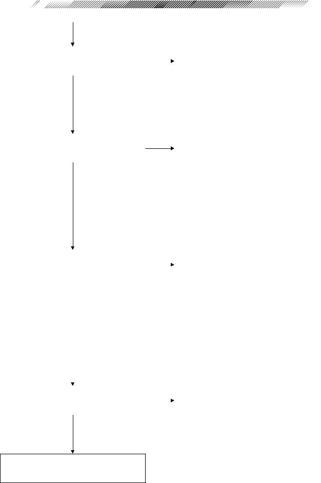
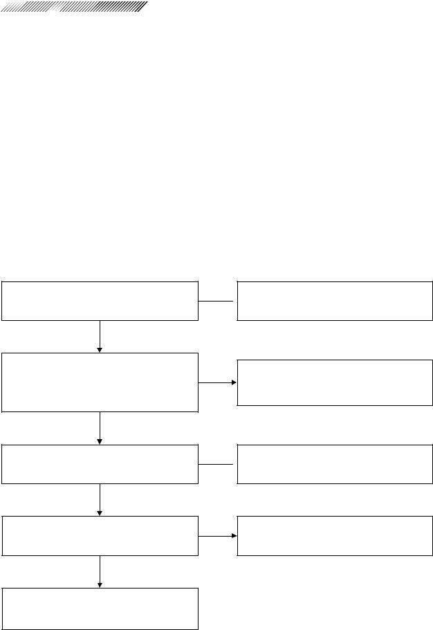
§2 TROUBLESHOOTING
Turn ON the key control switch. Does the system start correctly?
Is the system put in the initial condition correctly after count down?
Can the setting of coagulation power output be changed correctly?
Can the setting of coagulation time be changed correctly?
Can the repeat mode be set correctly?
Can the brightness of aiming beam be changed correctly?
Does READY light up by pressing the STATUS switch?
3.1The system does not start at all
3.2Fan does not work
 3.3 Indication on the front panel is not correct
3.27 Err. 4 appears
 3.4 Err. 20 appears
3.5Setting of coagulation power output cannot be changed correctly
3.6Setting of coagulation time cannot be changed correctly
 3.7 Repeat mode cannot be reset correctly
3.8Brightness of aiming beam cannot be changed correctly
3.9Aiming beam cannot be seen
3.10Err. 3 appears
3.11READY indication does not light up by pressing the STATUS switch
2 - 2
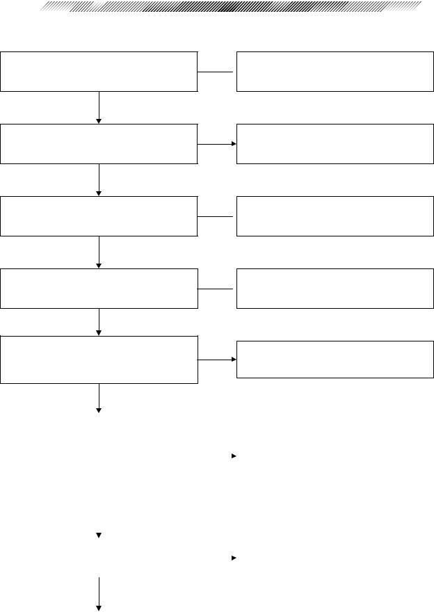
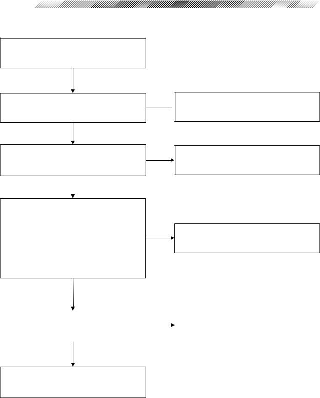
Does STAND BY light up by pressing the |
|
3.12 STAND BY does not light up by |
|
STATUS switch? |
|
|
pressing the STATUS switch |
|
|
|
|
Is the Application COUNTER reset by |
|
3.13 Counter cannot be reset |
pressing the Counter Reset switch? |
|
|
|
|
|
|
|
|
|
|
|
|
|
|
|
3.14 |
Laser beam cannot be emitted |
|
|
|
|
|
|||
|
|
|
|
3.15 |
Err. 1 appears |
|
|
|
|
|
3.16 |
Err. 10 appears |
|
|
|
|
|
3.17 |
Err. 12 appears |
|
|
|
|
|
3.18 |
Err. 13 appears |
|
Is the laser diode beam emitted correctly |
||||||
|
3.19 Err. 15 appears |
|||||
by pressing the foot switch? |
|
|
3.20 Err. 53 appears |
|||
|
|
|
|
3.21 |
Err. 54 appears |
|
|
|
|||||
|
|
|
|
3.22 |
INTLK2.7 appears |
|
|
|
|
|
3.23 |
INTLK4.7 appears |
|
|
|
|
|
3.24 |
Actual power output is low |
|
|
|
|
|
3.25 |
Actual power output is high |
|
|
|
|
|
|
|
|
|
|
|
|
|
||
|
|
|
|
|
|
|
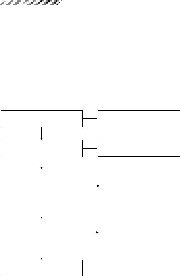
Does the system stop by pressing the |
|
3.26 EMERGENCY OFF button does not |
|
EMERGENCY OFF button? |
|
|
work |
|
|
|
|
END
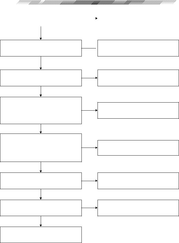
§3 SUB-TROUBLESHOOTING
3.1 The system does not start at all
Is the voltage of the outlet proper?
Are the fuses normal?
Are connectors P901, P902 and P903 on PS1 (switching power supply) connected correctly?
Are connectors P501, P502, P503, P504 and P505 on BA05 connected correctly?
Is the voltage between 2nd and 3rd pins of the connector J901 on PS1 (switching power supply) proper?
 Obtain the proper line voltage.
Replace the fuses with the new ones (see 4.1).
 Correct the connection.
 Correct the connection.
Failure of EA20.
Repair or replace it with the new one.
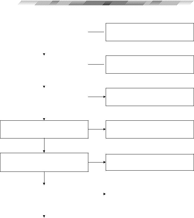
Is the voltage between 1st pin of the |
|
|
|
|
connector J902 and 1st pin of J903 on PS1 |
|
|
|
|
(switching power supply) +12V? |
|
Failure of PS1 (switching power supply). |
||
Is the voltage between 2nd pin of J902 and |
|
|
Replace it with the new one (see 4.5). |
|
2nd pin of J903 on PS1 (switching power |
|
|
|
|
supply) +12V? |
|
|
|
|
|
|
|
|
|
|
|
|
|
|
|
|
|
|
|
|
|
|
|
|
Is the voltage between 1st and 2nd pins of |
|
Failure of EA21. |
||
the connector P505, and, P501 and P503 on |
|
|
Repair or replace it with the new one. |
|
|
|
|||
BA05, +12V? |
|
|
||
|
|
|
||
3 - 2
Is the voltage between connectors P502 |
|
Failure of BA05. |
|
and P504 on BA05 +12V? |
|
|
Replace it with the new one (see 4.6). |
|
|
|
|
Is the connector P201 on BA02 connected correctly?
Is the voltage between 1st and 2nd pins of the connector J201 on BA02 +12V?
Is the voltage between 1st and 2nd pins of the connector J209 on BA02 +12V?
Is the voltage between 3rd and 4th pins of the connector J209 on BA02 +5V?
Is the voltage between 1st and 3rd pins of the connector J113 on BA01 +12V?
Is the voltage between 1st and 2nd pins of the connector J110 on BA01 +5V?
Is the key control switch correct?
Is the EMERGENCY OFF button is correct?
 Correct the connection.
Failure of EA22.
Repair or replace it with the new one.
Failure of BA02.
Replace it with the new one (see 4.7).
Failure of EA13.
Repair or replace it with the new one.
Failure of the key control switch. Replace it with the new one (see 4.9).
Failure of the EMERGENCY OFF button. Replace it with the new one (see 4.10).
Failure of BA01.
Replace it with the new one (see 4.8).
3.2 Fan does not work
Is the connector P207 on BA02 connected correctly?
Is the voltage of connector P207 on BA02 correct?
Connector P207
1-2: DC12V
Failure of the fan.
Replace it with the new one (see 4.11).


 3 - 3
3 - 3
 Correct the connection.
Failure of BA02.
Replace it with the new one (see 4.7).
3.3 Indication on the front panel is not correct
Is the flexible flat cable between the |
|
|
|
|
|
Correct the connection. |
|||
connector J301 on BA03 and the connector |
|
|||
J106 on BA01 connected correctly? |
|
|
|
|
|
|
|
|
|
|
|
|
|
|
|
|
|
|
|
Failure of BA03. |
|
|
|
|
Replace it with the new one (see 4.12). |
|
|
|
|
|
|
|
|
|
|
|
|
|
|
|
|
|
|
|
|
|
|
|
|
Is the indication on the front panel correct? |
|
|
Failure of BA01. |
|
|
|
Replace it with the new one (see 4.8). |
||
|
|
|
|
|
|
|
|
|
|
3 - 4
3.4 Err. 20 appears
Is the connector P901 on PS1 connected |
|
|
correctly? |
|
|
|
|
|
|
|
|
|
|
|
|
|
|
Is the connector P201 on BA02 connected |
|
|
correctly? |
|
|
|
|
|
|
|
|
|
|
|
|
|
|
Is the voltage output to TP9 on BA02 other |
|
|
than 0V? |
|
|
|
|
|
|
|
|
|
|
|
 Correct the connection.
 Correct the connection.
Failure of the cable EA08. Replace it with the new one.
Is the voltage output to TP9 on BA02 other than 0V?
Is the trouble resolved?
Failure of the laser head.
Send the system back to NIDEK.
Failure of BA02.
Replace it with the new one (see 4.7).
Is the trouble resolved? |
|
Failure of BA01. |
||
|
|
Replace it with the new one (see 4.8). |
||
|
|
|
|
|
|
|
|
|
|
|
|
|
|
|
|
|
|
|
|
|
|
|
|
|
Adjust T.E.COOLER. |
|
|
|
|
|
|
|
|
|


 3 - 5
3 - 5
3.5Setting of coagulation power output cannot be changed correctly
Perform as described in 3.3.
3.6 Setting of coagulation time cannot be changed correctly
Perform as described in 3.3.
3.7 Repeat mode cannot be set correctly
Perform as described in 3.3.
3.8 Brightness of aiming beam cannot be changed correctly
Perform as described in 3.3.
3.9 Aiming beam cannot be seen
Is the connector P114 on BA01 connected correctly?
Is the voltage between TP12 and A. GND on BA01 +1.2V or less?
Is the aiming beam emitted from the AIMING ASSY?
Does the safety shutter ASSY block the aiming laser optical path?
Can the aiming beam be seen by turning VR1 on BA01 clockwise?
 Correct the connection.
Failure of aiming laser.
Replace EA04 with the new one.
 Adjust the safety shutter.
Failure of BA01.
Replace it with the new one (see 4.8).
Misalignment of the optical axis of the aiming beam. Send the system back to NIDEK.
3 - 6
3.10 Err. 3 appears
Release the interlock and error.
Is the connector P103 on BA01 connected correctly?
Is the voltage between 1st-2nd, 3rd-5th and 6th-5th pins of the connector J103 on BA01 +12V?

Is the voltage between 4th and 5th pins of the connector J103 on BA01 +5V, when the shutter plate blocks the laser optical path?
Is the voltage between these points 0V, when the shutter plate does not block the laser optical path?
 Correct the connection.
Failure of BA01.
Replace it with the new one (see 4.8).
Failure of BA09 of EA02.
Replace it with the new one (see 4.13).
|
|
|
|
|
|
|
|
Is the safety shutter placed on the sensor |
|
Adjust the operation of the safety shutter. |
|
|
|
||
detection unit? |
|
|
|
|
|
|
|
|
|
|
|
|
|
|
|
Failure of BA01.
Replace it with the new one (see 4.8).


 3 - 7
3 - 7
3.11READY indication does not light up by pressing the
STATUS switch
Perform as described in 3.5.
3.12STAND BY indication does not light up by pressing the STATUS switch
Perform as described in 3.5.
3.13Counter cannot be reset
Perform as described in 3.5.
3.14Laser beam cannot be emitted
Is the connector P905 on the foot switch connected correctly?
Is the voltage between 7th and 10th pins of the connector J113 on BA01 +12V?
 Correct the connection.
Failure of BA01.
 Replace it with the new one (see 4.8).
|
|
|
|
|
|
|
|
|
|
|
|
|
|
|
|
||
|
|
|
|
|
|
|||
Is there continuity between these points on |
|
|
|
|
|
|||
EA13? |
|
|
|
|
|
|
|
|
|
|
|
|
|
|
Repair the broken part of EA13 or replace |
||
7th pin of P113 |
- 1st pin of J905 |
|
|
|||||
8th pin of P113 |
- 2nd pin of J905 |
|
|
|
|
it with the new one. |
||
9th pin of P113 |
- 3rd pin of J905 |
|
|
|
|
|
||
|
|
|
|
|
||||
10th pin of P113 - 4th pin of J905 |
|
|
|
|
|
|||
|
|
|
|
|
|
|
|
|
|
|
|
|
|
|
|
||
|
|
|
|
|
|
|||
Is the voltage between 8th-10th and 9th- |
|
|
|
|
|
|||
|
Failure of the foot switch. |
|||||||
10th pins of the connector J113 on BA01 |
||||||||
|
|
|
Replace it with the new one. |
|||||
+5V when the foot switch is pressed? |
|
|
|
|||||
|
|
|
|
|
||||
|
|
|
|
|
|
|
|
|
|
|
|
|
|
|
|
|
|
|
|
|
|
|
|
|
|
|
Failure of BA01.
Repair it with the new one (see 4.8).
 Loading...