


GYC-1000
NIDEK
GREEN LASER PHOTOCOAGULATOR
Model GYC-1000
SERVICE MANUAL
January 22, 2004
Pages in total: 68
XGYC4*RDA001A/E

This page is intentionally vacant.

Table of Contents
§
1 INTRODUCTION ......................................................................................................... 1-1
§
2 SAFETY ......................................................................................................................... 2-1
2.1General precautions ..................................................................................................... 2-1
2.2 Cautions in maintenance ..............................................................................................2-1
2.3 Cautions in adjustment ................................................................................................ 2-2
§
3 TROUBLESHOOTING ............................................................................................... 3-1
§
4 SUB-TROUBLESHOOTING ...................................................................................... 4-1
4.1The LINE indicator does not light up. ...........................................................................4-1
4.2 The fan does not work. ...............................................................................................4-1
4.3 INTERLOCK 6.3 appears......................................................................................... 4-2
4.4 Error 1 appears. .........................................................................................................4-2
4.5 Error 3 appears. .........................................................................................................4-3
4.6 Error 13 appears. .......................................................................................................4-3
4.7 Error 20 appears. .......................................................................................................4-4
4.8 Error 21 appears. .......................................................................................................4-4
4.9 Error 54 appears. .......................................................................................................4-5
4.10 Any error in the 90s appears. .................................................................................... 4-5
4.11 INTERLOCK 4.7 appears. ......................................................................................4-6
4.12 The coagulation power cannot be changed. ............................................................... 4-6
4.13 The coagulation time cannot be changed. ...................................................................4-7
4.14 The brightness of the aiming beam cannot be changed. ...............................................4-7
4.15 The aiming beam is invisible. ..................................................................................... 4-7
4.16 The interval time cannot be changed. ......................................................................... 4-7
4.17 The READY indicator does not light up. ....................................................................4-7
4.18 The counter cannot be reset. .....................................................................................4-7
4.19 Error 2 appears. .......................................................................................................4-8
4.20 Error 53 appears. ..................................................................................................... 4-9
4.21 Error 55 appears. ..................................................................................................... 4-9
4.22 INTERLOCK 2.7 appears....................................................................................... 4-9
4.23 Error 10 appears. ................................................................................................... 4-10
4.24 Error 15 appears. ................................................................................................... 4-10
4.25 The power output is out of the specified range. ........................................................ 4-11
4.26 When the spot size is set to 50µm, the power output is out of the specified range. ..... 4-11
4.27 The emergency stop switch cannot be activated. ......................................................4-12
Page

§
5 REMOVING COVERS................................................................................................ 5-1
5.1 Removing covers ........................................................................................................ 5-1
§
6 REPLACEMENT ......................................................................................................... 6-1
6.1 Replacing the switching power supply ......................................................................... 6-1
6.2 Replacing the fan ........................................................................................................ 6-1
6.3 Replacing the COAG shutter ...................................................................................... 6-2
6.4 Replacing the COAG SHUTTER ASSY..................................................................... 6-3
6.5 Replacing the AIMING shutter ................................................................................... 6-3
6.6 Replacing the AIMING SHUTTER ASSY.................................................................. 6-4
6.7 Replacing the TRANSISTOR .....................................................................................6-4
6.8 Replacing the FIBER SW ........................................................................................... 6-4
6.9 Replacing the CPU ..................................................................................................... 6-5
6.10 Repairing and replacing the CB ASSY ...................................................................... 6-5
6.11 Replacing the LD ASSY ........................................................................................... 6-6
6.12 Replacing the DELIVERY BOARD .......................................................................... 6-6
6.13 Replacing the monitor ASSY .................................................................................... 6-7
6.14 Replacing the EMERGENCY switch ........................................................................ 6-7
6.15 Replacing the MASTER BOARD .............................................................................6-8
6.16 Replacing the LASER HEAD ................................................................................... 6-9
§
7 ADJUSTMENT ............................................................................................................ 7-1
7.1 Setting parameters ...................................................................................................... 7-1
7.2 Adjustment of the MASTER BOARD ........................................................................ 7-1
7.2.1 Initial setting of the MASTER BOARD ..............................................................7-1
7.2.2 Adjustment for Peltier device ............................................................................. 7-2
7.2.3 Current adjustment of the limiter ........................................................................ 7-4
7.3 Connection check of the laser head ............................................................................. 7-5
7.4 Operation check of the shutter .................................................................................... 7-6
7.4.1 Operation check of the COAG SHUTTER ASSY .............................................7-6
7.4.2 Operation check of the AIMING SHUTTER ASSY .......................................... 7-6
7.5 Optical adjustment ......................................................................................................7-7
7.5.1 Optical axis adjustment of green laser ................................................................ 7-7
7.5.2 Optical axis adjustment of aiming beam .............................................................. 7-8
7.5.2.1 Near point confocal adjustment ............................................................. 7-8
7.5.2.2 Far point confocal adjustment ................................................................ 7-8
7.5.3 1W and 1V adjustment ..................................................................................... 7-9
7.5.4 Condenser adjustment ....................................................................................... 7-9
7.5.5 Laser alignment for the fiber optic cable ........................................................... 7-10
7.6 Total adjustment ....................................................................................................... 7-11
7.6.1 Adjustment of the light control.......................................................................... 7-11
7.6.2 Power adjustment of the aiming beam .............................................................. 7-12
7.6.3 Adjustment for overpower ...............................................................................7-13
7.6.3.1 Adjustment at 1000mW ...................................................................... 7-13
7.6.3.2 Adjustment at 50mW .......................................................................... 7-14
7.6.4 Check of overpower ....................................................................................... 7-15
7.6.5 Adjustment of the COAG TIME and REPEAT TIME ...................................... 7-16

§
8 REFERENCES ............................................................................................................. 8-1
8.1 Wiring diagram ........................................................................................................... 8-1
8.2 Connectors and cables ............................................................................................... 8-2
8.3 Configuration ............................................................................................................ 8-10
8.4 Labels ...................................................................................................................... 8-11
8.5 List of replacement parts ...........................................................................................8-14
8.6 Tools ........................................................................................................................8-14
8.7 DIP switches ............................................................................................................ 8-15
8.8 Error code table ....................................................................................................... 8-15
8.9 INTERLOCK code table .........................................................................................8-16
8.10 Other messages ......................................................................................................8-16
8.11 Special key operations ............................................................................................8-16

This page is intentionally vacant.

§
INTRODUCTION
1
This service manual contains service instructions for the NIDEK GREEN LASER
PHOTOCOAGULATOR, GYC-1000.
For correct service, thorough understanding of the contents of this manual is required prior to
the service.
Use this manual together with the GYC-1000 Operator’s Manual and Parts List.
The specifications and design of this instrument are subject to change without notice for
improvement. In the case of major changes, refer to the corresponding TECHNICAL BULLETIN
issued in each occasion.
If the instrument cannot be repaired by repair operations in accordance with this Service Manual,
please inform NIDEK of the Serial Number of the instrument, and details of the symptom.

This page is intentionally vacant.

§
2
2.1 General precautions
SAFETY
• Only NIDEK service persons and persons trained by NIDEK for the GYC-1000 service work
are allowed to repair the instrument.
• Observe the procedures to perform the repair work. If not, accidents or failure of the instrument
may result.
• When performing the maintenance work, turn OFF the power switch, and disconnect the
power cord from the wall outlet unless the power needs to be ON.
2.2 Cautions in maintenance
• Take action against static electricity before service work.
• In case of instrument malfunction, turn OFF the power switch after checking the symptom.
• Never drop parts or screws inside the instrument, nor bump it against surrounding objects.
• Prepare storage cases so as not to lose the removed screws or parts.
• Screw or unscrew the screws with proper tools.
• After loosening the screws fixed by a thread-locking adhesive, be sure to reapply the threadlocking adhesive to the screws when you retighten them.
• After replacing parts, make sure that they are fixed securely before turning ON the power.
• If you observe strange odors or smoke being issued from the instrument, immediately turn
OFF the instrument, disconnect the power cord from the outlet, and diagnose the cause. If the
instrument is powered in abnormal conditions, fire, electric shock or total loss of the instrument
may result.
• Refer to “8.1 Wiring diagram” and “8.2 Connectors and cables,” for checking cable breaks as
described in “§4 SUB-TROUBLESHOOTING”. In addition, check cables for the following:
Connectors are connected and crimped securely.
No contact failure occurs after re-connection of connectors.
Cables are soldered properly.
• Do not pull the cables strongly. Cable breaks etc. may result.

2 - 2
• Never perform continuous emission for more than 10 seconds because this puts an enormous
load on the power supply.
• Never emit the laser beam onto reflective objects such as a metal surface.
• Wear the safety goggles for the GYC-1000.
• Never emit the laser beam (direct light) to a human body or any object.
2.3 Cautions in adjustment
• Perform adjustment on a vibration-free, stable and level surface.
A slanted floor or place subject to vibration will obstruct accurate adjustment.
• Do not use a calibration jig for usage other than described in this manual.
§
TROUBLESHOOTING
3
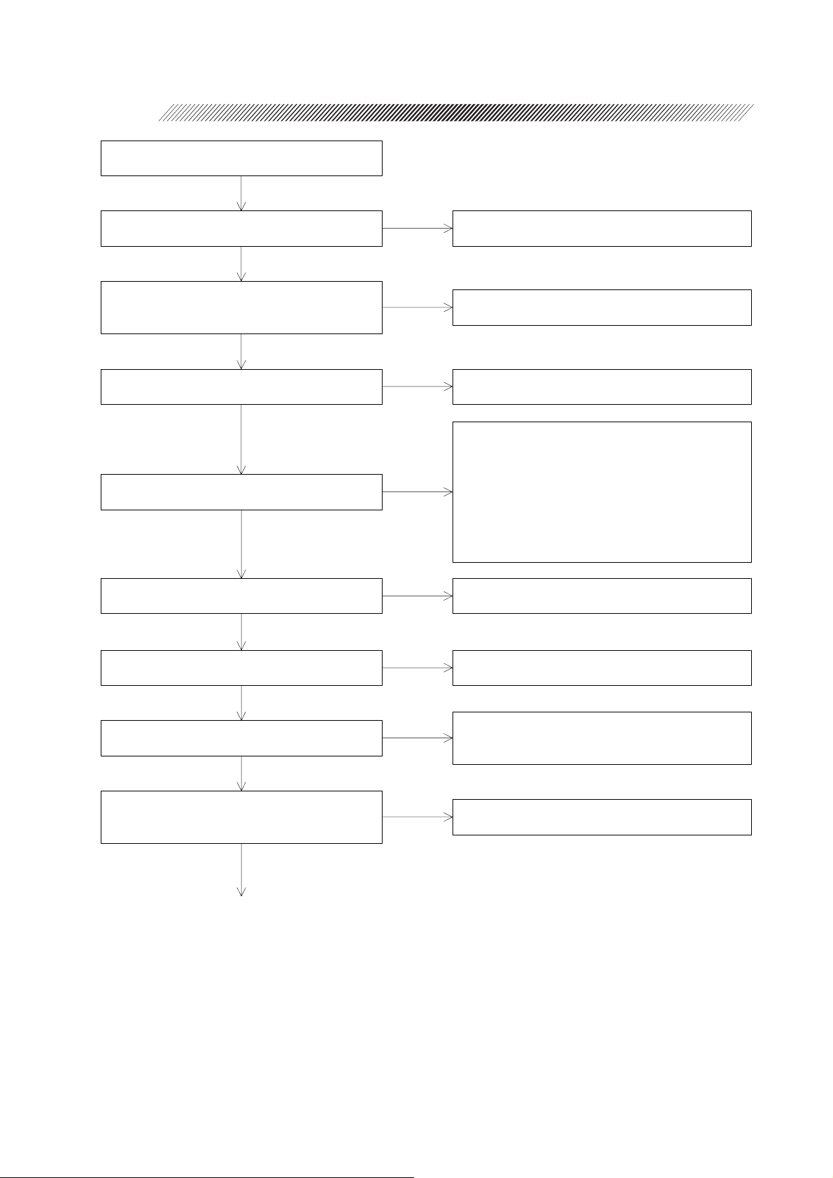
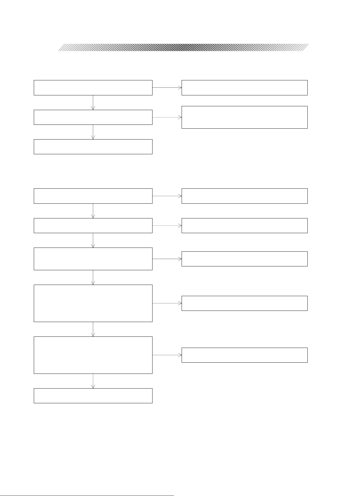
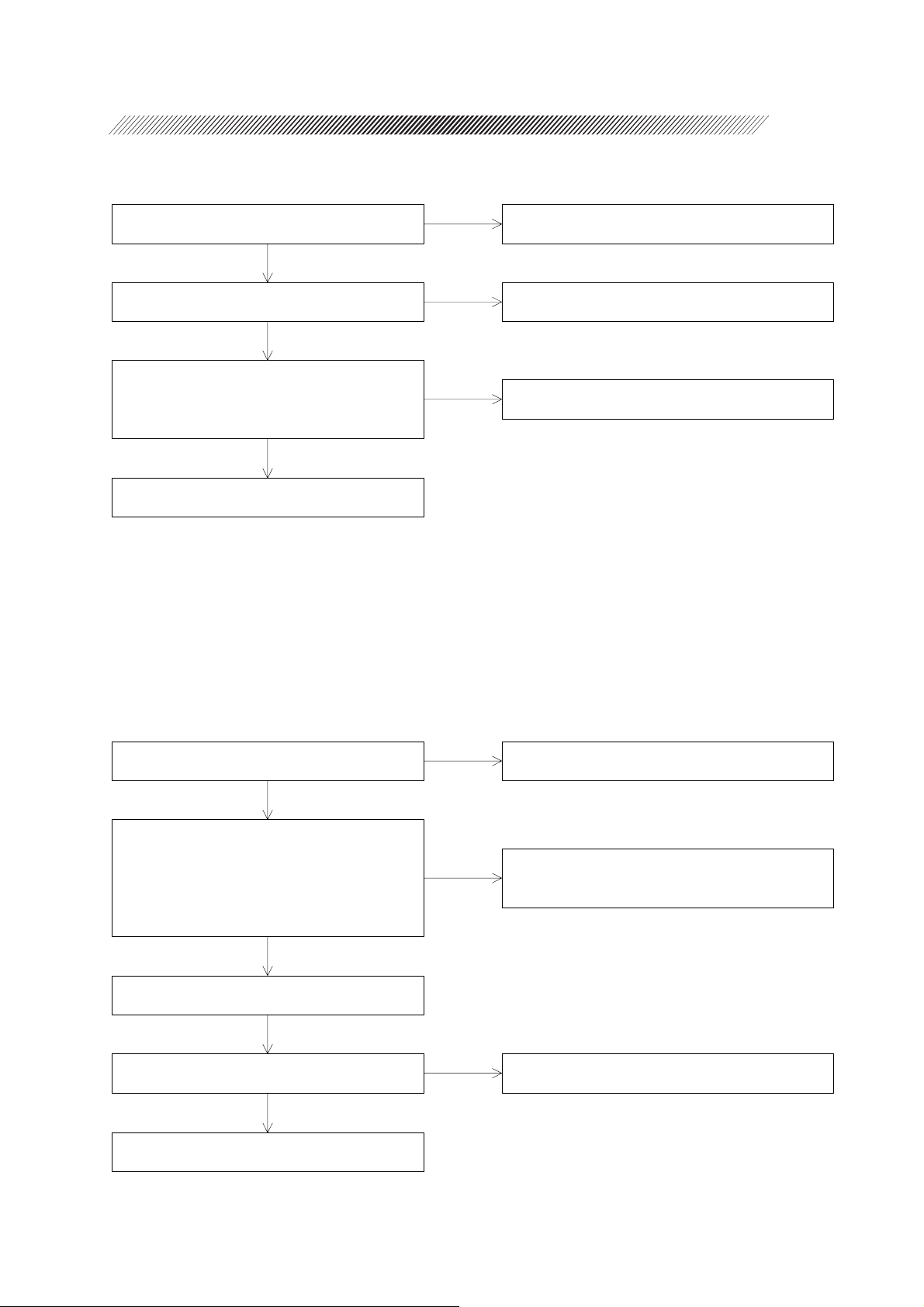
Turn ON the master switch.
Does the LINE indicator light up?
Yes
Does the LASER EMISSION indicator light
up by turning ON the key switch and does the
system start a countdown for 10 seconds?
Yes
Does the fan work?
Yes
After the countdown, do the POWER and
TIME displays indicate the setting values?
Yes
Can the coagulation power output be set
properly?
Yes
No
No
No
No
No
4.1 The LINE indicator lights up.
4.3 INTERLOCK 6.3 appears.
4.2 The fan does not work.
4.4 Error 1 appears.
4.5 Error 3 appears.
4.6 Error 13 appears.
4.7 Error 20 appears.
4.8 Error 21 appears.
4.9 Error 54 appears.
4.10 Any error in the 90s appears.
4.11 INTERLOCK 4.7 appears.
4.12 The coagulation power cannot be changed.
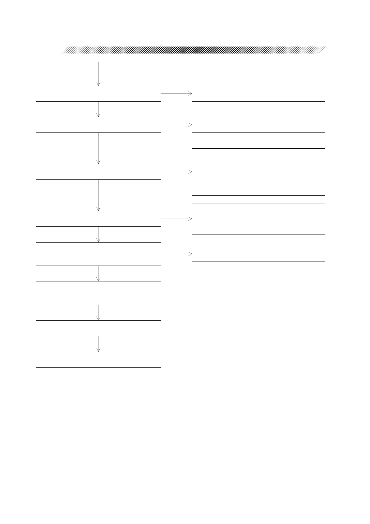
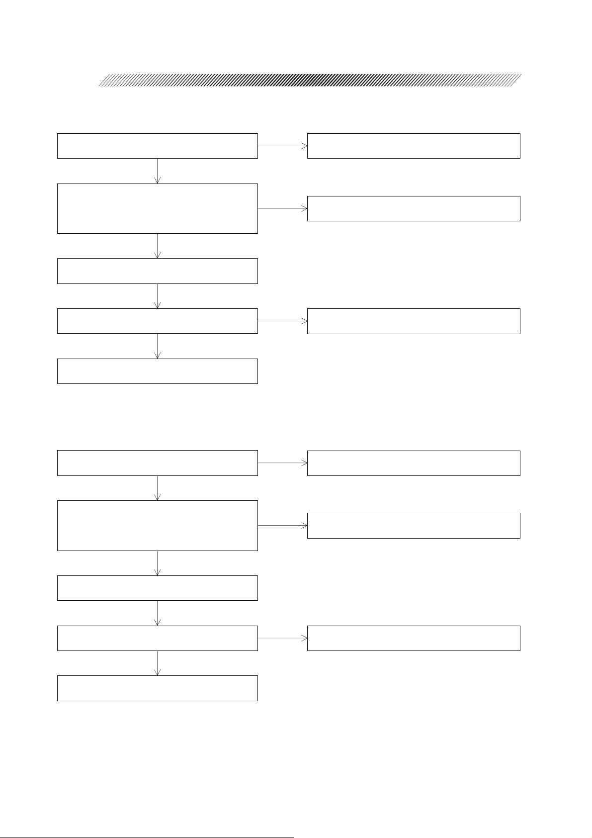
Can the coagulation time be set properly?
Yes
Can the brightness of the aiming beam
changed by pressing the AIMING switch?
Yes
Does the indication on the INTERVAL
display light up by pressing the INTERVAL
switch?
Yes
No
No
No
4.13 The coagulation time cannot be changed.
4.14 The brightness of the aiming beam cannot
be changed.
4.15 The aiming beam is invisible.
4.16 The interval time cannot be set.
3 - 2
This page is intentionally vacant.
Does the READY indicator light up by
pressing the STATUS switch?
Yes
Is the indication on the COUNTER display
reset to “0” by pressing the RESET switch?
Yes
Is the laser emitted by depressing the foot
switch?
Yes
Is the measured power output within the
specifications for the set values?
Yes
Do the laser emission stop, the indications of
the control box light off, and the fan stop by
pressing the emergency stop switch?
Yes
No
No
No
No
No
4.17 The READY indicator does not light up.
4.18 Counter cannot be reset.
4.19 Error 2 appears.
4.20 Error 53 appears.
4.21 Error 55 appears.
4.22 INTERLOCK 2.7 appears.
4.23 Error 10 appears.
4.24 Error 15 appears.
4.25 The power output is out of the specified
range.
4.26 When the spot size is set to 50μm, the
power output is out of the specified range.
4.27 The emergency stop switch cannot be
activated.
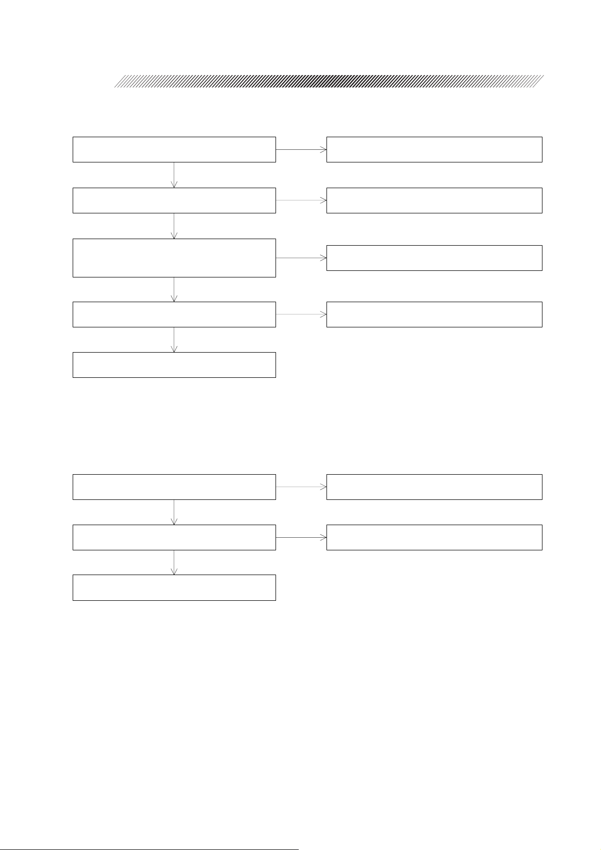
Turn ON the key switch. After the
countdown for 10 seconds, turn OFF the key
switch.
Turn OFF the master switch.
Completion of operation
§
4
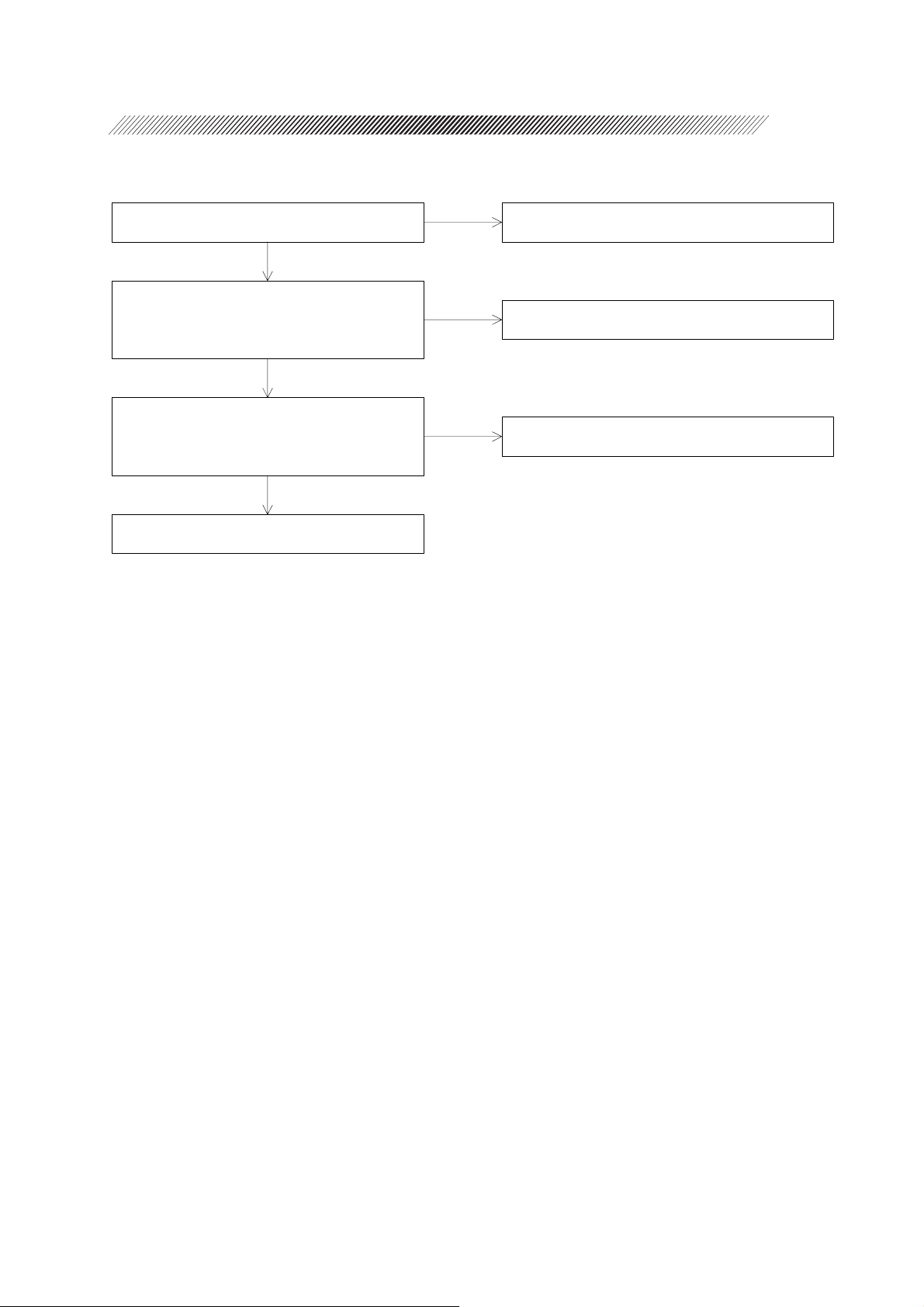
4.1 The LINE indicator does not light up.
SUB-TROUBLESHOOTING
Is the fuse in the fuse carrier blown?
No
Is the voltage between the 1st and 3rd pins of
P125 on the MASTER BOARD + 12 VDC?
Yes
Is the voltage between the 24th and 20th pins
of J108 on the MASTER BOARD
approximately + 4.0 VDC?
Yes
Does the cable between the 20th and 24th
pins of the CB CABLE ASSY have a break?
No
Replace the DISPLAY BOARD.
(See “6.15”.)
Yes
No
No
Yes
4.2 The fan does not work.
Replace the fuse with a new one.
(Refer to the Operator’s Manual.)
Replace the switching power supply.
(See “6.1”.)
Replace the MASTER board. (See “6.15”.)
Repair the faulty point.
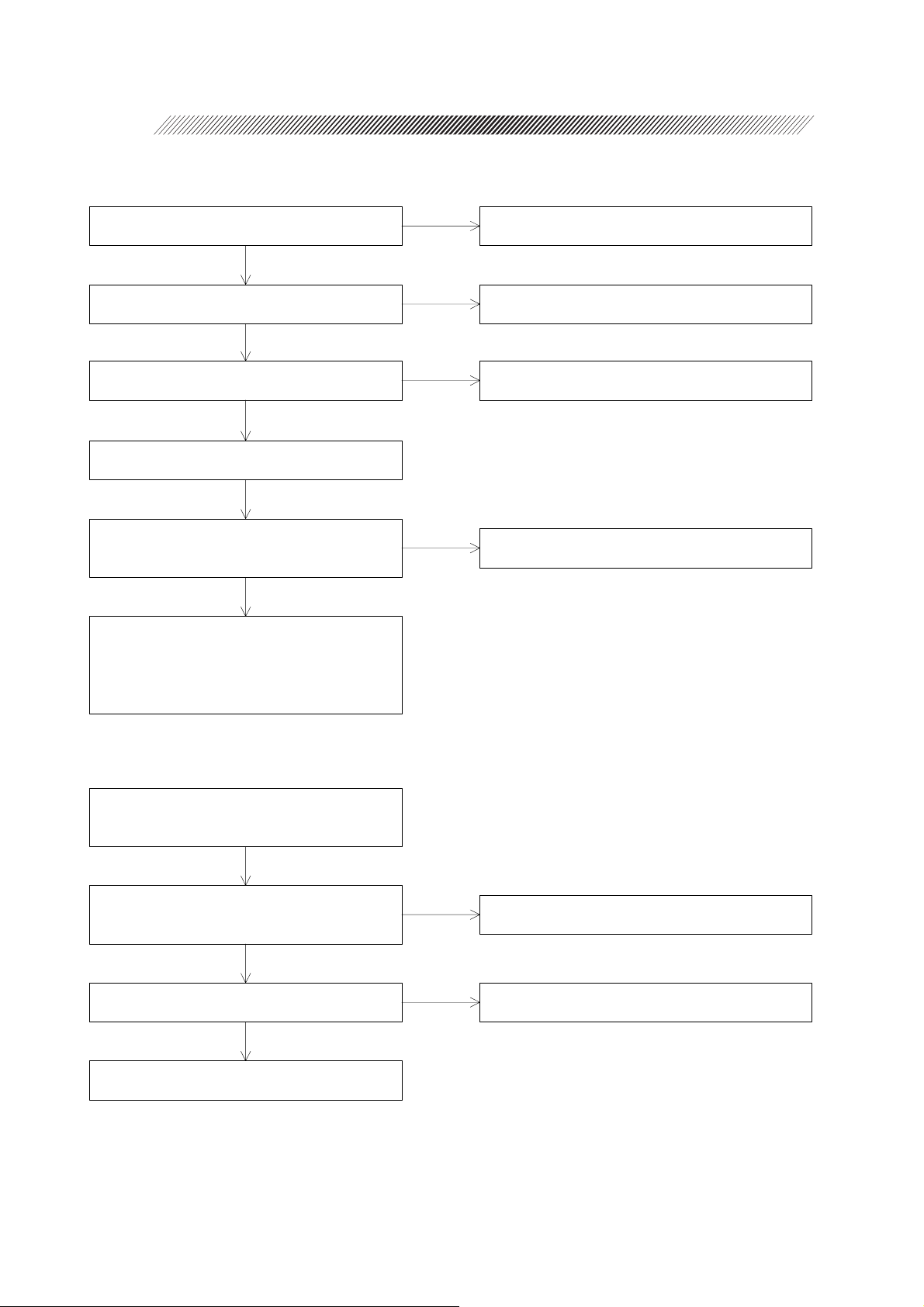
* The fan does not work when the temperature is lower than the specified one (25 degrees C).
Does the LINE indicator of the control box
light up?
Yes
Is the voltage between the 1st and 2nd pins of
J112 on the MASTER BOARD + 12 VDC?
Yes
Replace the FAN ASSY. (See “6.2”.)
No
No
Check the articles described in “4.1 The LINE
indicator does not light up.” (See “4.1”.)
Replace the MASTER BOARD. (See “6.15”.)
4 - 2
4.3 INTERLOCK 6.3 appears.
Is the REMOTE connector connected?
Yes
Is electricity applied between the 3rd and 4th
pins of the REMOTE connector?
Yes
Replace the MASTER BOARD.
(See “6.15”.)
4.4 Error 1 appears.
Does the COAG SHUTTER ASSY (EA04)
have a break?
No
Is the COAG SHUTTER ASSY positioned at
the detectable area of the sensor?
Yes
Is the voltage between the 3rd and 7th, 4th
and 7th pins of P106 (J106) on the MASTER
BOARD approximately + 1.3 DVC?
Yes
No
No
Yes
No
No
Connect the REMOTE connector.
Repair the faulty point between the 3rd and 4th
pins of the REMOTE connector, or replace the
REMOTE connector.
Repair or replace the COAG SHUTTER ASSY
(EA04). (See “6.4”.)
Perform the position adjustment of the COAG
SHUTTER ASSY.
Replace the COAG SHUTTER ASSY (EA04).
(See “6.4”.)
Is the voltage of P106 (J106) on the
MASTER BOARD as follows when the
COAG shutter is closed?
TP17: 5 V
TP18: 0 V
Yes
Is the voltage of P106 (J106) on the
MASTER BOARD as follows when the
COAG shutter is open?
TP17: 0 V
TP18: 5 V
Yes
Replace the MASTER BOARD.
No
No
Repair or replace the COAG SHUTTER ASSY
(EA04). (See “6.4”.)
Repair or replace the COAG SHUTTER ASSY
(EA04). (See “6.4”.)

4.5 Error 3 appears.
4 - 3
Does the AIMING SHUTTER ASSY (EA03)
have a break?
No
Is the AIMING SHUTTER ASSY positioned
at the detectable area of the sensor?
Yes
Is the voltage between the 3rd and 5th, 6th
and 5th pins of P107 (J107) on the MASTER
BOARD approximately + 1.3 DVC?
Yes
Is the voltage of P107 (J107) on the
MASTER BOARD as follows when the
aiming beam is OFF?
4th - 5th pins: 5 V
7th - 5th pins: 0 V
Yes
Is the voltage of P107 (J107) on the
MASTER BOARD as follows when the
aiming beam is ON?
4th - 5th pins: 0 V
7th - 5th pins: 5 V
Yes
No
No
No
No
Repair or replace the AIMING SHUTTER
ASSY (EA03). (See 6.6.)
Perform the position adjustment of the AIMING
SHUTTER ASSY.
Replace the AIMING SHUTTER ASSY (EA03).
(See 6.4.)
Repair or replace the AIMING SHUTTER
ASSY (EA03). (See 6.6.)
Repair or replace the AIMING SHUTTER
ASSY (EA03). (See 6.6.)
Yes
Replace the MASTER BOARD.
4.6 Error 13 appears.
Disconnect P113 (J113) on the MASTER
BOARD. Is the circuit between the 1st and
3rd pins of P113 on the TRANSISTOR
ASSY short-circuited?
No
Disconnect P114 (J114) on the MASTER
BOARD. Is the circuit between the 1st and
3rd pins of P114 on the TRANSISTOR
ASSY short-circuited?
No
Replace the MASTER BOARD. (See 6.15.)
Yes
Yes
Replace the TRANSISTOR ASSY. (See 6.7.)
Replace the TRANSISTOR ASSY. (See 6.7.)
4 - 4
4.7 Error 20 appears.
Does the LH CABLE ASSY have a break?
No
Disconnect P123 (J123) on the MASTER
BOARD. Is the resistance between the 1st
and 2nd pins of P123 of the LH CABLE
ASSY 6 - 12 KΩ?
Yes
Replace the MASTER BOARD. (See 6.15.)
Is the symptom improved?
Yes
Completion of operation
4.8 Error 21 appears.
Yes
No
No
Repair or replace the LH CABLE ASSY.
Replace the laser head. (See 6.16.)
Replace the laser head. (See 6.16.)
Does the LH CABLE ASSY have a break?
No
Disconnect P123 (J123) on the MASTER
BOARD. Is the resistance between the 3rd
and 2nd pins of P123 of the LH CABLE
ASSY 8 - 12.5 KΩ?
Yes
Replace the MASTER BOARD. (See 6.15.)
Is the symptom improved?
Yes
Completion of operation
Yes
No
No
Repair or replace the LH CABLE ASSY.
Replace the laser head. (See 6.16.)
Replace the laser head. (See 6.16.)
4.9 Error 54 appears.
4 - 5
Can the FIBER SW be turned ON when the
fiber optic cable plug is connected?
Yes
Is electricity applied between the 2nd and 3rd,
5th and 6th pins of P105 when the micro
switch of the FIBER SW ASSY (EA01) is
turned ON?
Yes
Disconnect P105 (J105) on the MASTER
BOARD. Is the voltage of J105 as follows?
2nd - 3rd pins: 5 V
5th - 6th pins: 5 V
Yes
Completion of operation
No
No
No
Perform the position adjustment of the FIBER
SW.
Replace the MASTER BOARD. (See 6.15.)
4.10 Any error in the 90s appears.
Replace the FIBER SW ASSY (EA01).
(See 6.8.)
Replace the MAIN CPU (17164-E150) and SUB CPU (17164-E160). (See 6.9.)
4 - 6
4.11 INTERLOCK 4.7 appears.
Does the fan work?
Yes
Does any object block the air vent of the
instrument?
Yes
Is the temperature of the room within the
specified range (10 - 30℃) for usage?
Yes
Leave the instrument for 30 minutes or longer
for natural cooling.
Can the instrument be used without
INTERLOCK 4.7 when restarting the
instrument?
Yes
The instrument is normal.
Although INT4.7 appeared because the
temperature of the instrument temporarily
rose. The temperature of the instrument has
lowered now and the instrument can be used.
No
No
No
No
Check the articles described in “4.2 The fan does
not work.” (See “4.2”.)
Move the object which blocks the air vent, or
move the instrument.
Make the temperature of the room the same as
the specified.
Replace the MASTER BOARD. (See 6.15.)
4.12 The coagulation power cannot be changed.
Turn OFF the key switch. After the
indications of the control box go off, turn ON
the key switch again.
Is the voltage between the 16th and 18th, 17th
and 19th pins of P108 (J108) of the
MASTER BOARD 5 V?
Yes
Does the CB CABLE ASSY (EA13) have a
faulty soldering or break?
No
Replace the MASTER BOARD. (See 6.15.)
No
Yes
Replace the MASTER BOARD. (See 6.15.)
Repair or replace the CB CABLE ASSY.
(See 6.10.)

4 - 7
4.13 The coagulation time cannot be changed.
Check and perform the articles described in 4.12.
4.14 The brightness of the aiming beam cannot be changed.
Check and perform the articles described in 4.12.
4.15 The aiming beam is invisible.
Does the aiming shutter block the optical
path?
No
Is the voltage between the TP12 and GND on
the MASTER BOARD 1.2 V, and is the
aiming beam emitted from the AIMING LD
ASSY (EA02)?
Yes
Can the aiming beam be seen by turning VR1
on the MASTER BOARD clockwise?
Yes
Adjust the power output of the aiming beam.
(See 7.6.2.)
Yes
No
No
Adjust the operation of the AIMING SHUTTER
ASSY.
Replace the AIMING LD ASSY. (See 6.11.)
Replace the MASTER BOARD. (See 6.15.)
4.16 The interval time cannot be changed.
Check and perform the articles described in 4.12.
4.17 The READY indicator does not light up.
Check and perform the articles described in 4.12.
4.18 The counter cannot be reset.
Check and perform the articles described in 4.12.

4 - 8
4.19 Error 2 appears.
Is the connector of the delivery unit
connected to P702 (J702) on the DELIVERY
BOARD (17621-E4965)?
Yes
Does the delivery setting of the main body
coincide with the connected delivery unit?
Yes
Does the DELIVERY BOARD ASSY
(EA08) have a break?
No
Is the voltage of P104 (J104) on the
MASTER BOARD as follows?
11th - 12th pins: About + 15 V
Yes
Is the voltage of TP on the MASTER
BOARD as follows?
TP14: 0 V
TP15: 5 V
Yes
No
No
Yes
No
No
Connect the connector of the delivery unit to
P702 (J702) on the DELIVERY BOARD.
Select the proper delivery setting of the main
body.
Repair or replace the DELIVERY BOARD
ASSY (EA08). (See 6.12.)
Replace the MASTER BOARD. (See 6.15.)
The delivery unit malfunctions. (Refer to the
Service Manual of the delivery unit.)
Is the voltage of TP on the MASTER
BOARD as follows when the filter is open?
TP14: 5 V
TP15: 0 V
Yes
Replace the MASTER BOARD. (See 6.15.)
No
The delivery unit malfunctions. (Refer to the
Service Manual of the delivery unit.)
4.20 Error 53 appears.
4 - 9
Does the FOOT SW ASSY (EA11) have a
break?
No
Does Err.53 occur when depressing the foot
switch slowly?
No
Is electricity applied between the 1st and 4th,
3rd and 4th pins of P101 (J101) on the
MASTER BOARD when the foot switch is
depressed?
Yes
Replace the MASTER BOARD. (See 6.15.)
Yes
Yes
No
4.21 Error 55 appears.
Check and perform the articles described in 4.19.
Repair or replace the FOOT SW ASSY (EA11).
Adjust the switch in the foot switch.
Replace the foot switch (10149-0000).
4.22 INTERLOCK 2.7 appears.
Does the 1st MONITOR of the POWER
MONITOR ASSY (EA05) have a break?
No
Measure the actual power output at the
aperture of the delivery unit. Is the measured
power output within the specified range?
[Specified power]
90 mW or less: ±20%
100 mW or more: ±15%
No
Perform the adjustment for the overpower.
(See 7.6.3.)
Is the symptom improved? Completion of operation
No
Replace the MASTER BOARD. (See 6.15.)
Yes
Yes
Yes
Repair or replace the POWER MONITOR
ASSY (EA05).
Adjust the power output at the aperture of the
delivery unit until it becomes within the
specified range. (See 7.6.1.)
 Loading...