


NIDEK
AUTO REF/KERATOMETER
Model ARK710A
SERVICE MANUAL
January 9, 2004
Pages in total: 82
MRK4D*RDA001A/E

Table of Contents
§1 §2
INTRODUCTION |
Page |
1-1 |
|
SAFETY.......................................................................................................................... |
2-1 |
2.1 General Precautions.................................................................................................... |
2-1 |
2.2 Maintenance Precautions ............................................................................................ |
2-1 |
2.3Adjustment Precautions .............................................................................................. |
2-2 |
§3 §4
TROUBLESHOOTING ................................................................................................ |
3-1 |
SUB-TROUBLESHOOTING ....................................................................................... |
4-1 |
4.1 The TV monitor displays nothing. / The TV monitor display is abnormal. ...................... |
4-1 |
4.2 The “ERR” message appears after turning ON the power switch.................................. |
4-2 |
4.2.1 “ERR 1” (sensor carry error) appears. ............................................................... |
4-2 |
4.2.2 “ERR 2” (target carry error) appears. ................................................................ |
4-3 |
4.2.3 “ERR 3” (rotator error) appears. ....................................................................... |
4-4 |
4.2.4 “ERR 7” (printer error) appears......................................................................... |
4-5 |
4.2.5 “ERR 9” (MEMORY FAILURE ON EEPROM) appears. ................................ |
4-6 |
4.2.6 “ERR A” (MEMORY FAILURE ON RAM) appears. ....................................... |
4-6 |
4.2.7 “PD ERR” appears. .......................................................................................... |
4-7 |
4.3 The TV monitor does not brighten up. ......................................................................... |
4-8 |
4.4 The eye image does not appear on the TV monitor. ..................................................... |
4-9 |
4.5 The characters and target are not clear or they are not indicated on the TV monitor. ..... |
4-9 |
4.6 Switching between the manual mode and auto-tracking mode cannot be done. ........... |
4-10 |
4.7 The parameter cannot be changed............................................................................. |
4-10 |
4.8 The horizontal movement of the main body is not smooth. .......................................... |
4-11 |
4.9 The vertical movement of the measuring unit is not smooth. ........................................ |
4-12 |
4.10 The measuring unit is unstable. ................................................................................ |
4-12 |
4.11 The mire ring does not appear. ................................................................................ |
4-13 |
4.12 The model eye image is not clear. ............................................................................ |
4-14 |
4.13 AR measurement does not start. (The Start button is not operable.) ........................ |
4-14 |
4.14 The “ERR” message appears duringAR measurement. ............................................ |
4-15 |
4.15 Only the obtained SPH value is shifted. ................................................................... |
4-16 |
4.16 The obtained CYL value is too high......................................................................... |
4-17 |
4.17 Ashort beep cannot be heard when starting the measurement. ................................. |
4-18 |
4.18 The IOL mode cannot be selected. ......................................................................... |
4-18 |
4.19 The CYL mode cannot be selected. ........................................................................ |
4-18 |
4.20 Switching between L and R cannot be done. ........................................................... |
4-19 |
4.21 The PD mode cannot be established. ...................................................................... |
4-19 |
4.22 The value obtained by the PD measurement is abnormal. ......................................... |
4-20 |
4.23 The up-and-down movement of the chin rest is not smooth. ..................................... |
4-20 |
4.24 The chart cannot be seen. ....................................................................................... |
4-20 |

4.25 The blink error is not detected. ............................................................................... |
4-21 |
4.26 The auto-tracking cannot be performed................................................................... |
4-22 |
4.27 The auto-shot cannot be performed. ....................................................................... |
4-23 |
4.28 “ERR IF” appears. ................................................................................................. |
4-24 |
4.29 The printing cannot be done. ................................................................................... |
4-25 |
4.30 The print is too light. / The printout has missing characters....................................... |
4-26 |
4.31 The eyeprint mode cannot be selected..................................................................... |
4-26 |
4.32 The auto-off mode cannot be activated. .................................................................. |
4-27 |
4.33 Switching of the R/K measurement mode cannot be done. ....................................... |
4-27 |
4.34 “ERR” appears during the KM measurement........................................................... |
4-28 |
4.35 The data obtained by the KM measurement is abnormal. ......................................... |
4-28 |
§5 REMOVING COVERS................................................................................................. |
5-1 |
5.1 Removing the front, left and right covers ...................................................................... |
5-1 |
5.2 Removing the rear cover of the measuring unit ............................................................. |
5-1 |
5.3 Removing the inner cover............................................................................................ |
5-1 |
5.4 Removing the rear cover ............................................................................................. |
5-1 |
5.5 Removing the TV panel .............................................................................................. |
5-1 |
5.6 Replacing the bottom plate.......................................................................................... |
5-1 |
§6 REPLACING THE BOARDS....................................................................................... |
6-1 |
6.1 Replacing the BA01 and BA22 boards ....................................................................... |
6-1 |
6.2 Replacing the BA32 board ......................................................................................... |
6-1 |
6.3 Replacing the BA06 board ......................................................................................... |
6-1 |
6.4 Replacing the BA07 board ......................................................................................... |
6-1 |
6.5 Replacing the BA28 board ......................................................................................... |
6-1 |
6.6 Replacing the BA23 board ......................................................................................... |
6-1 |
§7 REPLACING THE PARTS ........................................................................................... |
7-1 |
7.1 Replacing the transformer ........................................................................................... |
7-1 |
7.2 Replacing the joystick ................................................................................................. |
7-1 |
7.3 Replacing and cleaning the slide plate .......................................................................... |
7-1 |
7.4 Replacing the PD LED unit and cleaning the IR filter .................................................... |
7-1 |
7.5 Replacing the INC/DEC SW unit................................................................................ |
7-1 |
7.6 Replacing the mire ...................................................................................................... |
7-2 |
7.7 Replacing the KM LED unit........................................................................................ |
7-2 |
7.8 Replacing the target origin unit..................................................................................... |
7-3 |
7.9 Replacing the CCD camera ........................................................................................ |
7-3 |
7.10 Replacing the wheel guideASSY .............................................................................. |
7-3 |
7.11 Replacing the pinion .................................................................................................. |
7-4 |
7.12 Replacing the shaft.................................................................................................... |
7-4 |
7.13 Replacing the bearing................................................................................................ |
7-4 |
7.14 Replacing the U/D MOTOR unit............................................................................... |
7-4 |
7.15 Replacing the U/D LIMIT unit .................................................................................. |
7-4 |
7.16 Replacingthe measuring unit ..................................................................................... |
7-5 |
7.17 Replacing the TV monitor ......................................................................................... |
7-5 |
7.18 Replacing the LED ................................................................................................... |
7-6 |
7.19 Replacing the chart LED lamp unit ............................................................................ |
7-6 |

7.20 Replacing the printer unit........................................................................................... |
7-6 |
7.21 Replacing the ILLUMI LED unit ............................................................................... |
7-6 |
§8 ADJUSTMENT ............................................................................................................. |
8-1 |
8.1 Optical axis adjustment of phototransmitter/photoreceptor ........................................... |
8-1 |
8.1.1 Optical axis check of phototransmitter/photoreceptor ......................................... |
8-1 |
8.1.2 Optical axis adjustment of phototransmitter/photoreceptor .................................. |
8-1 |
8.2 Optical axis adjustment of chart .................................................................................. |
8-3 |
8.2.1 Optical axis check of chart ................................................................................ |
8-3 |
8.2.2Adjustment of chart in vertical direction .............................................................. |
8-4 |
8.2.3Adjustment of chart in horizontal direction .......................................................... |
8-4 |
8.3 Three-point relationship among SPD, mask and LED .................................................. |
8-4 |
8.3.1 Check of the three-point relationship among SPD, mask and LED ...................... |
8-4 |
8.3.2 Perpendicular adjustment of the SPD and mask photoreceptor ........................... |
8-4 |
8.3.3 Tilt adjustment of LED lights and mask photoreceptor ........................................ |
8-5 |
8.3.4 LED adjustment in the middle ............................................................................ |
8-6 |
8.3.5 Check after adjustment of three-point relationship among SPD, mask and LED .. |
8-6 |
8.4 Position adjustment of target and LED lights ................................................................ |
8-7 |
8.5 CYL value adjustment ................................................................................................ |
8-7 |
8.5.1 When the height of the side-by-side waveforms is different ................................. |
8-7 |
8.5.2Opticalaxisadjustmentofphototransmitter/photoreceptorsysteminhorizontaldirection |
|
.................................................................................................................................. |
8-8 |
8.5.3 Optical axis adjustment of phototransmitter/photoreceptor system in vertical direction |
|
.................................................................................................................................. |
8-8 |
8.5.4 Check after waveform adjustment ...................................................................... |
8-8 |
8.6 Measurable range adjustment...................................................................................... |
8-8 |
8.7 SPH value calibration ................................................................................................. |
8-8 |
8.8ARAXIS adjustment .................................................................................................. |
8-8 |
8.9 IOL check.................................................................................................................. |
8-8 |
8.10 Chart calibration ....................................................................................................... |
8-9 |
8.11 Internal reflection check .......................................................................................... |
8-10 |
8.12 Tilt adjustment of Chart........................................................................................... |
8-10 |
8.13 PD adjustment........................................................................................................ |
8-10 |
8.13.1 PD adjustment .............................................................................................. |
8-10 |
8.13.2 PD (64 mm and 80 mm) offset adjustment ..................................................... |
8-11 |
8.14Auto-shot adjustment.............................................................................................. |
8-11 |
8.15Adjusting the up-and-down movement of the measuring unit .................................... |
8-11 |
8.15.1Adjusting the tightness of the nut stopper ........................................................ |
8-11 |
8.15.2Adjusting the tightness of the screws retaining the up-down bearings ............... |
8-11 |
8.15.3Adjusting the lead screw for up-and-down movement .................................... |
8-11 |
8.16 Cleaning the measuring window .............................................................................. |
8-11 |
8.17 Cleaning the model eyes and steel balls ................................................................... |
8-11 |
8.18 Tracking and auto-shot calibration........................................................................... |
8-12 |
8.19 Setting the mask blink level ..................................................................................... |
8-12 |
8.20 Setting print density ................................................................................................ |
8-12 |
8.21 Setting sensor offset................................................................................................ |
8-13 |
8.22 Sensor calibration ................................................................................................... |
8-13 |
8.23 Setting EEPROM DATA ........................................................................................ |
8-13 |

8.24Adjusting the up-and-down movement of the chin rest ............................................. |
8-13 |
8.25 KM calibration ....................................................................................................... |
8-13 |
§9 REFERENCE ................................................................................................................ |
9-1 |
9.1WiringDiagram .......................................................................................................... |
9-1 |
9.2 Connecting Cables ..................................................................................................... |
9-2 |
9.3Configuration............................................................................................................ |
9-11 |
9.4 Labels ...................................................................................................................... |
9-13 |
9.5 Error code table ....................................................................................................... |
9-14 |
9.6 List of jigs, tools and consumables ............................................................................ |
9-15 |

§1 INTRODUCTION
This service manual contains service instructions for the NIDEK AUTO REF/KERATOMETER, ARK-710A.
For correct service, thorough understanding of the contents of this manual is required prior to the service. In this manual, simple replacement work of various units is described as countermeasures against troubles.
The disassembling and repair work must be performed by NIDEK service personnel, or technicians trained for the service work of the ARK-710A by NIDEK.
Use this manual together with the ARK-710A Operator’s Manual.
The specifications and design of this instrument are subject to change without notice for improvement. In the case of major changes, refer to the corresponding TECHNICAL BULLETIN issued in each occasion.
If the instrument cannot be repaired by repair operations in accordance with this Service Manual, please inform NIDEK of the Serial Number of the instrument, and details of the symptom. If the measurement is possible, please inform NIDEK of the data of the model eyes (-10D, 0D, +10D) and steel balls (5.95 mm, 7.94 mm, 9.13 mm).

§2 SAFETY
2.1 General Precautions
•Only service persons who are accustomed to using the required tools and have a deep knowledge of this instrument are allowed to repair the instrument.
•Observe the procedures to perform the repair work. If not, accidents or failure of the instrument may result.
•When performing the maintenance work, turn OFF the power switch, and disconnect the power cord from the wall outlet unless the power needs to be ON.
•Never wipe the covers etc. using an organic solvent such as a paint thinner. The surface may be damaged, and the appearance of the instrument will be impaired as a result.
•For procedures similar to the ones of the AR-630A, “see “*.*” of the AR-630A Service Manual.” will be described in this manual. Use the AR-630A Service Manual together with this manual.
2.2 Maintenance Precautions
•In case of instrument malfunction, turn OFF the power switch after checking the symptom.
•Never drop parts or screws inside the instrument, nor bump it against surrounding objects.
•Prepare storage cases so as not to lose the removed screws or parts.
•Screw or unscrew the screws with proper tools.
•After loosening the screws fixed by a thread-locking adhesive, be sure to reapply the threadlocking adhesive to the screws when you retighten them.
•After replacing parts, make sure that they are fixed securely before turning ON the power.
•If you observe strange odors or smoke being issued from the instrument, immediately turn OFF the instrument, disconnect the power cord from the outlet, and isolate the cause. If the instrument is powered in abnormal conditions, fire, electric shock or total loss of the instrument may result.

2 - 2
•Refer to “9.1 Wiring diagram” and “9.2 Connectors and cables,” for checking cable breaks as described in “§3 TROUBLESHOOTING”. In addition, check cables for the following:
 Connectors are connected and crimped securely.
 No contact failure occurs after re-connection of connectors.
 Cables are soldered properly.
•Do not pull the cables strongly. Cable breaks etc. may result.
•Never perform maintenance work with wet hands. Electric shock or failure of the instrument may result.
2.3 Adjustment Precautions
•Perform adjustment on a vibration-free, stable and level surface.
A slanted floor or place subject to vibration will obstruct accurate adjustment.
•Never use adjustment jigs for purposes not instructed in this manual.
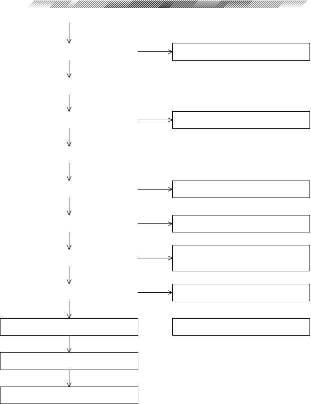
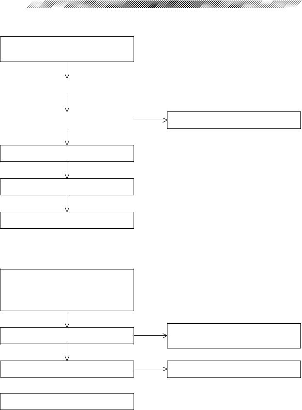
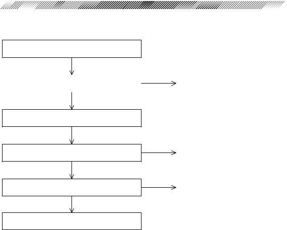
§3 TROUBLESHOOTING
Connect the power cord to a wall outlet and turn ON the power switch.
|
|
|
Does the initialization complete and do the |
|
|
SPH, CYL and Axis values indicate “0”? |
|
|
|
|
|
|
|
|
Does the TV monitor brighten up? |
||
|
|
|
|
|
|
|
|
|
Does the eye image appear on the TV |
|
|
monitor? |
|
|
|
|
|
|
|
|
Do the characters appear on the TV monitor |
|
|
clearly? |
|
|
|
|
|
|
|
|
Press the 3D Auto button. |
|
|
|
|
|
|
||
Can the manual mode be selected? |
||
|
||
|
|
|
|
|
|
|
|
|
Can the increments of parameter 1 be |
|
|
changed to 0.01? |
|
|
|
|
Can the “R” measurement mode be selected? Yes
4.1The TV monitor displays nothing. / The TV monitor display is abnormal.
4.2The “ERR” message appears after turning ON the power switch.
4.3The TV monitor does not brighten up.
4.4The eye image does not appear on the TV monitor.
4.5The characters or target are not clear or they are not indicated on the TV monitor.
4.6Switching between the manual mode and auto tracking mode cannot be done.
4.7The parameter cannot be changed.
4.33The switching of R/K measurement mode can not be done.
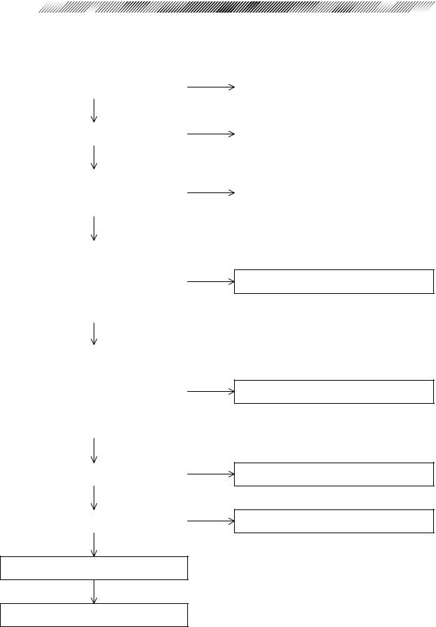
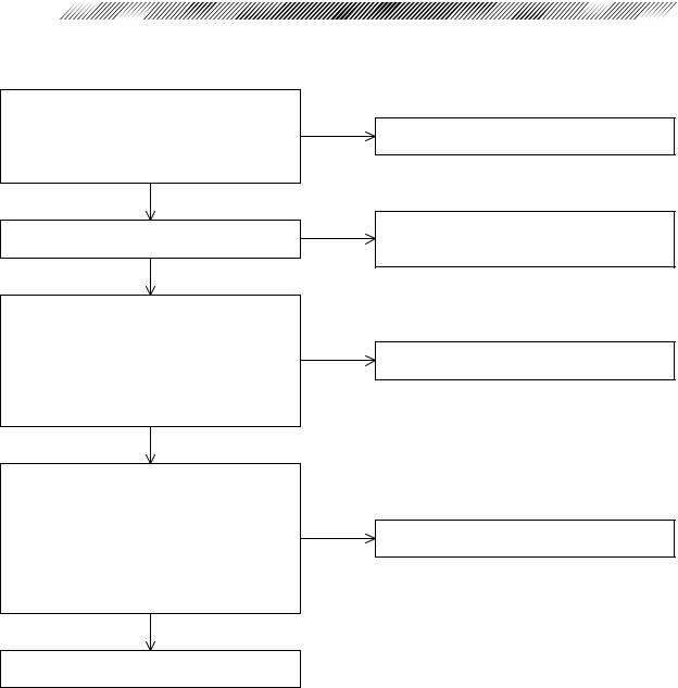
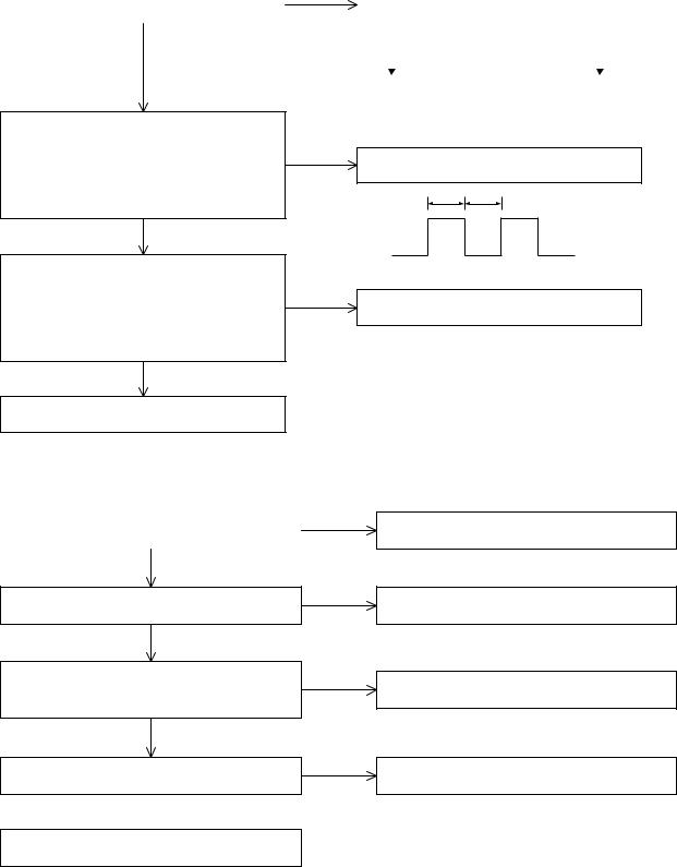
Attach the model eye to the chin rest.

3 - 2
|
|
Is the horizontal movement of the main body |
|
smooth? |
|
Yes |
|
|
|
Is the up-and-down movement of the |
|
measuring unit smooth? |
|
Yes |
|
|
|
Does the mire ring appear? |
|
|
|
|
|
|
|
Does the model eye image appear on the TV |
|
monitor clearly? |
|
|
|
|
|
Can the model eye be measured? |
|
|
|
|
|
|
|
Is the measured data of the model eye proper?
|
|
|
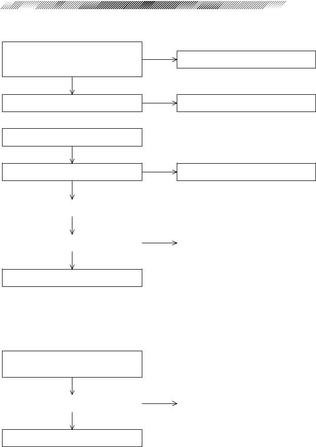
Can a short beep be heard when starting the |
|
|
measurement? |
|
|
Yes |
|
|
|
|
|
Can the IOL mode be selected by pressing the |
|
|
IOL button? |
|
|
|
|
|
|
|
|
Can the CYL mode be selected? |
||
|
||
|
|
|
|
|
|
|
|
|
Can switching between L and R be done? |
||
|
|
|
Yes |
|
4.8The horizontal movement of the main body is not smooth.
4.9The up-and-down movement of the measuring unit is not smooth.
4.10The measuring unit is unstable.
4.11The mire ring does not appear.
4.12The model eye image is not clear.
4.13AR measurement does not start.
4.14The “Err” message appears during AR measurement.
4.15Only the obtained SPH value is shifted.
4.16The obtained CYL value is too high.
4.17A short beep cannot be heard when starting the measurement.
4.18The IOL mode cannot be selected.
4.19The CYL mode cannot be selected.
4.20Switching between L and R cannot be done.
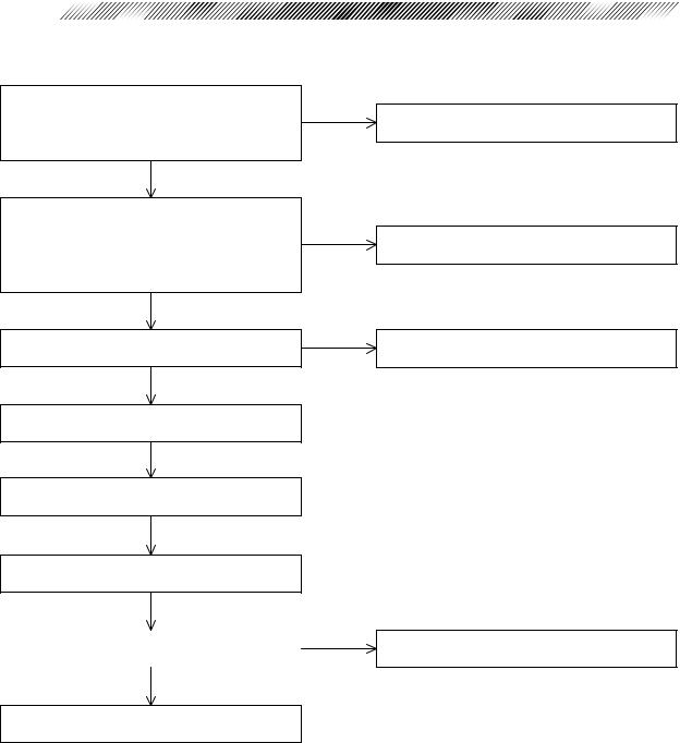
Change the increment of parameter 1 to “0.25”.

Press the Change button. |
|
Attach a scale to the model eye. |
|
Can the PD measurement be performed? |
|
|
|
Can the “K” measurement mode be selected?
Can the steel ball be measured? |
|
|
|
|
|
|
|
Is the obtained measurement data of the steel ball proper?
Yes
Press the Change button to select the “R/K” measurement mode.
Measure the human eye for check.
Is the up-and-down movement of the chin rest smooth?
Yes
Can the chart be seen through the measuring window? 
Yes
3 - 3
4.21The PD mode cannot be established.
4.22The value obtained by the PD measurement is abnormal.
4.33Switching of the R/K measurement mode cannot be done.
4.34The “Err” message appears during the KM measurement.
4.35The data obtained by the KM measurement is abnormal.
4.23The up-and-down movement of the chin rest is not smooth.
4.24 The chart cannot be seen.
3 - 4
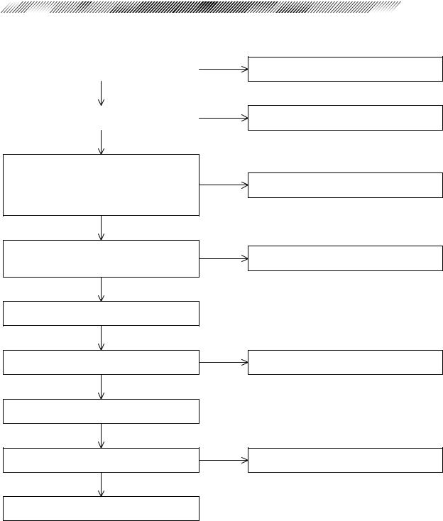
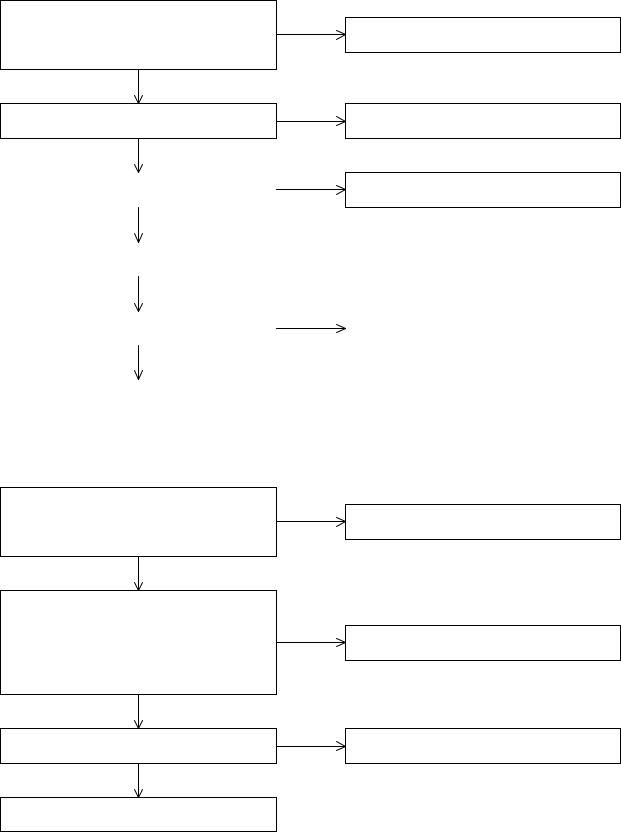
Can the blink error be detected? |
|
|
|
|
|
Yes |
|
|
|
Change from the manual mode to the auto- |
|
tracking mode. |
|
|
|
Can the auto-tracking be performed? |
|
|
|
|
|
|
|
|
|
Change to the auto-shot mode. |
|
|
|
|
|
Can the auto-shot be performed? |
|
|
|
|
|
Yes |
|
|
|
Can the communication be done? |
|
|
|
|
|
Yes |
|
|
|
Can the printing be done? |
|
|
|
|
|
Yes |
|
|
|
Can the eyeprint be done? |
|
|
|
|
|
Yes |
|
Can the auto-off mode of the TV monitor be activated? 
Yes
Turn OFF the power switch.
Completion of operation
4.25The blink error during measurement cannot be detected.
4.26The auto-tracking cannot be performed.
4.27The auto-shot cannot be performed.
4.28The “ERR IF” appears.
4.29Printing cannot be done.
4.30The print is too light. /The printout has missing characters.
4.31The eyeprint mode cannot be selected.
4.32The auto-off mode cannot be activated.
§4 SUB-TROUBLESHOOTING
4.1The TV monitor displays nothing. / The TV monitor display is abnormal.
|
|
|
Is the fuse proper? |
|
Replace the fuse. |
|
(Refer to the Operator’s Manual.) |
|
|
|
|
Yes |
|
|
|
|
|
Is the voltage supplied to the AC INLET |
|
It is recommended to install a voltage regulator. |
proper? |
|
|
|
|
|
|
|
|
|
|
|
Do the following connectors have poor |
|
|
electrical contact? |
Yes |
Re-connect the connector. |
BA01 board: P103 (J3) |
|
|
|
|
|
BA07 board: P701 (J1), P702 (J2) |
|
|
|
|
|
|
|
|
No |
|
|
Is the voltage supplied to P701 (J1) on the |
|
|
BA07 board proper? |
|
|
1st - 2nd pins: 14VAC |
|
|
3rd - 4th pins: 18VAC |
||
|
||
5th - 6th pins: 18VAC |
|
|
7th - 8th pins: 18VAC |
|
|
9th - 10th pins: 10VAC |
|
|
|
|
|
|
|
Is the voltage supplied to P702 (J2) on the |
|
BA07 board proper? |
|
1st - 2nd pins: +15VDC |
|
5th - 6th pins: +15VDC |
|
7th - 6th pins: -15VDC |
|
3rd - 4th pins: +5VDC |
|
10th - 4th pins: +5VDC |
|
8th - 9th pins: +12VDC |
|
|
|
Yes |
|
|
|
Does the power I/F cable (32906-EA59) have |
Yes |
a breakage? |
|
No |
|
|
|
Does the DISPLAY cable (32906-EA31) |
Yes |
have a breakage? |
|
No |
|
Replace the transformer. (See “7.1”.)
Replace the BA07 board. (See “6.4”.)
Repair the power I/F cable (32906-EA59) or replace it. (See “9.2”.)
Repair the DISPLAY cable (32906-EA31) or replace it. (See “9.2”.)
Replace the BA01 board. (See “6.1”.)
Replace the BA32 board. (See “6.2”.)

4 - 2
4.2The “ERR” message appears after turning ON the power switch.
4.2.1 “ERR 1” (sensor carry error) appears.
Do the following connectors have poor electrical contact?
BA01 board: P103 (J3), P106 (J6) Yes Reconnect the connectors. BA06 board: P601 (J1), P603 (J3), P604 (J4)
BA07 board: P701 (J1), P702 (J2)
No
Is the voltage supplied to P701 (J1) on the BA07 board proper?
1st - 2nd pins: 14VAC 3rd - 4th pins: 18VAC 5th - 6th pins: 18VAC 7th - 8th pins: 18VAC 9th - 10th pins: 10VAC

Is the voltage supplied to P702 (J2) on the BA07 board proper?
1st - 2nd pins: +15VDC 5th - 6th pins: +15VDC 7th - 6th pins: -15VDC 3rd - 4th pins: +5VDC 10th - 4th pins: +5VDC 8th - 9th pins: +12VDC
Yes
Does the rotator pulse motor unit (32906EA54) have a breakage?
No
Replace the BA06 board. (See “6.3”.)
Perform the sensor calibration. (See “8.22”.)
Replace the BA01 board. (See “6.1”.)
Is the symptom improved?
No
Yes
Yes
Replace the transformer. (See “7.1”.)
Replace the BA07 board. (See “6.4”.)
Repair the rotator pulse motor unit (32906EA54) or replace it. (See “9.2”.)
Completion of operation
Replace the measuring unit. (See “7.16”.)

4 - 3
4.2.2 “ERR 2” (target carry error) appears.
Do the following connectors have poor
electrical contact? Yes Reconnect the connectors. BA01 board: P107 (J7)
BA06 board: P601 (J1), P607 (J7), P608 (J8)
No
Does the voltage of the connector below change from 0V to +5V when the interrupting plate interrupts PI1 of the target origin unit (32906-EA36)?
BA06 board: 3rd - 4th pins of P608 (J8)
Does the PC1 to PC6 cable (32906-EA64) have a breakage?
No
Replace the BA06 board. (See “6.3”.)
Perform the sensor calibration. (See “8.22”.)
Replace the BA01 board. (See “6.1”.)
Is the symptom improved?
No
Yes
Yes
Replace the target origin unit (32906-EA36). (See “9.2”.)
Repair the PC1 to PC6 cable (32906-EA64) or replace it. (See “9.2”.)
Completion of operation
Replace the measuring unit. (See “7.16”.)
4 - 4
4.2.3 “ERR 3” (rotator error) appears.
Do the following connectors have poor
electrical contact? Yes Reconnect the connectors. BA01 board: P107 (J7)
BA06 board: P601 (J1), P606 (J6)
No
Does the voltage of the connector below change from 0V to +5V when the interrupting
plate interrupts PI1 of the rotator pulse motor unit (32906-EA55)?
BA06 board: 9th - 10th pins of P606 (J6)
Does the PC1 to PC6 cable (32906-EA64) Yes have a breakage?
No
Replace the BA06 board. (See “6.3”.)
Perform the sensor calibration. (See “8.22”.)
Replace the BA01 board. (See “6.1”.)
Is the symptom improved? |
Yes |
|
|
|
|
No |
|
Replace the measuring unit. (See “7.16”.)
Replace the rotator pulse motor unit (32906EA55). (See “9.2”.)
Repair the PC1 to PC6 cable (32906-EA64) or replace it. (See “9.2”.)
Completion of operation
4 - 5
4.2.4 “ERR 7” (printer error) appears.
Is there enough printer paper? |
No |
|
|
|
|
Yes |
|
|
|
Is the lever pushed down? |
|
|
|
|
|
|
|
Replace the printer roll with a new one. (Refer to the Operator’s Manual.)
Push down the lever.
(Refer to the Operator’s Manual.)
Do the following connectors have poor electrical contact?
BA01 board: P105 (J5)
BA07 board: P703 (J3), P704 (J4) BA28 board: P801 (J1), J4
No
Do the PR2 cable (34495-EA15), printer cable (32906-EA60) and power I/F cable (32906-EA59) have a breakage?
No
Replace the printer. (See “7.20”.)
Is the symptom improved?
No
Replace the BA28 board. (See “6.5”.)
Is the symptom improved?
No
Replace the BA01 board. (See “6.1”.)
Yes
Yes
Yes
Yes
Reconnect the connectors.
Replace the cables that have a breakage. (See “9.2”.)
Completion of operation
Completion of operation
4 - 6
4.2.5 “ERR 9” (MEMORY FAILURE ON EEPROM) appears.
Print out the EEPROM DATA and verify that all the printed EEPROM DATA is 0.
(Refer to the Operator’s Manual.)
Set the EEPROM DATA. (See “8.23”.) |
|
|
Yes |
|
|
Is the EEPROM DATA stored properly? |
|
|
|
|
|
No |
|
Use the instrument for a while.
Replace the BA06 board. (See “6.3”.)
Perform the sensor calibration. (See “8.22”.)
Perform the tracking and auto-shot calibration. (See “8.18”.)
4.2.6 “ERR A” (MEMORY FAILURE ON RAM) appears.
Follow the instructions in the Operator’s Manual to set the parameters, date and time and enter the comments.
After keeping the instrument OFF for a while, check the saved contents.
Are the saved contents proper?
No
Is the output voltage of the battery for backup proper (+3V)?
No 
Yes
Yes
Use the instrument for a while.
If the “ErrA” appears again, replace the battery or BA01 board. (See “6.1”.)
Replace the BA01 board. (See “6.1”.)
After turning ON the power and applying electricity for a while, charge the battery.
4.2.7 “PD ERR” appears.
If the main body is exposed to sunlight or intense light of an incandescent lamp, shade the main body.
If the filter of the LED for PD (positioned below the chin rest) gathers dirt and dust, clean it with a blower.
Do the following connectors have poor electrical contact?
BA01 board: P105 (J5), P113 (J13) Yes BA07 board: P703 (J3), P706 (J6)
BA23 board: P2301
No
Replace the BA23 board. (See “6.6”.) |
|
|
|
|
|
Perform the PD calibration. (See “8.13.2".) |
|
|
Yes |
|
|
Is the symptom improved? |
|
|
|
|
|
No |
|
|
|
Replace the PDLED unit (32906-EA24). |
|
(See “7.4”.) |
|
|
|
Perform the PD calibration. (See “8.13.2”.) |
|
|
Yes |
|
|
Is the symptom improved? |
|
|
|
|
|
No |
|
4 - 7
Reconnect the connectors.
Completion of operation
Completion of operation
Replace the BA01 board. (See “6.1”)
Perform the PD calibration. (See “8.13.2”.)
4 - 8
4.3 The TV monitor does not brighten up.
Do the following connectors have poor electrical contact?
E001 monitor: P005 (J5), P004 (J1) BA01 board: P103 (J3), P112 (J12) BA07 board: P701 (J1), P702 (J2)
No
Are the contrast and brightness of the TV monitor adjusted properly?
Yes
Is the voltage supplied to P701 (J1) on the BA07 board proper?
1st - 2nd pins: 14VAC 3rd - 4th pins: 18VAC 5th - 6th pins: 18VAC 7th - 8th pins: 18VAC 9th - 10th pins: 10VAC
Yes
Yes
No
No
Reconnect the connectors.
Adjust the contrast of the TV monitor with the Contrast and Brightness controls. (Refer to the Operator’s Manual.)
Replace the transformer. (See “7.1”.)
Is the voltage supplied to P702 (J2) on the
BA07 board proper?
1st - 2nd pins: +15VDC
5th - 6th pins: +15VDC No Replace the BA07 board. (See “6.4”.) 7th - 6th pins: -15VDC
3rd - 4th pins: +5VDC 10th - 4th pins: +5VDC 8th - 9th pins: +12VDC
Yes
Replace the TV monitor. (See “7.17”.)
4 - 9
4.4 The eye image does not appear on the TV monitor.
Do the following connectors have poor electrical contact?
E001 camera: P3, P4
BA22 board: J1, P2202 (J2), P2203 (J3)
No
Does the camera cable unit (32907-EA69) have a breakage?
No 
Replace the camera. (See “7.9”.)
Is the symptom improved?
No
Yes
Yes
Yes
Reconnect the connectors.
Repair the camera cable unit (32906-EA69) or replace it. (See “9.2”.)
Completion of operation
Replace the BA22 board. (See “6.1”.) |
|
|
|
Yes |
|
|
|
|
Is the symptom improved? |
Completion of operation |
|
|
|
|
|
|
|
No |
|
|
Replace the BA01 board. (See “6.1”.)
4.5The characters and target are not clear or they are not indicated on the TV monitor.
Adjust VR2 (brightness) and VR3 (outline) on the BA01 board to obtain the best target and characters.
Is the symptom improved? |
No |
Replace the BA01 board. (See “6.1”.) |
|
|
|
|
|
|
Yes |
|
|
Completion of operation
4 - 10 


4.6 Switching between the manual mode and auto-tracking
mode cannot be done.
Do the following connectors have poor electrical contact? Yes
BA01 board: P104 (J4) BA32 board: P201 (J1), P203 (J3)
No
Does the INC/DEC SW unit (32907-EA03) Yes have a breakage?
No
Is the symptom improved? |
Yes |
|
|
|
|
No |
|
Reconnect the connectors.
Repair the INC/DEC SW unit (32907-EA03) or replace it. (See “7.5” and “9.2”.)
Completion of operation
Replace the BA32 board. (See “6.2”.) |
|
|
|
|
|
|
|
|
Does the DISPLAY cable (32906-EA31) |
Yes |
Repair the DISPLAY cable (32906-EA31) or |
have a breakage? |
|
replace it. (See “9.2”.) |
No |
|
|
|
|
|
Replace the BA01 board. (See “6.1”.) |
|
|
|
|
|
4.7 The parameter cannot be changed.
Do the following connectors have poor
electrical contact? Yes Reconnect the connectors. BA01 board: P104 (J4)
BA32 board: P201 (J1), P203 (J3)
No
Is electricity applied between the B10 - B11 pins of the P104 connector when pressing the Setting button on the BA32 board?
B10 (-), B11 (+)
* Polarity of tester ( “+” and “-”) is described in the parentheses above.
Yes
Are the UP and DOWN buttons of the INC/ DEC SW unit (32907-EA03) proper?
Yes
No
No
Replace the BA32 board. (See”6.2".)
Replace the INC/DEC SW unit (32907EA03). (See “7.5”.)
Replace the BA01 board. (See “6.1”.)
4 - 11
4.8 The horizontal movement of the main body is not smooth.
Clean the slide plate. (See “7.3”.)
Is the symptom improved? |
Yes |
Completion of operation |
|
|
|
No |
|
|
Replace the slide plate. (See “7.3”.)
Is the symptom improved?
No
Do the pinion and wheel guide ASSY of the shaft have a breakage?
No
Replace the shaft.
Yes |
Completion of operation |
|
|
|
|
Yes |
Replace the broken pinion and wheel guide |
|
ASSY. (See “7.10” and “7.11”.) |
4 - 12 


4.9 The vertical movement of the measuring unit is not smooth.
|
|
|
|
|
|
|
|
|
Is abnormal sound heard when the measuring |
||||
Can the measuring unit move vertically by |
Yes |
|||||
unit is positioned at the upper and lower |
||||||
manipulating the joystick? |
|
|||||
|
limits? |
|
|
|||
No |
|
|
|
|||
|
|
|
|
|
||
|
|
Yes |
No |
|||
|
|
|
||||
|
|
|
|
|
|
|
|
|
|
|
|
|
|
Observe the output voltage between the 3rd - 6th pins of P202 (J2) on the BA32 board by
an oscilloscope. Is the waveform of the No voltage in a pulse shape as the right figure?
* The cycle varies according to the manipulating speed of the joystick.
Yes
Do the output voltages between the 1st - GND and 2nd - GND of P2204 (J4) on the BA22
board vary within the range of 0V - 14V No when manipulating the joystick?
* The output voltage of “+” and “-” inverts by turning the joystick C.W. or C.C.W.
Yes
Replace the U/D MOTOR unit (32907EA46). (See “7.14”.)
|
|
|
Replace the U/D limit |
Completion of |
|
switch and adjust it. |
|
operation |
(See “7.15”.) |
|
|
|
|
Replace the joystick. (See “7.2”.)
a b
The duty ratio (a : b) should be even.
Replace the BA22 board. (See “6.1”.)
4.10 The measuring unit is unstable.
|
|
Is SB4×6 which fixes the measuring unit |
Yes |
loose? |
|
No |
|
Is HH3×3 which fixes the nut stopper loose? Yes No
Tighten SB4×6 retaining the measuring unit. (See “7.16”.)
Adjust the screw which fixes the nut stopper. (See “8.15.1”.)
Do all 3 bearings for vertical movement rotate when moving the measuring unit upward and downward?
Yes
Do the bearings have a breakage?
Yes 
No
No
Adjust the tightness of the screws retaining the up-and-down bearings. (See “8.15.2”.)
Adjust the lead screw for up-and-down movement. (See “8.15.3”.)
Replace the bearings. (See “7.13”.)
 Loading...