


NIDEK
AUTO REF/KERATOMETER
AR-600/ARK-700 SERIES
SERVICE MANUAL
(For adjustment)
MAR10*RDA004A/E Total Page 52 2002.03

Table of Contents
§1 PRECAUTIONS |
Page |
|
1-1 |
||
§2 TROUBLESHOOTING ............................................................................................... |
2-1 |
|
§3 SUB TROUBLESHOOTING ...................................................................................... |
3-1 |
|
3.1 |
Can Not Perform the AR Measurement Normally.................................................... |
3-1 |
3.2 |
Can Not Perform the KM Measurement Normally................................................... |
3-2 |
§4 ADJUSTMENT............................................................................................................. |
4-1 |
|
4.1 |
Optical Axis Adjustment of Phototransmitter /Photoreceptor .................................. |
4-1 |
4.2 |
Optical Axis Adjustment of Chart ............................................................................ |
4-3 |
4.3 |
Three-Point Relation among SPD, Mask and LED .................................................. |
4-6 |
|
4.3.1 Check of three-point relation among SPD, mask and LED............................. |
4-6 |
|
4.3.2 Perpendicular adjustment of SPD and mask photoreceptors ........................... |
4-8 |
|
4.3.3 Tilt adjustment of LED lights and mask photoreceptor................................... |
4-9 |
|
4.3.4 LED adjustment in the middle....................................................................... |
4-10 |
|
4.3.5 Check after adjustment of three-point relation |
|
|
among SPD, mask and LED.......................................................................... |
4-11 |
4.4 |
Position Adjustment of Reticle and LED lights...................................................... |
4-12 |
4.5 |
CYL Value Adjustment .......................................................................................... |
4-12 |
|
4.5.1 When the height of the side-by-side waveform is different........................... |
4-13 |
|
4.5.2 Optical axis adjustment of phototransmitter/ photoreceptor system |
|
|
in horizontal direction ................................................................................... |
4-14 |
|
4.5.3 Optical axis adjustment of phototransmitter/ photoreceptor system |
|
|
in vertical direction........................................................................................ |
4-16 |
|
4.5.4 Check after waveform adjustment ................................................................. |
4-17 |
4.6 |
Measurable Range Adjustment ............................................................................... |
4-18 |
4.7 |
SPH Value Calibration............................................................................................ |
4-18 |
4.8 |
AR AXIS Adjustment ............................................................................................. |
4-20 |
4.9 |
Microcoria Check.................................................................................................... |
4-20 |
4.10 IOL Check............................................................................................................. |
4-21 |
|
4.11 Chart Calibration................................................................................................... |
4-21 |
|
4.12 Internal Reflection Check ..................................................................................... |
4-22 |
|
I
4.13 |
KM Optical Axis Adjustment ............................................................................... |
4-23 |
|
4.14 |
KM Calibration ..................................................................................................... |
4-29 |
|
4.15 |
KM AXIS Check and Correction.......................................................................... |
4-30 |
|
4.16 |
Tilt Adjustment of Chart....................................................................................... |
4-31 |
|
4.17 |
PD Adjustment...................................................................................................... |
4-31 |
|
4.18 |
Auto-Tracking Adjustment ................................................................................... |
4-33 |
|
4.19 |
Auto-Shot Adjustment .......................................................................................... |
4-34 |
|
4.20 |
Chart Calibration/CYL Lens Adjustment ............................................................. |
4-35 |
|
§5 REFERENCE................................................................................................................ |
5-1 |
||
5.1 |
DIP Switch Function Table....................................................................................... |
5-1 |
|
5.2 |
Error Code Table....................................................................................................... |
5-2 |
|
5.3 |
Switch Operation at Power ON................................................................................. |
5-3 |
|
II

§1 PRECAUTIONS
This manual describes the adjustment method of the NIDEK AR-600/ARK-700 series.
This manual is intended for references of engineer training and adjustment by trained personnel.
Only qualified personnel who received the necessary training should perform repair and adjustment of the system.
Others must not make the adjustment. Otherwise, an accident or a failure may result.
If a malfunction occurs, turn the system off after checking the symptom.
Be careful not to drop the metallic parts such as a removed screw and parts into the system.
If the screw with a threadlocker is loosened, apply a threadlocker again before tightening the screw.
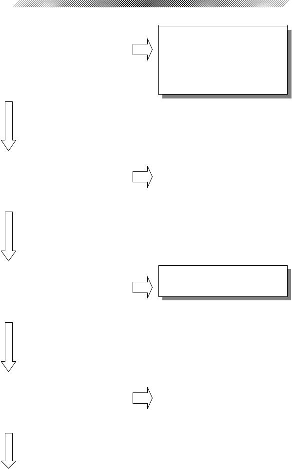
§2 TROUBLESHOOTING
|
Turn the system on. |
Does the |
|
No |
|
|
|||
|
initialization start without the Err at |
|
||
|
|
|
||
|
the startup? |
|
|
|
|
(The Err appears at the AR or KM |
|
|
|
|
measurement, or the measured value is |
|
|
|
|
out of the standard.) |
|
|
|
|
|
|
|
|
|
|
|
|
|
|
Yes |
|
|
|
A board etc. may fall because of the malfunction other than the adjustment.
Repair the system according to the AR-600/ARK-700 series Service Manual (No. MAR10RTZ001).
|
Perform the AR measurement with a |
|
No |
|
3.1 Can Not Perform the AR |
|
|
|
|
|
|||
|
model eye and a human eye. |
|
|
|
Measurement Normally. |
|
|
Can the AR measurement be |
|
|
|
|
|
|
performed normally? |
|
|
|
|
|
|
|
|
|
|
|
|
|
|
|
|
|
|
|
|
|
|
|
|
|
|
|
Yes |
|
|
|
|
|
|
Perform the KM measurement with a |
|
No |
3.2 Can Not Perform the KM |
|
|
|||
|
KM steel ball. |
|
|
Measurement Normally. |
|
Can the KM measurement be |
|
|
|
|
performed normally? |
|
|
|
|
|
|
|
|
|
|
|
|
|
|
Yes |
|
|
|
|
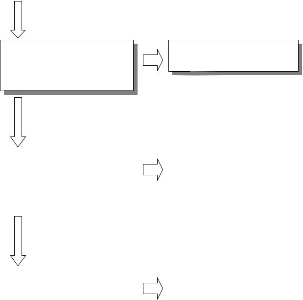
Measure the model eye while the auto- |
|
No |
|
Perform the auto-tracking adjustment. |
|
|
|
|
|
|||
|
tracking function is on. |
|
|
|
(See 4.18.) |
|
|
Does the auto-tracking function work |
|
|
|
|
|
|
normally? |
|
|
|
|
|
|
|
|
|
|
|
|
|
|
|
|
|
|
|
|
|
|
|
|
|
|
Yes
 2 - 2
2 - 2
Measure the model eye while the autoshot function is on.
Does the auto-shot function work normally?
Yes
No Adjust the auto-shot function. (See 4.19.)
|
Does the chart work normally at the |
|
No |
|
Perform the chart calibration. |
|
||
|
|
|
|
|||||
|
AR or KM measurement? |
(Pressing |
|
|
|
(See 4.11.) |
|
|
|
the start button brings the chart into |
|
|
|
(As for the AR-660A/ARK-760A, see |
|
||
|
focus. |
Then the view |
is fogged |
|
|
|
4.20.) |
|
|
automatically.) |
|
|
|
|
|
|
|
|
|
|
|
|
|
|
|
|
|
|
|
|
|
|
|
|
|
|
|
|
|
|
|
|
|
|
|
|
Yes |
|
|
|
|
|
|
|
Measure a PD. |
|
No |
|
Perform the PD adjustment. |
|
|
|
|
|
|||
|
Is the measured PD within the |
|
|
|
(See 4.17.) |
|
|
standard? |
|
|
|
|
|
|
|
|
|
|
|
|
|
|
|
|
|
|
|
|
|
|
|
|
|
|
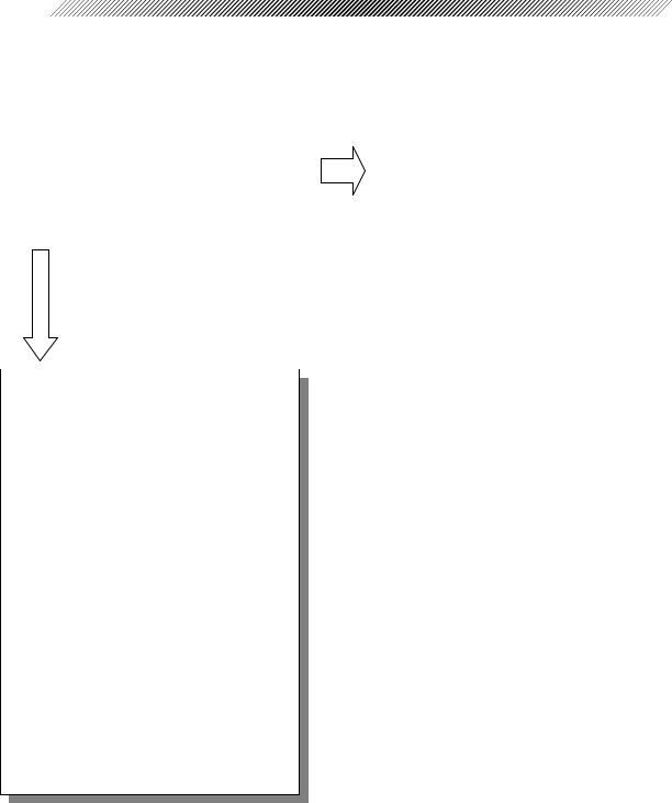
§3 SUB TROUBLESHOOTING
3.1 Can Not Perform the AR Measurement Normally.
|
Measure the model eye. |
|
|
No |
|
The SPH value is out of the standard. |
|
||
|
|
|
|
|
|||||
|
Can the measure be performed even if |
|
|
|
→ Perform the SPH calibration. |
|
|||
|
the measured value is out of the |
|
|
|
(See 4.7.) |
|
|||
|
standard? |
|
|
|
|
|
|
|
|
|
|
|
|
|
|
The CYL value is out of the standard. |
|
||
|
|
|
|
|
|
→ Check and repair the system in the |
|
||
|
Yes |
|
|
|
|
||||
|
|
|
|
|
following order. |
|
|||
|
|
|
|
|
|
4.5 |
CYL Value Adjustment |
|
|
|
|
|
|
|
|
4.6 |
Measurable Range Adjustment |
|
|
|
|
|
|
|
|
4.7 |
SPH Value Calibration |
|
|
|
|
|
|
|
|
4.8 AR AXIS Adjustment |
|
||
|
Check and perform the adjustment in |
|
4.9 |
Microcoria Check |
|
||||
|
the following order. |
|
|
|
|
4.10 |
IOL Check |
|
|
|
4.3 Three-Point Relation |
among |
|
4.11 Chart Calibration |
|
||||
|
SPD, Mask and LED |
|
|
|
|
4.12 |
Internal Reflection Check |
|
|
|
(* When the three-point relation |
|
4.18 |
Auto-Tracking Adjustment |
|
||||
|
is misaligned widely in the item |
|
4.19 |
Auto-Shot Adjustment |
|
||||
|
4.3, perform the adjustment in |
|
|
|
|
|
|||
|
|
|
|
|
|
||||
|
the order of 4.1 → 4.2 → |
4.3.) |
|
|
|
|
|
|
|
4.5CYL Value Adjustment
4.6Measurable Range Adjustment
4.7SPH Value Calibration
4.8AR AXIS Adjustment
4.9Microcoria Check
4.10IOL Check
4.11Chart Calibration
4.12Internal Reflection Check
4.18Auto-Tracking Adjustment
4.19Auto-Shot Adjustment
 3 - 2
3 - 2
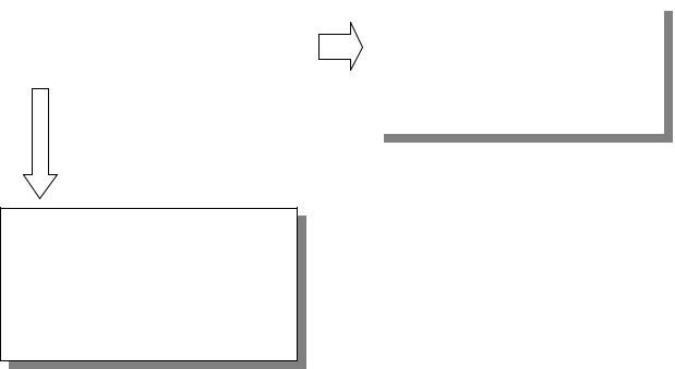
3.2 Can Not Perform the KM Measurement Normally.
|
Can the KM measurement be |
|
Yes |
The KM measurement can be |
|
|
|||
|
performed? |
|
|
performed, but the measured value is |
|
|
|
|
out of the standard. |
|
|
|
|
→ Perform the KM calibration. |
|
No |
|
||
|
|
(See 4.14.) |
||
|
|
|
|
|
The KM optical axis is misaligned. Check and adjust it in the following order.
4.13KM Optical Axis Adjustment
4.14KM Calibration
4.15KM Axis Check and Correction

§4 ADJUSTMENT
4.1Optical Axis Adjustment of Phototransmitter /Photoreceptor
[Optical axis check of phototransmitter/photoreceptor]
1.Attach a lamp in front of the SPD holder to illuminate the photoreceptor.
2.Put a piece of white paper in front of the LED.
3.Attach the optical axis adjustment jig (ARMJ-7).
4.Turn the SPD holder to make the photoreceptor horizontal.
Optical axis adjustment jig
A piece of white paper
SPD holder
Lamp
5.If the positions of the photoreceptor and aperture are not as the right figure shows, perform the [Optical axis adjustment of phototransmitter/photoreceptor].
Aperture
Photoreceptor
[Optical axis adjustment of phototoransmitter/phototreceptor]
First, align the photoreceptor height.
1.Turn the holder of G13 to align the photoreceptor height at –12D with the aperture.
*See Figure on page 4-3 for the –12D position.
|
|
|
|
|
|
|
|
|
Holder of G13 |
|
|
|
|
|
|
|
|
|
|
|
|
|
|
|
|
|
|
|
|
|
|
|
|
|
|
|
|
|
|
|
Aperture |
||||||||
|
|
|
|
|
|
|
|
|
|
|
|
|
|
|
|
|
|
|
|
|
|
|
|
|
|
|
|
|
|
|
|
|
|
||||||||||||||||
|
|
|
|
|
|
|
|
|
|
|
|
|
|
|
|
|
|
|
|
|
|
|
|
|
|
|
|
|
|
|
|
|
|
|
|
|
|
|
|
|
|
|
|
|
|
|
|
|
|
|
|
|
|
|
|
|
|
|
|
|
|
|
|
|
|
|
|
|
|
|
|
|
|
|
|
|
|
|
|
|
|
|
|
|
|
|
|
|
|
|
|
|
|
|
|
|
|
|
|
|
|
|
|
|
|
|
|
|
|
|
|
|
|
|
|
|
|
|
|
|
|
|
|
|
|
|
|
|
|
|
|
|
|
|
|
|
|
|
|
|
|
|
|
|
|
|
|
|
|
|
|
|
|
|
|
|
|
|
|
|
|
|
|
|
|
|
|
|
|
|
|
|
|
|
|
|
|
|
|
|
|
|
|
|
|
|
|
|
|
|
|
|
|
|
|
|
|
|
|
|
|
|
|
|
|
|
|
|
|
|
|
|
|
|
|
|
|
|
|
|
|
|
|
|
|
|
|
|
|
|
|
|
|
|
|
|
|
|
|
|
|
|
|
|
|
|
|
|
|
|
|
|
|
|
|
|
|
|
|
|
|
|
|
|
|
|
|
|
|
|
|
|
|
|
|
|
|
|
|
|
|
|
|
|
|
|
|
|
|
|
|
|
|
|
|
|
|
|
|
|
|
|
|
|
|
|
|
|
|
|
|
|
|
|
|
|
|
|
|
|
|
|
|
|
|
|
|
|
|
|
|
|
|
|
|
|
|
|
|
|
|
|
|
|
|
|
|
|
|
|
|
|
|
|
|
|
|
|
|
|
|
|
|
|
|
|
|
|
|
|
|
|
|
|
|
|
|
|
|
|
|
|
|
|
|
|
|
|
|
|
|
|
|
|
|
|
|
|
|
Photoreceptor
Holder of G8+G9+G10
2.Turn the holder of G8+G9+G10 to align the photoreceptor height at +12D with the
aperture center.
3.Repeat Step 1 and 2 to align the photoreceptor height with the aperture center.
[Adjustment of photoreceptor in horizontal direction]
1. Turn the SPD holder 90º to make the photoreceptor vertical.
2. Move G13 to make a horizontal alignment |
At +12D |
of the photoreceptor at +12D and –12D |
|
|
|
with the aperture. |
|
* Turn G13 at –12D and move parallel at |
|
+12D. |
|
|
|
|
At –12D |
3.Repeat Step 2 until the photoreceptor is horizontally aligned with the aperture center.
[Important]
1.Tighten the set screws (n=3) on the top of G13 holder evenly, paying attention to the displacement in the horizonal direction.
2.If there is a displacement in the vertical direction, make an adjustment by turning G13 holder again.
3. G13 is not out of the holder.
4. Turn the SPD holder and make sure that the photoreceptor is always at the aperture center.
4 - 2
Photoreceptor
Aperture 
4 - 3
4.2 Optical Axis Adjustment of Chart
[Optical axis check of chart]
1.Attach the illumination jig in front of the SPD holder to illuminate the photoreceptor.
2.Put a piece of white paper in front of the measuring LED.
3.Attach the optical axis adjustment jig (ARMJ-7).
4.Set the DIP switch No.4 to the ON position and turn the system on.
5.Press  (IOL button).
6.Look into G8+G9+G10 through the –12D magnifier and move the sensor carry until the chart is focused.
<Reference>
• Where both the chart and aperture of the sensor carry are focused, looking into G8+9+10
|
with the naked eye. |
0D position |
• |
Where both the chart and aperture of the sensor carry are focused, looking into G8+9+10 |
|
|
with the +012D magnifier. |
–12D position |
• |
Where both the chart and aperture of the sensor carry are focused, looking into G8+9+10 |
|
|
with the –12D magnifier. |
+12D position |
G6+G7

 Sensor carry
G8+G9+G10
3130 (chart)
–12D |
0D |
+12D |
4 - 4
When adjusting the optical axis of the chart, adjust the chart in vertical direction.
[Adjustment of chart in vertical direction]
1.Turn the holder of G6+G7 to align the chart height at +12D and –12D with the aperture center.
*Check at 0D posiiton, as well.
Aperture
Chart
G6 + G7
G6+G7
Adjust the chart in horizontal direction.
[Adjustment of chart in horizontal direction]
1.Move G6 + G7 parallel as the right figure shows to align the chart at –12D with the
aperture center.
2.Turn G6 + G7 as the right figure shows to align the chart at +12D with the aperture center.
Chart Aperture
Repeat Step 1 and 2 until the chart is horizontally aligned with the aperture center.

4 - 5
[Important]
1.When G6 + G7 is fixed with set screws, there may be a displacement in both vertical and horizontal directions.
In such a case, tighten the screws paying attention to the horizontal direction and turn the holder again if there is a displacement in the vertical direction.
2.The screws (n=3) retaining G6 + G7 shall be tightened evenly.
3.The prism of G6 + G7 is not out of the front of the holder.
3.Move the entire chart unit until the balloon center is placed within 1/4 of the aperture.
 4 - 6
4 - 6
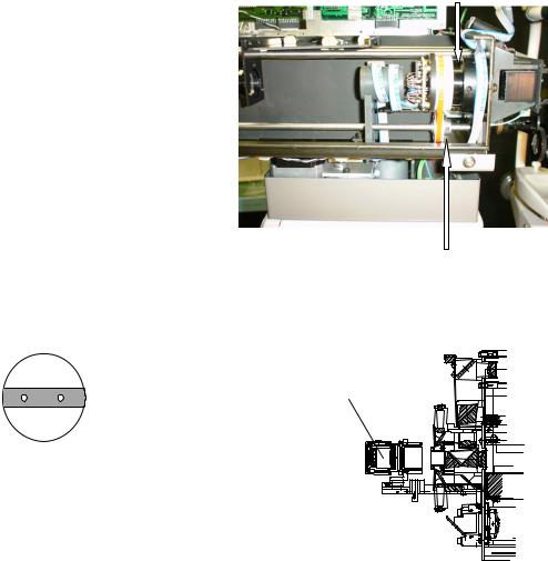
4.3 Three-Point Relation among SPD, Mask and LED
4.3.1 Check of three-point relation among SPD, mask and LED
1.Remove the shield plate.
*The right figure shows ARK-700 series.
In the AR-600 series, the shield plate is removed in the same manner.
2.Remove the LED base L.
*The right figure shows ARK-700 series.
In the AR-600 series, the LED base L is removed in the same manner.
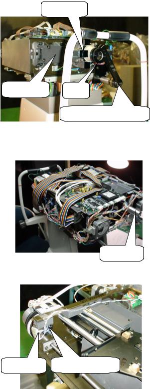
3.Attach the optical axis adjustment jig (ARMJ-7) on the measuring unit with PC4×14.
*Remove the cable cramp.
*Attach the jig so as not to crush the cable.
*Adjust the length of the arm by pushing or pulling the arm so that two magnifiers and the mire (measuring window) will be placed in a straight line.
*The front one is a magnifier of the + power.
4.Remove EA15 (chart LED) on 3130 (chart).
*The SPD photoreceptor cannot be seen unless the chart LED is turned off.
*The chart LED is used for illuminating the SPD photoreceptor.
*If the SPD photoreceptor is illuminated by a pen light, etc., you may disconnect J17 on the PC6 board to turn off the chart LED.
5.Set the chart LED removed in the previous step in front of the SPD photoreceptor with a tape, etc.
*Illuminating the SPD photoreceptor allows you to see an element easily.
*If it is hard to see with the chart LED, use a pen light, etc.
LED base L
Shield plate |
Mire |
|
Optical axis adjustment jig |
Chart LED
Chart LED |
SPD photoreceptor |
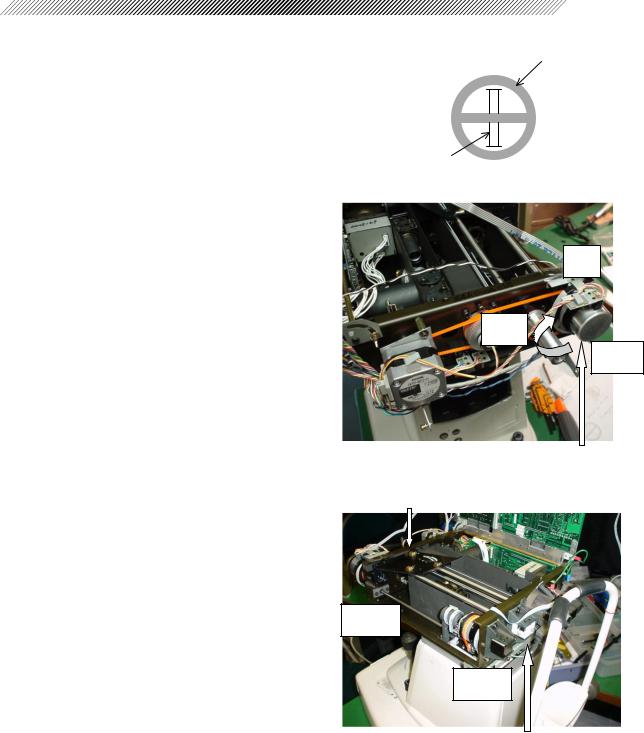
In Step 6 and 7, make sure that the SPD and mask photoreceptors are perpendicular as the right figure shows.
SPD photoreceptor
4 - 7
Mask photoreceptor
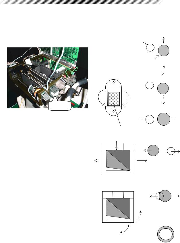
6.Set the sensor plate on 5047 (SPD unit) at the 0º position (top).
*The mask photoreceptor can be seen by looking into G6 + G7 with the naked eye.
0º
90º
180º
7.Move 5035 (sensor carry) to the + side to bring the SPD photoreceptor into focus.
*Look into G6 + G7 with the naked eye and make sure that the SPD and mask photoreceptors are perpendicular.
Turn the SPD unit in the direction of the arrow.
Sensor carry
– side
+ side
Look into 1651 (G6+G7) with naked eye.
When the SPD and mask photoreceptors are not perpendicular, perform “4.3.2 Perpendicular adjustment of SPD and mask photoreceptors”.
 4 - 8
4 - 8
4.3.2 Perpendicular adjustment of SPD and mask photoreceptors
1.Loosen HH3×4 (n=2) retaining 5041 (timing pulley).
*The SPD unit and mask unit turn seperately.
2.Set the shutter on 5047 (SPD unit) at the 0º position (top).
Mask unit
3.Turn the mask unit so that the SPD and mask photoreceptor will be perpendicular.
4.Tighten HH3×4 (n=2) retaining 5041 (timing pulley).
HH3×4 (n=2) retaining timing pulley
When the SPD and mask photoreceptors become to be perpendicular, attach the LED adjustment jig (RKDJ-1) to make sure that the LED lights are parallel to the mask photoreceptor.
HH35B
LED adjustment jig (RKDJ-1) |
LED lights are parallel to mask photoreceptor.
*If the LED adjustment jig (RKDJ-1) is not available, it may use the optical axis adjustment jig (ARMJ-7).
SB3IB |
When the LED lights are not parallel to the mask photoreceptor, perform “4.3.3 Tilt adjustment of LED lights and mask photoreceptor”.
 Loading...