


NIDEK
AUTO REF/KERATOMETER
ARK-30
Type R
OPERATOR’S MANUAL

NIDEK CO., LTD. |
: 34-14, Maehama, Hiroishi-cho, Gamagori, Aichi 443-0038, Japan |
(Manufacturer) |
Telephone: (0533) 67-6611 |
|
Facsimile: (0533) 67-6610 |
NIDEK CO., LTD |
: 6th Floor, Takahashi Bldg., No.2, 3-chome, Kanda-jinboucho |
(Tokyo Office) |
Chiyoda-ku, Tokyo 101-0051, Japan |
|
Telephone: (03) 3288-0571 |
|
Facsimile: (03) 3288-0570 |
|
Telex: 2226647 NIDEK J |
NIDEK INCORPORATED |
: 47651 Westinghouse Drive Fremont, California 94539, U. S. A. |
(United States Agent) |
Telephone: (510) 226-5700 |
|
Facsimile: (510) 226-5750 |
NIDEK SOCIETE ANONYME |
: Europarc 13, rue Auguste Perret, 94042 CRETEIL, France |
(Authorized Representative) |
Telephone: (01) 49 80 97 97 |
|
Facsimile: (01) 49 80 32 08 |
2005.1
32725-P902G Printed in JAPAN
 BEFORE USE OR MAINTENANCE, READ THIS MANUAL.
The Operator’s Manual contains information necessary for the operation of the NIDEK AUTO REF/KERATOMETER Model ARK-30.
This manual includes operating procedures, cautions for safety, and specifications. The device complies with ISO 10342 (Ophthalmic instruments - Eye refractometers). IEC and UL standards are applied in this manual. The dioptric powers are indicated with reference wavelength λd = 587.56 nm. For correct use, this manual is needed. Especially, the cautions for safety and operating procedures must be thoroughly understood before using the device. Keep this manual handy to verify use whenever necessary.
There are no user-serviceable parts inside the device except the printer paper, fuse, and battery. If you encounter any problems or have questions about the device, contact your authorized distributor.
(This applies only to the equipments whose power source is 100/120Vac.)

Table of Contents
§1 INTRODUCTION |
Page |
|
1-1 |
||
1.1 |
Outline of the Device ............................................................................................... |
1-1 |
1.2 |
Indications for Use ................................................................................................... |
1-1 |
1.3 |
Classifications .......................................................................................................... |
1-1 |
1.4 |
Symbol Information ................................................................................................. |
1-2 |
§2 SAFETY ........................................................................................................................ |
2-1 |
|
2.1 |
Cautions during Use ................................................................................................. |
2-1 |
2.2 |
Storage ...................................................................................................................... |
2-6 |
2.3 |
Transport................................................................................................................... |
2-6 |
2.4 |
Installation ................................................................................................................ |
2-7 |
2.5 |
Wiring ....................................................................................................................... |
2-8 |
2.6 After Use .................................................................................................................. |
2-8 |
|
2.7 |
Maintenance and Checks .......................................................................................... |
2-9 |
2.8 |
Disposal .................................................................................................................... |
2-9 |
2.9 |
Labels ..................................................................................................................... |
2-10 |
§3 CONFIGURATION ..................................................................................................... |
3-1 |
|
§4 OPERATING PROCEDURES.................................................................................... |
4-1 |
|
4.1 |
Operation Flow ......................................................................................................... |
4-1 |
4.2 |
Before First Use ....................................................................................................... |
4-1 |
4.3 |
Measuring Procedures .............................................................................................. |
4-4 |
4.4 AR (refractive error) & KM (corneal curvature radius) Measurements (R/K mode) .... |
||
...................................................................................................................................... |
|
4-18 |
4.5 AR (refractive error) Measurement (R mode) ........................................................ |
4-20 |
|
4.6 |
KM (corneal curvature radius) Measurement (K mode) ........................................ |
4-22 |
4.7 |
90º Angle Correction Function ............................................................................... |
4-24 |
4.8 |
Measurement Using Cable ..................................................................................... |
4-26 |
4.9 |
Storing and Printing Measured Results .................................................................. |
4-28 |
|
4.9.1 Storing measured results ............................................................................... |
4-28 |
|
4.9.2 Printing stored data ....................................................................................... |
4-30 |
|
4.9.3 Clearing measured results in memory ........................................................... |
4-32 |
|
4.9.4 Confirming measured results in memory ...................................................... |
4-33 |
4.10 Connection with External Devices ....................................................................... |
4-34 |
|
|
4.10.1 Output to the RT or computer ..................................................................... |
4-34 |
|
4.10.2 Input from the LM ....................................................................................... |
4-36 |
|
4.10.3 Output to the IC card Reader/Writer ........................................................... |
4-38 |

|
|
Page |
|
4.10.4 Output to the IC card Reader/Writer (EyeCa-RW) ..................................... |
4-40 |
4.11 Sagittal Radius Measurement ............................................................................... |
4-42 |
|
§5 PRINTOUT ................................................................................................................... |
5-1 |
|
5.1 |
Printing Measured Values ......................................................................................... |
5-1 |
5.2 |
Other Prints .............................................................................................................. |
5-5 |
|
5.2.1 Printout sample of stored data ......................................................................... |
5-5 |
|
5.2.2 Printout sample of parameter .......................................................................... |
5-6 |
§6 OTHER FUNCTIONS ................................................................................................. |
6-1 |
|
6.1 |
Parameter Settings .................................................................................................... |
6-1 |
6.2 |
Setting Date and Time .............................................................................................. |
6-9 |
6.3 |
Entering Comments ................................................................................................ |
6-11 |
§7 §8
§9
TROUBLESHOOTING GUIDE ................................................................................ |
7-1 |
|
MAINTENANCE ......................................................................................................... |
8-1 |
|
8.1 |
Replacing Printer Roll .............................................................................................. |
8-1 |
8.2 Installing/Removing Battery .................................................................................... |
8-3 |
|
8.3 Charging Battery ...................................................................................................... |
8-4 |
|
8.4 Attaching/Detaching the Strap.................................................................................. |
8-6 |
|
8.5 Attaching the Eye Mask ........................................................................................... |
8-8 |
|
8.6 |
Replacing Fuses........................................................................................................ |
8-9 |
8.7 |
Cleaning the Measuring Window ........................................................................... |
8-10 |
8.8 |
Cleaning Exterior ................................................................................................... |
8-11 |
8.9 |
Lists of Replacement Parts ..................................................................................... |
8-11 |
SPECIFICATIONS ...................................................................................................... |
9-1 |
|
§10ACCESSORIES .......................................................................................................... |
10-1 |
10.1 Standard Accessories ............................................................................................ |
10-1 |
10.2 Optional Accessories ............................................................................................ |
10-1 |
§11EMC (ELECTROMAGNETIC COMPATIBILITY) .............................................. |
11-1 |
APPENDIX. A GLOSSARY ................................................................................................. |
A-1 |
INDEX ........................................................................................................... |
End of this manual |
[This page is intentionally left blank.]

§1 INTRODUCTION
1.1 Outline of the Device
The NIDEK Auto Ref/Keratometer ARK-30 is an objective refraction measurement device that contains the functions for measuring refractive errors such as spherical power, cylindrical power, and cylinder axis and the functions for measuring corneal shapes such as the corneal curvature radius (corneal refractive power), angle of meridian, and corneal cylindrical power.
The measured value of refractive errors are mainly used as the reference of the lens prescription for correction of visual acuity in spectacle and contact lenses. The measured value of the corneal curvature is used for the prescription of visual acuity corrective lenses such as contact lenses. It is also used to observe the corneal curvature radius necessary for setting the refractive power of intraocular lens that will be implanted after cataract surgery and the change process of the postoperative corneal shape after corneal surgery.
This device is a hand-held type that allows children who cannot fix their head on the stationary chinrest and lying patients to be measured. As well as the compact station, the device can be easily moved, which makes the measurement possible in a sick room or operating room where the measurement is not possible with the stationary type.
The device consists of a measuring unit and a station. The station is provided with a power supply, a charger, and a printer to print the measured results. The measuring unit is provided with a color LCD monitor and a control panel, etc. to perform alignment and operation.
To make the measurements easier, an auto-shot function is available, which will start the measurement automatically when the patient’s eye is aligned and focused.
The built-in RS-232C interface allows you to output data to a personal computer.
1.2 Indications for Use
The Model ARK-30 Auto Ref/Keratometer is a diagnostic device that is indicated for use in the automated measurement of refractive errors of the eye, and in the measurement of the corneal curvature of the eye.
1.3 Classifications
[Classification under the provision of 93/42EEC (MDD)] Class IIa
The ARK-30 is classified as a Class IIa device.
[Form of protection against electrical shock] Class I
The ARK-30 is classified as a Class I device. The Class I device is a device in which protection against electric shock does not rely solely on basic insulation. The Class I device includes additional safety precaution that provides for a connection of accessible conductive parts to a protective (earth) grounding conductor in the fixed wiring of the installation.
Use a power outlet which is equipped with a ground terminal.
1 - 2
[Degree of protection against electrical shock] Type B applied part
The ARK-30 is provided with a Type B applied part.
The Type B applied part provides an adequate degree of protection against electrical shock, particularly regarding the following:
-allowable leakage currents
-reliability of the protective earth ground connection (if applicable)
[Degree of protection against liquid entry] IP20*1
The ARK-30 is classified as a normal device, as such provides only minimal protection against liquid intrusion.
Avoid splashing water or another liquid on or in the device.
[Degree of protection against flammability]
The ARK-30 is classified as a device not suitable to be used in a potentially flammable environment.
Do not operate the device near flammable type materials.
[Method (s) of sterilization or disinfection recommended by the manufacturer]
The forehead rest can be cleaned with a cloth dampened with rubbing alcohol as necessary.
[Mode of operation]
Classification of the ARK-30: Continuous operation
1.4 Symbol Information
This symbol on the device indicates that caution must be taken.
Refer to the operator’s manual before use.
This symbol indicates that the degree of protection against electrical shock of the applied part is classified as a Type B applied part.
This symbol on the control panel indicates the start button for placing the device in the measurement mode.
This symbol on the control panel indicates the power button for turning the measuring unit on and off. Pressing the button turns the measuring unit on and off.
*1 In accordance with IEC 60529


 1 - 3
1 - 3
This symbol on the station indicates that the power is on.
This symbol on the station indicates that the power is off.
This symbol on the control panel indicates the print button for transmitting the measured results to the station for printing out.
On the station, this symbol indicates the feed button for feeding the printer paper.
This symbol on the control panel indicates the parameter button for displaying the menu to change the settings on the screen.
This symbol on the control panel indicates the memory button to store the median values of the measured results.
On the station, the illuminated lamp for this symbol indicates that AR and KM data that will be outputted externally are being stored in memory.
This symbol on the control panel indicates the angle correction button for rotating the measuring optical axis 90°.
This is the symbol on the control panel and station. The lamp with this symbol flashes while the battery is being charged.
This symbol indicates the fuse rating.
This symbol indicates that the device must be supplied only with alternating current.
This symbol indicates the connection part that is suitable for direct current only.
This indicates the input part.
This indicates the output part.
This symbol on the station indicates that power is supplied to the station and the power switch is turned on when the lamp with this symbol is illuminated.

§2 SAFETY
In this manual, a Signal Word is used to designate the degree or level of safety alerting. The definition is as follows:
 CAUTION: Indicates a potentially hazardous situation which, if not avoided, may result in minor or moderate injury or property damage accident.
Even situations indicated by “ CAUTION” may result in serious injury under certain conditions. Safety precautions must be strictly followed at all times.
2.1 Cautions during Use
 CAUTION
• Do not modify or touch the inside of the device.
This may result in an electric shock or a malfunction.
• Do not dismantle or modify the battery.
Heat generation, explosion, or combustion may result.
• Never remove the power cord from the wall outlet by holding on to the cord.
This may damage the cord and cause a short circuit or an electric shock. Grasp the plug then pull.
•Do not place heavy objects on the power cord to prevent damage to the power cord, and a fire or an electric shock.
•Immediately replace the power cord if the internal wires are exposed, the device power turns on or off when the power cord is moved, or the cord and/or plug becomes extremely hot.
This may result in an electric shock or a fire.
•Do not use the device for other than the intended purpose.
NIDEK will not be responsible for accidents or a malfunction caused by carelessness.
• Wipe between the prongs of the main plug with a dry cloth every once in a while.
If dust settles between the prongs, the dust will collect moisture, and a short circuit or a fire may occur.
• Before measuring a patient, wipe the forehead rest with a clean cloth.
If necessary, wipe the forehead rest with a cloth dampened with rubbing alcohol.


 2 - 2
2 - 2
 CAUTION
•In the event of a malfunction, do not touch the inside of the device, but disconnect the power cord from the wall outlet and contact your authorized distributor.
•There may be cases where a measuring eye (R/L) is not detected correctly, depending on the shape of the patient’s face.
Change the setting by pressing the R/L selection button 
 if the indication of the measuring eye side is not correct.
•When moving the device with your hand, use the hand strap or neck strap (option). To move the device, be sure to hold the grip. Do not hold the hand strap only.
Accidentally dropping the device may cause an injury or a malfunction.
For a malfunction caused by dropping the device, the warranty is not valid. You must pay to repair the device.
•Bring the device to the patient’s face after drawing out the forehead rest.
The device may contact the patient’s face.
•Keep the measuring window free of fingerprints and dust to prevent the measurement accuracy from decreasing.
•The date and time may deviate if the battery is removed from the measuring unit for more than 12 hours. In this situation, reset the date and time.
•The measured values of objective refractive power obtained by the ARK-30 are intended to be used as a reference of lens prescription for the correcton of visual acuity with spectacle or contact lenses. Manifest refraction must be used as the basis for the spectacle or contact lens prescription.

2 - 3
 CAUTION
•Information on the avoidance of overexposure to potentially hazardous optical radiation (ISO 15004: 1997)
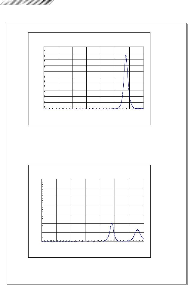
Spectrally weighted photochemical radiances LB and LA give a measure of the potential that exists for a beam of light to cause photochemical hazard to the retina. LB gives the measure for eyes in which the crystalline lens is in place. LA gives this measure either for eyes in which the crystalline lens has been removed (aphakes) and has not been replaced by a UV-blocking lens or for the eyes of very young children.
The value stated for this ophthalmic device gives a measure of hazard potential when the device is operated at maximum intensity and maximum aperture. The values of LA or LB for the ARK-30 are sufficiently low as shown on the following page.
The retinal exposure dose for a photochemical hazard is a product of the radiance and the exposure time. For instance, at a radiance level of 0.5 mW/(cm2•sr), 480 min irradiation of the dilated (8 mm diameter) pupil would cause the retinal exposure dose level to attain the recommended exposure limit. If the value of radiance were reduced to 0.05 mW/(cm2•sr), ten times that time (i.e. 4800 min) would be needed to reach the recommended limit. The recommended exposure dose is based on calculations arising from the American Conference of Governmental Industrial Hygienists (ACGIH) - Threshold Limit Values for Chemical Substances and Physical Agents (1995 - 1996 edition).
The following page shows the graph of spectrum output for the ARK-30. Patients will be at low risk of acute optical radiation with the ARK-30. However, it is recommended that the intensity of light directed into the patient’s eye be limited to the minimum level which is necessary for diagnosis. The total of the retinal exposure dose must be carefully watched for infants, aphakes and persons with diseased eyes who are at greater risk when other ophthalmic devices with a high level of radiance are used in conjunction.


 2 - 4
2 - 4
 CAUTION
Spectrum output of all light source during AR measurement (maximum light intensity)
|
|
|
|
AR-20/ARK-30 |
|
|
|
|
|
|
|
|
ARK-30 |
|
|
|
|
|
10 |
|
|
|
|
|
|
|
|
9 |
|
|
|
|
|
|
|
) |
8 |
|
|
|
|
|
|
|
7 |
|
|
|
|
|
|
|
|
(μW/c |
|
|
|
|
|
|
|
|
6 |
|
|
|
|
|
|
|
|
5 |
|
|
|
|
|
|
|
|
|
|
|
|
|
|
|
|
|
4 |
|
|
|
|
|
|
|
|
Irradi- |
|
|
|
|
|
|
|
|
3 |
|
|
|
|
|
|
|
|
ance: |
|
|
|
|
|
|
|
|
|
2 |
|
|
|
|
|
|
|
|
1 |
|
|
|
|
|
|
|
|
0 |
|
|
|
|
|
|
|
|
300 |
400 |
500 |
600 |
700 |
800 |
900 |
1000 |
|
|
|
Wavelength: (nm) |
|
|
|
||
Spectrum irradiance
*1 LA (µW/cm2/sr) 380 - 700 nm |
0.527 |
*2 LB (µW/cm2/sr) 305 - 700 nm |
0.056 |
Spectrum output of all light source during KM measurement (maximum light intensity)
|
|
|
|
AR-20/ARK-30 |
|
|
|
|
|
|
|
|
ARK-30 |
|
|
|
|
|
7 |
|
|
|
|
|
|
|
|
6 |
|
|
|
|
|
|
|
) |
5 |
|
|
|
|
|
|
|
(μW/c |
|
|
|
|
|
|
|
|
4 |
|
|
|
|
|
|
|
|
3 |
|
|
|
|
|
|
|
|
|
|
|
|
|
|
|
|
|
|
2 |
|
|
|
|
|
|
|
Irradiance: |
|
|
|
|
|
|
|
|
|
1 |
|
|
|
|
|
|
|
|
0 |
|
|
|
|
|
|
|
|
300 |
400 |
500 |
600 |
700 |
800 |
900 |
1000 |
Wavelength: (nm)
|
|
Spectrum irradiance |
|
|
|
|
|
|
|
|
|
|
|
|
|
|
|
|
|
|
µ |
|
|
|
|
|
|
|
|
*1 LA ( W/cm2/sr) 380 |
- 700 nm |
0.002 |
|
|
|
|
|
|
*2 LB (µW/cm2/sr) 305 |
- 700 nm |
0.030 |
|
|
|
|
|
|
|
|
|
|
|
|
|
|
|
|
|
|
|
|
|
|
|
|
|
|||||
*1 |
|
LA: Spectrally weighted photochemical aphakic source radiance |
||||||
*2 |
|
LB: Spectrally weighted photochemical phakic source radiance |
||||||
2 - 5
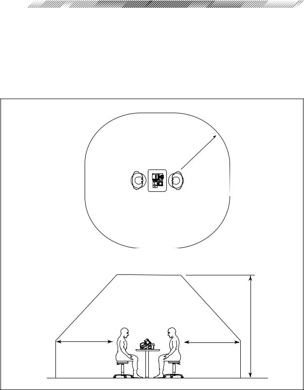
{ Patient environment
The patient environment represents a space where there is a possibility of direct contact between the patient or the operator and third person.
When another type of device is used in the patient environment, use a device that complies with IEC 60601-1. If the devices that do not comply with IEC 60601-1 are used, it is necessary to use an isolating transformer to power the device or to connect the devices to additional protective grounding.
Radius of 1.5 m
2.5 m
1.5 m |
1.5 m |


 2 - 6
2 - 6
2.2 Storage
 CAUTION
•Store the device in a place that is dry and free from poisonous gas.
•The device must be maintained under the following conditions during transport and storage (packed condition).
Environmental conditions |
Temperature: |
–20ºC to 60ºC |
|
Humidity: |
10% to 95% (No condensation) |
|
A place with low dust |
|
|
A place not exposed to direct sunlight |
|
2.3 Transport
 CAUTION
•Do not drag the cord or cables when moving the device to prevent an injury or a malfunction.
•Place the device in the shipping carton or optional carrying case when moving to another location. Do not use the carrying case if you ask the moving company to take care of the device.
Excessive vibration or impact may cause a device malfunction.
2.4Installation
 CAUTION
• Do not install the device near water.
Keep water away from the device to prevent an electric shock or a malfunction.
•Install the device on a stable and level surface free from vibration and impact to prevent a malfunction or an injury caused by knocking over the device.
•For printing, wireless communication is performed using infrared beams from the measuring unit to the station. Install the device where the light-receiver window of the station is not exposed to intense light such as sunlight and illumination that contains infrared rays.
If the intense external light comes into the light-receiver window, printing may not be performed correctly. Cut off sunlight with a curtain and turn off nearby illumination.

2 - 7
 CAUTION
• Install the device in an environment that meets the following conditions.
Conditions in use |
Temperature: |
10ºC to 40ºC |
|
Humidity: |
30% to 75% (No condensation) |
|
Pressure: |
700 hPa to 1060 hPa |
|
A place with little dust |
|
|
A place with little external light |
|
|
A place free of vibration and impact |
|
•This device complies with the limits for medical devices in IEC60601-1-2: 2001, EN60601- 1-2: 2001, and Medical Device Directive 93/42/EEC. These limits are designed to provide reasonable protection against harmful interference in a standard medical installation. This device generates, uses and can radiate radio frequency energy and, if not installed and used in accordance with the instructions, may cause harmful interference to other devices in the vicinity. However, there is no guarantee that interference will not occur in a particular installation. If this device does cause harmful interference to other devices, which can be determined by turning the device off and on, the user is encouraged to try to correct the interference by one or more of the following measures:
-Reorient or relocate the receiving device.
-Increase the distance to the device.
-Correct the device into an outlet on a circuit different from that to which the other device (s) are connected.
-Consult the manufacturer or field service technician for assistance.
•In installation and operation of the device, observe the following instructions about EMC (electromagnetic compatibility):
-Do not use the device simultaneously with other electronic equipment to avoid electromagnetic interference with the operation of the device.
-Do not use the device near, on, or under other electronic equipment to avoid electromagnetic interference with the operation of the device.
-Do not use the device in the same room with other equipment such as life-support equipment, other equipment that has major affects on the life of the patient and results of treatment, or other measurement or treatment equipment that involves small electric current.
-Do not use the device simultaneously with portable and mobile radio frequency communication systems because it may have an adverse effect on operation of the device.
-Do not use cables and accessories that are not specified for the device because that may increase the emission of electromagnetic waves from the device or the system and decrease the immunity of the device to electromagnetic disturbance.
•The Electromagnetic Compatibility Directive sets the essential requirements for electrical and electronic equipment that may disturb, or be disturbed by, other equipment. The ARK30 complies with these requirements as tabled on pages 11-1 to 11-3. Follow the guidance in the tables for use of the device in an electromagnetic environment.


 2 - 8
2 - 8
2.5 Wiring
 CAUTION
• Be sure to use a wall outlet which meets the requirements of the power specification. If the line voltage is too high or too low, the device may not give full performance. A malfunction or a fire may occur.
•Do not put many loads on one electrical outlet. A fire may occur.
•Insert the mains plug into a grounded wall outlet.
An electric shock or a fire may occur in case of a device malfunction or power leakage.
•Securely connect the main plug into a wall outlet. A loose connection may cause a fire.
•Be sure to connect the interface cable, checking the symbols of input (IN:  ) and output (OUT:
  ).
).
Correct communications will not be possible.
2.6After Use
 CAUTION
•If the device will not be used for a long time, disconnect the power cord from the wall outlet to prevent a fire.
•If the device will not be used for a long time, remove the battery from the device to prevent rust and deterioration of the battery.
•Store the battery with the contact away from metal.
The contact is recessed to prevent easy contact. However, if the battery is stored with a metal necklace, etc., it may result in a short circuit, which may generate heat or a malfunction.
•When the device is not in use, turn off the power and put the dust cover on the device to prevent dust from affecting the measurement accuracy.

2 - 9
2.7 Maintenance and Checks
 CAUTION
•Use the specified fuses to replace the old ones to prevent a fire.
•Disassembly is not permitted except at NIDEK or your authorized distributor.
•Never use organic solvents such as paint thinner to wipe the exterior.
This may ruin the surface.
•When charging and replacing the battery, use the specified battery and charger (station or measuring unit) only. In addition, do not put foreign matters such as metal into the battery slot to prevent a malfunction or a fire.
•Do not discharge the battery in other devices. Do not connect the positive and negative terminals with metal such as wire to prevent damage, deterioration, and shortened lifespan of the battery.
•Do not dismantle or modify the battery to prevent heat generation, explosion, or combustion.
•Replace the printer paper with the specified paper only to prevent damage to the head.
•Before sending the device back to NIDEK for repair or maintenance, wipe the surface (especially the area that contacts the patient’s skin) of the device with a clean cloth immersed in ethyl alcohol for disinfection.
•Contact NIDEK or your authorized distributor to check whether the device needs the measurement accuracy calibration if the AR-measured results are largely different from the subjective measurements.
2.8Disposal
 CAUTION
•Follow local governing ordinances and recycling plans regarding disposal or recycling of device components.
Especially the disposal method of lithium-ion batteries varies according to the government. A rechargeable lithium battery is used in the device. Follow the local governing ordinances and recycling plans when disposing of a board with lithium batteries.
•When disposing of packing materials, sort them by material and follow the local ordinances and recycling regulations.


 2 - 10
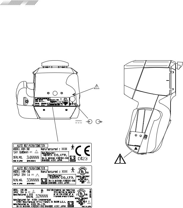
2.9 Labels
To catch the attention of the user, some labels and indications are provided on the device.
[Measuring unit]

2 - 11 


[Station]
200-240 V range
100-120 V range


 2 - 12
[Underside of battery]
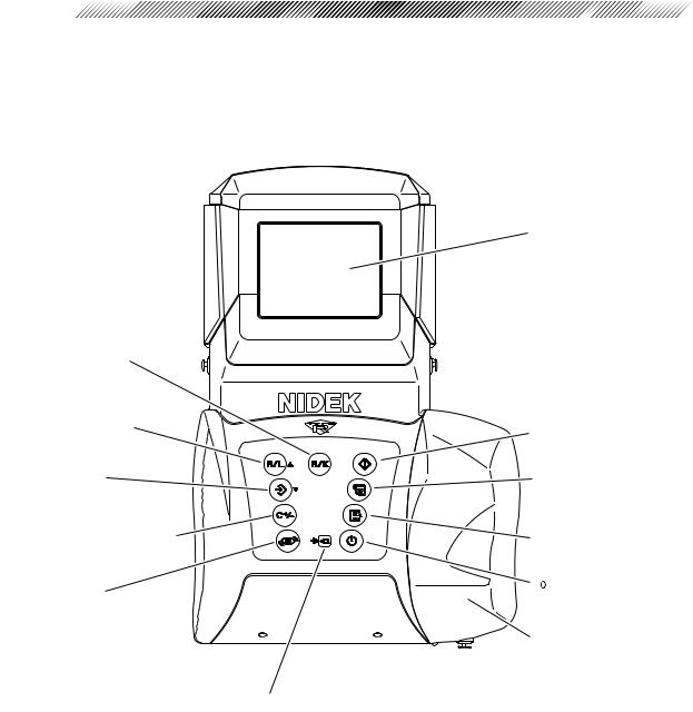
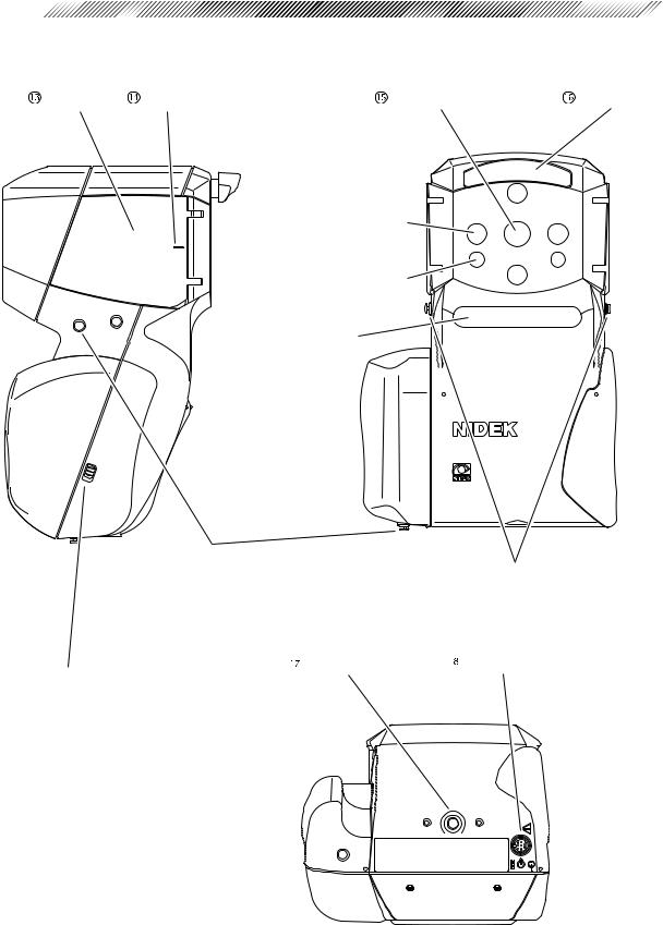
§3 CONFIGURATION
[Measuring unit]
 R/K selection button
 R/L selection button
 Memory button
 CYL mode selection button
 Angle correction button
 Charge indicator
 LCD screen
 Start button
 Print button
 Parameter setting button
 Power button
 Grip
Grip
 Angle correction button
Used to rotate the main body 90º when the patient is measured from the side.
This is used to measure a patient who is lying down.
When the parameter “41: SAGITTAL” is set to “YES”, pressing this button starts the sagittal radius measurement.
 CYL mode selection button
Establishes the CYL mode of measured results. Pressing this button changes the mode in the order of CYL – → CYL + → CYL ± → CYL – → •••.
• CYL + (Plus reading)
Cylinder data is displayed by the + reading.
• CYL – (Minus reading)
Cylinder data is displayed by the – reading.
• CYL ± (Mix reading)
In the AR measurement, cylinder data is displayed by the + reading when the refractive error is positive for any axis angle. In other cases, cylinder data is displayed by the – reading.
In the KM measurement, cylinder data is displayed by the – reading.
See page 4-7 for details of the CYL mode.
 Memory button
Stores the measured results in memory.
The memory function stores the measured results of 30 patients (60 eyes).
 R/L selection button

Sets the measuring eye. Every time the button is pressed, the indication changes in the order of  (or
(or  )→ <
)→ < >→ <
>→ < >→
>→  (or
(or  )→ •••.
If alignment is performed in the AUTO mode,
 (right-eye) or
  (left-eye) will be identified automatically.
< > (<
> (< >) indicates that the right eye (left eye) has been manually set.


 3 - 2
3 - 2
 R/K selection button
Changes the measurement mode.
The mode changes in the order of R/K mode (Serial AR & KM measurements)→ R mode (AR measurement)→ K mode (KM measurement)→ R/K mode→ •••.
 LCD screen
Displays the patient’s eye, target, focusing indicator, measured values, and measurement count, etc.
The color of the characters and the background on the LCD screen can be selected from a combination of 28 kinds.
 Start button
Places the device into the measurable state from standby.
 Print button
Prints measured results, etc.
 Parameter setting button
Used to change the settings of the device.
 Power button
Turns the measuring unit on and off. Pressing this button turns on the power and viceversa.
Turning the power on places the device into the standby mode.
The position of the chart is initialized and the chart lamp lights up.
 Grip
Grip
Used to hold the measuring unit. The battery holder is mounted inside. Open the cover to replace the battery.
 Charge indicator
Flashes while the battery in the measuring unit is being charged.
3 - 3
Eye mask |
Eye level marker |
Measuring window |
Forehead rest |
Target detector window
Focus detector window
Window for optical communications and measuring eye (R/L) detection
Hand strap mounting hooks
Hand strap is to be attached to prevent accidental drop.
 Stand screw
Lock switch
Slide this downward to remove the grip cover.
Neck strap mounting hooks
Optional neck strap is to be attached.
 Cable connector


 3 - 4
3 - 4
 Eye mask
Open this mask to shield the patient’s eye which is not measured.
This allows the patient to fixate his/her eye easier.
To avoid damage from impact, the eye mask is easily detached. To attach it, push lightly aligning the hinge part with the main body.
 Eye level marker
A guide for the patient’s eye level for measurements. It is located at both the front and back sides of the eye mask.
Adjust the measuring unit so that the center of the patient’s eye is aligned with this line.
 Measuring window
The patient looks at the chart through this window.
Keep this window clean. The measuring window checker allows automatic confirmation of cleanliness.
 Forehead rest
Place it against the patient’s forehead (top of eyebrow) to stabilize the position of the measuring unit.
The push-type lock forehead rest can be drawn out once it is pushed lightly.
Use the forehead rest so that the measuring unit will not contact the patient’s face.
 Stand screw
This screw secures the measuring unit to the portable stand (option).
 Cable connector
Connector for the cable when the measuring unit is used by deriving power from the station.
The battery can be recharged with the battery installed in the measuring unit.
Printing is possible by the connecting cable.
3 - 5
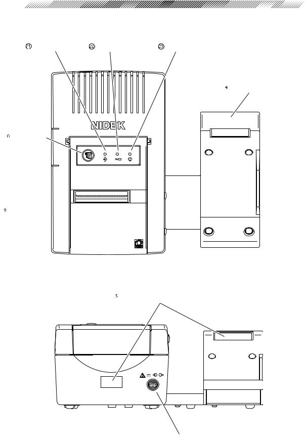
[Station]
Memory lamp |
Charge lamp |
Pilot lamp |
 Measuring unit stage
 Feed button
 Printer
 Light-receiver window for printing
 Cable connector


 3 - 6
3 - 6
 Printer
Prints measured results, etc.
 Feed button (
  )
)
Feeds the printer paper. While this button is pressed, the paper is fed.
 Memory lamp (
 )
)
Illuminates while data to be transmitted to an external computer, etc. is stored.
 Charge lamp (
 )
)
Flashes while the battery is being charged. This lamp stays illuminated after the charging is completed.
 Pilot lamp (
 )
)
Illuminates when the station is supplied with power and operating.
 Measuring unit stage
The measuring unit is put on this stage when not in use.
 Light-receiver window for printing
Receives the signal from the measuring unit during printing.
The communication distance between the measuring unit and station is within 1 meter.
 Cable connector
Connector for the cable when the measuring unit is used by deriving power from the station.

3 - 7
Data input connector |
Data output connector |
 Power connector
Power switch |
Battery slot |
 Cable hanger


 3 - 8
3 - 8
 Data input connector*
The interface cable from a lensmeter imports measured values from the NIDEK’s lensmeter.
The ARK-30 measured results are exported from the data output connector. The imported LM measured results are also exported from the data output connector.
 Data output connector*
The interface cable exports measured values to an external computer.
 Power connector
The supplied power cable is connected here. This is the combination type with a fuse holder.
Use the specified fuses.
Spare fuses are mounted in the spare fuse holders inside the printer cover of the station.
 Battery slot
The battery is inserted for recharge.
When the battery is inserted, charging will start automatically and the charge lamp (
 ) will flash.
 Cable hanger
When the cable is not in use, it is placed on this hanger.
The hanger can be easily detached since it is attached by a magnet.
*Accessory equipment connected to the analog and digital interfaces must be certified according to the appropriate national standards (for example, UL1950 for Data Processing Equipment UL 2601-1 for Medical Equipment, and CSA C22.2 No. 601-1, EN 60601-1 and IEC 60601- 1.) Furthermore, all configurations shall comply with the system standard IEC 60601-1. Anyone who connects additional equipment to the signal input part or signal output part is responsible for making sure that the system complies with the requirements of the system standard IEC 60601-1. If in doubt, consult the technical service department or your local representative.
3 - 9
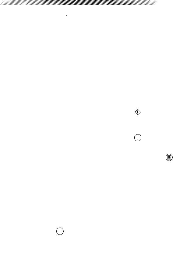
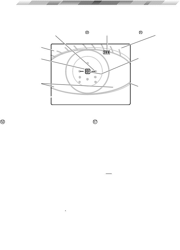
[LCD screen]
This is a sample measurement screen in the R/K mode.
 Focusing indicator
 Patient No.
 Target
 Axis correction mark

 Measurement mode
 Measured values
Battery remaining indicator |
CYL mode indication |
Corneal luminous spot Other spots around are the luminous spots of measuring light and sensor.

 Measuring eye
Measured values |
Focusing indicator |
Displays the latest measured results. The indicated items vary according to the measurement mode (R/K mode, R mode, K mode).
 Measurement mode
Indicates the selected measurement mode, R: AR measurement, K: KM measurement, R and K: R/K measurement. The figures shown on the right and left represent the number of measurements for each eye.
 AXIS correction mark
This is shown when AXIS is corrected by 90º with the angle correction button  .
.
 Target
Used to bring the patient’s eye to the center of the measuring optical axis as a guide.
 Patient No.
Displays the measured patient No. in a serial number.
The number is set in the parameter setting mode.
Indicates the distance between the measuring unit and the patient’s eye. This is a guide for focusing.
 Battery remaining indicator
Indicates the remaining charge amount of the battery installed in the measuring unit.
(

 ) indicates that the battery is getting weak and the battery needs recharging.
 CYL mode indication
Displays the established CYL mode.
 Measuring eye
Displays the right-side or left-side of the detected patient’s eye.
This can be manually set by pressing the R/L selection button  .
.
 Loading...