

Page 1

NDA-24233
ISSUE 2
STOCK # 0293886
VisuaLink 128/384
Engineering Guide
JANUARY, 1999
NEC America, Inc.
Page 2

LIABILITY DISCLAIMER
NEC America, Inc. reserves the right to change the specifications,
functions, or features, at any time, without notice.
NEC America, Inc. has pr ep ared thi s doc um ent for u se by i ts employees and custom ers. The information conta ined herein is the
property of NEC America, Inc. and shall not be reproduced without
prior written approval from NEC America, Inc.
Copyright 1999
NEC America, Inc.
Printed in USA
Page 3

EXHIBIT J1
FCC REQUIREMENTS
NEC America, Inc.
VisuaLink 128/VisuaLink 384
TYPE OF SERVICE
The VisuaLink 128 and the VisuaLink 384 are stand-alone devices that allow multimedia conferencing by
transmitting video, a udi o an d dat a t o r emote locations over the ISDN Basic Rat e in terface. The VisuaLink 128
and VisuaLink 384 connect to the ISDN digital network through separately-registered NTI equipment. They
provide POTS ports which allow a customer-provided 2500-type telephone access to the digital network.
This equipment complies with Part 68 of the FCC Rules. The equipment label will appear on the rear exterior
panel of the unit and will provide the FCC Registration Number, NEC trade name, model number, serial
number or date of manufacture and the country of origin.
TELEPHONE COMPANY PROCEDURES
The goal of the telephone company is to provide you with the best service it can. In order to do this, it may
occasionally be necessary for them to make changes in their equipment, operations, or procedures. If these
changes might affect your service or the operation of your equipment, the telephone company will give you
notice, in writing, to allow you to make any changes necessary to maintain uninterrupted service.
If you have any questi ons about your tele phone lin e, such as h ow many piece s of equip ment you can connect t o
it, the telephone company will give you notice, in writing, to allow you to make any changes necessary to
maintain uninterrupted service.
In certain circumstances, it may be necessary for the telephone company to request from you concerning the
equipment which you have connecte d to your telephone line. Upon request of the telep hone company, provide
the FCC registration numbe r and the ri nger equivalen ce number (REN) of the equi pment which i s connected to
your line; both of these items are listed on the equipment label The sum of all of the REN's on your telephone
lines should be less than five in order to assure proper service from the telephone company. In some cases, a
sum of five may not be usable on a given line.
Page 4

IF PROBLEMS ARISE
If any of your telephone equipment is not operating properly, you should immediately remove it from your
telephone lines, as it may cau se harm to the tele phone ne twork. If the telephon e company not es a prob lem, they
may temporarily discontinue service. When practical, they will notify you in advance of this disconnection. If
advance notice is not feasible, you will be notified as soon as possible. When you are notified, you will be
given the opportunity to correct the problem and informed of your right to file a complaint with the FCC.
In the event repairs are ever needed on your Visualink 128 or VisuaLink 384, they should be performed by
NEC America, Inc. or an authorized representative of NEC America, Inc. For information contact:
NEC America, Inc.
1555 W. Walnut Hill Lane
Irving, Texas 75038-3797
USA
972-751-7000
FCC REQUIREMENTS FOR CONNECTION OF TELEPHONE SYSTEMS
In order to connect this system to the telephone network, provide the telephone company with:
• the quantities and USOC numbers of the required jacks (shown below);
• the sequence in which the trunks are to be connected;
• the facility interface codes by position; and
• the ringer equivalence number or service code, as applicable, by position
MFG’s Port IDUSOC Jack
Connector
VisuaLink 128 N/A 6.0P 02IS5 1 1 AY5JPN-32617-XD-N
VisuaLink 384 N/A 6.0P 02IS5 3 1 AY5JPN-32617-XD-N
REN/Service
Code
Facility Interface
Code
# CO
Ports
# Stations Registration #
Page 5

CSA Requirement
To ensure that certified equipment is attached correctly, and only to the networks of participating carriers, the
following statement shall accompany each unit of certified equipment offered for sale. This statement must be
included conspicuously in written or electronic format, at or near the front of each copy of the operating
manual, or accompany other technical information, or be included as a separate sheet. The required statement
is:
CP-01, Issue 8, Part I
Section 14.1
NOTICE
: The Industr y Canada label identifies certified equipment. This certification means th at the
equipment meets certain telecommunications network protective, operational and safety requirements as
prescribed in the app ropri ate Terminal Equipment Technical Requirements document(s ). The Dep artment does
not guarantee the equipment will operate to the user's satisfaction.
Before installing this equipment, users should ensure that it is permissible to be connected to the facilities of
the local telecommunications company. The equipment must also be installed using an acceptable method of
connection. The customer should be aware that compliance with the above conditions may not prevent
degradation of service in some situations.
Repairs to certified equipment should be coordinated by a representative designated by the supplier. Any
repairs or alterations made by the user to this equipment, or equipment malfunctions, may give the
telecommunications company cause to request the user to disconnect the equipment.
Users should ensure for their own protection that the electrical ground connections of the power utility,
telephone lines and inte rnal metal lic water pipe s ystem, if pres ent, are conn ected togethe r. This precaution may
be particularly important in rural areas.
CAUTION:
Users should not attempt to make such connections themselves, but should contact the
appropriate electric inspection
MODEL CERTIFICATE NUMBER CERTIFICATION NUMBER
VisuaLink 128 19318 140 9004A
VisuaLink 384 19603 140 9104A
Page 6

Page 7

VisuaLink 128/384 Engineering Guide Table of Contents
Table of Contents
Chapter 1: VisuaLink Command Fundamentals ....................................................1-1
Summary ....... ........... ........... ........... ......... ........... ........... ........... ......... ........... ........... ............1-1
Communication Outline ....................................................................................................... 1-1
Physical/Ele c t ric a l ln t er fa c e .... ... ............. .. .. .............. .. ............. .. .............. .. ............. .. .......... 1-2
Communication Format ....................................................................................................... 1-3
Communication Procedure ................................................ .................................................1-5
Connecting and Incoming Call Control Basic Sequence ............................................. .......1-7
Chapter 2: Console Command List .........................................................................2-1
Chapter 3: Command Detailed Format ................................................................... 3-1
VIDEO Commands ............................................................................................................. 3-2
SVFM Setting Video Format 1-1 .................3-2
RVFM Checking Video Format Setting 1-2 .................3-2
SPIP Setting Picture-in-Picture 1-3 .................3-3
RPIP Checking Picture-in-Picture Setting 1-4 .................3-3
SSND Setting Video Input Switch 1-5 .................3-4
RSND Chec king Video Input Setting 1-6 .................3-4
SDSP Setting Monitor Output Video 1-7 .................3-5
RDSP Checking Monitor Output Video Setting 1-8 .................3-5
SPDP Setting/Checking PIP Display Format 1-9 .................3-6
SPSW Setting/Checking PIP Image when Snapshot is Viewed 1-10 ...............3-6
SCPI Setting/Checking Video Priority 1-11 ...............3-7
S263 Setting H.263 1-12 ...............3-7
R263 Checking H.263 Setting 1-13 ...............3-8
AUDIO Command ...............................................................................................................3-9
SAMD Setting Audio Mode 2-1 .................3-9
RAMD Checking Audio Mode Setting 2-2 .................3-9
SADL Setting Audio Delay 2-3 ...............3-10
RADL Checking Audio Mode Setting 2-4 ...............3-11
SMIC Setting MIC ON/OFF 2-5 ...............3-11
RMIC Checking MIC ON/OFF Setting 2-6 ...............3-12
SVOL S etting Volume 2-7 ...............3-12
RVOL Checking Volume Setting 2-8 ...............3-12
SASW Setting Audio Input/Output Port 2-9 ...............3-13
RASW Checking Audio Input/Output Port Setting 2-10 .............3-13
SMMT Sets Audio or Audio/Video Outgoing Mute Setting 2-11 .............3-14
RMMT Checking Audio or Audio/VideoOutput Mute Setting 2-12 .............3-14
SMTC Sets Audio or Audio/Video Mute Setting 2-13 .............3-15
RMTC Checking Audio or Audio/VideoOutput Mute Setti n g 2-14 .............3-15
LINE Setting Command .................................................................................................... 3-16
SNET Set ting Network Type (P x 64/56) 3-1 ........... ....3-16
RNET Checking Network Type Setting (P x 64/56) 3-2 ........... ....3-16
NNSS Setting Transmission Line Type 3-3 ........... ....3-17
NNSI Checking Transmission Line Type Setting 3-4 ...............3-17
SLSP Setting Transmission Line Speed 3-5 ........... ....3-18
RLSP Checking Transmission Line Speed Setting 3-6 ...............3-18
NDA-24233 Issue 2 Page i
Page 8

Table of Contents VisuaLink 128/384 Engineering Guide
DATA Command ............................................ .. ................................................. ................3-19
SDM2 Setting LSD Speed 4-1 ...............3-19
RDM2 Checking LSD Speed Setting 4-2 ............... 3-20
SDM3 Setting MLP Speed 4-3 ...............3-20
RDM3 Checking MLP Speed S e tt in g 4-4 .. .. ... ........ 3-21
ISDN Registering/Setting Command ................................................................................3-22
NDSS Registering My Number 5-1 ...............3-22
NDSR Checking My Number Registration 5-2 ...............3-23
MDST Registering Speed Dial 5-3 ...............3-24
MDRD Checking Speed Dial Registration 5-4 ...............3-25
NBZS Setting Incoming Call Buzzer 5-6 ............... 3-26
NBZI Checking Incoming Call Buzzer Setting 5-7 ............... 3-26
SINC Setting Incoming Call Mode 5-8 ............... 3-27
SRNG Setting/Checking Incoming Call Buzzer at Auto Answer Mode 5-9 ...............3-28
SPID Registering SPID 5-10 ............. 3-28
RPID Check ing SPID 5-11 ............. 3-29
Camera Related Registering/Setting Command ...............................................................3-30
CPPS Registering Camera Preset Position 6-1 ...............3-30
CPNS Registering Talker Name 6-2 ...............3-30
SCMK Setting Camera Model 6-3 ............... 3-31
RCMK Checking Camera Model Setting 6-4 ...............3-31
Communication Status Reading Command ................................................................. .. .. .3-32
RMAC Read Manufacturer Code 7-1 ...............3-32
RMOD Read Common Mode During Communication 7-2 ...............3-33
R221 Read H.221 Synchronous Status 7-3 ...............3-34
RPNA Read Remote Site Name (at Point-to-Point) 7-4 ...............3-34
RCST Read Participating Conference Status 7-5 ...............3-35
Alarm Related Command .................................................................................................. 3-36
CALM Read Alarm Status (1 of 2) 8-1 ...............3-36
History Reading Command ............................ .. .. .................................... .. .. .. .....................3-38
RLAM Read Communication/Alarm History 9-1 ...............3-38
Registering Local Location Name Command ........................................ .. .........................3-39
MRNS Registering Local Site Name 10-1 ............. 3-39
Serial Port Control Command ........................................................................................... 3-40
SSIO Setting Serial Port 11-1 .............3-40
RSIO Checking Serial Port Setting 11-2 ............. 3-40
Acquiring Version Command ............................................................................................3-41
RVER Requesting Software Version 12-1 ............. 3-41
Maintenance Command ................................... ................................................. .. ..............3-42
SLLB Setting Local Loopback 13-1 ............. 3-42
RLLB Checking Local Loopback Setting 13-2 ............. 3-42
Page ii NDA-24233 Issue 2
Page 9

VisuaLink 128/384 Engineering Guide Table of Contents
Report Response Control Command ......................... .. .......................... ...........................3-43
ITCS Conference Status Report Control 14-1 .............3-43
IMCU Multi-point Conference Status Report Control 14-2 .............3-43
I243 H.243 Report Control 14-3 .............3-44
ICGP Command Generator Related Report Control 14-4 .............3-44
Maintenance and Other Command ............................................. .. ....................................3-45
ISPR Setting Parameter Initialization 15-1 .............3-45
CRAM Clearing Backup Memory 15-2 .............3-45
RRST System Reset Request 15-3 .............3-45
WCLK Setting System Clock 15-4 .............3-46
RCLK Checking System Clock Setting 15-5 .............3-46
Mutli-point Conference Status Command .........................................................................3-47
RMNA Read Multi-point Conference Participating Location Name 16-1 .............3-47
RMST Read Multi-point Conference Operation Status (NEC Specific) 16-2 ........... ..3-48
RMPS Read Multi-point Conference Operation Status 16-3 .............3-49
RMMDRead Multi-point Conference Mode Status 16-4 .............3-49
Model Identification Command .........................................................................................3-50
RMES Read Model Identification 17-1 .............3-50
Audio Training Command ......................................................... ........................................3-51
ECTS Audio Training Command 18-1 .............3-51
ISDN Control Command ............. .. .......................... ................................................. .. .......3-52
NCRN Requesting Connection 19-1 .............3-52
NDSC Requesting Disconnection 19-2 .............3-53
NCIC Incoming Call Permit/Reject 19-3 .............3-53
NSTQ Communication Status Inquiry 19-4 .............3-54
Camera Control Command ...............................................................................................3-55
CAMS Request for Camera Direction Change 20-1 .............3-55
Option Control Command ................................. .......................... ......................................3-56
POCS Pointer Control 21-1 .............3-56
VCTS Talker Detection Control 21-2 .............3-56
STPR SnapShot Transmission Request 21-3 .............3-57
SXMR Standard Display Screen Setting Request 21-4 .............3-57
SXST Request to Acquire Composite Screen Setting 21-5 .............3-58
Multi-point Conference Control ......................................................................................... 3-59
COPR Request to Chairman Control 22-1 .............3-59
CSPR Multiple Address Transmission Request 22-2 .............3-60
CRPR Specific Picture Reception Request 22-3 .............3-61
CMPR Request to Switch Multiple Address Originator Monitor 22-4 .............3-61
Opening Control Command ..................... .. .. ...................................... .. .. ...........................3-62
OMES Opening Message at Unit Activation 24-1 .............3-62
Communication Status Report Command ........................................... .. ...........................3-63
H221 H.221 Synchronous Status Report 25-1 .............3-63
IMAC Manufacturer Code Report 25-2 .............3-63
IMOD Report of Common Mode in Communication 25-3 .............3-64
NDA-24233 Issue 2 Page iii
Page 10

Table of Contents VisuaLink 128/384 Engineering Guide
Alarm Status Report Command ........................................................................................3-65
RALM Alarm Status Change Report (1 of 2) 26-1 ............. 3-65
RALM Alarm Status Change Report (2 of 2) 26-1 ............. 3-66
Video Status Report Command ......................................... .. .. .. ...................................... .. .3-67
RVSR Incoming Video Synchronous Status Report 27-1 ............. 3-67
Participating Status Report Command ........... .......................... .........................................3-68
ICST Participating Conference Status Report 28-1 .............3-68
ISDN Report Command ...................................................................................... .. ............3-69
NALT Display During Calling 29-1 .............3-69
NINC Incoming Call Report 29-2 ............. 3-69
NONL On-line Report 29-3 ............. 3-69
NDCI Disconnection Report 29-4 ............. 3-70
Camera Control Report Command ...................................................................................3-71
CAMI Camera Status Report 30-1 ............. 3-71
CPNI Talker Name Display Report 30-2 .............3-71
Option Control Report Command .....................................................................................3-72
STEI SnapShot Transmission Ending Report 31-1 ............. 3-72
RFVR SnapShot Reception Report 31-2 ............. 3-72
Other Report Command .................................................................. ..................................3-73
CGSI Automatic Activation File Starting Report 32-1 ............. 3-73
CGEI Automatic Activating File Ending Report 32-2 ............. 3-73
Multi-Point Related Report Command ....................................... .. .. .. .. ..............................3-74
IMPS Multi-point Conference Operation Status Report 33-1 .............3-74
IMMD Multi-point Conference Mode Status Report 33-2 .............3-74
COPI Acquisition of Right to Operate Report 33-3 .............3-74
CSPI Multiple Address Transmission Report 33-4 ............. 3-75
CRPI Specific Picture Reception Report 33-5 .............3-75
CVCI Talker Detection Control Report 33-6 .............3-75
CSSC SnapShot Transmission Permit Report 33-7 ............. 3-76
CMPI Multiple Address Originator Monitor Video Switch Report 33-8 .............3-76
CJNI Terminal Connection Report 33-9 .............3-76
CSTI Conference Status Report 33-10 ........... 3-77
Multi-Screen Related Report Command ...................................................... .....................3-78
XMII Composite Screen Setting Report 34-1 .............3-78
XMCI Standard Display Screen Setting Report 34-2 .............3-78
XSCI Response to Composite Screen Setting Request 34-3 ............. 3-79
Microphone Command ......................................................................................................3-80
PPNI Voice Activate Microphone Report 35-1 ............. 3-80
System Error Command ............................................. ................................................. .. ...3-81
ERRI System Error Report 36-1 .............3-81
On-Screen Command .......................................................................................................3-82
SOSD Setting On-Screen Display 37-1 .............3-82
Current Power OFF Condition ................................................................. .. .......................3-83
CSTB Current Power OFF Condition 38-1 .............3-83
Page iv NDA-24233 Issue 2
Page 11

VisuaLink 128/384 Engineering Guide Table of Contents
Chapter 4: Error Response Table ............................................................................ 4-1
Chapter 5: List of Factors for Disconnection in Table ..........................................5-1
Appendix A: Pin-out Specification...........................................................................A-1
Appendix B: Line Speed Specifications..................................................................B-1
Appendix C: ISDN Q.931 Cause Code Definitions..................................................C-1
NDA-24233 Issue 2 Page v
Page 12

VisuaLink 128/384 Engineering Guide List of Tables
List of Tables
Table 1: VIDEO Command .................................................................................................... 2-1
Table 2: AUDIO Command ....................................................................................................2-1
Table 3: LINE Setting Command ........................................................................................... 2-1
Table 4: DATA Command ...................................................................................................... 2-2
Table 5: ISDN Registering/Setting Command........................................................................ 2-2
Table 6: Camera related Registering/Setting Command ......................................................... 2-2
Table 7: Communication Status Reading Command .............................................................. 2-2
Table 8: Alarm related Command ........................................................................................... 2-2
Table 9: History Reading Command ...................................................................................... 2-2
Table 10: Registering Local Location Name Command .......................................................... 2-3
Table 11: Serial Port Control Command ................................................................................... 2-3
Table 12: Acquiring Version Command ................................................................................... 2-3
Table 13: Maintenance Command ............................................................................................ 2-3
Table 14: Report Response Control Command ........................................................................2-3
Table 15: Maintenance and Other Command ...........................................................................2-3
Table 16: Maintenance and Other Command ...........................................................................2-3
Table 17: Model Identification Command ................................................................................ 2-4
Table 18: Audio Training Command ........................................................................................2-4
Table 19: ISDN Control Command .......................................................................................... 2-4
Table 20: Camera Control Command ....................................................................................... 2-4
Table 21: Option Control Command ........................................................................................ 2-4
Table 22: Multi-point Conference Control .............................................................................. 2-4
Table 23: Opening Message Command ....................................................................................2-4
Table 24: Communication Status Report Command ................................................................ 2-5
Table 25: Alarm Status Report Command ................................................................................ 2-5
Table 26: Video Status Report Command ................................................................................2-5
Table 27: Participating Status Report Command ...................................................................... 2-5
Table 28: ISDN - Report Command ......................................................................................... 2-5
Table 29: Camera Control Report Command ........................................................................... 2-5
Table 30: Option Control Report Command ............................................................................. 2-5
Table 31: Other Report Command ............................................................................................ 2-5
Table 32: Multi-point Related Report Command ..................................................................... 2-6
Table 33: Multi-Screen Related Report Command ................................................................... 2-6
Table 34: Microphone Command ............................................................................................. 2-6
Table 35: System Error Command ............................................................................................ 2-6
Table 36: On-Screen Display ....................................................................................................2-6
Table 37: Current Power OFF Condition .................................................................................. 2-6
Table 4-1: Error Response Table ...............................................................................................4-1
NDA-24233 Issue 2 Page vi
Page 13

VisuaLink 128/384 Engineering Guide Chapter 1
Chapter 1: VisuaLink Comm a n d Fu nd a m en ta l s
Preface
Thank you very much for purchasing the VisuaLink 128 or VisuaLink 384.
VisuaLink is suitable for a conference with one to three people on a site, and it is a device to realize a
multimedia communication of video, voice, and graphic information by connecting to an ISDN line.
This document explains the external console of the VisuaLink from a console such as a personal computer.
NEC Corporation
Notes to Remember:
(1) It is prohibited to copy a part of or the whole of the con tents of this document without permission.
(2) The contents of this document may be modified without notice.
(3) We did our best in creation of this document; however, if you notice any problems, errors, and
omissions, please let us know.
(4) We are not responsible for the result of any operation of the device regardless of the above note.
(5) Please prepare cou ntermea sures such as recover y and ba ckup for pos sible fa ilures on a syste m side
when you use this device in a system in which a superior reliability is expected.
1.1 Summary
VisuaLink is equipped with a serial external control port that enables a control from a console such as a
personal computer.
The V isuaLi nk execute s a command a nd retur ns a res ponse base d on the i nputting of a command that co nsist of
4 characters or one character and three numbers.
1.2 Communication Outline
Communication protocol between the VisuaLink and a console are consisted of the following:
[1] Command: A protocol issued by a console executes a process on VisuaLink.
[2] Response: A protocol that issues a result for a command to a console. It is always issued at a command
reception. Responses are normal ending response and error response.
[3] Report: When a status is changed inside VisuaLink, a change notice such as an alarm is issued to a
console. Message protocol is issued independently from a command.
NDA-24233 Issue 2 Page 1-1
Page 14

Chapter 1 VisuaLink 128/384 Engineering Guide
1.3 Physica l/Electrical lnterface
The external control port is at the back of the VisuaLink and uses DIN8 pin connectors. The maximum length
of the control cable shall be no more than 20 ft. (6.1 meter) due to electric characteristics. Connector pin
positions are as follows:
NO Name Direction Features
1 RS OUT Request to Send
2CS IN Clear to Send
3 SD OUT Send Data
4 GND - Signal Ground
5 RD IN Receive Data
6
7 DTK OUT Data Terminal Ready
8 DSR IN Data Set Ready
Note:
Directions of signals are output from VisuaLink.
Page 1-2 NDA-24233 Issue 2
Page 15
VisuaLink 128/384 Engineering Guide Chapter 1
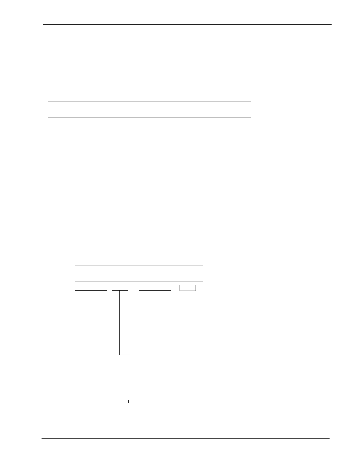
1.4 Communication Format
Communication between a console and VisuaLink 128/384 is done in a start-stop synchronization of the
following fo rmat.
Data Format
START
123456789
Data Length: 7, 8 bit ASCII code
Stop Bit: 1 bit
Parity: Even, Odd, NONE parity
Baud: 1200, 2400, 4800, 9600bps
Note:
Default setting for VisuaLink is 9600, 8, none, 1.
To change the default setting use the SSPR command.
A: Connect termin al to VisuaLink Serial 2
B: Set terminal application to:
Baud: 9600
Parity: Even
Bit: 8
Stopbit: 1
C: Calculate the Baud, Parity, and Bit
b7 b6 b5 b4 b3 b2 b1 b
PTY
0
STOPAS CII 8bit
Not in use
Not in use
00 : 1200bps
01 : 2400bps
10 : 4800bps
11 : 9600bps
00 : 7 bit | EVEN | STOP
01 1 7 bit |ODD | STOP
10 : 8 bit | EVEN | STOP
11 : 8 bit | NONE | STOP
D: Set system parameter command for the appropriate setting
Example: SSPR 168=21
Means: Your VL in now set up for 2400, 8, EVEN, 1
E: Reset the VL.
NDA-24233 Issue 2 Page 1-3
Page 16

Chapter 1 VisuaLink 128/384 Engineering Guide
Command Format
Command Name
Space Parameter CR+LF
Command: Transmit 4-character commands (only upper case can be used)
Space: More than one space is transmitted between a command and a parameter
Parameter: If a command requires a parameter, a parameter is assigned. (Only upper case can be used)
However, if parameters are more than one, more than one space is transmitted between parameters.
CR: Transmit
LF: Transmit
Carriage Return Code
Line Field
(OAH)
(ODH).
Response F ormat
When the VisuaLink 128/384 is provisioned and controlled wit h a cons ol e, VisuaLink 128/384 always sends a
response. Responses are normal response and error response. When sending a command from a console,
please transmit the next command after checking a response. A response is transmitted in the following
format.
Normal Ending
Response Parameter (when required)
OK
CR+LF
Parameter: If a command is inquiring a provisioned value, a response parameter is returned. If there is no.
parameter, it is omit ted. However, if parameters are more than one, more than one s pace is
transmitted between parameters.
Space: More than one space is transmitted between a command and a parameter.
CR: Transmit
LF: Transmit
Carriage Rerun Code
Line Field
(OAH)
(ODH).
Error Ending
ERRxx CR+LF
ERRxx: Three-character
CR: Transmit
LF: Transmit
ERR
and a 2-digit error number are transmitted indicating a failure.
Carriage Return Code
Line Field
(OAH)
(ODH).
Report Format
Command Name
Space Parameter CR+LF
Command: Transmit 4-character reports Command (only upper case can be used)
Space: More than one space is transmitted between a command and a parameter
Parameter: If a command requires a parameter, a parameter is assigned. (Only upper case can be used)
However, if parameters are more than one, more than one space is transmitted between parameters.
CR: Transmit
LF: Transmit
Page 1-4 NDA-24233 Issue 2
Carriage Return Code
Line Field
(OAH)
(ODH).
Page 17

VisuaLink 128/384 Engineering Guide Chapter 1
1.5 Communication Procedure
There is no procedure for communication between a console and VisuaLink as a rule. Therefore, a
communication line is pr esumed to be error-free. When it is remotely operat ed with a mode m, efficient
operation may not be expected when a line error occurs. Because of this, in a remote control, a modem with
error correction feature shall be used, or VisuaLink shall be checked for operation.
Command/Response Procedure
VisuaLink transmits a confirmation on whether a command is received and the process is completed. After
sending a command, please always analyze the transmitted response before issuing a next command. If the
next command is issued before a response, an error response such as ''currently processing'' may be returned.
PC Console VisuaLink
Command 1
Response
Command 2
Response
(1) Command 1 is issued using the external control port rather than a personal computer.
(2) Analysis of a received command (parameter error, etc.) is implemented.
(3) After an analysis, if it is normal, a normal response is transmitted to a personal computer after
transmitting to the remote in communication. However, if it is error response, the error shall be
analyzed, and a command shall be either suspended or re-issued.
(4) After verifying that Response 1 is normal, issue Command 2.
Note:
After issuing a command from a console, if an alarm emits in VisuaLink, an alarm report may be
transmitted before a response to the command.
Abnormal Handshake Procedure
When the VisuaLink receives a report command from a remote unit at a time the VisuaLink is sending a
command to the remote unit in communication, the VisuaLink transmits an indication to a PC using the
external control port and then transmits a command to the remote unit.
Console VisuaLink Remote
Command 1
Report
Report Command
Response 1
NDA-24233 Issue 2 Page 1-5
Command 1
Page 18

Chapter 1 VisuaLink 128/384 Engineering Guide
(1) Command 1 is issued using the external control port rather than a personal computer.
(2) If a report is received from the remote unit before a transmission of Command 1, it transmits a report to
a PC and then transmits C ommand 1 to th e remote unit. It transmits R esponse 1 to the PC after t he
transmission. However, in parameter error and etc., it immediately transmits an error response. When an
error response is received, it analyzes the error contents and sus pends the command issuance or reissues
a command.
Page 1-6 NDA-24233 Issue 2
Page 19
VisuaLink 128/384 Engineering Guide Chapter 1
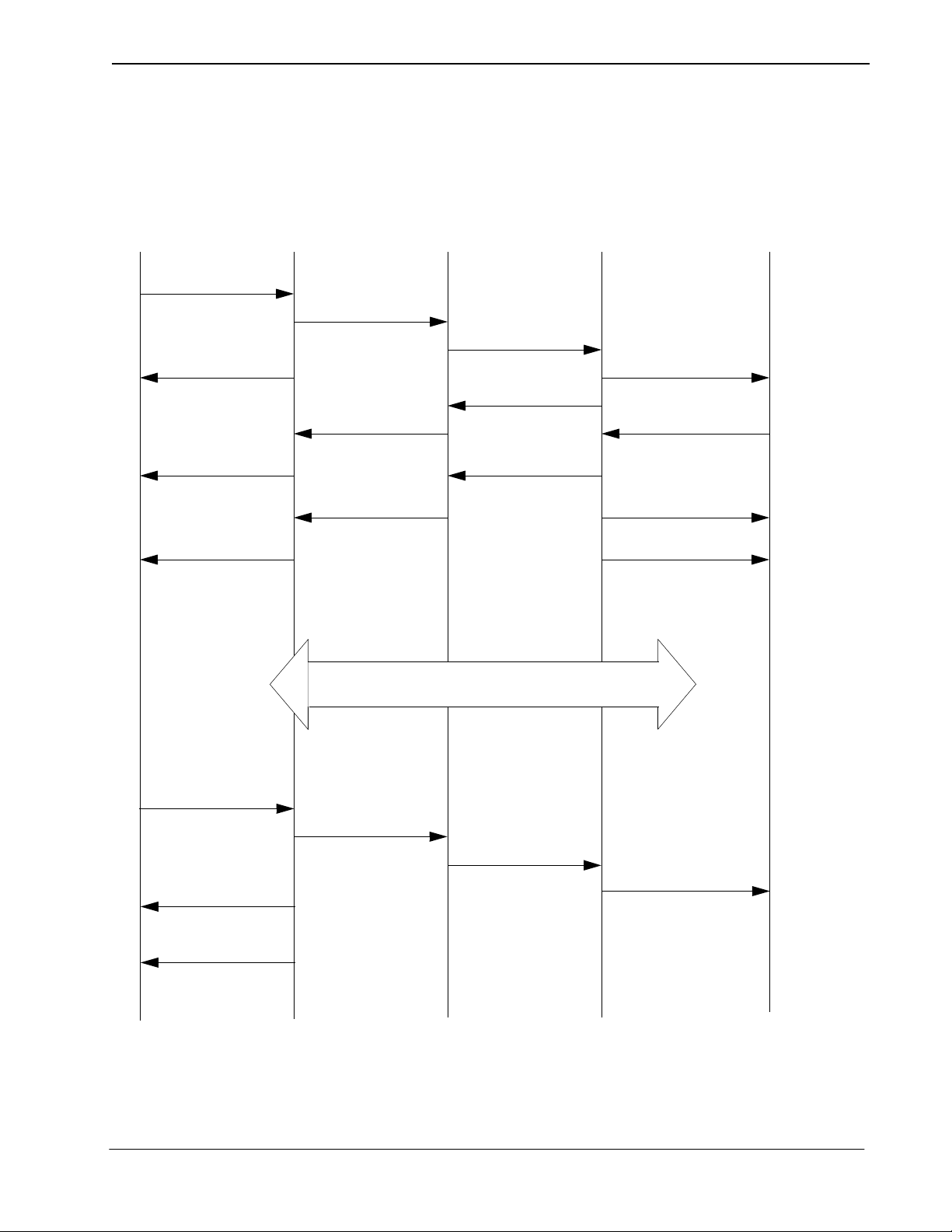
1.6 Connecting and Incoming Call Control Basic Sequence
Connecting and incoming call control basic sequence (when the incoming call mode of the VisuaLink
receiving a call is set to the manual incoming call setting) is shown in the following.
Console
NCRN
OK
NALT
NONL
VisuaLink
Call Origination
Connecting
Connection
ISDN
Incoming Call
Connecting
Connection
VisuaLink Console
NINC
NCIC
OK
NONL
Note 1:
Note 2:
Communicating
NDSC
Disconnect
Disconnect
NDCI
OK
NDCI
Detailed sequence in a network is omitted in this description.
Parameters of each command is omitted in this description.
NDA-24233 Issue 2 Page 1-7
Page 20

Chapter 1 VisuaLink 128/384 Engineering Guide
This page is for your notes.
Page 1-8 NDA-24233 Issue 2
Page 21

VisuaLink 128/384 Engineering Guide Chapter 2
Chapter 2: Console Command List
Table 1: VIDEO Command
NO Featu r e Command Name Process
1-1 Setting Video Format SVFM Setting
1-2 Checking Video Format S etting RVFM Status
1-3 Setting Picture-in-Picture SPIP Setting
1-4 Checking Picture-in-Picture Setting RPIP Status
1-5 Setting Video Input Switch SNDS Setting
1-6 Checking Video Input Setting RSND Status
1-7 Setting Monitor Output Video SDSP Setting
1-8 Checking Monitor Output Video Setting RDSP Status
1-9 Setting /Checking PIP Display Format SPDP Setting/Stat us
1-10 Setting/Checking PIP During Snapshot SPSW Setting/Status
1-11 Setting/Checking Video Priority SCPI Setting/Status
1-12 Setting H.263 S263 Setting
1-13 Checking H263 Setting R263 Setting
Table 2: AUDIO Command
NO Featu r e Command Name Process
2-1 Setting Audio Mode SAMD Setting
2-2 Checking Audio Mode Setting RAMD Status
2-3 Setting Audio Delay SADL Setting
2-4 Checking Audio Delay Setting RADL Status
2-5 Setting MIC On/Off SMIC Setting
2-6 Checking MIC On/Off Setting RMIC Status
2-7 Setting Volume SVOL Setting
2-8 Checking Volume Setting RVOL Status
2-9 Setting Audio Input/Output Port SASW Setting
2-10 Checking Audio Input/Output Port Setting RASW Status
2-11
2-12
2-13
2-14
Setting Audio Mute Operation at start of
Communications
Reads the current Mute mode setting at start of
Communications
Sets the Audio and Audio/Video Mute mode at start
of Communications
Reads the current Mute control at start of
Communications
SMMT Setting
RMMT Status
SMTC Setting
RMTC Status
Table 3: LINE Setting Command
NO Featu r e Command Name Process
3-1 Setting Network Type (P x 64/56) SNET Setting
3-2 Checking Ne twork Type Setting (P x 64/56) RNET Status
3-3 Setting Transmission Line Type NNS S Setting
3-4 Checking Transmission Line Type Setting NNSI Status
3-5 Setting Transmission Line Speed SLSP Setting
3-6 Checking Transmission Line Speed Setting RLSP Status
NDA-24233 Issue 2 Page 2-1
Page 22

Chapter 2 VisuaLink 128/384 Engineering Guide
Table 4: DATA Command
NO Featu r e Command Name Process
4-1 Setting LSD Speed SAM2 Setting
4-2 Checking LSD Speed Setting RAM2 Status
4-3 Setting MLP Speed SDM3 Setting
4-4 Checking MLP Speed Setting RDM3 Status
Table 5: ISDN Registering/Setting Command
NO Featu r e Command Name Process
5-1 Registering My Number NDSS Setting
5-2 Checking My Number Registration NDSR Status
5-3 Registering Speed Dial MDST Setting
5-4 Checking Speed Dial Registration MDRD Status
5-6 Setting Incoming Call Buzzer NBZS Setting
5-7 Checking Incoming Call Buzzer Setting NBZI Status
5-8 Setting Incoming Call Mode SINC Setting/Status
5-9
5-10 Registering SPID SPID Setting
5-11 Checking SPID RPID Status
Setting/Checking Incoming Call Buzzer at Auto
Answer Mode
SRNG Setting/Status
Table 6: Camera related Registering/Setting Command
NO Featu r e Command Name Process
6-1 Registering Camera Preset Position CPPS Setting
6-2 Registering Talker Name CPNS Setting
6-3 Setting Camera Model SCMK Setting
6-4 Checking Camera Model Setting RCMK Status
Table 7: Communication Status Reading Command
NO Featu r e Command Name Process
7-1 Read Manufacturer Code RMAC Status
7-2 Read Common Mode During Communication RMOD Status
7-3 Read H.221 Synchronous Status R221 Status
7-4 Read Remote Site Name (at Point-to-Point) RPNA Status
7-5 Read Pa rticipating Conference Status RCST Status
Table 8: Alarm related Command
NO Featu r e Command Name Process
8-1 Read Alarm Status CALM Status
Table 9: History Reading Command
NO Featu r e Command Name Process
9-1 Read Communication/Alarm History RLAM Status
Page 2-2 NDA-24233 Issue 2
Page 23

VisuaLink 128/384 Engineering Guide Chapter 2
Table 10: Registering Local Location Name Command
NO Featu r e Command Name Process
10-1 Registering Local Site Name MRNS Setting
Table 11: Serial Port Control Command
NO Featu r e Command Name Process
11-1 Setting Serial Port SSIO Setting
11-2 Checking Serial Port Set ting RSIO Status
Table 12: Acquiring Version Command
NO Featu r e Command Name Process
12-1 Requesting Software Version RVER Operation
Table 13: Maintenance Command
NO Featu r e Command Name Process
13-1 Setting Local Loopback SLLB Operation
13-2 Checking Local Loopback Setting RLLB Status
Table 14: Report Response Control Command
NO Featu r e Command Name Process
14-1 Conference Status Report Control ITCS Operation
14-2 Multi-point Conference Status Report Control IMCU Operation
14-3 H.243 Report Control I2 43 Operation
14-4 Command Generator Related Report Control ICGP Operation
Table 15: Maintenance and Other Command
NO Featu r e Command Name Process
15-1 Setting Parameter Initialization ISPR Operation
15-2 Clearing Backup Memory CRAM Operation
15-3 System Reset Request RRST Operation
15-4 Setting System Clock WCLK Setting
15-5 Checking System Clock Setting RCLK Status
Table 16: Maintenance and Other Command
NO Featu r e Command Name Process
16-1
16-2
16-3 Read Multi-point Confere nce Operatio n Status RMPS Status
16-4 Read Multi-point Confere nce Mode Status RMMD Statu s
Read Multi-point Conference Participating Location
Name
Read Multi-point Conf e rence Oper ation St atus (NEC
Specific)
RMNA Status
RMST Status
NDA-24233 Issue 2 Page 2-3
Page 24

Chapter 2 VisuaLink 128/384 Engineering Guide
Table 17: Model Identification Command
NO Featu r e Command Name Process
17-1 Read Model Identification RMES Status
Table 18: Audio Training Command
NO Featu r e Command Name Process
18-1 Initiate Audio Training ECTS Operation
Table 19: ISDN Control Command
NO Featu r e Command Name Process
19-1 Requesting Connection NCRN Operation
19-2 Request Disconnection NDSC Operation
19-3 Incoming Call Permit/Reject NCIC Operation
19-4 Communication Status Inquiry NSTQ Operation
Table 20: Camera Control Command
NO Featu r e Command Name Process
20-1 Request for Camera Direction Change CAMS Operation
Table 21: Option Control Command
NO Featu r e Command Name Process
21-1 Pointer Control POCS Operation
21-2 Talker Detection Control VCTS Operation
21-3 SnapShot Transmission Request STPR Operation
21-4 Standard Display Screen Setting Request SXMR Operation
21-5 Request to Acquire Composite Screen Setting SXST Operation
Table 22: Multi-point Conference Control
NO Featu r e Command Name Process
22-1 Request to Chair m an Control COPR Operation
22-2 Multiple Address Transmission Request CSPR Operation
22-3 Specific Picture Reception Request CRPR Operation
22-4
Request to Switch Multiple Address Origi nator
Monitor
CMPR Operation
Table 23: Opening Message Command
NO Featu r e Command Name Process
23-1 Opening Message at Unit Activation OMES Report
Page 2-4 NDA-24233 Issue 2
Page 25

VisuaLink 128/384 Engineering Guide Chapter 2
Table 24: Communication Status Report Command
NO Featu r e Command Name Process
24-1 H.221 Synchro no us Statu s Report H221 Report
24-2 Manufacturer Code Report IMAC Report
24-3 Report of Common Mode in Communication IMOD Report
Table 25: Alarm Status Report Command
NO Featu r e Command Name Process
25-1 Alarm Status Change Report RALM Report
Table 26: Video Status Report Command
NO Featu r e Command Name Process
26-1 Incoming Video Synchronous Status Report RVSR Report
Table 27: Participating Status Report Command
NO Featu r e Command Name Process
27-1 Participating Conference Status Report ICST Report
Table 28: ISDN - Report Command
NO Featu r e Command Name Process
28-1 Display During Calling NALT Report
28-2 Incoming Call Report NINC Report
28-3 On-line Report NONL Report
28-4 Disconnection Report NDCI Report
Table 29: Camera Control Report Command
NO Featu r e Command Name Process
29-1 Camera Status Report CAMI Report
29-2 Talker Name Display Report CPNI Report
Table 30: Option Control Report Command
NO Featu r e Command Name Process
30-1 SnapShot Transmission Ending Report STEI Report
30-2 SnapShot Reception Report RFVR Report
Table 31: Other Report Command
NO Featu r e Command Name Process
31-1 Automatic Activating File Starting Report CGSI Report
31-2 Automatic Activating File Ending Report CGEI Report
NDA-24233 Issue 2 Page 2-5
Page 26

Chapter 2 VisuaLink 128/384 Engineering Guide
Table 32: Multi-point Related Report Command
NO Featu r e Command Name Process
32-1 Multi-point Conference Operation Status Report IMPS Report
32-2 Multi-point Conference M ode Status Report IMMD Report
32-3 Acquisition of Right to Operate Report COPI Report
32-4 Multiple Address Transmission Report CSPI Report
32-5 Specific Picture Reception Report CRPI Report
32-6 Talker Detection Control Report CVCI Report
32-7 SnapShot Transmission Permit Report CSSC Report
32-8
32-9 Terminal Con nection Repor t CJNI Report
32-10 Conference Status Report CSTI Report
Multiple Address Originator Monitor Video Switch
Report
CMPI Report
Table 33: Multi-Screen Related Report Command
NO Featu r e Command Name Process
33-1 Composite Screen Setting Report XMI I Report
33-2 Standard Display Screen Setting Report XMCI Report
33-3 Response to Composite Screen Setting Request XSCI Report
Table 34: Microphone Command
NO Featu r e Command Name Process
34-1 Voice Activate Microphone Report PPNI Report
Table 35: System Error Command
NO Featu r e Command Name Process
35-1 System Error Report ERRI Report
Table 36: On-Screen Display
36-1 Setting On-Screen Display SOSD Operation
Table 37: Current Power OFF Condition
37-1 Set and read the current Power Off Condition CSTB Status/Report
Page 2-6 NDA-24233 Issue 2
Page 27

VisuaLink 128/384 Engineering Guide Console Command List
Chapter 3: Command Detailed Format
Command details are described in this section according to the following format.
Command Name Command Number
Description:
Command Format:
Response:
Describe command features.
Describe command input format.
Describe a response to a command.
NDA-24233 Issue 2 Page 3-1
Page 28

Console Command List VisuaLink 128/384 Engineering Guide
3.1 VIDEO Commands
SVFM Setting Video Format 1-1
Description:
Command Format: SVFM p1
Response: Normal Response:OK
This sets video format. VisuaLink 128/384 is equipped with a feature to
code active video with kind s of resolution. The f ormats are QCIF and CIF
(FICF in parameter) based on the ITU-T Recommendation H.261 and
H.263. Resolution setting affects transmitted video. Received video
format follows a specification from the transmitting side. If FCIF is
specified in the remote unit, it automatically receives with FCIF
resolution.
p1: QCIF: QCIF
FCIF: FCIF
Error Response: ERR01
ERR07
ERR14
ERR21
ERR87
RVFM Checking Video Format Setting 1-2
Description:
Command Format: RVFM
Response: Normal Response: p1 OK
Page 3-2 NDA-24233 Issue 2
Checks the current video format setting.
p1: QCIF: QCIF
FCIF: FCIF
Error Response: ERR01
ERR07
ERR87
Page 29

VisuaLink 128/384 Engineering Guide Console Command List
SPIP Setting Picture-in-Picture 1-3
Description:
Command Format:
Response: Normal Response: OK
Sets PIP (small screen) display
SPIP p1 p2
p1: ON : PIP output ON
OFF : PIP output OFF
P2: RT : Display at top right
RB : Display at bottom right
LT : Display at top left
LB : Display at bottom left
Note:
p2 is omitted when p1 = Off
Error Response: ERR01
ERR07
ERR85
ERR87
RPIP Checking Picture-in-Picture Setting 1-4
Description:
Command Format: RPIP
Response:
Checks the current PIP display status
Normal Response: p1 p2 OK
Error Response: ERR01
p1: ON : PIP output ON
OFF : PIP output OFF
p2: RT : Display at top right
RB : Display at bottom right
LT : Display at top left
LB : Display at bottom left
ERR01
ERR87
NDA-24233 Issue 2 Page 3-3
Page 30

Console Command List VisuaLink 128/384 Engineering Guide
SSND Setting Video Input Switch 1-5
Description: This sets video input switch.
Command Format:
Response:
SSND p1 p2
p1: L : local site
R : remote site
p2: C1 : Camera 1
C2 : Camera 2
Normal Response: OK
Error Response: ERR01
ERR07
ERR20
ERR85
ERR87
RSND Checking Video Input Setting 1-6
Description:
Checks the current video input sending status.
Command Format:
Response:
RSND p1
p1: L: local site
R: remote site
Normal Response: p1 OK
p1: C1: Camera 1
C2: Camera 2
Error Response: ERR01
ERR07
ERR20
ERR87
Page 3-4 NDA-24233 Issue 2
Page 31

VisuaLink 128/384 Engineering Guide Console Command List
SDSP Setting Monitor Output Video 1-7
Description:
Command Format:
Response:
Note:
User will be unable to switch to STILL PICTURE if STILL PICTURE graphics has not been sent.
Sets output video image.
SDSP p1
p1: TX : Transmission Video
RX : Reception Video
STL : Still-picture
Normal Response: OK
Error Response: ERR01
ERR07
ERR85
ERR87
RDSP Checking Monitor Output Video Setting 1-8
Description:
Checks the current video output setting
Command Format: RDSP
Response:
Normal Response: p1 OK
Error Response: ERR01
p1: TX : Transmission Video
RX : Reception Video
STL : Still-picture
ERR07
ERR87
NDA-24233 Issue 2 Page 3-5
Page 32

Console Command List VisuaLink 128/384 Engineering Guide
SPDP Setting/Checking PIP Display Format 1-9
Description:
Command Format:
Response:
Setting the display image seen in the picture-in-picture (PIP) window.
SPDP [p1]
p1: M : mirror image is displayed
N : non-mirror image is displayed
Note:
When p1 is omitted, the cu rrent setting is reported.
Normal Response:
If p1 is set: OK
If p1 is omi tted:
p1 OK
p1: M : mirror display
N : non-mirror display
Error Response: ERR01
SPSW Setting/Checking PIP Image when Snapshot is Viewed 1-10
Description:
Command Format:
Response:
Setting the display image seen in the picture-in-picture (PIP) window
when a snapshot is viewed.
SPSW [p1]
p1: 1 : Receiving video
3 : Transmitting video
Note:
When p1 is omitted, the cu rrent setting is reported.
Normal Response:
If p1 is set: OK
If p1 is omi tted:
p1 OK
p1: 1 : Receiving video
3 : Transmitting video
Error Response: ERR01
Page 3-6 NDA-24233 Issue 2
Page 33

VisuaLink 128/384 Engineering Guide Console Command List
SCPI Setting/Checking Video Priority 1-11
Description: The V isuaL ink has a function to automat ically optimize the pi cture quality ,
(e.g., number of frames, resolution, coding, noise, etc.). In low bit rate
coding there is characteristic for r esolution and frame to op pose each other .
If resolution is imposed, the number of frames (motion) bec om es les s. If
however the number of frames increases, resolution quality is degraded.
This requires a trade off.
Command Format:
SCPI [p1]
p1: R : Resolution
M: Motion
Note:
When p1 is omitted, th e current se tting is repo rted.
Response:
Normal Response:
If p1 is set: OK
If p1 is omi tted:
p1 OK
p1: R : Resolution
M: Motion
Error Response: ERR01
S263 Setting H.263 1-12
Description:
Command Format:
Setting video coding mode to ITU-T Recommendation H.263
S263 p1
p1: ON : H.263 available
OFF : H.263 not available
Response:
NDA-24233 Issue 2 Page 3-7
Normal Response: OK
Error Response: ERR01
Page 34

Console Command List VisuaLink 128/384 Engineering Guide
R263 Checking H.263 Setting 1-13
Description:
Command Format:
Response:
Reporting the current setting by S263 command
R263
Normal Response: p1 OK
p1: ON : H.263 available
OFF : H.263 not available
Error Response: ERR01
ERR07
ERR14
ERR21
ERR87
Page 3-8 NDA-24233 Issue 2
Page 35

VisuaLink 128/384 Engineering Guide Console Command List
3.2 AUDIO Command
SAMD Setting Audio Mode 2-1
Description: Sets the audio coding format. The VisuaLink is capable of µ-Law PCM,
SBADPCM and LP-CELP.
Command Format: SAMD p1
p1: OFF : OFF
ULW : G711 (µ-Law PCM) (56 kbps)
SBA : G722 (SB-ADPCM) (48 kbps, 56 kbps)
LDC : G728 (LD-CELP) (16 kbps)
Response: Normal Response: OK
Error Response: ERR01
ERR07
ERR14
ERR21
ERR87
RAMD Checking Audio Mode Setting 2-2
Description: Check current audio mode setting
Command Format: RAMD
Response: Normal Response: p1 OK
p1: OFF : OFF
ULW : G711 (µ-Law PCM) (56 kbps)
SBA : G722 (SB-ADPCM) (48 kbps, 56 kbps)
LDC : G728 (LD-CELP) (16 kbps)
Error Response: ERR01
ERR07
ERR87
NDA-24233 Issue 2 Page 3-9
Page 36

Console Command List VisuaLink 128/384 Engineering Guide
SADL Setting Audio Delay 2-3
Description: Sets audio delay (lip sink). Delay is generated when video is coded in
transmission, and the amount of delay differs dependi ng on a transmission
speed. On the contrary, audio coding delay is about 1/1000 ~ 1/100, so a
problem that a per son ’s lips and audio cannot be s ynchronized (lip si nk) .
VisuaLink is equipped with a feature to insert a delay in audio to
compensate lip sink by adjusting a mount of delay.
Command Format: SADL p1 p2 p3
p1: 64 : 56/64 kpbs
2x64 : 2x56/2x64 kbps
3B : 168/192 kbps
4B : 224/256 kbps
5B : 280/320 kbps
6B : 336/384 kbps
p2: 000-024 : 3-digit in decimal fixed (10msec step)
p3: TX : Transmission side
Response: Normal Response: OK
Error Response: ERR01
ERR05
ERR49
ERR87
Note:
If VL128, setting 3B to 6B at p1 results in error.
Page 3-10 NDA-24233 Issue 2
Page 37

VisuaLink 128/384 Engineering Guide Console Command List
RADL Checking Audio Mode Setting 2-4
Description: Checks the curren t audio dela y setting
Command Format: RADL p1 p2
p1: 64 : 56/64kpbs
2x64 : 2x56/2x64 kbps
3B : 168/192kbps
4B : 224/256kbps
5B : 280/320kbps
6B : 336/384kbps
p2: TX : Transmission side
Response: Normal Response: p1 OK
p1: 000 - 024:3-digit in decimal fixed (10msec step)
Error Response: ERR01
ERR05
ERR49
ERR87
Note:
If VL128, setting 3B to 6B at p1 results in error.
SMIC Setting MIC ON/OFF 2-5
Description: Sets transmitted audio from a microphone to either ON or OFF
Command Format: SMIC p1
p1: ON : MIC ON
OFF : MIC OFF
Response: Normal Response: OK
Error Response: ERR01
ERR07
ERR85
ERR87
NDA-24233 Issue 2 Page 3-11
Page 38

Console Command List VisuaLink 128/384 Engineering Guide
RMIC Checking MIC ON/OFF Setting 2-6
Description: Checks the current microphone setting
Command Format: RMIC
Response: Normal Response: p1 OK
p1: ON : MIC ON
OFF : MIC OFF
Error Response: ERR01
ERR07
ERR87
SVOL Setting Volume 2-7
Description: Sets (adjusts) received volume during a communication.
Command Format: SVOL p1
p1: Volume: 0-F (16 stages)
+ : Volume up
- : Volume down
Response: Normal Response: OK
Error Response: ERR01
ERR07
ERR85
ERR87
RVOL Checking Volume Setting 2-8
Description: Checks the current volume setting.
Command Format: RVOL
Response: Normal Response: p1 OK
p1: Volume: 0-F
Error Response: ERR01
ERR07
ERR87
Page 3-12 NDA-24233 Issue 2
Page 39

VisuaLink 128/384 Engineering Guide Console Command List
SASW Setting Audio Input/Output Port 2-9
Description: Sets the audio input port and output port.
Command Format: SASW p1
p1: LINE : LINE
HEAD : Headset
TEL : Telephone
AUTO : Automatic
Response: Normal Response: OK
Error Response: ERR01
ERR07
ERR87
RASW Checking Audio Input/Output Port Setting 2-10
Description: Checks the current audio input and output setting.
Command Format: RASW
Response: Normal Response: p1 OK
p1: LINE : LINE
HEAD : Headset
TEL : Telephone
AUTO : Automatic
Error Response: ERR01
ERR07
ERR87
NDA-24233 Issue 2 Page 3-13
Page 40

Console Command List VisuaLink 128/384 Engineering Guide
SMMT Sets Audio or Audio/Video Outgoing Mute Setting 2-11
Description: Sets whether the audio or audio and video outgoing is muted or unmuted
at the start of communica tion when the VisuaLink automatically answers
or manual answered calls.
Command Format: SMMT p1
p1: ON: Mute outgoing audio or audio and video at the
start of communication
OFF: Donot Mute audio at the start of communication
(Default)
Response: Normal Response: OK
RMMT Checking Audio or Audio/VideoOutput Mute Setting 2-12
Description: Reads the current MUTED mode setting.
Command Format: RMMT
Response: Normal Response: p1 OK
p1: ON : Mute outgoing audio or audio and
video at the start of communication
OFF : Donot Mute audio at the start of
communication
Page 3-14 NDA-24233 Issue 2
Page 41

VisuaLink 128/384 Engineering Guide Console Command List
SMTC Sets Audio or Audio/Video Mute Setting 2-13
Description: Sets whether the audio or audio and video outgoing is muted or unmuted
at the start of communica tion when the VisuaLink automatically answers
or manual answered calls.
Command Format: SMTC p1
p1: A: Audio is set to be Muted (Default)
AV: Video/Audio is set to be Muted
Response: Normal Response: OK
RMTC Checking Audio or Audio/VideoOutput Mute Setting 2-14
Description: Reads what is to be MUTED at the start of communication.
Command Format: RMTC
Response: Normal Response: p1 OK
p1: A : Audio is set to be Muted
AV : Video/Audio is set to be Muted
NDA-24233 Issue 2 Page 3-15
Page 42

Console Command List VisuaLink 128/384 Engineering Guide
3.3 LINE Setting Command
SNET Setting Network Type (P x 64/56) 3-1
Description: Sets a net wor k type (P x 64/56). Some networks use 8 kbp s out of the 64
kbps for network cont rol information, so the network available fo r users
may be limited to P x 56 kbps. When c onne ct ing to the network, check if
it is a limited network (P x 56) or clear network (P x 64).
Command Format: SNET p1
p1: Px64: Clear Network Type
Px56: Limited Network Type
Response: Normal Response: OK
Error Response: ERR01
ERR05
ERR07
ERR21
ERR45
ERR87
Note:
The command can only be issued when the VisuaLink is not in a call.
RNET Checking Network Type Setting (P x 64/56) 3-2
Description: Checks the current network setting (P x 64/56).
Command Format: RNET
Response: Normal Response: p1 OK
p1: Px64: Unlimited network
Px56: Limited network
Error Response: ERR01
ERR07
ERR87
Page 3-16 NDA-24233 Issue 2
Page 43

VisuaLink 128/384 Engineering Guide Console Command List
NNSS Setting Transmission Line Type 3-3
Description: Sets the line interface: High speed digital basic leased line (128k I
Interface) or National ISDN-1 Basic Rate Interface
Command Format: NNSS p1
p1: D2B : *High speed digital basic leased line
(128k I Interface)
I2B : National ISDN-1 Basic Interface Rate
Response: Normal Response: OK
Error Response: ERR01
ERR05
ERR07
ERR87
Note:
High Speed digital basic leased lines are currently only available in Japan.
NNSI Checking Transmission Line Type Setting 3-4
Description: Checks the curren t line interface setting.
Command Format: NNSI
Response: Normal Response: p1 OK
p1: D2B : High speed digital basic leased line
(128k Interface)
I2B: National ISDN-1 Basic Inte rface Rate
Error Response: ERR01
ERR05
ERR07
ERR87
NDA-24233 Issue 2 Page 3-17
Page 44

Console Command List VisuaLink 128/384 Engineering Guide
SLSP Setting Transmission Line Speed 3-5
Description: Sets tra nsmission speed.
Command Format: SLSP p1
p1: B : 56/64 kbps
2B : 2x56/2x64 kbps
3B : 168/192 kbps
4B : 224/256 kbps
5B : 280/320 kbps
6B : 336/384 kbps
Response: Normal Response: OK
Error Response: ERR01
ERR05
ERR07
ERR21
ERR45
ERR87
Note:
If VL128, setting 3B to 6B results in error.
RLSP Checking Transmission Line Speed Setting 3-6
Description: Checks the current transmission speed setting.
Command Format: RSLP
Response: Normal Response: p1 OK
p1: 64 : 56/64 kbps
2x64 : 2x56/2x64 kbps
192 : 168/192 kbps
256 : 224/256 kbps
320 : 280/320 kbps
384 : 336/384 kbps
Error Response: ERR01
ERR07
ERR87
Note:
The response will always be a 64 kbps increment . It is recommended that th e RNET command be used
combined with RLSP.
Page 3-18 NDA-24233 Issue 2
Page 45

VisuaLink 128/384 Engineering Guide Console Command List
3.4 DATA Command
SDM2 Setting LSD Speed 4-1
Description:
Command Format:
Response:
Setting Low Speed Data (LSD) port speed
• Allows for H.281 far-end camera control
• PC-to-PC data transmission
SDM2 p1
p1: OFF : OFF
1.2 : 1.2 kbps
4.8 : 4.8 kbps
6.4 : 6.4 kbps
9.6 : 9.6 kbps
14.4 : 14.4 kbps
Normal Response: OK
Error Response: ERR01
ERR05
ERR07
ERR21
ERR87
NDA-24233 Issue 2 Page 3-19
Page 46

Console Command List VisuaLink 128/384 Engineering Guide
RDM2 Checking LSD Speed Setting 4-2
Description: Reporting the current LSD speed by SDM2 command
Command Format:
RDM2
Response:
Normal Response: p1 OK
p1: OFF : OFF
1.2 : 1.2 kbps
4.8 : 4.8kbps
6.4 : 6.4 kbps
9.6 : 9.6 kbps
14.4 : 14.4 kbps
Error Response: ERR01
ERR05
ERR07
ERR21
ERR87
SDM3 Setting MLP Speed 4-3
Description: Sets the Multi Layer Protocol (MLP) data port speed
• Allows for NEC far-end camera and system control
• Allows for T.120 transmission
Command Format: SDM3 p1
p1: OFF : OFF
4.0 : 4.0 kbps
6.4 : 6.4 kbps
14.4 : 14.4 kbps
24.0 : 24.0 kbps
Response: Normal Response: OK
Error Response: ERR01
ERR05
ERR07
ERR21
ERR87
Page 3-20 NDA-24233 Issue 2
Page 47

VisuaLink 128/384 Engineering Guide Console Command List
RDM3 Checking MLP Speed Setting 4-4
Description: Checks the current MLP speed setting.
Command Format: RDM3
Response: Normal Response: p1 OK
p1: OFF : OFF
4.0 : 4.0 kbps
6.4 : 6.4 kbps
14.4 : 14.4 kbps
24.0 : 24.0 kbps
Error Response: ERR01
ERR07
ERR87
NDA-24233 Issue 2 Page 3-21
Page 48

Console Command List VisuaLink 128/384 Engineering Guide
3.5 ISDN Registering/Setting Command
NDSS Registering My Number 5-1
Description: Registe rs a l ocal dial n umber. I n a communi cati on, a l ocal d ial n umber is
reported to the remote site at a call origination. The local number to report
at this time is registered. The number of digit that can be registered is 20
digits for dial number and 8 digits for a sub address at a maximum.
Command Format: NDSS [p1] p2 p3
p1: L11 : line 1 dial No. 1
L12 : line 1 dial No. 2
L21 : line 2 dial No. 1
L22 : line 2 dial No. 2
L31 : line 3 dial No. 1
L32 : line 3 dial No. 2
p2: 0-9 : dial Number (within 20 digits)
: sub address (within 8 digits)
* : dial number/sub address separating code
Off : Regis tration Dele ted
Local Dial Format: dial number * Sub Address
p3: 0-9
Note 1:
Note 2:
If p1 is omitted, the default is L11.
If VL128, setting L21 to L32 results in error.
Response: Normal Response: OK
Error Response: ERR01
Page 3-22 NDA-24233 Issue 2
Page 49

VisuaLink 128/384 Engineering Guide Console Command List
NDSR Checking My Number Registration 5-2
Description: Checks the cu rrent local di al number se tting. In a communicat ion, a local
dial number is reported to the remote site at a cal l origination. Thi s is used
to check a local dial number set by a NDSS command.
Command Format: NDSR [p1]
p1: L11 : line 1 dial No. 1
L12 : line 1 dial No. 2
L21 : line 2 dial No. 1
L22 : line 2 dial No. 2
L31 : line 3 dial No. 1
L32 : line 3 dial No. 2
Response: Normal Response: p1 p2 OK
Error Response: ERR01
Note:
If p1 is omitted, the default is L11.
p1: L11 : line 1 dial No. 1
L12 : line 1 dial No. 2
L21 : line 2 dial No. 1
L22 : line 2 dial No. 2
L31 : line 3 dial No. 1
L32 : line 3 dial No. 2
p2: 0-9 : dial Number (within 20 digits)
: sub address (within 8 digits)
* : dial number/sub address separating code
No Entry : Regis tration Dele ted
Local Dial Format: dial number * Sub Address
ERR05
ERR07
ERR41
ERR87
NDA-24233 Issue 2 Page 3-23
Page 50

Console Command List VisuaLink 128/384 Engineering Guide
MDST Registering Speed Dial 5-3
Description: VisuaLink can register a maximum of 130 speed dial numbers. A dial
number that can be registered shall be 20-digit at a maximum with a sub
address of a maximum of 8 digits, and a line speed must be set.
Command Format: MDST p1 p2 [p3] [p4] [p5]
p1: #xxx : speed dial number (xxx: speed dial number 1-130)
p2: 0-9 : dial Number (within 20 digits)
: sub address (within 8 digits)
* : address/subaddress
** : Ch1/Ch2 separating code
Off : Registration Deleted
p3: B : 64 kbps
2B : 2x64 kbps
3B : 192 kbps
4B : 256 kbps
5B : 320 kbps
6B : 384 kbps
TEL : Telephone
p4: 64 : Px64 Network
56 : Px56 Network
p5: xxx : Remote Site Name (8-character)
Note 1:
Note 2:
Note 3:
If p4 is omitted, “64” is set.
If p2 = Off, p3, p4 and p5 are omitted.
If p3 = TEL, p 4 is omitted.
Response: Normal Response:OK
Error Response: ERR01
ERR05
Note:
If VL128, setting 3B to 6B results in error.
Page 3-24 NDA-24233 Issue 2
Page 51

VisuaLink 128/384 Engineering Guide Console Command List
MDRD Checking Speed Dial Registration 5-4
Description: Checks the curren t registers speed dial number.
Command Format: MDRD p1
p1: #xxx: speed dial number (xxx: speed number)
Response: Normal Response: p1 p2 p3 p4 p5
OK
p1: #xxx : speed dial number (xxx: speed number 1-130)
p2: 0-9 : dial Number (within 20 digits)
: sub address (within 8 digits)
* : address/subaddress
** : Ch1/Ch2 separating code
p3: B : 64 kbps
2B : 2x64 kbps
3B : 192 kbps
4B : 256 kbps
5B : 320 kbps
6B : 384 kbps
TEL : Telephone
p4: 64 : Px64 Network
56 : Px56 Network
p5: xxx : Remote Site Name (Shift JIS 8-character)
Note 1:
Note 2:
Note 3:
If p1 is omitted, all speed dials are displayed.
If non-registration, only p1 is displayed.
If p3 = TEL, p 4 is omitted.
Response: ERR01
ERR05
NDA-24233 Issue 2 Page 3-25
Page 52

Console Command List VisuaLink 128/384 Engineering Guide
NBZS Setting Incoming Call Buzzer 5-6
Description: Sets the incoming call buzzer in a communication using BRI ISDN, this
sets an incoming call bell to rumble when a request for a incoming call
from a remote office is received. This setting is valid only when the
incoming call setting is manual.
Command Format: NBZS p1
p1: ON : ring
OFF : no ring
Response: Normal Response: OK
Error Response: ERR01
ERR05
Note: This command is ineffective when setting incoming mode is set to Automatic. Utilize this command
only in the Manual Answer mode.
NBZI Checking Incoming Call Buzzer Setting 5-7
Description: Checks the current incoming call ring indication setting.
Command Format: NBZI
Response: Normal Response: p1 OK
p1: ON : ring
OFF : no ring
Response: ERR01
ERR05
Page 3-26 NDA-24233 Issue 2
Page 53

VisuaLink 128/384 Engineering Guide Console Command List
SINC Setting Incoming Call Mode 5-8
Description: Sets th e incoming cal l mode. There are three ways t o receive an incoming
call: manual incoming call mode, automatic incoming call mode, and
selective incoming call mode. In a manual incoming call mode, an
operation to receive a call is required. In a n automatic incoming call mode,
a communication start s when a request for an incoming call is receiv ed. In
a selective incoming call mode, only those calls that are registered are
received. All others are rejected.
Command Format: SINC p1
p1: M : manual incoming call mode
A : automatic incoming call mode
S : selective incoming call mode
Note 1:
When p1 is omitted, the cu rrent setting status is displayed in a
normal response.
Note 2:
When p1 = S, an incoming call from the dial number other than
those ISDN numbers registered as speed dial numbers.
Response: Normal Response: If p1 is set:
OK
If p1 is omi tted:
p1 OK
p1: M : manual incoming call mode
A : automatic incoming call mode
S : selective incoming call mode
Error Response: ERR01
ERR05
NDA-24233 Issue 2 Page 3-27
Page 54

Console Command List VisuaLink 128/384 Engineering Guide
SRNG Setting/Checking Incoming Call Buzzer at Auto Answer Mode 5-9
Description:
Command Format:
Response:
Setting ringing times of incoming call buzzer in auto answer mode or
selective answer mode
SRNG [p1]
p1: 0-9 : 0 : not ringing
1-9: ringing times
Note:
When p1 is omitted, the cu rrent setting is reported.
Normal Response:
If p1 is set: OK
If p1 is omi tted:
p1 OK
p1: 0: not ri nging
1-9: ringing times
Error Response: ERR01
SPID Registering SPID 5-10
Description : Setting Serv ice Profile ID (SPID)
Command Format: SPID p1 p2
p1: L11 : Line1 Channel1
L12 : Line1 Channel2
L21 : Line2 Channel1
L22 : Line2 Channel2
L31 : Line3 Channel1
L32 : Line3 Channel2
p2 SPID: 0-9 (up to 20 digits)
OFF: Delete
Response: Normal Response: OK
Error Response: ERR01
Note:
If VL128, setting L21 ~ L32 in p1 are not valid and will create an error.
Page 3-28 NDA-24233 Issue 2
Page 55

VisuaLink 128/384 Engineering Guide Console Command List
RPID Checking SPID 5-11
Description: Reporting curren t SPID
Command Format: RPID p1
p1: L11 : Line1 Channel1
L12 : Line1 Channel2
L21 : Line2 Channel1
L22 : Line2 Channel2
L31 : Line3 Channel1
L32 : Line3 Channel2
Response: Normal Response: p1 p2 OK
p1:L11 : Line1 Channel1
L12 : Line1 Channel2
L21 : Line2 Channel1
L22 : Line2 Channel2
L31 : Line3 Channel1
L32 : Line3 Channel2
p2:SPID
Error Response: ERR01
Note:
If VL128, setting L21 ~ L32 in p1 are not valid and will create an error.
NDA-24233 Issue 2 Page 3-29
Page 56

Console Command List VisuaLink 128/384 Engineering Guide
3.6 Camera Related Registering/Setting Command
CPPS Registering Camera Preset Position 6-1
Description: Registers a camera preset position.
Command Format: CPPS p1 p2 p3 [p4]
p1: L1-2 : Local Camera Number
R1-2 : Remote Camera Number
p2: 1-9 : Preset Number
p3) ON : Register
OFF : Release
p4: x ... x : Talker Registration (alphabet 16-character)
Note 1:
Note 2:
Response: Normal Response: p1 OK
Response: ERR01
When p3 is OFF, p4 is omitted.
A talker name is deleted in p4 = “ “
ERR10
CPNS Registering Talker Name 6-2
Description: Registers a preset talker name.
Command Format: CPNS p1 p2 = [p3]
p1: L1-2 : Local Camera Number
p2: 1-9 : Talker Name Number
p3: x ... x : Talker Name Registration (alphabet 16-character)
Note 1:
Note 2:
Note 3:
When p2 is OFF, the contents of registration of a talker name
number is displayed.
A talker name is deleted in p2 = “ “
When p1 and p2 are omitted, all the registered contents are
displayed. When a talker name is not registered, No Entry is
displayed.
Response: Normal Response: OK
Error Response: ERR01
ERR10
Page 3-30 NDA-24233 Issue 2
Page 57

VisuaLink 128/384 Engineering Guide Console Command List
SCMK Setting Camera Model 6-3
Description: Sets types of camera which will be controlled.
Command Format: SCMK p1
p1: S : EVI-D30
C : VC-C1
Response: Normal Response: OK
Error Response: ERR01
RCMK Checking Camera Model Setting 6-4
Description: Checks current camera control setting.
Command Format: RCMK
Response: Normal Response: p1 OK
p1: S : EVI-D30
C : VC-C1
Error Response: ERR01
NDA-24233 Issue 2 Page 3-31
Page 58

Console Command List VisuaLink 128/384 Engineering Guide
3.7 Communication Status Reading Command
RMAC Read Manufacturer Code 7-1
Description : Acquires man ufacturer co de of a remote site.
Command Format: RMAC
Response: Normal Response: p1 p2 p3 p4 p5 OK
p1: 00-FF : Manufacturer code 49: NEC
Else: other vendor
p2: 00-FF : Division code 00: NEC
Else: other division of NEC
p3: 00-FF : Unit code 01: TC5000EX7/10
02: MMVC
03: VL128/384
10: MCU5000A
Else: Reserved
p4: 00-FF : Own Capability code
D7 D6
D5
D4
D3
D2
D1
D0
D0: Kanji Display Capability 0: Off (option)
1: On (option)
D1: Composite Screen Display Capability 0: Off
1: On
D2: H281 Camera Control Capability 0: Off (option)
1: On (option)
p5: 00-FF : Reserved
Error Response: ERR01
ERR07
ERR42
ERR46
ERR47
ERR85
ERR87
Page 3-32 NDA-24233 Issue 2
Page 59

VisuaLink 128/384 Engineering Guide Console Command List
RMOD Read Common Mode During Communication 7-2
Description: Reads negotiated parameter setting.
Command Format: RMOD
Response: Normal Response: p1 p2 p3 p4 p5 p6 p7 p8 OK
p1: 64 : 56/64 kbps
2x64 : 2x56/2x64 kbps
192 : 168/192 kbps
256 : 224/256 kbps
320 : 280/320 kbps
384 : 336/384 kbps
p2: 56 : 56 kbps network
64 : 64 kbps network
p3: QCIF/FCIF : video format
p4: ULW/ SBA/ LDC/ OFF : audio mode
p5: 4.0/6.4/14.4/24.0/VMLP/Off : MLP speed
p6: On/Off : MBE capability
p7: On/Off : T120 capability
p8: 1.2/4.8/9.6/14.4/OFF : LSD speed
Error Response: ERR01
ERR07
ERR42
ERR46
ERR47
ERR85
ERR87
NDA-24233 Issue 2 Page 3-33
Page 60

Console Command List VisuaLink 128/384 Engineering Guide
R221 Read H.221 Synchronous Status 7-3
Description: This reads a status of the H.221 frame specified in ITU-T
Recommendation
Command Format: R221
Response: Normal Response: p1 OK
p1: AI : frame synchronization established
p2: DI : frame not in synchronization
Error Response: ERR01
ERR07
ERR42
ERR46
ERR47
ERR85
ERR87
RPNA Read Remote Site Name (at Point-to-Point) 7-4
Description : This reads th e remote site name in Point-to-Point (P -P) connect ion.
Command Format: RPNA
Response: Normal Response: p1 OK
p1: xx ... xx : alphabet location name (within 16 characters)
Error Response: ERR01
Page 3-34 NDA-24233 Issue 2
Page 61

VisuaLink 128/384 Engineering Guide Console Command List
RCST Read Participating Conference Status 7-5
Description: This reads conference participating status.
Command Format: RCST
Response: Normal Response: p1 p2 OK
p1: PP : point to point connection
MP : multi-point connection
p2: H243 : multi-point conference based on ITU-T H243
MLP : NEC specific multi-point conference
Note:
When p1 = PP, p2 is omitted.
Error Response: ERR01
NDA-24233 Issue 2 Page 3-35
Page 62

Console Command List VisuaLink 128/384 Engineering Guide
3.8 Alarm Related Command
CALM Read Alarm Status (1 of 2) 8-1
Description: Acquir es alarm status. This is used to check the inf ormation of a generated
alarm and the loopback status.
Command Format: CALM
Response: Normal Response: p1 p2 p3 p4 p5 p6 OK
p1: 00-FF : CPU/ VIDEO alarm
p2: 00-FF : LINE alarm
p3: 00-FF : H221 alarm
p4: 00-FF : Bonding alarm
p5: 00-FF : TEST status
p6: 00-FF : TEST status 2
p1: CPU/VIDEO alarm
D7 D6
D5
D4
D3
D2
D1
D0
D0: CPU alarm 0: normal 1: abnormal
D1: FAN alarm 0: normal 1: abnormal
D2-3: Unused 0: fixed
D4: VIDEO alarm 0: normal 1: input cut
D5-7: Unused 0: fixed
p2: LINE alarm
D7 D6
D5
D4
D3
D2
D1
D0
D0-3: Unused 0: fixed
D4: Line 1 SYNC alarm 0: normal 1: abnormal
D5: Line 2 SYNC alarm0: normal 1: abnormal
D6: Line 3 SYNC alarm0: normal 1: abnormal
D7: Unused 0: fixed
p3: H221 alarm
D7 D6
D5
D4
D3
D2
D1
D0
D0: REC alarm 0: normal 1: abnormal
D1: CRC alarm 0: normal 1: abnormal
D2-7: Unused 0: fixed
Page 3-36 NDA-24233 Issue 2
Page 63

VisuaLink 128/384 Engineering Guide Console Command List
CALM Read Alarm Status (2 of 2) 8-1
Response
p4: Bonding alarm
D7 D6
D5
D4
D3
D2
D1
D0
D0: Bonding frame loss 0: normal 1: abnormal
D1: Bonding speed negotiation fail 0: normal 1: abnormal
D2: Network type negotiation fail 0: normal 1: abnormal
D3: Dialing number negotiation fail 0: normal 1: abnormal
D4: Additional channel connection fail 0: normal 1: abnormal
D5-7:Unused 0: fixed
p5: TEST status
D7 D6
D5
D4
D3
D2
D1
D0
D0-3: Unused 0: fixed
D4-5: L ocal Loopback 00: Off
01: Video
10: Audio
11: LINE
D6-7: Unused 0: fixed
p6: TEST status 2
D5
D7 D6
D4
D0-1: Video mute 0: OFF 1: ON
D2-3: Unused 0: Fixed
D4: Audio mute 0: OFF 1: ON
D5: Line 1 loopback 0: OFF 1: ON
D6: Line 2 loopback 0: OFF 1: ON
D7: Line 3 loopback 0: OFF 1: ON
Error Response: ERR01
ERR07
ERR87
D3
D2
D1
D0
NDA-24233 Issue 2 Page 3-37
Page 64

Console Command List VisuaLink 128/384 Engineering Guide
3.9 History Reading Command
RLAM Read Communication/Alarm History 9-1
Description: Acquires communication history and alarm history.
Command Format: RLAM p1 p2 p3
p1: L : communication history
A : alarm history
p2: yyyy/mm/dd/hh:mm : starting date
p3: yyyy/mm/dd/hh:mm : ending date
yyyy: year
mm: month
dd: date
hh: hour
mm: minute
Note:
p2 and p3 can be omitted. If so, all the histories are output.
Response: Normal Response: p1 p2 OK
p1: [yyyy/mm/dd hh:mm] : date
p2: xxxxxxxxxx : contents of history (xx is moved to
Error Response: ERR01
Example 1:
Communication history
RLAM L
[1997/10/20/09:46] NALT
[1997/10/20/09:47] NONL 2B
[1997/10/20/09:57] NDCI 00:10:00 ¥110#016#016
OK
Example 2:
Alarm history
RLAM A
[1997/10/20/09:35] RALM 10 00 00 00 00 00
[1997/10/20/09:37] RLAM 00 00 01 00 00 00
[1997/10/20/09:38] RLAM 00 00 00 00 00 00
OK
a new line after 50 byte)
Page 3-38 NDA-24233 Issue 2
Page 65

VisuaLink 128/384 Engineering Guide Console Command List
3.10 Registering Local Location Name Command
MRNS Registering Local Site Name 10-1
Description: Registers a local site location name.
Command Format: MRNS p1 p2
p1: xxxxxxxx : alphabet location name (within 16 characters)
p2: XXXXXXXX : character location name (within 16 characters)
Note 1:
Note 2:
When p1 is omitted, a location name is d eleted.
When p1 is omitted, p2 is omitted.
Response: Normal Response : when parameter is specified OK
: when parameter is omitted p1 p2 OK
p1: xxxxxxxx : alphabet location name (within 16 characters)
p2: XXXXXXXX : character location name (within 16 characters)
Error Response: ERR01
NDA-24233 Issue 2 Page 3-39
Page 66

Console Command List VisuaLink 128/384 Engineering Guide
3.11 Serial Port Control Command
SSIO Setting Serial Port 11-1
Description: VisuaLink is equipped with two serial ports, and four possible settings:
T120 data conference
Camera control
External console control
User data (N ot compliant to T.120)
Command Format: SSIO p1
p1: 1 Serial 1 = T120 Serial 2 = Console
2 Serial 1 = Camera Serial 2 = Console
3 Serial 1 = T120 Serial 2 = Camera
4 Serial 1 = Console Serial 2 = Camera
5 Serial 1 = User data Serial 2 = Console
6 Serial 1 = User data Serial 2 = Camera
Response: Normal Response OK
Error Response: ERR01
RSIO Checking Serial Port Setting 11-2
Description: Checks the current serial port configuration.
Command Format: RSIO
Response: Normal Response p1 OK
p1: 1 Serial 1 = T120 Serial 2 = Console
2 Serial 1 = Camera Serial 2 = Console
3 Serial 1 = T120 Serial 2 = Camera
4 Serial 1 = Console Serial 2 = Camera
5 Serial 1 = User data Serial 2 = Console
6 Serial 1 = User data Serial 2 = Camera
Error Response: ERR01
Page 3-40 NDA-24233 Issue 2
Page 67

VisuaLink 128/384 Engineering Guide Console Command List
3.12 Acquiring Version Command
RVER Requesting Software Version 12-1
Description: Acquires the VisuaLink software versi on.
Command Format: RVER
Response: Normal Response:p1 p2 OK
p1: xxxxxxxx : F/W version
p2: xxxxxxxxx : DSP version
Error Response: ERR01
ERR07
ERR87
NDA-24233 Issue 2 Page 3-41
Page 68

Console Command List VisuaLink 128/384 Engineering Guide
3.13 Maintenance Command
SLLB Setting Local Loopback 13-1
Description: Sets local loopback process.
VisuaLink is equipped with a loopback test point inside a terminal for
autonomous diagnosis as a maintenance feature. Loopback points are as
follows:
AUDIO: analog audio section loopback
VIDEO: analog video section loopback
LINE: line interface section loopback
Command Format: SLLB p1
p1: Off : release
AUDIO : audio loopback
VIDEO : video loopback
LINE : line loopback
Response: Normal Response OK
Error Response: ERR01
ERR07
ERR13
ERR14
ERR38
ERR45
ERR47
ERR87
RLLB Checking Local Loopback Setting 13-2
Description: Checks the current loopback status.
Command Format: RLLB
Response: Normal Response: p1 OK
p1: Off : release
AUDIO: audio loopback
VIDEO: video loopback
LINE: line loopback
Error Response: ERR01
ERR87
Page 3-42 NDA-24233 Issue 2
Page 69

VisuaLink 128/384 Engineering Guide Console Command List
3.14 Report Response Control Command
ITCS Conference Status Report Control 14-1
Description: Activation/deactivation of conference status reporting for thing such as:
CAMI/CPNI/STEI
Command Format: ITCS p1
p1: ON : report
OFF: not report
Note:
p1 can be omitted. If so, the current set value is displayed
Response: Normal Response:When parameter is omitted: p1 OK
p1: ON : report
OFF : not report
When parameter is specified: O K
Error Response: ERR01
IMCU Multi-point Conference Status Report Control 14-2
Description: Activation/deactivation of multipoint conference status reporting for
things such as: COPI/CSPI/CRPI/CVCI/CSSC/CMPI/CJNI/CSTI
Command Format: IMCU p1
p1: ON : report
OFF : not report
Note:
p1 can be omitted. If so, the current set value is displayed.
Response: Normal Response:When parameter is omitted: p1 OK
p1: ON : report
OFF: not report
When parameter is specified: O K
Error Response: ERR01
NDA-24233 Issue 2 Page 3-43
Page 70

Console Command List VisuaLink 128/384 Engineering Guide
I243 H.243 Report Control 14-3
Description: Activation/deactivation of H.243 multipoint conference status reporting
for such things as: COPI/CSPI/CRPI/CVCI/CSSC/CMPI/CJNI/CSTI
Command Format: I243 p1
p1: ON : report
OFF: not report
Note:
p1 can be omitted. If so, the current set value is displayed.
Response: Normal Response:When parameter is omitted: p1 OK
p1: ON : report
OFF: not report
When parameter is specified: O K
Error Response: ERR01
ICGP Command Generator Related Report Control 14-4
Description: Activation/deactivation of the command generator status reporting for
things such as: CGSI/CGEI
Command Format: ICGP p1
p1: ON : report
OFF: not report
Note:
p1 can be omitted. If so, the current set value is displayed.
Response: Normal Response:When parameter is omitted: p1 OK
p1: ON : report
OFF: not report
When parameter is specified: O K
Error Response: ERR01
Page 3-44 NDA-24233 Issue 2
Page 71

VisuaLink 128/384 Engineering Guide Console Command List
3.15 Maintenance and Other Command
ISPR Setting Parameter Initialization 15-1
Description : Initializes all VisuaLink values to factory defau lt.
Command Format: ISPR
Response: Normal Response OK
Error Response: ERR01
CRAM Clearing Backup Memory 15-2
Description : Initializes registered data.
Command Format: CRAM p1
p1: T : abbreviated speed dial registration
S : camera preset registration
Note:
If not specified, both registered contents are initialized.
Response: Normal Response OK
Error Response: ERR01
RRST System Reset Request 15-3
Description : Resets the VisuaLink.
Command Format: RRST
Response: Normal Response OK
Error Response: ERR01
NDA-24233 Issue 2 Page 3-45
Page 72

Console Command List VisuaLink 128/384 Engineering Guide
WCLK Setting System Clock 15-4
Description: Sets the VisuaLink built-in system clock, date and time.
Command Format: WCLK p1-p2-p3 p4:p5:p6 (p7)
p1: yyyy : year
p2: 01-12 : month
p3: 01-31 : date
p4: 01-24 : hour
p5: 00-59 : minute
p6: 00-59 : second
p7: xxx : day of the week
(MON/ TUE/ WED/ THU/ FRI/ SAT/ SUN)
Response: Normal Response OK
Error Response: ERR01
RCLK Checking System Clock Setting 15-5
Description: Reads the VisuaLink built-i n system clock, date and time.
Command Format: RCLK
Response: Normal Response p1-p2-p3 p4:p5:p6 (p7) OK
p1: yyyy : year
p2: 01-12 : month
p3: 01-31 : date
p4: 01-24 : hour
p5: 00-59 : minute
p6: 00-59 : second
p7: xxx : day of the week
(MON/ TUE/ WED/ THU/ FRI/ SAT/ SUN)
Error Response: ERR01
Page 3-46 NDA-24233 Issue 2
Page 73

VisuaLink 128/384 Engineering Guide Console Command List
3.16 Mutli-point Conference Status Command
RMNA Read Multi-point Conference Participating Location Name 16-1
Description: Acquires location name of all location participating locations in multi-
point conference.
Command Format: RMNA p1
p1: 1-255 : conference room number (can be specified in
multiple)
Response: Normal Response p1 p2 p3 OK
p1: 1-999 : conference room number
p2: xxxxxxxx : location name in alphabet
p3: XXXXXXX X : location name in Japanese character
Error Response: ERR01
ERR24
NDA-24233 Issue 2 Page 3-47
Page 74

Console Command List VisuaLink 128/384 Engineering Guide
RMST Read Multi-point Conference Operation Status (NEC Specific) 16-2
Description: Acquires a status of a multi-point conference status when in activated for
NEC specific multi-point conference.
Command Format: RMST p1 p2 p3 p4 p5 p6 ............ p18
p1: 1-14 : local site conference number
p2: 0000-FFFF : conference participating status 1: participate
0: not participate
p3: 0000-FFFF : terminal connection status 1: connect
0: not connected
p4: 0000-FFFF : audio switch status 1: switch 0: not switch
p5: 0000 : fixed
p6 0000 : fixed
p7: 1-14 : operator conference room number 00: no
operator
p8: 1-14 : conference room number of the originator of
multiple address transmission
p9: 1-14 : conference room number of a location
receiving multiple address transmission.
p10: 1-14 : conference room number of the originator of a
transmission at a s p eci f y video reception. It is
not a specific video reception if it is 00.
p11: 0 : fixed
p12: 0 : fixed
p13: 0 : fixed
p14: 0 : fixed
p15: 0 : fixed
p16: 0 : fixed
p17: 1111 : fixed
p18: 0-1 : local of fice i n transmi ssion 0: n ot tran smitting
1: transmitting
Note 1:
When p1 = 0, a local site withdraw from a multi-point
conference.
Note 2:
Bit assignment of 0000-FFFF is as
follows:
X
X
1413121110987654321
Master Only
Slave Master
Page 3-48 NDA-24233 Issue 2
Page 75

VisuaLink 128/384 Engineering Guide Console Command List
RMPS Read Multi-point Conference Operation Status 16-3
Description: Acquires the multi-point conference status.
Command Format: RMPS
Response: Normal Response p1 p2 p3 p4 p5 p6 OK
p1: 1-255 : local site conference room number
p2: 0/1 : status of acquisition of a right to operate in a local site
1: acquired 0: released
p3: 1-255 : location number of a video being received
p4: 0/1 : local site video transmitting status 0: OFF 1: ON
p5: 1-255 : a number of multi-point conference participants
p6: 0/1 : screen composite capability 0: none 1: yes
Error Response: ERR01
RMMD Read Multi-point Conference Mode Status 16-4
Description: Acquires the multi-point conference mode status.
Command Format: RMMD
Response: Normal Response p1 OK
p1: 1 : audio switch
2 : local site video transmission
3 : chairman control
4 : selective receive
5 : a status of multiple address transmission by operator
Error Response: ERR01
NDA-24233 Issue 2 Page 3-49
Page 76

Console Command List VisuaLink 128/384 Engineering Guide
3.17 Model Identification Command
RMES Read Model Identification 17-1
Description: Read model identification
Command Format: RMES
Response: Normal Response p1 p2 OK
p1: TC2000_EC : VL128
TC2000_6B : VL384
p2: F/W version: ex. V01.01.01
Error Response: ERR01
Page 3-50 NDA-24233 Issue 2
Page 77

VisuaLink 128/384 Engineering Guide Console Command List
3.18 Audio Training Command
ECTS Audio Training Command 18-1
Description: Initiate audio training. White noise is generated while 7 seconds.
Command Format: ECTS
Response: Normal Response OK
Error Response: ERR01
NDA-24233 Issue 2 Page 3-51
Page 78

Console Command List VisuaLink 128/384 Engineering Guide
3.19 ISDN Control Command
NCRN Requesting Connection 19-1
Description: Placing a BRI ISDN call. A call can be requested by either directly
specifying a remote number or using an speed dial number. If using an
speed dial number, it must be registered in advance with MDST command.
Command Format: NCRN p1 p2 p3
p1: #xx : speed dial call (xx : speed dial number)
0-9 : dial number (within 20-digit)
Sub address (within 8-digit)
* : address/ sub address
** : ch1/ ch2 separating code
R : redial
p2: B : 64 kbps
2B : 2x64 kbps
3B : 192 kbps
4B : 256 kbps
5B : 320 kbps
6B : 384 kbps
TEL : telephone
p3: 64 : P x 64 k network
56 : P x 56 k network
Note 1:
Note 2:
Note 3:
With p1: speed dial, p2 and p3 are omitted.
When p3: is omitted, “64” is set.
When p3 = TEL, p4 is omitted.
Response: Normal Response OK
Error Response: ERR01
ERR05
ERR33
ERR34
ERR35
ERR41
ERR43
ERR44
ERR45
ERR47
ERR48
ERR86
ERR87
Note:
If VL128, setting 3B - 6B in p1 results in error.
Page 3-52 NDA-24233 Issue 2
Page 79

VisuaLink 128/384 Engineering Guide Console Command List
NDSC Requesting Disconnection 19-2
Description: A disconnect in an BRI ISDN call. This command is used to execute a
disconnection request and ending communication.
Command Format: NDSC
Response: Normal Response: OK
Error Response: ERR01
ERR41
ERR46
ERR48
ERR87
NCIC Incoming Call Permit/Reject 19-3
Description: Permits or rejects incoming call on the BRI ISDN live. When a manual
incoming call mode is selected with a SINC command, NCIC command
permits or rejects an inc oming call for NINC indication.
Command Format: NCIC p1
p1: YES : permit
NO : reject
Response: Normal Response: OK
Error Response: ERR01
ERR05
ERR41
ERR42
ERR87
NDA-24233 Issue 2 Page 3-53
Page 80

Console Command List VisuaLink 128/384 Engineering Guide
NSTQ Communication Status Inquiry 19-4
Description: Gives a status on the ISDN communication.
Command Format: NSTQ
Response: Normal Response p1 p2 p3 p4 p5 p6 p7 OK
p1: B : communication speed B
2B : communication speed 2B
3B : communication speed 3B
4B : communication speed 4B
5B : communication speed 5B
6B : communication speed 6B
TEL : communication speed TEL
p2: xx : ch1 communication status (see below)
p3: xx : ch2 communication status (see below)
p4: xx : ch3 communication status (see below)
p5: xx : ch4 communication status (see below)
p6: xx : ch5 communication status (see below)
p7: xx : ch6 communication status (see below)
Communication Status xx = 01: no communications
Error Response: ERR01
Note:
If VL128, p4 ~ p7 are not reported.
02: dialing
03: waiting to connect
04: calling
05: checking a response
06: communicating
07: disconnecting
ERR05
ERR41
ERR87
Page 3-54 NDA-24233 Issue 2
Page 81

VisuaLink 128/384 Engineering Guide Console Command List
3.20 Camera Control Command
CAMS Request for Camera Direction Change 20-1
Description: Sets camera head swing control. This command is valid only when an
preset or auto mode camera i s in use . A control of Camera 2 is only v alid
when the came ra is the EVI- D30 type.
Command Format: CMAS p1 p2
p1: L1-2 : local camera 1/ 2 control
R1-2 : remote camera 1/ 2 control
p2: 1-9 : preset number
Z x : zoom change
F x : focus change
P x : pan change
T x : tilt change
UP x : diagonally upper direction
DP x : diagonally lower direction
H : center
Note:
x: + : positive direction
- : negative direction
0 : stop moving (changing)
UP+
P+ P-
DP+
Response: Normal Response OK
Error Response: ERR01
ERR11
ERR12
ERR16
ERR20
ERR27
T+
UP-
DP-
T-
NDA-24233 Issue 2 Page 3-55
Page 82

Console Command List VisuaLink 128/384 Engineering Guide
3.21 Option Control Command
POCS Pointer Control 21-1
Description:
Command Format: POCS p1 p2 p3
Response: Normal Response: When Parameter is Omitted: p1 p2 p3 OK
Activates or deactiva tes the on-screen pointer . The pointer is displayed
at the remote monitor. This pointer can only be activated when both
systems (Remote/Local) are set to a NEC mode.
p1: ON/OFF : control on/off
p2: 1-99 : X-axis
p3: 1-99 : Y-axis
p1: ON/OFF : control on/off
p2: 1-99 : X-axis
p3: 1-99 : Y-axis
When Parameter is Specified: OK
Error Response: ERR01
ERR36
VCTS Talker Detection Control 21-2
Description: Activates or deactivates talker detection. When audio is detected the
camera will move to a selected preset (1-3). This command is valid only
with preset or auto mode camera.
Command Format: VCTS p1
p1: ON : speaker detection control ON
p2: OFF : speaker detection control OFF
Response: Normal Response: When Parameter is Omitted: p1OK
p1: ON/OFF : control ON/OFF
When Parameter is Specified: OK
Error Response: ERR01
Page 3-56 NDA-24233 Issue 2
Page 83

VisuaLink 128/384 Engineering Guide Console Command List
STPR SnapShot Transmission Request 21-3
Description: Sends a snapshot (still graphic) image to the remote site.
Command Format: STRP
Response: Normal Response OK
Error Response: ERR01
SXMR Standard Display Screen Setting Request 21-4
Description: Requests for a display settin g change when going thro ugh the MCU. This
command is only valid when going through an NEC multi-point control
unit, that has multi-screen control capability.
Command Format: SXMR p1
p1: S : single screen
M : multiple composite screen
Response: Normal Response: When Parameter is Omitted: p1 OK
p1: S : single screen
M : multiple composite screen
When Parameter is Specified: OK
Error Response: ERR01
NDA-24233 Issue 2 Page 3-57
Page 84

Console Command List VisuaLink 128/384 Engineering Guide
SXST Request to Acquire Composite Screen Setting 21-5
Description: Request for st atus on the various video screens di splays. This command is only
valid when going through an NEC multi-point control unit MCU5000A, that
has multi-screen control capability.
Command Format: SXST p1 p2 p3
p1: Composite Screen Status
D7 D6
D5
D4
D3
D2
D1
D0
D7-D5 : 0 fixed
D4-D3 : re-lineup 00: none 10: in the order of terminal number
D2 : speaker display 0: none 1: yes
D1-D0 : 0 fixed
p2 : Number of Composite Screen : 04: 4 s creens 09: 9 screens
16: 16 screens
p3 : Composite Pattern : A fixed
Response: Normal Response: When Parameter is specified: OK
When Parameter is omitted:
p1 p2/p3 p4=p5; p6
OK
p1: Composite Screen Status
D7 D6
D5
D4
D3
D2
D1
D0
D7-D5 : 0 fixed
D4-D3 : re-lineup 00: none 10: in the order of terminal number
D2 : speaker display 0: none 1: yes
D1-D0 : 0 fixed
p2 : Number of Composite Screen : 04: 4 s creens 09: 9 screens
16: 16 screens
p3 : Composite Pattern : A fixed
p4 : Composite Screen Position :01~16
p5 : MCU number : 00-FF
p6 : Terminal number : 00-FF
Example:
SXST
00 04/A 01=01:01 02=01:02 03=01:03
OK
Error Response: ERR01
Page 3-58 NDA-24233 Issue 2
Page 85

VisuaLink 128/384 Engineering Guide Console Command List
3.22 Multi-point Conference Control
COPR Request to Chairman Control 22-1
Description: Acquires or deletes chairman control. Command is only valid when the
VisuaLink is in a multi-point conference.
Command Format: COPR p1 p2
p1: 1-14 : conference room number (specified only in a NEC
specific multi-poi nt conf erence)
p2: ON : acquire
OFF : release
Note 1:
When p1 is omitted, it becomes a local offic e c onf er ence room
number.
Note 2:
p1 is omitted in H.243 multi-point conference.
Response: Normal Response OK
Error Response: ERR01
ERR20
ERR22
ERR23
ERR24
ERR26
NDA-24233 Issue 2 Page 3-59
Page 86

Console Command List VisuaLink 128/384 Engineering Guide
CSPR Multiple Address Transmission Request 22-2
Description: Acquires the simulcast transmission.
Command Format: CSPR p1
p1: 0-255 : conference room number to be received
* : composite screen display
Note 1:
When p1 is omitted, it becomes a local offic e c onf er ence room
number. Also in a NEC specific multi-point conference, 1-14
only can be specified.
Note 2:
In p1, * is valid only when a MCU to connect has a capability
of screen composition.
Note 3:
In p1, “0” is valid in H.243 multi-point conference. It means a
release of simulcast transmission.
Response: Normal Response OK
Error Response: ERR01
ERR20
ERR22
ERR23
ERR24
ERR26
Page 3-60 NDA-24233 Issue 2
Page 87

VisuaLink 128/384 Engineering Guide Console Command List
CRPR Specific Picture Reception Request 22-3
Description: Activates or deactivates selective receive mode.
Command Format: CRPR p1 p2 p3
p1: 1-255 : reception side conference room number
p2: 1-255 : transmission side conference room number
* : composite screen display
p3: ON : reception selection setting/ release
OFF : reception selection release
Note 1:
Note 2:
Note 3:
Response: Normal Response OK
Error Response: ERR01
When p1 is omitted, it becomes a local offic e c onf er ence room
number.
p1 is omitted in H.243 multi-point conference.
In p2, * is valid only when a MCU to connect has a capability
of screen composition. Also in a NEC specific multi-point
conference, 1-14 only can be specified.
ERR20
ERR22
ERR23
ERR24
ERR26
CMPR Request to Switch Multiple Address Originator Monitor 22-4
Description: Request to switch the broadcasting video image at the originator’s
monitor. This command is only available when it is in a NEC specific
conference mode.
Command Format: CMPR p1
p1: 1-14 : conference room number
Response: Normal Response OK
Error Response: ERR01
ERR20
ERR22
ERR23
ERR24
ERR26
NDA-24233 Issue 2 Page 3-61
Page 88

Console Command List VisuaLink 128/384 Engineering Guide
3.23 Opening Control Command
OMES Opening Message at Unit Activation 23-1
Description: Report opening message at power up. This is reported when the unit is
automatically re-start due to some failure. In the case of automatic reset,
please perform necessary procedures to reconnect the line.
Command Format: OMES p1 p2
p1: TC2000-EC : VL128
TC2000-6B : VL384
p2: F/W version (ex) V01.00.00
Page 3-62 NDA-24233 Issue 2
Page 89

VisuaLink 128/384 Engineering Guide Console Command List
3.24 Communication Status Report Command
H221 H.221 Synchronous Status Report 24-1
Description: H.221 reporting status change.
Command Format: H221 p1
p1: AI : synchronization established
DI : out of synchronization
IMAC Manufacturer Code Report 24-2
Description: Reports a manufacturer code for the remote site.
Command Format: IMAC p1 p2 p3 p4 p5 OK
p1: 00-FF : Manufacturer code 49 : NEC
p2: 00-FF : Division code 00 : NEC
p3: 00-FF : Unit code 00 : TC5000EX7
p4: 00-FF : Own Capability code
D7 D6
D0: Kanji Display Capability 0: Off
D1: Composite Screen Display Capability 0: Off
D2: H281 Camera Control Capability 0: Off
p5: 00-FF : Reserved
D5D4D3D2D1
Else : other vendor
Else : other division of NEC
01 : TC5000EX10
02 : MMVC
03 : VL128/384
10 : MCU5000A
Else : Reserved
D0
1: On
1: On
1: On
NDA-24233 Issue 2 Page 3-63
Page 90

Console Command List VisuaLink 128/384 Engineering Guide
IMOD Report of Common Mode in Communication 24-3
Description: Reports the negotiated mode during a communication.
Command Format: RMOD p1 p2 p3 p4 p5 p6 p7 p8
p1: B/2B/3B/4B/5B/6B : communication speed
p2: 56/64 : network TYPE
p3: QCIF/FCIF : video format
p4: ULW/ SBA/ LDC/ OFF : audio mode
p5: 4.0/6.4/14.4/24.0/VMLP/OFF : MLP speed
p6: ON/OFF : MBE capability
p7: ON/OFF : T120 capability
P8: 1.2/4.8/9.6/14.4/OFF : LSD SPEED
Page 3-64 NDA-24233 Issue 2
Page 91

VisuaLink 128/384 Engineering Guide Console Command List
3.25 Alarm Status Report Command
RALM Alarm Status Change Report (1 of 2) 25-1
Description: Reports the VisuaLink alarm status. This is reported when alarm and loopback
status is changed.
Command Format: RALM p1 p2 p3 p4 p5 p6
p1: 00-FF : CPU/ VIDEO alarm
p2: 00-FF : LINE alarm
p3: 00-FF : H221 alarm
p4: 00-FF : Bonding alarm
p5: 00-FF : TEST status
p6: 00-FF : TEST status 2
p1: CPU/ VIDEO alarm
D7 D6
D5
D4
D3
D2
D1
D0
D0 : CPU alarm 0: normal 1: abnormal
D1 : FAN alarm 0: normal 1: abnormal
D2-3 : Unused 0: fixed
D4 : VIDEO alarm 0: normal 1: input cut
D5-7 : Unused 0 fixed
p2: LINE alarm
D7 D6
D5
D4
D3
D2
D1
D0
D0-3 : Unused 0 fixed
D4 : SYNC alarm 0: normal 1: abnormal
D5 : SYNC alarm 0: normal 1: abnormal
D6 : SYNC alarm 0: normal 1: abnormal
D7 : Unused 0 fixed
p3: H221 alarm
D7 D6
D5
D4
D3
D2
D1
D0
D0 : REC alarm 0: normal 1: abnormal
D1 : CRC alarm 0: normal 1: abnormal
D2-7 : Unused 0 fixed
NDA-24233 Issue 2 Page 3-65
Page 92

Console Command List VisuaLink 128/384 Engineering Guide
RALM Alarm Status Change Report (2 of 2) 25-1
p4: Bonding alarm
D7 D6
D5
D4
D3
D2
D1
D0
D0 : Bonding frame loss 0: normal 1: abnormal
D1 : Bonding speed negotiation fail 0: normal 1: abnormal
D2 : Bonding type negotiation fail 0: normal 1: abnormal
D3 : Dial number negotiation fail 0: normal 1: abnormal
D4 : Additional channel connecting error 0: normal 1: abnormal
D5-7 : Unused 0: fixed
p5: TEST status
D7 D6
D5
D4
D3
D2
D1
D0
D0-3 : Unused 0 fixed
D4-5 : Local Loopback 00: Off
01: Video
10: Audio
11: LINE
D6-7 : Unused 0 fixed
P6: TEST status 2
D7 D6
D5
D4
D3
D2
D1
D0
D0-1 : Video mute 0: normal 1: abnormal
D2-3 : Unused 0: fixed
D4 : Audio mute 0: normal 1: abnormal
D5 : Line 1 loopback 0: OFF 1: ON
D6 : Line 2 loopback 0: OFF 1: ON
D7 : Line 3 loopback 0: OFF 1: ON
Page 3-66 NDA-24233 Issue 2
Page 93

VisuaLink 128/384 Engineering Guide Console Command List
3.26 Video Status Report Command
RVSR Incoming Video Synchronous Status Report 26-1
Description: VisuaLink monitors a synchronization status of a received video, and a
report is made when a received video synchronization status changes.
Command Format: RVSR p1
p1: AI : synchronization established
DI : out of synchronization
NDA-24233 Issue 2 Page 3-67
Page 94

Console Command List VisuaLink 128/384 Engineering Guide
3.27 Participating Status Report Command
ICST Participating Conference Status Report 27-1
Description: Reports participating conference status.
Command Format: ICST p1 p2
p1: PP : point – point connection
MP : multipoint connection
p2: H243 : multi-point conference based on ITU-T H243
MLP : NEC specific multi-point conference
Note:
When p1 = PP, p2 is omitted.
Page 3-68 NDA-24233 Issue 2
Page 95

VisuaLink 128/384 Engineering Guide Console Command List
3.28 ISDN Report Command
NALT Display During Calling 28-1
Description : Call report st atus an origination poin t. This means calling to remo te site.
Command Format: NALT
NINC Incoming Call Report 28-2
Description: Incoming call report. This is a report to indicate a request for connection
from a remote unit has been received.
Command Format: NINC p1 p2 p3
p1: M : manual incoming call mode
A : automatic incoming call mode
S : selective incoming call mode
p2: Remote site number
p3: B : 64 kbps
TEL : TEL
NONL On-line Report 28-3
Description: This is an on-line report. This report to shows the VisuaLink is in
communications.
Command Format: NONL p1
p1: B : 64 kbps
2B : 2x64 kbps
3B : 192 kbps
4B : 256 kbps
5B : 320 kbps
6B : 384 kbps
TEL : TEL
NDA-24233 Issue 2 Page 3-69
Page 96

Console Command List VisuaLink 128/384 Engineering Guide
NDCI Disconnection Report 28-4
Description: Reports disconnecting the ISDN line. This is a report to show that
communication is disconnected. Section 9 describes the disconnection
reason.
Command Format: NDCI p1 p2 p3 p4 p5 p6 p7 p8
p1: hh:mm:s s : communication time (hour: minute : seconds )
p2: xxxxx : communication fee (0-99, 999)
p3: #000-#999 : Reason for CH1 disconnection
p4: #000-#999 : Reason for CH2 disconnection
p5: #000-#999 : Reason for CH3 disconnection
p6: #000-#999 : Reason for CH4 disconnection
p7: #000-#999 : Reason for CH5 disconnection
p8: #000-#999 : Reason for CH6 disconnection
Note:
If VL128, p5 ~ p8 do not apply.
Page 3-70 NDA-24233 Issue 2
Page 97

VisuaLink 128/384 Engineering Guide Console Command List
3.29 Camera Control Report Command
CAMI Camera Status Report 29-1
Description: This is a status report on the remote camera condition. (When remote
camera control is used)
Command Format: CAMI p1
p1: 0 : not connected
1 : fixed camera
3 : preset camera
CPNI Talker Name Display Report 29-2
Description: This is a report on a conference room number of a remote camera and a
preset talker name.
Command Format: CPNI p1 p2
p1: 0-99 : conference room number
p2: xxxxx : preset talker name (alphabet 16-character)
NDA-24233 Issue 2 Page 3-71
Page 98

Console Command List VisuaLink 128/384 Engineering Guide
3.30 Option Control Report Command
STEI SnapShot Transmission Ending Report 30-1
Description: This is a report notifying a snapshot transmission is completed.
Command Format: STEI p1
p1: OK : normal ending
NG : failure
RFVR SnapShot Reception Report 30-2
Description: This is a report when receiving a snapshot picture.
Command Format: RFVR p1
p1: 01: receiving
00: receiving is completed
Page 3-72 NDA-24233 Issue 2
Page 99

VisuaLink 128/384 Engineering Guide Console Command List
3.31 Other Report Command
CGSI Automatic Activation File Starting Report 31-1
Description: This is a report to sh ow the start of auto exe cuted file.
Command Format: CGSI p1
p1: 0-7 : number of file for auto exe cuted file
CGEI Automatic Activating File Ending Report 31-2
Description: This is a report to show the completion of auto executed file.
Command Format: CGEI p1 p2
p1: 0-7 : number of file for auto executed file
p2: xxxxx : ending result
xxxx : OK : normal ending
EMPTY : no data
EX ERR : access error
CMD ERR : command execution error
NDA-24233 Issue 2 Page 3-73
Page 100

Console Command List VisuaLink 128/384 Engineering Guide
3.32 Multi-Point Related Report Command
IMPS Multi-point Conference Operation Status Report 32-1
Description: This is a report on the status of multi-point conference.
Command Format: IMPS p1 p2 p3 p4 p5 p6
p1: 1-255 : local site conference room number
p2: 0/1 : status of acquisition of a right to operate in a local site
1: acquired 0: released
p3: 1-255 : location number of a video transmitting
p4: 0/1 : local site tr ansmitting status 0: O FF 1: ON
p5: 1-255 : a number of multi-point conference participants
p6: 0/1 : screen composite capability 0: none 1: yes
IMMD Multi-point Conference Mode Status Report 32-2
Description: This is a report on the status of multi-point conference mode.
Command Format: IMMD p1
p1: 1: audio switch
2: local site transmission
3: operator
4: reception selection
5: a status of multiple address transmission by operator
COPI Acquisition of Right to Operate Report 32-3
Description: This is a report on the acquisition or release of right of chairman mode.
Command Format: COPI p1 p2
p1: 1-255 : conference room number
p2: ON/OFF : acquire/ release
Page 3-74 NDA-24233 Issue 2
 Loading...