

Page 1
NEC Storage S1400
NF1400-SR40E
Disk Array Unit
User's Guide
NOTE:
Read this manual carefully before using the unit. Keep this
manual nearby as a handy reference and refer to the
"CAUTION" and "WARNING" statements whenever necessary.
NEC CONFIDENTIAL AND PROPRIETARY
All rights reserved b y NEC Corporation. T his document m ust be
used solely for the purpose for which it was furnishe d by N
EC
Corporation. No part of this document may be reproduced or
disclosed to others, in any form, without the pr
ior written
permission of NEC Corporation.
856-850537-101-A
Page 2

i
Trademarks
Microsoft, Windows, Windows NT, Windows 2000, and Windows Server 2003 are registered trademarks or
trademarks of Microsoft Corporatio n in the U nited States and other countries.
HP and HP-UX are registered trademarks of Hewlett-Packard Company of the United States.
Sun, Solaris, and StorEdge are trademarks or registered trademarks of Sun Microsystems, Inc. in the United
States and other countries.
Linux is a registered trademark or trademark of Linus Torvalds in the United States and other c ountries.
All other product, brand, or trade names used in this publication are the trademarks or registered trademarks of
their respective trademark owners.
Remarks
(1) No part of this manual may be photocopied in any form without prior written consent from NEC.
(2) The information in this manual is subject to change without notice.
(3) All possible efforts are being made to create this manual, but in the event that any technical or
editorial errors or omissions are found, contact your dealer.
(4) Save this manual in a convenient area even after you finished reading it.
(5) When transferring this unit to other person, be sure to transfer this manual also.
(6) NEC shall not be liable for any loss or lost profits from the use of this disk array unit regardless of
the item in (3).
(7) This unit is not intended to be installed into the installation or equipment associated with human
life, such as medical equipment, atomic installation or equipment, aerial and space equipment,
transportation installation and equipment and to be installed into and to control the installation or
equipment requiring high reliability. If you use this unit for these installation, equipment, or control
system, NEC shall not be liable for an accident leading to an injury or death, fire, or social loss
resulting from a breakdown of our product.
© NEC Corporation 2004
Page 3

ii
FEDERAL COMMUNICATIONS COMMISSION
RADIO FREQUENCY INTERFERENCE STATEMENT
NOTE: This equipment has been tested and found to comply with the limits for a Class A digit al
device, pursuant to Part 15 of the FCC Rules. These limits are designed to provide reasonable
protection against harmful interference when the equipment is operated in a commercial environment.
This equipment generates, uses, and can radiate radio frequency energy and, if not installed and used
in accordance with the instruction manual, may cause harmful interference to radio communications.
Operation of thi s equ ipment in a residential area is likely to cause harmful interference in which case
the user will be required to correct the interference at his own expense.
Momentary voltage drop prevention:
This network storage unit may be affected by a momentary voltage drop caused by lightning. To
prevent a momentary voltage drop, an AC uninterruptible power supply (UPS) unit should be used.
Page 4
iii
Safety Precautions
Before using this unit, read this manual carefully and keep cautions in order to use this unit safely and
correctly and to avoid to be a cause of damage to the body or properties. Keep this manual to see
whenever it is necessary.
The following symbols are used in this manual so that you can easily understand how to operate the
unit safely and correctly.
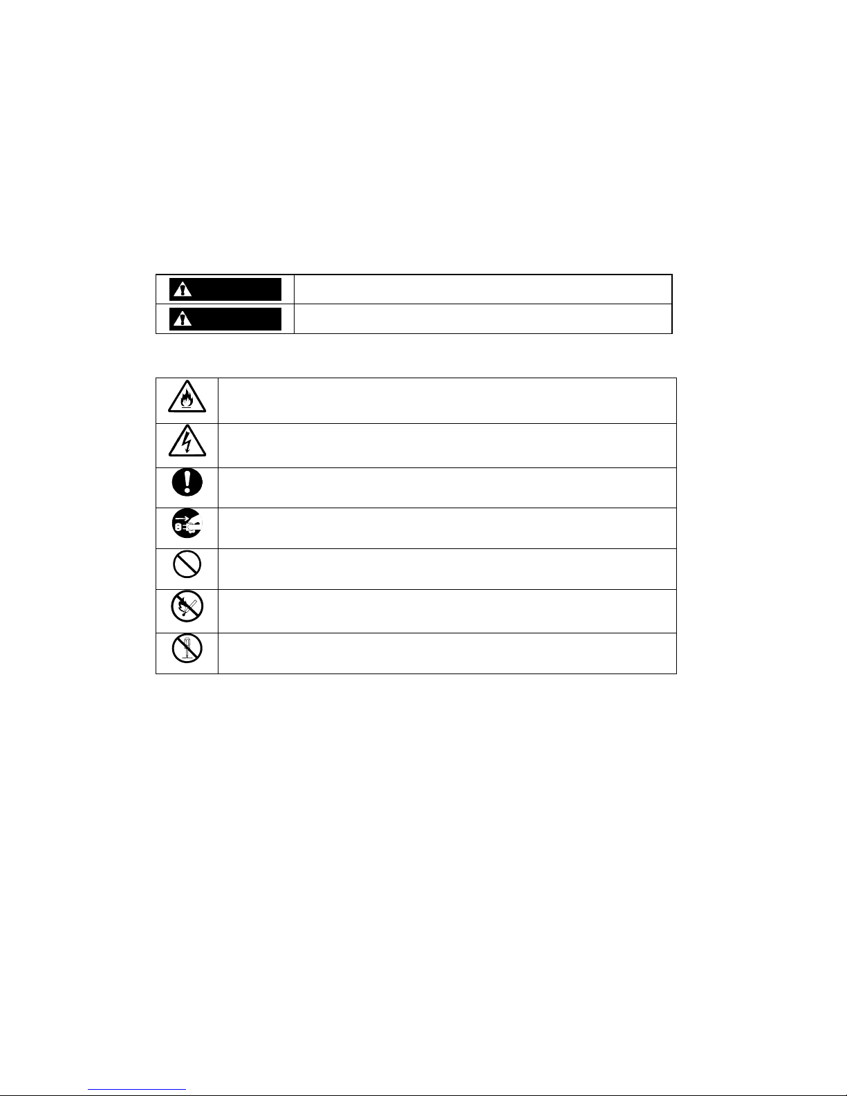
WARNING
Indicate there is a risk of death or serious wound.
CAUTION
Indicate there is a risk of burn or injury.
Risks and necessary actions to reduce risks are indicated individually by the following symbols.
Indicates the risk of smoke emission or fire outbreak.
Indicates the risk of electric shock.
Indicates required general actions for operators.
Indicates instructions to pull out the plug of a power cord from outlet.
Indicates notice of general prohibition.
Indicates instructions to keep a device away from inflammable object.
Indicates the danger of an injury due to harmful material.
Page 5
iv
Notes on Use
The following includes information necessary for proper and safe operation of the disk array unit.
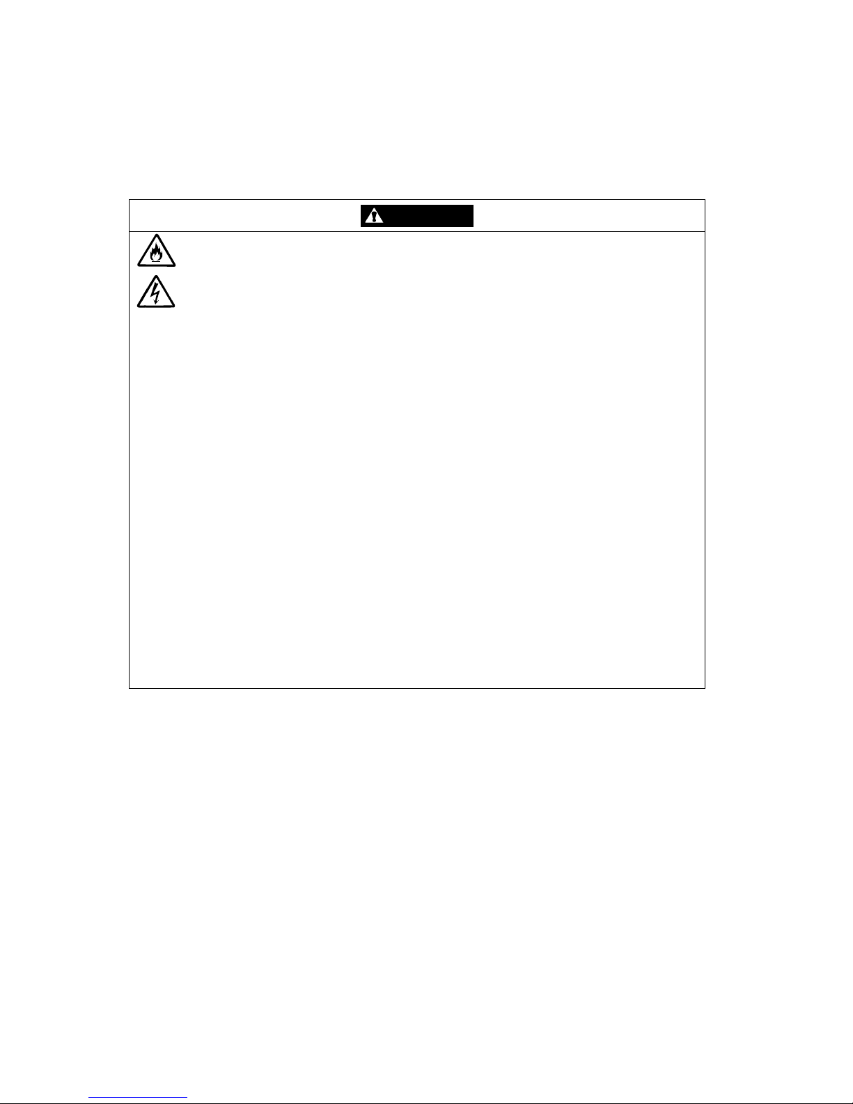
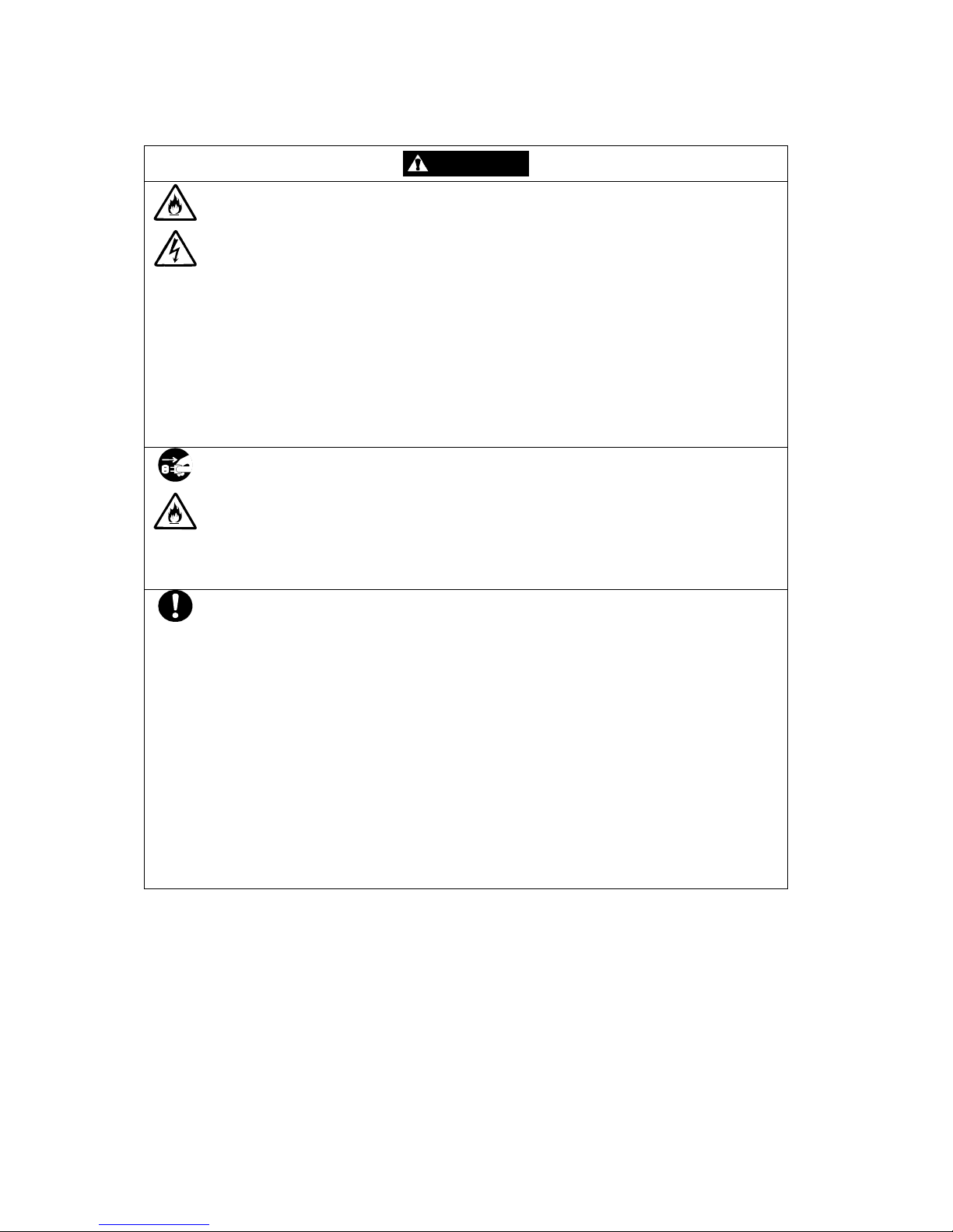
WARNING
Do not use the disk array unit in an area with much moisture or water usage. If so,
a fault, electrical shock, or fire may occur.
Do not use the disk array unit in an area where inflammable gas and/or
combustible substance are placed. If so, fire or explosion may occur.
Do not concentrate power cords only to some AC outlets. If so, fire may occur.
Do not put a heavy substance on a power cord. If so, the coating of the power
cord may be broken, fire may occur, and/or you may be electrically shocked.
Do not install the disk array unit in an area of much moisture or dust. Remove dust
adhering to AC outlets and the plugs of power cords, if any. If dust remains
adhering to an AC outlet and/or plug, fire may occur.
Do not connect the plug of a power cord to an AC outlet with a wet hand. If so, you
may be electrically shocked.
While the disk array unit can accept the power of 100 - 240 VAC (50/60 Hz), the
power cord coming with the disk array unit can only accept 100 – 120 VAC. Use
100 – 120 VAC (50/60 Hz) when the attached power cord is used. Using power of
different voltage may cause electric shock, smoke, and/or fire to occur.
The controller of the disk array unit contains lithium battery. Do not remove the
lithium battery. The lithium battery may explode when it is brought close to fire or
immersed in water. Dispose of the controller according to local ordinance. Contact
your local government for details.
If the disk array unit does not operate normally due to the life of the lithium
batteries, contact your service representative. Do not dis as semble the controller,
or replace or charge battery by yourself.
Page 6
v
CAUTION
Do not install the disk array unit and the host systems on unstable places. If so,
some substances may be dropped to cause you to be injured.
Do not install the disk array unit and the power cords in an area with direct sunshine
or near an apparatus generating heat such as a heater. If so, a fault may occur.
Further, the coating of the power cord may be melted to cause fire or electric shock
to occur.
Insert the plug of a power cord to an AC outlet securely. Any power cord shall be
routed with sufficient margin to avoid excess force from being given to the plugs of
the power cord or the power cord itself. If a power cord is removed from the AC
outlet during operation, data may be lost and/or a fault may occur.
To prevent electric shocks, connect a power cord to an AC outlet with earth
terminal. Connection of the earth line to a gas tube is extremely dangerous. Never
do it.
Connect or remove a peripheral device from the disk array unit after turning off all
the powers of the disk array unit and peripherals and pulling out the power cords
from the AC outlets. If not, some units may be broken and/or you may be electrically
shocked.
To carry or reinstall the disk array unit, disconnect all cables and power cords
beforehand. If not, some units may be broken, you may be electrically shocked,
and/or a fire may occur.
To install the unit in a rack, observe the following guidelines.
1. TMRA – If installed in a rack, consideration should be given to installing the
equipment in an environment compatible with the TMRA.
2. Reduced Air Flow – Installation in a rack should be such that the amount of air flow
required for safe operation of the equipment is not compromised.
3. Mechanical loading – Mounting of the equipment in the rack should be such that a
hazardous condition is not achieved due to uneven mechanical loading.
4. Circuit Overloading – Consideration should be given to the connection of the
equipment to the supply circuit and the effect that overloading the circuits might
have on overcurrent protection and supp l y wiring. Appropriate consideration of
equipment nameplate ratings should be used when addressing this concern.
5. Reliable Earthing – Reliable earthing of rack-mounted equipment should be
maintained. Particular attention should be given to supply connections other than
direct connections to the branch circuit (e.g., use of power strips).
Page 7

vi
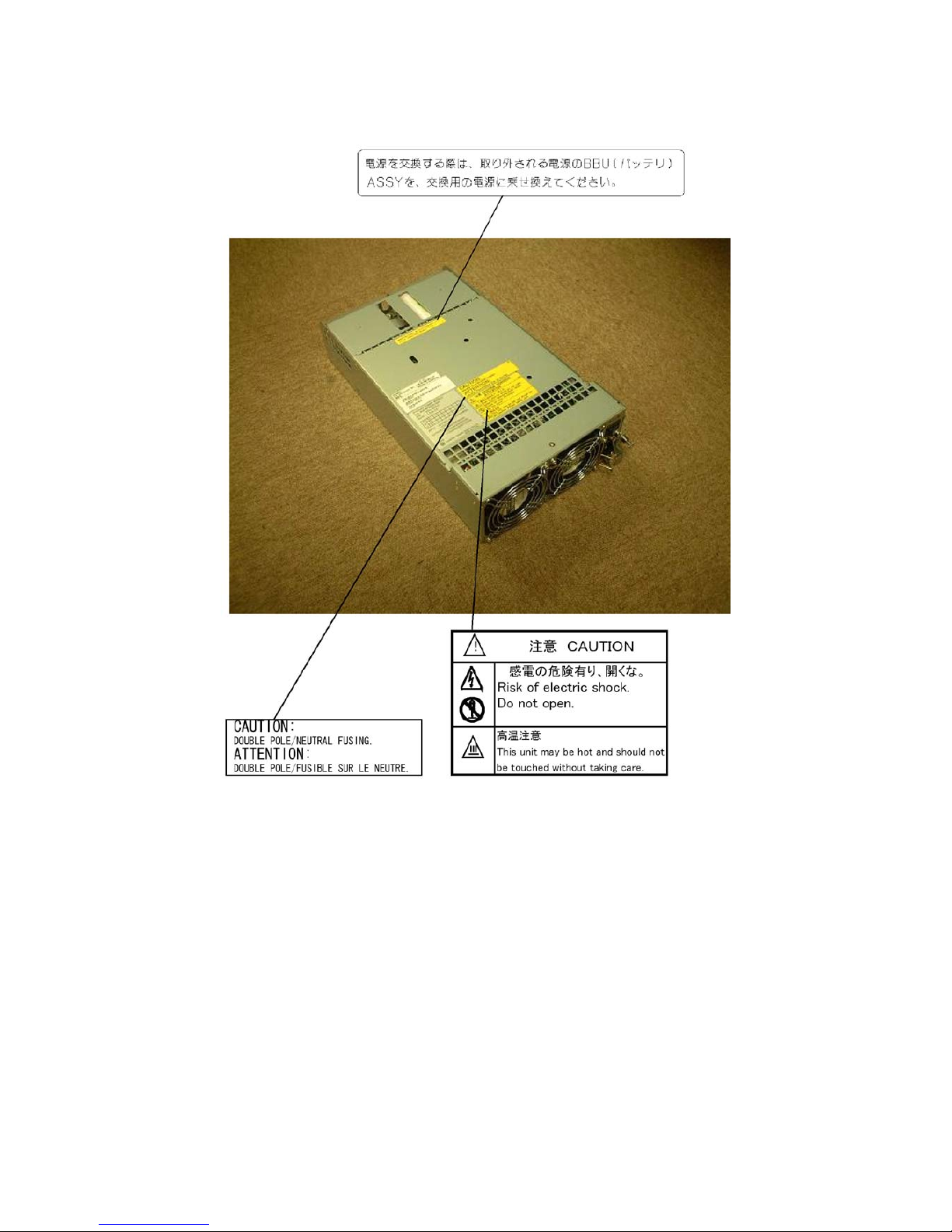
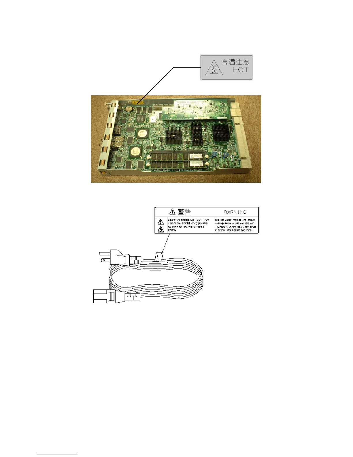
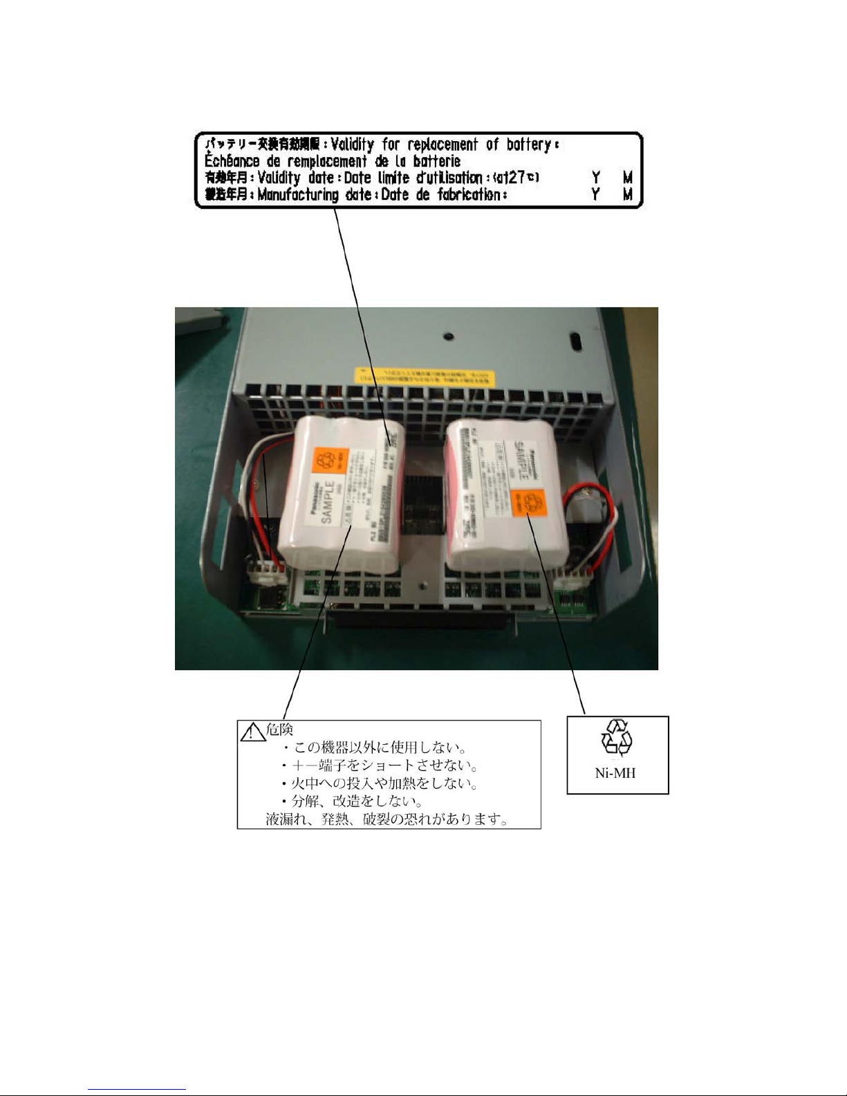
Indication on Safety
The warning label is attached to components with possible danger or their vicinity in your disk array
unit to inform the user that a hazardous situation may arise when operating the disk array unit. (Do not
intentionally remove or damage any of the labels. )
If you find any labels totally/partially removed or illegible due to damage, contact your sales
representative.
Page 8
vii
Page 9
viii
Page 10
ix
Page 11

x
Preface
Thank you very much for your purchase of the disk array unit. This manual is intended to enable you
to correctly use the disk array unit NF1400-SR40E.
Before using the disk array unit, also read the manuals of several devices including NEC Express5800
series, FibreChannel controller, NX7000/NX7700i series, FC-AL SCSI connection mechanism, or
CX5000 series to be connected with the disk array unit and the manual of the used OS.
NEC Storage BaseProduct needs to be purchased separately for using the disk array unit.
The following options are provided for the disk array unit:
Options for NF1400-SR40E:
Additional FC disk enclosure NF1400-SE42E
Additional FC disk drive (73-GB/10Krpm) NF1400-SM413E
Additional FC disk drive (147-GB/10Krpm) NF1400-SM414E
Additional FC disk drive (300-GB/10Krpm) NF1400-SM415E
Additional FC disk drive (36-GB/15Krpm) NF1400-SM422E
Additional FC disk drive (73-GB/15Krpm) NF1400-SM423E
Additional FC disk drive (147-GB/15Krpm) NF1400-SM424E
Power supply control unit NF1400-SP03
Option battery NF1400-SZ01E
To install the disk array unit in non-standard rack:
Rack mount kit NF9100-SK01E, NF9100-SK02E, and NF9100-SK03E
After reading the manual, store it in an area where you can access it easily.
First edition, December 2004
Page 12

xi
Check of Components in Package
(1) Unpacking
Open the package and take out the disk array unit and accessories from the package without large
shock. The disk array unit is greatly heavy. Accordingly, if two people or less lift the unit, their backs
may be damaged. To take out the disk array unit from the package, more than three people should
always support the bottom of the unit without holding the power supply and the projections of the
controller.
The package is specially designed for carriage of a precision device. Do not dispose of the package
because it is required to return the disk array unit to the factory for its repair.
(2) Inspection
After unpacking, check that all the components listed in the table below are provided. If any of the
components is missed, contact your sales representative. Next, inspect the disk array unit and
accessories. If any of the components is damaged, contact your sales representative.
No.
Product name
Remarks
Qty
1
NEC Storage S1400
S1400: NF1400-SR40E
1 2 Power cord
Length 5 m (for 200 VAC)
2 3 Front mask
With security key
1 4 User's Guide (this document)
1 5
Rack mount kit
For NEC Storage rack (L and R)
1
6 Program SystemGlobe NEC Storage BaseProduct
Ver3.3 - NEC Storage S1400
1
7 Packing list 1
Page 13
xii
NF1400-SR40E
(1) NEC Storage S1400 (The figure above shows
the unit with the front mask installed.)
(2) Power cord (x2)
(3) Front mask (4) User's Guide
(5) Rack-mount kit (6) Programs
(7) Packing list
Page 14
xiii
Legend
Symbols in the Text
This User's Guide uses the following symbols to indicate improper handling which may cause the disk
array unit to be defected or frozen.
Symbol Description
If the description is ignored to handle the disk array unit, the unit may be
defected, some software used in the unit may be broken, and/or the data
created by the user may be broken.
If the description is ignored to handle the disk array unit, the unit may be
defected and/or some software used in the unit may not operate normally.
This User's Guide also uses the following symbol.
Symbol Description
Supplement of the text
This User's Guide uses the following terms to indicate specific devices.
Disk array unit
Indicates NF1400-SR40E.
Disk enclosure
Indicates the additional FC disk enclosure NF1400-SE42E
(sold separately).
Disk drive Indicates the hard disk drive with dedicated tray.
Dummy tray Indicates the dedicated tray only, with no hard disk drive
installed.
Host system Indicates the NEC Express5800 series, NX 7000/NX7700i
series, or CX5000 series.
Host bus adapter Indicates the FibreCha nne l c ontroller for NEC Express5800
series, FC-AL SCSI connection mechanism for
NX7000/NX7700i series, or FibreChannel controller for
CX5000 series.
Page 15

xiv
Contents
1.
Notes on Installation and Handling of Disk Array Unit ......................................... 1-1
1.1 Note on Carrying Disk Array Unit .................................................................................... 1-1
1.2 Environment in Use of Disk Array Unit ............................................................................ 1-2
1.3 Installation and Connection of Disk Array Unit ................................................................ 1-3
1.4 Notes on Use of Disk Array Unit....................................................................................... 1-4
1.5 Routine Inspection of Disk Array Unit .............................................................................. 1-5
1.6 Notes on Storage or Carriage of Disk Array Unit .............................................................. 1-6
2. Features of Disk Array Unit .................................................................................... 2-1
2.1 Hot Spare Feature .............................................................................................................. 2-2
2.2 Write Cache Feature .......................................................................................................... 2-3
2.3 Program Product ................................................................................................................ 2-4
2.4 Management Software ....................................................................................................... 2-4
2.5 Updating of Control Software ........................................................................................... 2-4
2.6 RAID Configuration .......................................................................................................... 2-5
3. Names and Roles of Sections ................................................................................ 3-1
3.1 Front View ......................................................................................................................... 3-1
3.2 Rear View .......................................................................................................................... 3-3
3.3 Power Supply..................................................................................................................... 3-5
3.4 Controller ........................................................................................................................... 3-7
3.5 Battery Backup Unit ........................................................................................................ 3-10
3.6 Power Control Card (NF1400-SP03E) ............................................................................ 3-11
4. Installation and Connection Procedures ............................................................... 4-1
4.1 Installation and Connection Procedures ............................................................................ 4-1
5. Connection of Disk Array Unit ............................................................................... 5-1
5.1 Notes on Connection of Disk Array Unit .......................................................................... 5-2
5.2 Connection of Disk Array Unit .......................................................................................... 5-3
5.3 Connection of Disk Array Unit as Additional Unit ........................................................... 5-7
5.4 Connection of Ethernet Cable.......................................................................................... 5-11
5.5 Connection of Power Cords ............................................................................................. 5-12
6. Addition of Optional Devices ................................................................................. 6-1
6.1 Addition of Disk Drive ...................................................................................................... 6-1
6.2 Addition of Disk Enclosure ............................................................................................... 6-6
6.3 Addition of Optional Battery ........................................................................................... 6-12
6.4 Addition of Power Control Card ..................................................................................... 6-19
7. Handling of Disk Array Unit .................................................................................... 7-1
7.1 Notes on Handling of Disk Array Unit .............................................................................. 7-1
7.2 Power On/Off of Disk Array Unit ..................................................................................... 7-2
7.3 LD (Logical Disk) Setting Procedure ................................................................................ 7-6
7.4 Spare Disk Setting Procedure ............................................................................................ 7-6
8. Action Taken at Occurrence of Fault or Error ....................................................... 8-1
Page 16

xv
8.1 Countermeasures Taken when Occurrence of a Fault is Suspected ................................... 8-2
8.2 Indication at Occurrence of Fault ...................................................................................... 8-4
8.3 Failure of Controller .......................................................................................................... 8-5
8.4 Failure of Power Control Card .......................................................................................... 8-9
8.5 Failure of Power Supply .................................................................................................. 8-11
8.6 Failure of Battery Backup Unit ....................................................................................... 8-16
8.7 Failure of Disk Drive ....................................................................................................... 8-17
8.8 Check of Type Name and Manufacturing Numbers ........................................................ 8-20
8.9 Computer V irus................................................................................................................ 8-22
8.10 Preparation before Phone Call ......................................................................................... 8-22
8.11 Service and Support ......................................................................................................... 8-22
8.12 Unit Life/Repair Service Period ...................................................................................... 8-23
8.13 Disposal of Disk Array Unit ............................................................................................ 8-23
9. Product Specification ............................................................................................. 9-1
9.1 Basic Specification of Disk Array Unit ............................................................................. 9-1
9.2 Optional Components ........................................................................................................ 9-2
9.2.1 Options for NEC Storage S1400 ................................................................................ 9-2
9.2.2 Accessories common to S1400 .................................................................................. 9-2
9.3 Environmental Conditions ................................................................................................. 9-3
9.4 Power Specification ........................................................................................................... 9-3
9.5 External Dimension and Weight ........................................................................................ 9-3
9.6 Life Expectancies of Components ..................................................................................... 9-3
Appendix A Features of Disk Array Unit ............................................................... A-1
1. Battery Backup ...................................................................................................... A-1
2. Repair Time ............................................................................................................ A-1
3. Logical Disk Capacity ............................................................................................ A-2
3.1 Arbitrary Logical Disk Capacity ...................................................................................... A-2
3.2 Maximum Logical Disk Capacity..................................................................................... A-2
4. Access Control ...................................................................................................... A-2
4.1 Port Mode ......................................................................................................................... A-3
4.2 WWn Mode ...................................................................................................................... A-3
5. Dynamic Data Replication ..................................................................................... A-3
6. Miscellaneous Settings ......................................................................................... A-4
7. Various Default Values .......................................................................................... A-4
8. Notes on Use of DynamicDataReplication ........................................................... A-4
9. Setting of OS Type ................................................................................................. A-5
10. Program Product ............................................................................................. A-5
11. Updating of Control Software ......................................................................... A-6
12. Snap Shot ........................................................................................................ A-6
Page 17

xvi
12.1 Note on Using Snap Shot ................................................................................................. A-6
Appendix B Installation Procedure ....................................................................... B-1
1. Creation of Logical Disks ...................................................................................... B-1
1.1 Binding Logical Disk ....................................................................................................... B-1
Appendix C Use of Maintenance PC ..................................................................... C-1
1. Initialization by Maintenance PC ........................................................................... C-1
1.1 Connection of Maintenance PC ........................................................................................ C-1
1.2 Configuration .................................................................................................................... C-4
1.2.1 Port Configuration .................................................................................................... C-4
1.2.2 FC Port Configuration .............................................................................................. C-5
1.2.3 Resource Configuration ............................................................................................ C-8
2. Confirmation of Unit Setup .................................................................................. C-11
2.1 Activation on Modification of FC Port Configuration ................................................... C-11
2.2 Confirmation of FC Port Configuration ......................................................................... C-12
2.3 Confirmation of Resource Configuration ....................................................................... C-13
Appendix D Installing Unit on Rack ...................................................................... D-1
1. Installing New Rack-mount Kit (Accessory) on NEC Storage Rack ................... D-1
2. Installing Rack-mount Kit (Accessory) on NEC Storage Rack ........................... D-5
2.1 Installation of Rails ........................................................................................................... D-5
2.1.1 Angle Hole Fitting Rail ............................................................................................. D-6
2.1.2 Round Hole Fitting Rail .......................................................................................... D-12
3. Installing Unit on HP Rack................................................................................... D-18
3.1 Installation of Rails ......................................................................................................... D-18
3.2 Installation of Rack Nuts ................................................................................................ D-22
3.3 Installation of Unit .......................................................................................................... D-23
4. Installing Unit on Sun StorEdge Rack ................................................................ D-24
4.1 Installation of Rails ......................................................................................................... D-24
4.2 Installation of Unit .......................................................................................................... D-26
5. Installing Unit on Express Old-type Rack .......................................................... D-27
5.1 Installing the Rack Mount Kit ........................................................................................ D-28
5.2 Installation of Unit .......................................................................................................... D-29
6. Cable Wiring ......................................................................................................... D-30
Page 18
1-1
1. Notes on Installation and Handling of Disk Array
Unit
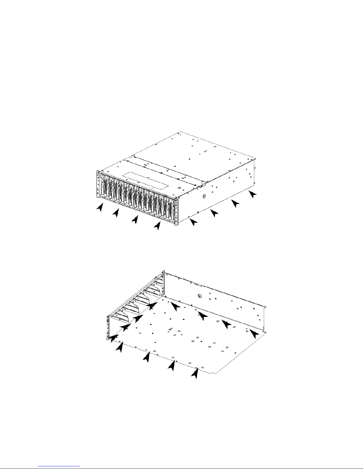
1.1 Note on Carrying Disk Array Unit
Be sure to hold the bottom the disk array unit when carrying it.
Hold the front or side bottom of the disk array unit if possible.
Page 19
1-2
1.2 Environment in Use of Disk Array Unit
In installation of the disk array unit, take into account the following items on the location, room
temperature, space required for handling, ventilation, and other conditions.
Install the disk array unit indoors.
Do not expose the disk array unit to direct sunlight. Use a window shade or
curtain to block sunlight to the unit if necessary.
Install the disk array unit on a level floor with sufficient strength. In addition, do
not give shocks and/or vibrations to the disk array unit. If so, some components
may be dropped to cause the disk array unit to be defected and/or people to be
injured.
Install the disk array unit in an area under the following conditions; temperature
range between 5°C - 40°C and humidity range between 10% - 80% (without
condensation).
Do not install the disk array unit in an area with water or oil poured, area
suffering liquid such as water and oil, suffering steam, area with steam, and
area with much moisture. If so, a fault or electrical shock may occur.
Do not install the disk array unit in an area with emission of chemical steam or
an area where the disk array unit may be contact with inflammable substance.
If so, a fault, fire, or explosion may occur.
Do not install the disk array unit in an area with much dust. If so, a fault may
occur.
Do not install the disk array unit in an area with direct sunshine or near fire or
an apparatus generating heat such as stove. If so, a fault or deformation may
occur.
Do not install the disk array unit near TV, radio, and codeless telephone. Some
noise may appear in the TV, radio, and codeless telephone.
Do not use cellular phones near the disk array unit. If so, a fault may occur.
Do not install the disk array unit near a device generating strong magnetism. If
so, a fault may occur.
Install the disk array unit so that the ventilating holes opened on the front and
rear faces are not blocked. If not, heat generation and/or fault may occur.
Page 20
1-3
1.3 Installation and Connection of Disk Array Unit
WARNING
Do not use the disk array unit in an area with much moisture or water
usage. If so, a fault, electrical shock, or fire may occur.
Do not use the disk array unit in an area where inflammable gas and/or
combustible substance are placed. If so, fire or explosion may occur.
Do not install the disk array unit in an area of much moisture or dust.
Remove dust adhering to AC outlets and the plugs of power cords, if any. If
dust remains adhering to an AC outlet and/or plug, fire may occur.
Do not concentrate power cords only to some AC outlets. If so, fire may
occur.
Do not put a heavy substance on a power cord. If so, the coating of the
power cord may be broken, fire may occur, and/or you may be electrically
shocked.
Do not connect the plug of a power cord to an AC outlet with a wet hand. If
so, you may be electrically shocked.
CAUTION
Make sure to disconnect all power cords and cables before relocating the
disk array unit. If not, a malfunction of the system, an electric shock and/or
fire may occur.
While the disk array unit can accept the power of 100 - 240 VAC (50/60 Hz),
the power cord coming with the disk array unit can only accept 100 – 120
VAC. Use 100 – 120 VAC (50/60 Hz) when the attached power cord is
used. Using power of different voltage may cause electric shock, smoke,
and/or fire to occur.
Do not install the disk array unit and the power cords in an area with direct
sunshine or near an apparatus generating heat such as a heater. If so, a
fault may occur. Further, the coating of the power cord may be melted to
cause fire or electric shock to occur.
The disk array unit weighs 34 kg or more. Hold the disk array unit and disk
enclosure firmly with at least three people to carry it. Carrying the devices
only by two or less people may strain their back.
Select the place where the disk array unit can be connected to the AC outlet
by using the attached power cord.
Insert the plug of a power cord into an AC outlet securely. If some clearance
remains between the plug of the power cord and the AC outlet, dust may
enter into the clearance. This then may cause fire to occur.
Provide sufficient margins for the cables connected to the disk array unit so
that legs may not be trapped by the cables. Avoid power plugs and FC
connectors from suffering excess forces.
Do not use cables connected to the disk array unit with them leaving bent. If
so, a fault or fire may occur.
Page 21
1-4
Use the cables approved by NEC as those connected to the disk array unit
and check the destinations to which the cables are connected. In addition,
always lock power cords and FC cables when they are connected.
Use the power source independent from TV or radio. Otherwise, a noise
may be generated.
To connect a cable to the mating connector, make sure that the connector
of the cable is not damaged and any pins are not bent. Using a cable not
approved by NEC or a damaged cable may cause a fault or fire to occur.
To disconnect a cable from the mating connector, always hold the
connector of the cable. Do not hold the cable itself to disconnect it.
1.4 Notes on Use of Disk Array Unit
Do not let any animal (pet) or children touch the cable connected to the disk
array unit. Pulling the cable may cause the unit to fall down, resulting in
failure of the unit.
Do not enter any liquid such as water into the disk array unit. If so, you may
be electrically shocked or the unit may be defected. If some liquid is entered
into the disk array unit, turn off the power and contact your sales
representative or maintenance engineer. If the disk array unit seems dry,
only a small amount of liquid may remain to cause the unit to be defected.
Do not enter foreign substances such as clip and screw into the disk array
unit through the ventilating holes on the front or rear face. If so, a fault may
occur.
Do not disassemble or modify the disk array unit. If so, a fault or electrical
shock may occur. Repair of the unit will be charged regardless of warranty.
If the disk array unit will not be used for a long period, disconnect the plugs
of the power cords from the AC outlets for safety.
Disconnect the power plug from the outlet when a thunderstorm is
approaching. If it starts thundering before you disconnect the power plug, do
not touch any part of the unit including the cables. If any failure is found
later, contact your sales representative.
Page 22
1-5
1.5 Routine Inspection of Dis k Array Unit
CAUTION
To clean the disk array unit, always turn off the power and also disconnect
the plugs of power cord from AC outlets. If not, you may be electrically
shocked.
If a surface of the disk array unit becomes dirt, wipe the surface lightly with
soft cloth. Wiping the surface by using chemicals such as benzene and
thinner, or volatile chemicals, may cause the surface to be deformed or
discolored. In addition, note that splaying insecticide on a surface may
cause the surface to be deformed or discolored.
It is recommended to clean the inside of the disk array unit periodically. It is
because dust may be accumulated after the disk array unit is used for a
long time.
Contact your sales representative or maintenance engineer for the cleaning
of the inside of the disk array unit.
Users must not disassemble and/or repair the disk array unit because it is
dangerous.
Do not use any battery backup unit exceeding its life. If so, a fault or fire
may occur.
Page 23
1-6
1.6 Notes on Storage or Carriage of Disk Array Unit
Do not store the disk array unit in an area where the temperature may
increase extremely or the difference between the warm and cold states is
considerably large. In addition, do not store the disk array unit in an area
with much moisture or dust.
Note that foreign substances such as water and metals may not be entered
into the disk array unit during storage. Using the disk array unit with some
foreign substance left inside may cause a fault, electrical shock, or fire to
occur.
During the storage, do not put any substance on the disk array unit or do
not place the disk array unit on an area where the unit may be dropped.
To use the disk array unit after storage for longer than six months, it is
recommended to contact your sales representative or maintenance
engineer for inspection and/or repair.
The disk array unit weighs 34 kg or more. Hold the disk array unit firmly with
at least three people to carry it. Carrying the devices only by two or less
people may strain their back.
Make sure to package the disk array unit when transporting it with the
packing material that comes with the disk array unit. If any other packing
materials are used, a vibration or shock generated during transportation
may cause a malfunction of the unit.
F
Page 24
2-1
2. Features of Disk Array Unit
The disk array unit has the following features.
NF1400-SR40E is a high-performance disk array unit designed for NEC Express5800 (W indows 2000
/Windows Server 2003 / Turbolinux 7 Server / RedHat Linux 7.2 / Miracle Linux Standard Edition 2.1
/ RedHat Enterprise Linux AS 2.1 / RedHat Enterprise Linux ES 2.1), NX7000/NX7700i (HP-UX),
and CX5000 (Solaris) systems.
* Ask your sales representative for non-NEC servers (hosts) which are supported and compatible
operating systems.
The storage capacity of the disk array unit can be easily expanded by installing an additional FC disk
drive (option) in the expansion slot of the disk array unit.
An additional FC disk enclosure (option) to enable the expansion of the storage capacity of the disk
array unit is provided for the disk array unit.
The disk array unit supports RAID types 1, 5, 6, 10 and 50. If a fault occurs in a single disk drive (2
disk drives for RAID type 6), the disk array unit can continue the operation without loss of data.
Any defected disk drive can be replaced with a new one without system shutdown. Further, the disk
array unit has the auto repair feature which automatically starts data recovery after the replacement of
the defected disk drive.
If a single disk drive is specified as the spare disk, the data in the defected disk drive can be
immediately recovered in the spare disk. The use of this hot spare feature as well as the auto repair
feature allows the data in the defected disk drive to be automatically recovered in the spare disk as
soon as a disk drive is defected. This improves the system reliability.
The disk array unit has the cache memory data hold function by using the battery backup unit. The
function allows comfortable high-speed data processing to be done under high reliability.
Further, owing to the redundant configuration of the controller, fan, power supply, and battery backup
unit as well as disk drive, high availability is achieved.
See Section 9.2 "Optional Components" for the product names and part numbers of options.
Above features of the disk array unit are effective only for the hardware failure
(e.g., the hard disk is physically damaged or inoperative). The software failure
(e.g., the data is lost or rewritten due to program excursion) is not covered by
these features. When the software failure would occur, the system could seriously
be damaged. To minimize the damage, be sure to back up the data periodically.
Page 25
2-2
2.1 Hot Spare Feature
Spare disks can be installed in the disk array unit. If a disk drive is defected, the data in the defective
disk drive is recovered in the spare disk. After the data recovery, the disk drive operates normally if
another disk drive is defected.
A defective disk drive can be replaced without turning off the power of the disk array unit.
With the shipping default, if the disk drive defected during the operation by using the spare disk is
replaced with a normal disk drive, the replaced disk drive works as a spare disk.
The data can also be recovered in another other disk enclosure.
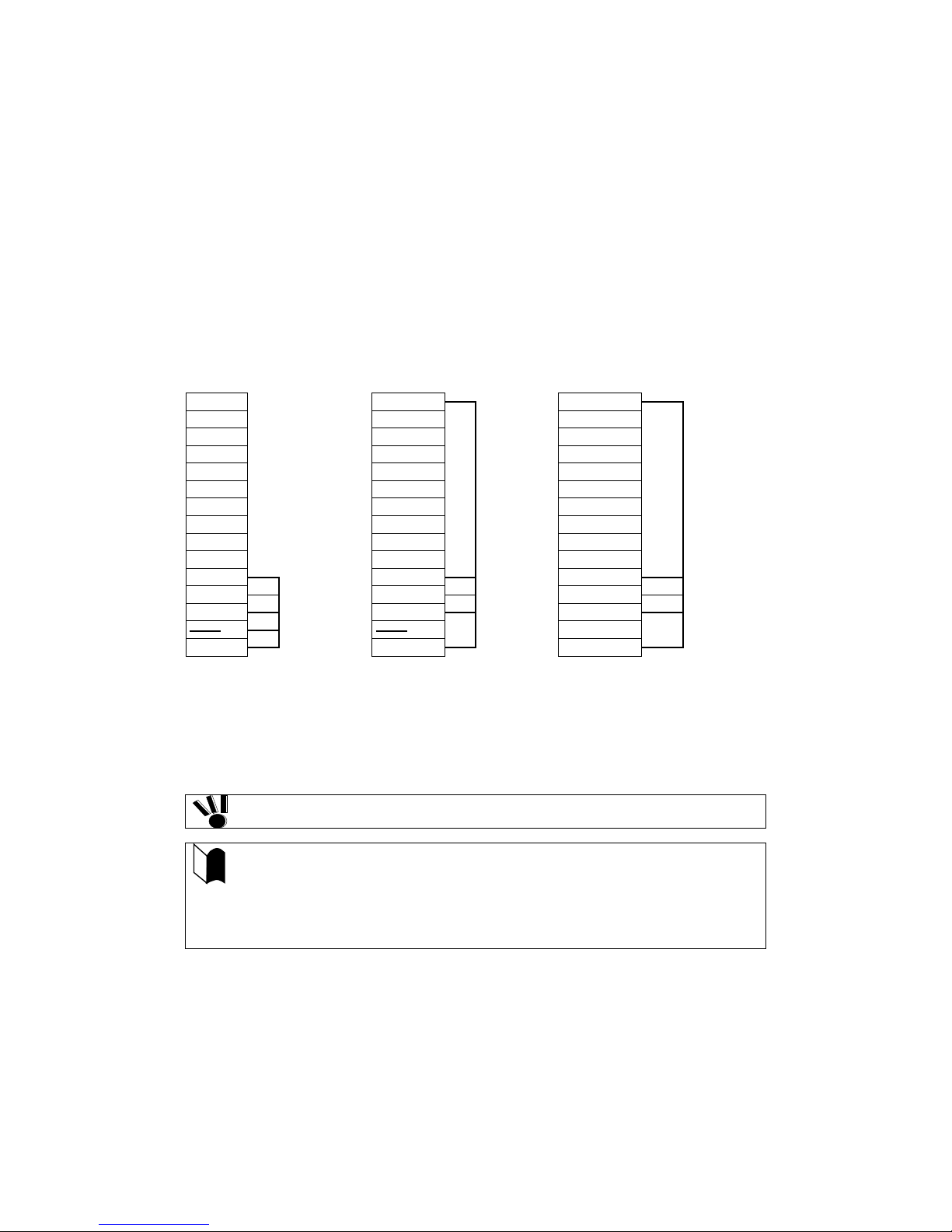
Example of hot spare operation (LDN0 RAID5)
PDN14 Spare disk PDN14
PDN14
PDN13 PDN13 PDN13
PDN12 PDN12 PDN12
PDN11 PDN11 PDN11
PDN10 PDN10 PDN10
PDN9 PDN9 PDN9
PDN8
⇒
PDN8
⇒
PDN8
PDN7 PDN7 PDN7
PDN6 PDN6 PDN6
PDN5 PDN5 PDN5
PDN4
PDN4
PDN4
PDN3
PDN3
PDN3
LDN0 RAID5
LDN0 RAID5
LDN0 RAID5
Spare Disk
PDN2
PDN2
PDN2
PDN1
PDN1
PDN1
⇐
PDN0
PDN0
PDN0
Failure in PDN1
Recovery of data
in spare disk
Replacement of PDN 1
PDN1 works as a spare disk
* PDN: Physical Disk Number
LDN: Logical Disk Number
Do not move any of the factory-installed disk drives into another slot.
The spare disk can operate only when it has a capacity and a revolution
equal to the defected disk drive.
If disk drives having different capacities and/or revolutions coexist, spare
disks of the different capacities and/or revolutions are defined to manage the
disk drives clearly.
Up to 32 spare disks may be installed in the entire disk array unit.
Page 26
2-3
2.2 Write Cache Feature
For RAID type 5, 6, or 50, the performance of the disk array unit may be decreased during writing of a
small amount of data. It is because the previous data and parity data must be read to recalculate the
parity.
The disk array unit is equipped with cache memory. When write data is stored in the cache memory,
the disk array unit terminates the command processing and then writes the data to disk drive for
improving the performance.
The cache memory is backed up with the battery backup unit. To increase data security,
an uninterruptible power supply (UPS) should also be used.
In general, if the power is shut down before the data saved in the cache memory is written to disk
drive, the data in the cache memory will be lost. To prevent this, the disk array unit provides the
battery backup by battery backup unit installed in the power supply to retain data in the cache memory.
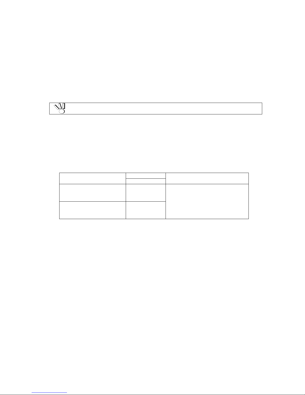
The backup time using the battery backup unit is res tri cted as follow s :
The backup time of battery backup unit depends on the number of battery backup units installed. The
following table shows the backup time when the battery backup units are installed and they are fully
charged.
Number of Battery Backup
Units Installed
Period of Service
Operating Conditions
Up to 5 years
Standard configuration
(Optional batteries not
provided)
24H 8-hour charging (power-on) and
16-hour discharging (power-off) in
environment in which the ambient
temperature is @25
o
C
Expansion configuration with
optional batteries
(Optional batteries provided)
72H
* If the discharging (power-off) time exceeds 16 hours in daily use, the battery back units
need to be replaced at a cost before they reach the service life of 5 years. Ask your
NEC sales representative for the relation between the operation mode and the life of a
battery backup unit.
The following conditions are imposed to make the write cache feature effective:
The disk array unit is operating normally with the following components being installed:
– 2 controllers (or 1 controller if you have made the setting to enable Write Cache from the
maintenance PC)
– 1 or more power supplies
– 1 or more battery backup units installed in the power supply or power supplies above
(BBU0 for PS0 and BBU1 for PS1)
The battery backup units are fully charged.
If any of the conditions is not satisfied, the write cache feature does not work sufficiently.
The batteries installed in the battery backup unit are fully charged for about eight hours.
Page 27
2-4
2.3 Program Product
To use the disk array unit, the following program product is required:
For S1400:
SystemGlobe NEC Storage BaseProduct Ver3.3 (or later) - NEC Storage S1400
To use the disk array unit, release the license lock using the license code that is provided with
"SystemGlobe NEC Storage BaseProduct Ver3.3 - NEC Storage S1400 ".
A maintenance person is responsible for releasing the license lock of "SystemGlobe NEC Storage
BaseProduct Ver3.3 -NEC StorageS1400 " during the installation of the disk array unit. Please give the
person the license code provided with the product.
Before the disk array unit can be used, the license lock must be released by using the
license code provided with NEC Storage Base Pr oduct .
Be sure to release the license lock. A disk array unit with the license lock being locked
cannot receive any maintenance services because the operation cannot be
guaranteed.
For any other program product available for the disk array unit, ask your sales representative.
2.4 Management Software
SystemGlobe NEC Storage BaseProduct Ver3.3 (or later) - NEC Storage S1400 or the management
software WebSAM NEC Storage Manager can be used to allow the host system to display the
resources in the disk array unit in the real time mode.
NEC Storage Manager also enables you to set the following parameters through the host computer:
Setting of RAID configuration (RAID 1, 5, 6, 10, 50, and hot spare disk)
Resetting of RAID configuration
Downloading firmware
Collection of error log
2.5 Updating of Control Software
The disk array unit may upgrade the version of storage control software when a function or the like is
additionally installed.
You can use the added function by updating the storage control software of which version has been
upgraded.
You can update the storage control software by yourself. However, if you fail to update it, the disk
array unit can no longer operate at the worst.
NEC maintenance service representative provides the installation service (additionally charged) for
updating the storage control software. It is strongly recommended that you should ask your
maintenance service representative who has technical knowledge to update it.
Page 28

2-5
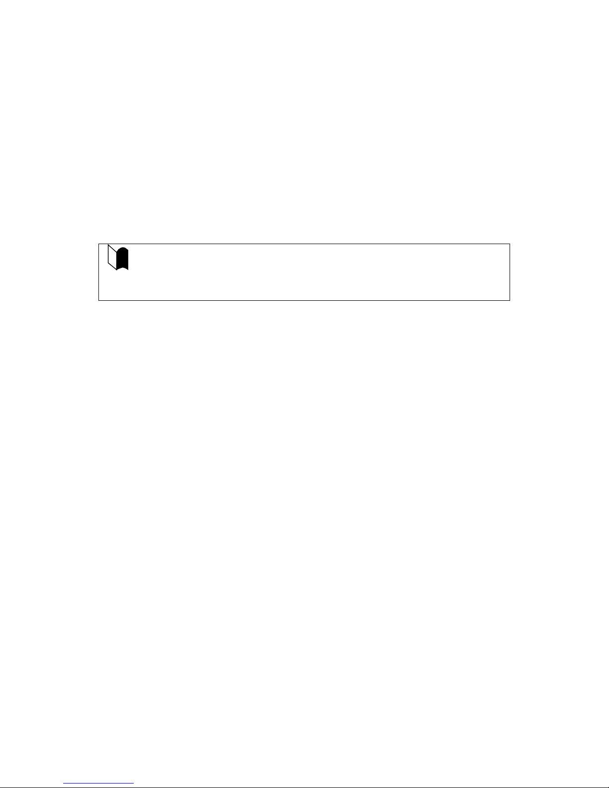
2.6 RAID Configuration
The RAID configuration in the disk array unit can be used in the combinations shown in the table
below. (G = 1000^)
RAID type
RAID1
RAID5
RAID6 *1
RAID10
RAID50
Number of logical drives in
configuration
1+1 4+1 6 to 120 2x2, 4x2, 8x2 5x2, 5x4
Number of logical drives per
subsystem
1,024 max.
Storage capacity per logical drive
(When 73-GB disk drive is used)
71.6GB 286.4GB 286.4GB
to 6.7TB
143.2GB to
572.8GB
572.8GB to
1145.6GB
* A combination of disk drives of the same capacity and same rotational speed is required for configuring logical
drives.
*1 Two modes (66%-mode and 80% mode) can be selected according to capacity efficiency.
The RAID types have the following characteristics.
Level
Function
Advantage
Disadvantage
RAID1
Mirroring
High reliability
High cost
RAID5 Striping of data and
redundant data
High capacity efficiency Low-speed data
writing
RAID6 Striping of data and
redundant data
High reliability that allows continuous
operation even when doubly failed.
Capacity can be expanded for every
drive.
Low-speed data
writing
RAID10
Striping of RAID-1
High-speed data read/write
High cost
RAID50 Striping of RAID-5 High-speed data read
High capacity efficiency
High induction cost
F
Page 29
3-1
3. Names and Roles of Sections
This chapter describes the names and functions of the sections in the disk array unit.
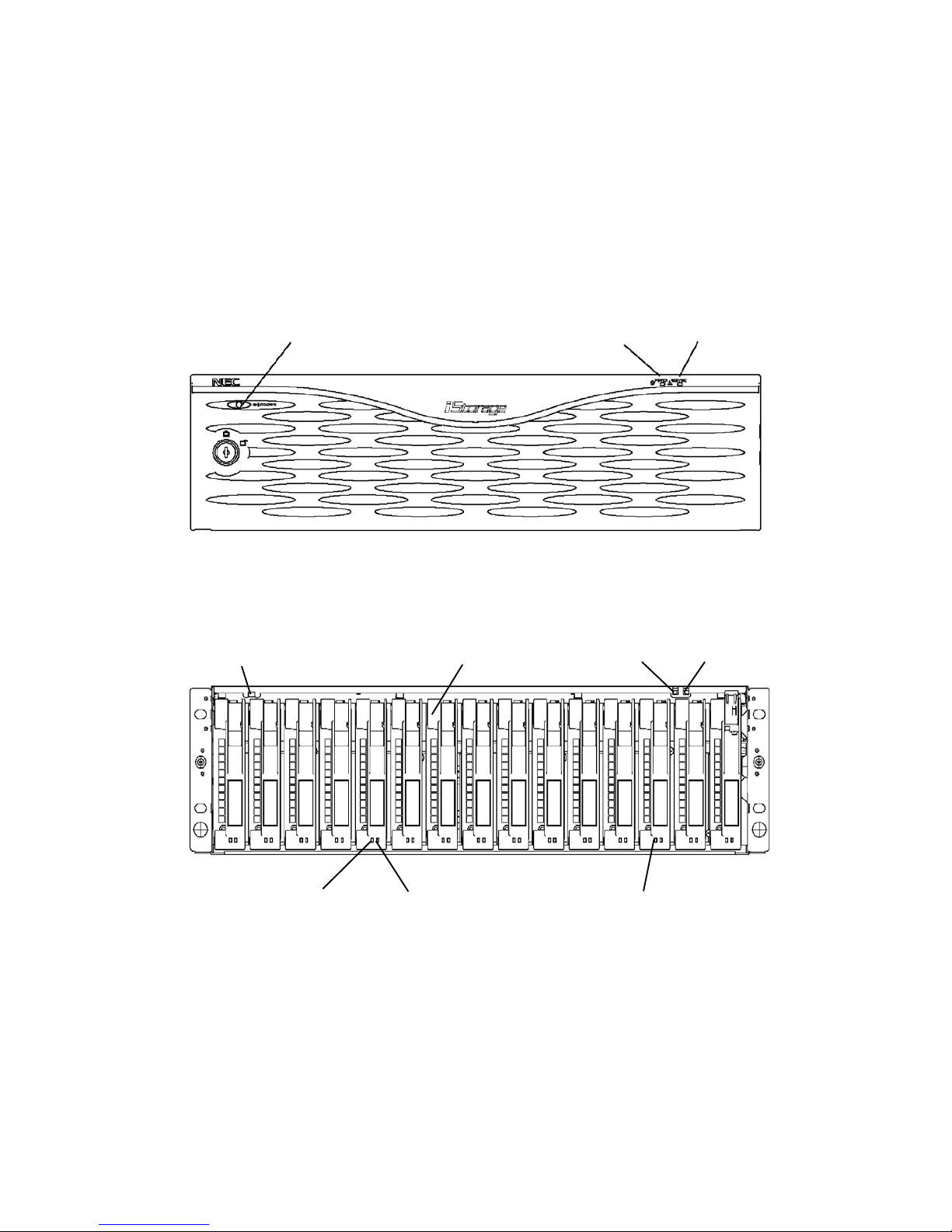
3.1 Front View
A front mask is installed on the front face of the disk array unit as shown in the figure above.
The front mask can be removed by releasing the lock with the accessory key and pulling out toward
you with your hands hooked on the both sides of the mask.
Removing the front mask, you can view the disk drives shown in the figure below.
(5) SHUTDOWN switch
(1) POWER LED
(2) SERVICE LED
(3) SHUTDOWN switch
(7) Ejector
(1) POWER LED
(2) SERVICE LED
(6) Hard disk FAULT LED
(5) Hard disk READY LED
(4) Disk drive/dummy tray
Page 30
3-2
(1) POWER LED (green)
The POWER LED lights green if the AC power is supplied and the power switch is set to ON. The
LED is off if the power switch is set to OFF.
(2) SERVICE LED (orange)
The SERVICE LED lights orange when the disk array unit or a disk array unit component including an
additional FC disk enclosure (if installed) fails. The LED flashes during the self-test and initialization
immediately after the power is turned on.
The LED goes off when the disk array unit has started, and it is off while the disk array unit is
operating normally.
(3) SHUTDOWN switch
Use this switch to turn off the disk array unit. Turning on this switch starts writing the cache data
remaining in the array controller into disk drive.
To power off the disk array unit, see "7.2 Power On/Off of Disk Array Unit" for details.
Data backed up will be lost if a controller, power supply, or battery is replaced in the
following conditions:
The scheduled stop procedure using the SHUTDOWN switch is not performed.
There are not any power supplies that are supplying power to the array controller
normally.
(4) Disk drive / dummy t ray
Disk drive: A hard disk drive (HDD) with a dedicated tray is installed.
Dummy tray: Only a dedicated tray with no HDD being installed
(5) Hard disk drive READY L ED (green)
The READY LED lights green while the disk drive is operating normally, and flashes while the disk
drive is transferring data.
This LED also flashes during the self-test and initialization immediately after the power is turned on.
(6) Hard disk dr i ve FAULT LED (orange)
The FAULT LED lights when the disk drive fails.
The LED is off while the disk drive is operating normally.
(7) Ejector
Use the ejector to install/remove the disk drive or dummy tray.
In general, secure the disk drive and dummy tray to the frame.
When inserting the disk drive into the disk enclosure, push it as far as it will go and then
lock the ejector.
Incorrect insertion may cause malfunction.
Page 31

3-3
3.2 Rear View
(1) Power supply (PS0)
(2) Controller (CONT0)
(2) Controller (CONT1)
(1) Power supply (PS1)
(4) Fan
(4) Fan
(5) Power control mechanism (PCC) or dummy assembly
(3) Battery backup unit (standard configuration)
(1) Power supply
(3) Battery backup unit (option)
Page 32

3-4
(1) Power supplies (PS0/PS1)
The power supplies are provided to supply power to the disk array unit. See Section 3.3 "Power
Supply" for details.
(2) Controllers (CONT0/CONT1)
The controller boards are provided to control the disk array unit. See Section 3.4 "Controller" for
details.
(3) Battery backup unit (BBU1/BBU0)
The battery back units are provided to protect data in the cache memory when a power failure occurs.
In the standard configuration, one battery backup unit is installed in each power supply.
The battery backup units are also provided as optional batteries (NF1400-SZ01E,) for the expansion
configuration.
See "3.5 Battery Backup Unit" for details.
(4) Fans (FAN1-[0]/FAN1-[1]/FAN0-[0]/FAN0-[1])
The fans are provided to prevent the heat-up of the overall system.
When the power switch is set to ON, four cooling fans are rotating. Note that the ventilating holes are
not blocked.
Install the disk array unit so that the ventilating holes may not be blocked. If either or
both of the ventilating holes are blocked, the internal temperature of the disk array
unit may increase to cause a fault to occur.
The disk array unit is equipped with four fans. Even if a fan fails, the air-cooling
conditions for the entire disk array unit are satisfied. However, to guarantee the
safety operation of the disk array unit, replace the power supply immediately if a fan
failure occurs.
(5) Power control card (PCC)
A power control card can be additionally installed as an option for the NF1400-SR40E only. In the
standard configuration, a dummy assembly is installed as a cover in place of the power control card.
When the disk array unit is turned OFF, the power control card is used for writing the remaining cache
data from the disk array unit into the disk drive according to the instructions from the external power
controller.
See "3.6 Power Control Card" for details.
Page 33

3-5
3.3 Power Supply
(1) P ow er plug
The power plug is intended to supply power to the disk array unit. Connect the attached power cord to
the power plug and the plug of the power cord to an outlet of 100 VAC power at 50 or 60 Hz.
The disk array unit has the redundant power configuration to prevent the entire unit from being shut
down by a single failure. In this configuration, connect two power cords in use of the disk array unit.
While the disk array unit can accept the power of 100 - 240 VAC (50/60 Hz), the
power cord coming with the disk array unit can only accept 100 VAC. Use 100
VAC (50/60 Hz) when the attached power cord is used. Using power of different
voltage may cause electric shock, smoke, and/or fire to occur.
(2) Power switch
The power switch is used to turn on/off the power of the disk array unit.
The disk array unit has the redundant power configuration to prevent the entire disk array unit from
shutting down due to a single failure. Therefore, turn on/off the two power switches when operating
the disk array unit.
(3) POWER GOOD LED
(4) POWER FAULT LED
(2) Power switch
(1) Power plug
(5)Power cord stopper
(6) Ejector
Page 34

3-6
(3) POW E R GOOD LED (green)
The POWER GOOD LED lights green when the AC power is supplied to the disk array unit and the
power switch is set to ON. The LED is off if the power switch is set to OFF or a fault occurs in the
power supply or the fan.
(4) POWER FAULT LED (orange)
The POWER FAULT LED lights if a fault occurs in the power supply, the fan, or the installed battery
backup unit. The LED is off while in normal operation.
(5) P ow er cord stopper
The power cord stopper prevents the power cord from being removed unexpectedly.
NOTE:
(6) Ejector
The shape of the power cord stopper may be different
from the figure here. See "5.5 Connection of Power Cords".
Use the ejector to install/remove the power supply.
To use the ejector, loosen the screw that secures the ejector.
When inserting the power supply into the disk array unit, push it as far as it will go
and then secure it with the screws.
Incorrect insertion may cause a power supply failure again.
A power supply or battery backup unit must be replaced within five minutes. To do
so, prepare a replacement power supply or battery backup unit before you start
the replacement procedure.
The disk array unit includes the following heating elements:
A) Disk drives
B) Power supplies
C) Controllers
The power supplies contain cooling fans.
Therefore, if you leave the disk array unit with a power supply being removed, the
disk drives in the unit may heat up causing serious trouble in reliability.
Page 35

3-7
3.4 Controller
(1) FAULT LED (orange)
The FAULT LED lights orange if a fault occurs in the controller.
(2) BATTERY BACKUP LED (orange)
With no power supplies for controller supplying power normally in such a case as power interruption,
the BATTERY BACKUP LED lights orange if the cache memory is subject to battery backup.
The warning "Do not remove the controller while the "BAT" LED is on." is printed on
the CONT chassis. However, if you have performed the scheduled stop procedure
using the SHUTDOWN switch, you can replace the controller even while the
BATTERY BACKUP LED (BAT) is on.
(3) SVP LED (green)
The SVP LED flashes green when the Status Monitoring processor (SVP) in the controller operates
normally.
(4) DIR LED (green)
The SVP LED flashes green when the Director Control processor (DIR) in the controller operates
normally.
(5) MC ACS LED (green)
The MC ACS LED lights when the Event Logging Tool (SD) card is being accessed.
(12)LINKUP LED
(12) LINKUP LED
(14)ACCESS LED
(13)LINKUP LED
(13)LINKUP LED
(14)ACCESS LED
(1) FLT LED
(2)BAT
(4)DIR
(3)SVP
(7)MODEM
(17) Ejector
(8) MNT
(9) LAN
(16) LAN
(10) FC connector
(for additional FC disk
enclosure)
(11) FC connector
(for host bus
adapter)
(6)Slot for Event Logging Tool
(5) MC ACS LED
(15) DISK LINK
Page 36

3-8
(6) Slot for Event Logging Tool
Use this slot to insert the SD card, which stores the events logged in controller.
(7) Modem connector
Don’t use for the un-support.
(8) MNT connector
Use this connector to connect with maintenance PC.
(9) LAN connector
Use this connector to connect with LAN for WebSAM NEC Storage Manager and SNMP.
(10) FC connector (for additional FCdisk enclosure) (DP0/DP1)
The FC connectors are used to connect the array controller with the additional FC disk enclosure.
See Chapter 4 "Connection of Disk Array Unit" for the cable connection.
(11) FC connector (for host bus adapter) (HP0/HP1)
The FC connectors are used to connect the host system with the disk array unit.
See Chapter 4 "Connection of Disk Array Unit" for the cable connection.
(12) LINKUP LED (DL0/DL1)
A LINKUP LED lights if the respective FC connector (FC port for additional FC disk enclosure)
becomes operable (to link up). DL0 and DL1 LEDs correspond to DP0 and DP1 connectors,
respectively.
These LEDs flash during the self-test or initialization just after power-on.
(13) LINKUP LED (HL0/HL1)
A LINKUP LED lights if the respective FC connector (FC port for host bus adapter) becomes operable
(to link up). HL0 and HL1 LEDs correspond to HP0 and HP1 connectors, respectively.
These LEDs flash during the self-test or initialization just after power-on.
(14) ACCESS LED (HA0/HA1)
The ACCESS LED lights when an I/O access to the respective FC port for host bus adapter
(HP0/HP1) occurs.
(15) DISK LINK LED (DISK LINK)
A DISK LINK LED lights if the internal FC port for the built-in disk enxlosure in the disk array unit
becomes operable (to link up).
This LED flashes during the self-test or initialization just after power-on.
Page 37

3-9
(16) LAN LINK LED (L/A)
The LAN LINK LED lights when the LAN receives a link pulse from Ethernet. This LED lights also
while the LAN port operates normally.
These LEDs flash during the self-test or initialization just after power-on.
(17) Ejector
The ejector is used to install or remove the controller. Loosen the screw before using the ejector.
When inserting the controller into the disk array unit, push it as far as it will go and
then secure it with the screws.
Incorrect insertion may cause malfunction.
Page 38

3-10
3.5 Battery Backup Unit
BBU (Standard) BBU (Option)
(1) Connector
The connector is used to connect the battery backup unit with the power supply.
Note the following points on replacing or add itiona lly installing a battery backup
unit:
– A replacement or additional battery backup unit must be of the type used in the
standard configuration.
– The standard battery backup unit must be installed on the left side. (See the
figure above.)
– The optional battery backup unit must be installed on the right side. (See the
figure above.)
The batteries are not enabled unless a battery backup unit is installed at the
standard battery location. They are not enabled either if a battery backup unit is
installed only at the optional battery location.
When installing the battery backup unit in the power supply, push in the connec tor
until it is locked.
If the connector is not fully inserted, the battery backup unit may not be enabled.
(1) Connector
Page 39

3-11
3.6 Power Control Card (NF1400-SP03E)
NOTE: The power control card is an option for the
NF1400-SR40E only.
(1) FAULT LED (FLT LED) (orange)
The FAULT LED lights orange when the power control card fails.
(2) READY LED (RDY LED) (green)
The READY LED lights green while the power control card is operating normally.
(4)NX AOC power
control connector
(3)UPS connector
(2)RDY LED
(1)FLT LED
Page 40

3-12
(3) UPS connectors (UPS0/UPS1 connector)
If the system is configured for receiving AC power from an uninterruptible power supply (UPS), the
UPS connector is used as a signal connection connector in order to link up with the UPS.
If you configure a system using UPS, stable system operation is ensured even if an unexpected power
failure or a momentary AC power failure occurs.
Ask your NEC sales representative for the system configuration using UPS.
For the reconnection of the system after configuration, ask your NEC maintenance
service representative who has technical knowledge. If you reconnect the system
by yourself, the UPS may not function normally when it is started due to a power
failure, thereby stopping system operation or losing data.
Disk array unit
AC power
AC power
Output 1
Output 2
Output 1
Output 2
UPS-UPS
straight cable
To power
control
To power
control
UPS configuration (sample)
Page 41

3-13
(4) NX AOC connector (P1 connector)
This connector is used to connect the automatic operation controller (AOC) of the NX7000/NX7700i
system in order to provide power control.
<Example of connection>
Disk array unit
(Power control card)
Automatic operation
controller (AOC)
NX7x00 server
NX7x00 system
Interface
NEC Storage-AOC cable
When inserting the power control card into the disk array unit, push it as far as it will
go and then secure it with the screws.
Incorrect insertion may cause malfunction.
F
Page 42

4-1
4. Installation and Connection Procedures
This chapter describes the procedure for the installation and connection of the disk array unit. In
general, follow the procedure shown in Section 4.1 for the installation and connection of the disk array
unit.
Take care of the matters described in Chapter 1 "Notes on Installation and Handling of Disk Array
Unit" in doing the jobs.
CAUTION
Do not give shock and vibration to the disk array unit. Excess shock or vibration
may cause the disk array unit to be defected.
While the disk array unit can accept the power of 100 - 240 VAC (50/60 Hz), the
power cord coming with the disk array unit can only accept 100 VAC. Use 100
VAC (50/60 Hz) when the attached power cord is used. Using power of different
voltage may cause electric shock, smoke, and/or fire to occur.
4.1 Installation and Connection Procedures
Check of components in package
Check the components in the package following "Check of Components in Package". If any
component is missed, contact your sales representative.
Installation onto the rack
Install the disk array unit on the rack according to Appendix D "Installing Unit on Rack".
Connection of host bus adapter
Connect the host bus adapter according to the manual provided with the host system or host
bus adapter. And, install the proper driver.
Connection of FC cable
Use the cable compatible with the disk array unit.
Insert the connector until the latch emits a click.
Do not bend the cable forcibl y.
When disconnecting the cable, be careful not to apply excessive force to it. Hold and remove
the connector pushing the latch.
Connection of the Ethernet (LAN) cable
To prevent malfunction, use the Ethernet (LAN) cable of the shielded type.
Insert the connector until the latch emits a click.
Do not bend the cable forcibly.
When disconnecting the cable, be careful not to apply excessive force to it. Hold and remove
the connector pushing the latch.
Page 43

4-2
Connection of power cord
Always use the proper power cord available for the disk array unit. Do not use the power cord
with it bent and under complicated cable connections.
Set of parameters
For setting parameters including RAID type and drive assignment, use the WebSAM NEC
Storage Manager or contact your maintenance service representative. For the parameter
settings, read the "WebSAM NEC Storage Manager Configuration Guide".
Check of resource status for disk array unit
Before using the disk array unit, check the resource status including controller, power supply,
battery backup unit, and disk drives by using the WebSAM NEC Storage Manager.
F
Page 44

5-1
5. Connection of Disk Array Unit
The user may conduct the connection of the disk array unit described in this chapter.
However, if so, NEC does not assume the responsibility for any damage of the disk
array unit and components and any influence resulting from the operation of the disk
array unit. NEC recommends that you ask your maintenance engineer of the
maintenance service representative with expert knowledge on details of the disk array
unit to install or remove the disk array unit.
This chapter describes the basic procedure for connecting the disk array unit. In the connection, also
read the User's Guide of the host system or host bus adapter to which the disk array unit is connected.
CAUTION
To connect a peripheral device to the system, disconnect the power cord of the
peripheral from the AC outlet. If not, you may be electrically shocked.
Any FC cable and DE cable used for the connection of the disk array unit shall be
approved by NEC. Also, the length of the cable shall be within the rating range. If a
cable not approved by NEC is used or the length of the cable is out of the rating
range, read data may be incorrect or invalid data m a y be written.
To avoid incorrect wiring, make sure that connectors are connected to the proper
destinations based on the cable specification.
Do not push any cable connector excessively. Each connector can be connected
properly only when it is inserted to the mating connector in the correct direction a nd
at the correct angle. Proper insertion allows the connector to be inserted to the
mating connector smoothly without excess force. If the connector cannot be inserted
smoothly, do not insert it by force but check the direction of the connector again.
Make sure that damages such as buckling, dust adhesion, and dirt are not found on
the connector and contact before connection.
Treat any connector carefully so that it may not be dropped on the floor to be
damaged. Do not drag any connector on the floor to have dust adhere to the
connector.
Do not give excess force to the connector and cable connected with each other. Do
not step or put a substance on a cable to deform the cable.
Handle optical fibers carefully and gently.
The minimum bending radius of optical fiber shall be 30 mm.
Dust and/or dirt may attenuate the optical power of optical fiber to cause data errors
to occur. Clean any optical fiber cable whenever it is inserted into the mating
connector in the follo wing p r oc edure.
1. Blow parts cleaning gas (e.g. air splay) to the connector of the optical fiber cable for
several seconds.
2. Wipe the connector with non-woven cloth soaked with alcohol for several times.
3. Blow the parts cleaning gas to the connector again.
Since DE cable has a possibility that a deterioration of an electrical quality and/or
mechanical destruction (disconnection) may arise if it is handled inappropriately, be
careful of the following points.
1. Cabling should have a margin in order to prevent excessive stress to connectors
and/or cables.
2. Never give cables a jerk or stress.
3. The cables should be kept 50mm of curvature radius or more.
Page 45

5-2
5.1 Notes on Connection of Disk Array Unit
Confirm the following items before attempting to connect the disk array unit:
(1) Connection cable
Use the provided power cord to connect the disk array unit with the power supply.
To connect the host bus adapter of the host system or the FC-AL switch with the disk array unit, be
sure to use the NEC-specified FC cable.
To connect the disk array unit with the additional disk enclosure, be sure to use the DE cable provided
with the additional disk enclosure or the NEC-specified DE cable (NF9120-SJ33E/SJ34E).
(2) Cable length limit
FC optical cable for operating the host interface at 1Gbps: Up to [500 m]
FC optical cable for operating the host interface at 2Gbps: Up to [300 m]
Page 46

5-3
5.2 Connection of Disk Array Unit
This section shows recommended connection samples.
To make any of the recommended connections, you need to connect two host bus adapters installed in
the host system. Two LC-LC cables (or two SC-SC cables and two FC conversion cables) are
necessary for connecting the disk array system with the host bus adapters.
a) With the host bus adapter connectors of "LC" type
(disk array unit + additional FC disk enclosure)
* The additional FC disk enclosure is optional.
See Section 6.2 "Addition of Disk Enclosure".
HSSDC-HSSDC cable (or DE cable)
FC cable (LC-LC cable)
Page 47

5-4
b) With the host bus adapter connectors of "SC" type
(disk array unit + additional FC disk enclosure)
* The FC disk enclosure is optional.
See Section 6.2 "Addition of Disk Enclosure".
Connect the disk array unit with the host system by using an FC cable in the following procedure.
Relay connector
FC cable (SC-SC cable)
HSSDC-HSSDC cable (or DE cable)
FC conversion cable
Page 48

5-5
(1) Check of Power Supply
Check that the power switch on the disk array unit and those on the host system including the host bus
adapters or FC_AL switch are set to OFF and the plugs of the power cords are removed from AC
outlets.
OFF
ON
Page 49

5-6
(2) Connection of disk arra y unit with host system
a) With the host bus adapter connectors of "LC" type
Use the separately priced FC cable (NF9320-SJ0xE). Push the connector at either end of the
cable into the FC connector (HPx) for the host bus adapter of either controller (CONT0 or
CONT1) until a click is heard. The FC cable has the same connectors at both ends. Either
connector may be connected to the controller.
Pushing any connector excessively may injure the tip to decrease the optical
intensity, which will then cause malfunction to occur.
Connect the connector at the other end of the FC cable to the host bus adapter installed in the
host system.
<Connection sample>
Disk array unit
Host system
Host bus adapter
FC cable (LC-LC cable)
HPx
Similarly, connect the other controller with the other host bus adapter installed in the host
system.
b) With the host bus adapter connectors of "SC" type
Use the separately priced FC conversion cable (NF9310-SJ10E). The cable has different-size
connectors at the ends. Push the smaller connector into the FC connector (HPx) for the host
bus adapter of either controller (CONT0 or CONT1) until a click is heard.
Pushing any connector excessively may injure the tip to decrease the optical
intensity, which will then cause malfunction to occur.
Connect the other end of the FC conversion cable to the separately priced FC cable (SC-SC
cable: NF9310-SJ0xE) via the relay connector provided with the FC conversion cable. Push
the connector so that it clicks securely. The connector at an end of the FC cable (SC-SC
cable: NF9310-SJ0xE) is the same as that at the other end. Either of the connectors may be
connected to the relay connector.
<Connection sample>
Disk array unit
Host system
Host bus adapter
FC cable (SC-SC cable)FC conversion cable
Relay connector
HPx
Connect the connector at the other end of the FC cable to the host bus adapter installed in the
host system.
Similarly, connect the other controller with another host bus adapter installed in the host
system.
Page 50

5-7
5.3 Connection of Disk Array Unit as Additional Unit
This section describes the procedure of installing the disk array unit itself additionally.
The following describes a sample connection when a single disk array unit is
installed additionally in a system containing another disk array unit.
For the actual expansion job and system configuration, contact your service
engineer of the maintenance service representative with expert knowledge on the
disk array unit.
To make any of the sample connections, you need to connect two host bus adapters connected with the
host system and two FC switches.
Six LC-LC cables (or six SC-SC cables and four FC conversion cables) are necessary for connecting
the FC switch and host bus adapters.
a) If the host bus adapter connectors and FC switch connectors are of "LC" type
FC switch
FC cable (LC-LC cable)
FC cable (LC-LC cable)
FC cable (LC-LC cable)
FC switch
Page 51

5-8
b) If the host bus adapter connectors and FC switch connectors are of "SC" type
Connect the disk array unit with the host system by using an FC cable in the following procedure.
FC cable (SC-SC cable)
FC switch
FC conversion cable and FC cable (SC-SC cable)
FC switch
FC conversion cable and FC cable (SC-SC cable)
Page 52

5-9
(1) Check of power supply
Make sure that the power switch of the disk array unit and that of the host system are set to OFF and
the plugs of the power cords are removed from AC outlets.
(2) Connection of disk arra y unit with host system
a) If the host bus adapter connector is of "LC" type
Use the separately priced FC cable (NF9320-SJ0xE). Push the connector at an end of the
cable into the FC connector (HPx) for the host bus adapter of either controller (CONT0 or
CONT1) until a click is heard. The FC cable has the same connectors at both ends. Either
connector may be connected to the controller.
Pushing any connector excessively may injure the tip to decrease the optical
intensity, which will then cause malfunction to occur.
Connect the connector at the other end of the FC cable to the connector of the host bus
adapter installed in the host system.
Similarly, connect the other controller with another host bus adapter installed in the host
system.
Connect the connector at one end of the FC cable to the connector for connecting the host bus
adapter installed in the host system, and the connector at the other end to the FC switch.
Be sure to push the connectors until a click is heard. The FC cable has the same connectors at
both ends. Either connector may be connected to the FC switch.
Subsequently, connect the FC connector (HPx) for the other host bus adapter, which is on
each controller, to the other FC switch via the FC cable.
Also connect the other host bus adapter in the host system to the FC switch via the FC cable.
Page 53

5-10
b) If the host bus adapter connector is of "SC" type
Use the separately priced FC conversion cable (NF9310-SJ10E). The cable has different-size
connectors at the ends. Push the smaller connector into the FC connector (HPx) for the host
bus adapter of either controller (CONT0 or CONT1) until a click is heard.
Pushing any connector excessively may injure the tip to decrease the optical
intensity, which will then cause malfunction to occur.
Connect the other end of the FC conversion cable to either of the FC switch via the relay
connector provided with the FC conversion cable and separately priced FC cab le (SC-SC
cable: NF9310-SJ0xE). Push the connector so that it clicks securely. The connector at an end
of the FC cable (SC-SC cable: NF9310-SJ0xE) is the same as that at the other end. Either of
the connectors may be connected to the relay connector.
Similarly, connect the other controller to the FC switch.
Connect the connector at one end of the SC-SC cable to the connector for connecting the host
bus adapter installed in the host system, and the connector at the other end to the above FC
switch.
Be sure to push the connectors until a click is heard.
Subsequently, connect the FC connector (HPx) for the host bus adapter, which is on each
controller, to the other FC switch via the FC conversion cable and SC-SC cable.
Also connect the other host bus adapter in the host system to the FC switch via the SC-SC
cable.
Page 54

5-11
5.4 Connection of Ethernet Ca ble
To enable the configuration change and fault monitoring for the disk array unit by the WebSAM NEC
Storage Manager through Ethernet, the Ethernet cable must be connected.
(1) Installation of Ethernet cable
Connect the separately priced shielded Ethernet cable to the Ethernet connector (modular jack) on the
controller.
Connect the host system on which the management software WebSAM NEC Storage Manager is
installed to Ethernet.
Regard as LAN cables for NEC Storage Manager or maintenance PC
• Use straight STP cable, in case that controller and PC are connected through a hub and so on.
• Use cross STP cable, in case that controller and PC connected directly.
STP : Shielded tw i sted pair
Only connecting the Ethernet cable to the controller cannot make it possible to use
the WebSAM NEC Storage Manager through Ethernet. Refer to the manual that
comes with the software for details of WebSAM NEC Storage Ma nag er.
Page 55

5-12
5.5 Connection of Power Cords
WARNING
Do not concentrate power cords only to some AC outlets. If so, fire may occur.
Do not connect the plug of a power cord to an AC outlet with a wet hand. If so,
you may be electrically shocked.
Do not put a heavy substance on a power cord. If so, the coating of the power
cord may be broken, fire may occur, and/or you may be electrically shocked.
Be sure to use the power cords provided with the disk array unit.
Connect the power cords in the following procedure.
The disk array unit has the redundant power configuration to prevent the entire unit from shutting
down due to a single failure. Therefore, connect two power cords to the power supplies when
operating the disk array unit.
(1) Check of power supply
Check that the power switch on the disk array unit and those on the host system are all set to OFF.
OFF
ON
Page 56

5-13
(2) Connection of power cords
Insert the receptacle of the power cord provided with the disk array unit into the power plug on the
power supply. Secure the power cord with the power cord stopper.
NOTE:
As shown in the left figure below, open the AC cable clamp, fit the power cord into it, and
lightly lock the clamp.
If the lock of the power cord is different from the figure
above, connect the power cords according to the procedure
below.
As shown in the right figure below, move the clamp in the direction indicated by the arrow,
and firmly secure the clamp near the root of the plug.
NOTE:
(Power cord disconnection procedure)
If the clamp is loosely locked, the power cord may
come off. To prevent this problem, firmly secure the AC cable
clamp near the root of the power cord.
As shown in the figure below, push the catch on the AC cable clamp to release the lock. After
releasing the lock, remove the AC cable clamp from the power cable.
Fit
AC cord
Clamp section
Spread
Cable clamp
Release
Catch
Page 57

5-14
(3) Connection of power plug
Insert the plug of the power cord provided with the disk array unit to an AC outlet. Because the plug
has an earth pin, use an AC outlet with earth terminal for the connection as shown in the figure below.
While the disk array unit can accept the power of 100 - 240 VAC (50/60 Hz),
the power cord coming with the disk array unit can only accept 100 – 120
VAC. Use 100 – 120 VAC (50/60 Hz) when the attached power cord is used.
Using power of different voltage may cause electric shock, smoke, and/or
fire to occur.
F
Page 58

6-1
6. Addition of Optional Devices
6.1 Addition of Disk Drive
CAUTION
Store the product in an area where high temperature do not occur and the difference
between the high and low temperatures is not large. Do not store the product in a
place with high humidity and/or much dust.
Note that foreign substances such as water and metal may not be entered into the
product during storage. Failure to follow it may cause device failure, electric shock,
and/or fire to occur.
Store the product in the package during storage.
Up to 15 additional disk drives can be installed in the disk array unit. In the standard configuration, no
disk drive is installed in the disk array unit. Therefore, you have to install at least three disk drives in
slots 0 through 2.
For NF1400-SR40E
NF1400-SM413E Additional FC disk drive (73GB/10,000 rpm)
NF1400-SM414E Additional FC disk drive (147GB/10,000 rpm)
NF1400-SM415E Additional FC disk drive (300GB/10,000 rpm)
NF1400-SM422E Additional FC disk drive (36GB/15,000 rpm)
NF1400-SM423E Additional FC disk drive (73GB/15,000 rpm)
NF1400-SM424E Additional FC disk drive (147GB/15,000 rpm)
Page 59

6-2
In the standard configuration, no disk drive is installed in the disk array unit.
Therefore, you have to install at least three disk drives in slots 0 through 2 before you
use the disk array unit.
To install the additional disk drives, install them sequentially from left to right of the
disk enclosure.
An additional disk drive can also be used as a disk drive for a spare disk. In this case,
be sure to install the additional disk drive in slot 14. If slot 14 already contains a disk
drive for a spare disk, install the additional disk drive in slot 13.
When you change a failing disk to a spare disk, confirm the following to get the spare
disk to function normally:
The capacity of the spare disk is equal to or greater than that of the failing disk.
The rotational speed of the spare disk is equal to or faster than that of the failing disk.
If your disk array unit contains disks of different capacities or different rotational speeds,
you should define a spare disk matching the capacity and rotational speed of each disk
in order to clarify disk management.
Up to 32 spare disks can be installed for the entire disk array unit.
<Addition procedure>
Disk drives may be installed in the disk enclosure with the powers of the disk array unit and host unit
being ON.
For the replacement of two or more dummy trays and disk drives, replace them one by one. Do not
remove two or more dummy trays at a time.
(1) P utting of location label
Before installing the disk drive, select the location label appropriate to the location where the disk
drive is to be installed, and put it on the additional disk drive.
Location label
Page 60

6-3
(2) Re m oval of dummy tray
Lift the ejector on the dummy tray toward you to release the lock. A click occurs when the lock is
released.
If the lock is released, hold the handle and pull out the dummy tray.
Be sure to keep removed dummy trays in the safe place.
After removing an additional disk drive from the unit, be sure to install a dummy tray
into the slot. If using the unit without a dummy tray being installed, cooling effect on
the disk drives lowers and causes heat generation. Heat generation increases the
failure rate, and at its worst it may cause data loss.
Page 61

6-4
(3) Installation of disk drive
With the ejector of the disk drive opened, engage the guides on the top and bottom faces of the disk
drive with the guide grooves on the disk array unit or additional FC disk enclosure and insert the disk
drive to the end.
After the disk drive is inserted to the end securely, push down the ejector opened upward to click for
locking.
When inserting the disk drive into the disk array unit, push it as far as it will go and then
lock the ejector.
Incorrect insertion may cause malfunction.
The disk array unit cannot use the disk drive only if the disk drive is installed additionally.
Provide the proper setting for the disk drive by using the "NEC Stor a ge Man ager" or
contact the service engineer of the maintenance service agent with the expert
knowledge.
Page 62

6-5
(4) Writing information on option label
To allow the options installed in the disk array unit to be found by external view, the label indicating
the options available for the installation is put on the disk array unit.
If a disk drive is added, write down the last three digits of model number and a check mark at the
corresponding field on the label to indicate the addition as shown in the figure below.
Enter the last three digits of model number Write down a check mark as shown in the figure.
Note: The figure above indicates that a single NF1400-SM423E is installed at location '03' in NF1400-SR40E.
If NF1400-SM414E is additionally installed in NF1400-SR40E, write down check marks at the locations in
which the disk drives are installed, which appears in the area to the right of the model number field.
If the model number of disk drive additionally installed does not appear in the model number field, enter the
last three digits of model number in "NF1400-SM (E)" field as follows.
When installed NF1400-SM413E, enter '413'
When installed NF1400-SM414E, enter '414'
When installed NF1400-SM415E, enter '415'
When installed NF1400-SM422E, enter '422'
When installed NF1400-SM423E, enter '423'
When installed NF1400-SM424E, enter '424'
Then, write down a check mark at the location in which the disk drive is installed, which appears in the
area to the right of the model number field.
If disk drives are installed at locations '03' and '04,' write down check marks at the '03' and '04' fields.
Page 63

6-6
6.2 Addition of Disk Enclosure
CAUTION
Store the product in an area where high temperature do not occur and the difference
between the high and low temperatures is not large. Do not store the product in a
place with high humidity and/or much dust.
Note that foreign substances such as water and metal may not be entered into the
product during storage. Failure to follow it may cause device failure, electric shock,
and/or fire to occur.
Store the product in the package during storage.
The disk array unit can contain up to 15 disk drives in standard mode.
To increase the capacity of the disk array unit, install an additional FC disk enclosure for adding disk
drives.
The NF1400-SR40E can contain up to three additional FC disk enclosures (NF1400-SE42E)
with which up to 60 FC disk drives can be installed.
Product name: Additional FC disk enclosure Model number: NF1400-SE42E
Make backup copies of necessary data before you start installing an additional disk
enclosure. If a disk drive in the additional disk enclosure and a disk drive originally
installed in the disk array unit are assigned to the same logical disk, the previously
written data will be initialized.
Page 64

6-7
<Addition Procedure>
(1) Power check
Make sure that the power switch of the disk enclosure to be added is set to OFF and the plug of the
power cords is removed from AC outlet.
The powers of the disk array and host units may be set to ON. However, it is recommended to advance
the procedure with the powers set to OFF.
(2) Conne ction of additional FC disk enclosure
(NF1400-SE42E)
Push the connector of the FC cable (HSSDC-HSSDC) provided with the additional FC disk enclosure,
or the separately priced DE cable (NF9120-SJ33E/SJ34E) into the FC connector (DP0) for the
additional FC disk enclosure of the controller 0 (CONT0) installed in the disk array unit until a click is
heard. The cable has the same connectors at both ends. Either connector may be connected to the
controller.
Push the connector at the other end of the cable into the FC-IN connector on adapter 0 (ADP0) of the
additional FC disk enclosure until a click is heard.
Similarly, connect the FC connector (DP0) for the additional FC disk enclosure of the other controller
1 (CONT1) installed in the disk array unit to the FC-IN connector on adapter 1 (ADP1) of the
additional FC disk enclosure.
(3) Conne ction between additional FC disk enclosures
Use the FC cable (HSSDC-HSSDC) provided with the additional FC disk enclosure or the separately
priced DE cable (NF9120-SJ33E/SJ34E). Push the connector at either end of the cable into the
FC-OUT connector on adapter 0 (ADP0) of the existing additional FC disk enclosure until a click is
heard. The cable has the same connectors at both ends. Either connector may be connected to the
adapter of the existing additional FC disk enclosure.
Push the connector at the other end of the cable into the FC-IN connector on adapter 0 (ADP0) of the
additional FC disk enclosure to be added until a click is heard.
Similarly, connect the FC-OUT connector on adapter 1 (ADP1) of the existing disk enclosure to the
FC-IN connector on adapter 1 (ADP1) of the additional disk enclosure to be added.
Page 65

6-8
(4) Settings of switches
Before an additional FC disk enclosure can be installed on the disk array unit, the ENC ID switch on
the adapter of the additional FC disk enclosure must be set.
Setting of ENC ID switch on additional FC disk enclosure
Set an ENC ID by using the ENC ID switch on each adapter of the additional FC disk enclosure.
The ENC ID switches on both adapters are factory-set to "0". Set an ENC ID so that it will be different
from the ENC IDs of other disk enclosures in the same FC loop.
Set "1" for the ENC ID switches on both adapters in the first additional FC disk enclosure that is
connected to the controller via the FC cable (HSSDC-HSSDC). If you have installed additional FC
disk enclosures, set the ENC ID switches on both adapters of each additional enclosure to "1", "2", and
then "3" in the connection order.
If you set different values for the ENC ID switches on the right and left adapters of an FC disk
enclosure, the FAULT LED on each adapter flashes and the disk enclosure fails to start. If you have set
different values, turn off the system including the additional FC disk enclosure, set the same value for
the ENC ID switches, and then turn on the power.
The cable connection diagram and the setting of the ENC ID switch are shown below.
Page 66

6-9
Cable connection diagram and ENC ID switch setting
NOTES:
The NF1400-SR40E can contain up to three additional FC
disk enclosures (NF1400-SE42E), which are DE04, DE08,
and DE0C.
The ENC ID of an additional FC disk enclosure is factory-set to "0". The setting must be
changed for the additional FC disk enclosure to be connected to the disk array unit. Set a
new ENC ID according to the ENC ID switch setting above. If you start up the system
without setting a new ENC ID, disk drive data in the disk array unit may be destroyed.
(5) Installation of additional disk drives
Install the additional FC disk drives you have purchased separately.
Page 67

6-10
(6) Che ck of power supply
Confirm that the power switch of the additional FC disk enclosure is OFF.
OFF
ON
(7) Conne ction of power cords
Insert the receptacle of the power cord coming with the additional FC disk enclosure into the power
plug of power supply, and secure it with power cord stopper.
NOTE:
If the shape of the power cord stopper of the power
supply for additional FC disk enclosure is different from the
figure above, connect the power cord according to the
procedure described in Section 5.5.
Page 68

6-11
(8) Conne ction of power plug
Insert the plug of the power cord, provided with the additional FC disk enclosure, into an AC outlet.
Since the plug has an earth pin, it must be connected to an AC outlet with an earth terminal as shown
below.
While the additional FC disk enclosure can accept the power of 100 - 240 VAC (50/60
Hz), the power cord coming with the FC disk enclosure can only accept around 100
VAC. Use 100 VAC (50/60 Hz) when the attached power cord is used. Using power of
different voltage may cause electric shock, smoke, and/or fire to occur.
The disk array unit cannot use the disk enclosure only if the disk enclosure is installed
additionally. Provide the proper setting for the disk enclosure through the
maintenance PC using WebSAM NEC Storage Manager. Or, contact the service
engineer of the maintenance service representative with the expert knowledge. See
Appendix C for how to use the maintenance PC.
(9) P ow er on of additional FC disk enclosure
Turn the power switch of additional FC disk enclosure to ON.
(10) Initial setup of controller
Configure the additional FC disk enclosure using the maintenance PC.
See Appendix C "Use of Maintenance PC, 1.2.3 Resource Configuration" for detailed procedure.
Page 69

6-12
6.3 Addition of Optional Bat t ery
CAUTION
Store the product in an area where high temperature do not occur and the
difference between the high and low temperatures is not large. Do not store the
product in a place with high humidity and/or much dust.
Note that foreign substances such as water and metal may not be entered into the
product during storage. Failure to follow it may cause device failure, electric shock,
and/or fire to occur.
Store the product into the shipping package during storage.
Addition of an optional battery can extend the battery backup time for the disk array unit. You can add
an optional battery while the power switch on the disk array unit is ON.
For the NF1400-SR40E
Product name: Optional battery Model number: NF1400-SZ01E
Note the following point on adding two optional batteries (for two power supplies of
the disk array unit) at the same time during operation:
Confirm that the standard battery backup unit in each power supply of the disk
array unit is fully charged in normal state (Ready state).
(You can confirm it from the "WebSAM NEC Storage Manager".)
Prepare the optional batteries before you start the addition procedure.
The power supplies contain the fans for cooling the disk array unit, so cooling is
stopped during addition of the optional batteries. In order to minimize the cooling
stopped time, familiarize yourself with the power supply replacement procedure to
quickly remove each power supply and install it back into the disk array unit.
Page 70

6-13
<Addition procedure>
1. Turn OFF the power switch on the power supply to which an optional battery is to be added.
OFF ON
2. As shown in the figure below, remove the power cord stopper to release the power cord, and
disconnect the power cord from the power plug.
NOTE:
If the shape of the power cord stopper of the power
supply is different from the figure above, disconnect the power
cord according to the procedure below.
Page 71

6-14
As shown in the figure below, push the catch on the AC cable clamp to release the lock. After
releasing the lock, remove the AC cable clamp from the power cable.
3. Loosen the screw that secures the power supply to which an optional battery is to be added.
4. Put your finger onto the ejector's protrusion, and pull it forward.
5. When the ejector turns 90 degrees, pull out the power supply.
Screw
EXTENSION
Cable clamp
Release
Catch
Page 72

6-15
6. Turn the screw that secures the BBU GUIDE to the power supply you removed, and remove
the BBU GUIDE.
Screw securing BBU GUIDE BBU GUIDE
7. With the battery backup unit label up, install the optional battery at the position shown in the
figure below, and insert the optional battery connector into the power supply connector until
it is locked.
(Standard battery) (Optional battery)
Battery backup unit
When installing a battery backup unit in the power supply, insert the connector as
far as it will go.
Incorrect insertion may cause a power failure or battery backup unit failure.
8. Install the BBU GUIDE (removed in step 7) on the power supply.
Insert the three points on the end of the BBU GUIDE into the net of the power supply, and
place it on the battery backup unit.
Page 73

6-16
9. Install the screw to secure the BBU GUIDE.
10. While the power switch on the power supply containing the added optional battery is OFF,
confirm that the power cord is removed from the power plug.
11. While the ejector is open (at the up position), insert the power supply containing the optional
battery into the slot as far as it will go.
12. Push the ejector's protrusion to turn the ejector (to the down position), and insert the power
supply.
13. Tighten the screw that secu res the ejecto r.
When inserting the power supply into the disk array unit, push it as far as it will go
and then secure it with the screw.
Incorrect insertion may cause a power failure.
14. Push down the power cord stopper to the left, connect the power cord, and securely fit the
power cord stopper into the power cord socket.
Page 74

6-17
NOTE:
As shown in the left figure below, open the AC cable clamp, fit the power cord into it, and
lightly lock the clamp.
If the shape of the power cord stopper of the power
supply is different from the figure above, connect the power
cord according to the procedure below.
As shown in the right figure below, move the clamp in the direction indicated by the arrow,
and firmly secure the clamp near the root of the plug.
NOTE:
15. Turn ON the power switch on the new power supply.
If the clamp is loosely locked, the power cord may
come off. To prevent this problem, firmly secure the AC cable
clamp near the root of the power cord.
16. Using the "WebSAM NEC Storage Manager", confirm the status of the battery backup unit
containing the added optional battery. Make sure that the battery backup unit is fully charged
and is in Ready state.
17. When you finish the confirmation, take steps 1 to 16 for adding an optional battery to the
other power supply.
18. Using the "WebSAM NEC Storage Manager", confirm the status of the battery backup unit
containing the added optional battery. Make sure that the battery backup unit is fully charged
and is in Ready state.
Fit
AC cord
Clamp section
Spread
Page 75

6-18
19. Write to the option label.
A label to which you write the options additionally installed is attached on the disk array unit.
(For the label location, see 6.1 (4) Writing information on option label.)
When you have additionally installed optional batteries, write the model number of the
optional batteries and put a circle indicating the additional installation.
Write the last three digits of the model number as shown in the figure, and put a circle in the right field.
NOTE: The figure above shows an example of writing to the
option label when the optional battery NF1400-SZ01E has been
additionally installed in the NF1400-SR40E.
Page 76

6-19
6.4 Addition of Power Control Card
CAUTION
Store the product in an area where high temperature do not occur and the
difference between the high and low temperatures is not large. Do not store the
product in a place with high humidity and/or much dust.
Note that foreign substances such as water and metal may not be entered into the
product during storage. Failure to follow it may cause device failure, electric shock,
and/or fire to occur.
Store the product into the shipping package during storage.
The disk array unit can contain an additional power control card. The scheduled stop procedure can be
performed in remote mode by additionally installing the power control card for connection with the
host power control unit and controlling the disk array unit through the host power control unit. The
power control card can be additionally installed while the power switch on the disk array unit is ON.
The power control card is an option exclusively used with the NF1400-SR40E.
For the NF1400-SR40E only
Product name: Power control card Model number: NF1400-SP03E
Page 77

6-20
<Addition procedure>
1. Remove the screw that secures the dummy assembly to the rear of the disk array unit.
Be careful not to lose the screw.
2. Install the power control card in the disk array unit. Push in the power control card along the
rail, and firmly secure it with the screw you removed in step 1.
Screw
Dummy assembly
Page 78

6-21
3. Connect the cable in accordance with the host power control unit that is to be connected with
the power control card.
– Connection to the UPS
Connect the cable provided with the power control card. The connectors on the power
control card are UPS0 and UPS1.
– Connection to the NX AOC
Connect the NEC Storage-AOC cable separately purchased. The connector on the power
control card is P1.
4. Connect the maintenance PC, and install the power control card in the disk array unit.
(For the usage of the maintenance PC, see "Appendix C Use of Maintenance PC". For the
installation method, see "1.2.3 Resource Configuration of Appendix C Use of Maintenance
PC".)
5. Connect the disk array unit to the host power control unit.
The host power control unit (UPS or NX-AOC) to be supported depends on your
system configuration. Ask your sales representative for the host power control
unit. For the usage of the host power control unit, see the instruction manual
provided with the host power control unit.
6. Write to the option label.
A label to which you write the options additionally installed is attached on the disk array unit.
(For the label location, see 6.1 (4) Writing information on option label. )
When you have additionally installed a power control card, write the model number of the
power control card and put a circle indicating the additional installation.
Write the last three digits of the model number as shown in the figure, and put a circle in the right field.
F
Page 79

7-1
7. Handling of Disk Array Unit
This chapter describes how to handle the disk array unit.
7.1 Notes on Handling of Disk Array Unit
Note the following in use of the disk array unit. Incorrect handling of the disk array unit may cause the
unit to be defected and/or some data to be broken.
If the ACCESS LED (green) on the controller lights or flashes, the disk access
operation is indicated on the host system, or the initialization is being executed, do
not turn on/off the powers of the disk array unit or host system. Do not reset the host
system.
If the ACCESS LED (green) on the controller lights or flashes and the disk access
operation is indicated on the host system, do not give vibrations and shocks to the
disk array unit.
Because the disk array unit is a precision device, it shall not be subject to hard
vibration or shock.
The features of the disk array unit are effective only for the hardware failure (e.g., the
hard disk is physically damaged or inoperative). The software failure (e.g., the data is lost
or rewritten due to program excursion) is not covered by these features. When the
software failure would occur, the system could seriously be damaged. To minimize the
damage, be sure to back up the data periodically.
It is recommended that important files are backed up to magnetic tapes. This enables the
damage to be minimized in case of emergency including sudden vibration or shock and
power shutdown caused by power interruption.
Page 80

7-2
7.2 Power On/Off of Disk Array Unit
This section describes how to turn on or off the power of the disk array unit. Turning on or off the
power carelessly may cause some data to be broken, some software to operate incorrectly, and/or the
unit to be defected.
(1) Turning on AC power
a) Before turning on the power, check for loose disk drives by pushing each disk drive.
b) Turn on both power switches on the rear of the disk array unit.
If an additional FC disk enclosure is connected, first turn on two power switches on the rear
of the additional FC disk enclosure, and then turn on two power switches on the rear of the
disk array unit. Alternatively, turn on the disk array unit and all the additional FC disk
enclosures connected with the disk array unit at the same time.
The disk array unit and additional FC disk enclosure have the redundant power configuration
to prevent the entire unit from shutting down due to a single failure. Therefore, when turning
on the disk array unit, turn on all the power switches (of the disk array unit and additional FC
disk enclosures) at the rear of the unit.
When turning on the power switches, confirm that the POWER GOOD LED (green) of the
power supply and the POWER LED (green) on the front panel of the disk array unit and the
additional FC disk enclosure go on. Power supply starts, and the POWER LED (green) is on
while the power switches are on.
The disk array unit performs the self-test and initialization immediately after the power is
turned on. When the self-test and initialization terminate and the disk array unit becomes
ready, the DIR LED of the controller on the disk array unit stops lighting and starts flashing.
Confirm DIR LED status, and then turn on the host system.
The disk array unit takes seven minutes (at maximum) to start.
[Power-on procedure]
Turn on the power switches in the following order (1) to (3):
(1) Power switches of additional FC disk enclosure
(3) Host system
(2) Power switches of disk array unit
(May be turned on at the same time the power switches of additional FC disk enclosure are turned on.)
Page 81

7-3
c) When you power on the disk array unit for the first time, you need to provide initial setup for
the disk array unit by using the maintenance PC.
For detailed setup procedure, see Appendix C "Use of Maintenance PC".
(2) Notes on turning off AC power
The disk array unit periodically writes data in the cache memory onto a disk drive. If you turn off the
AC power before completion of write to the disk drive, the remaining data in the cache memory is
backed up by the battery backup units.
However, the backup time is limited. (The backup time depends on the number of installed battery
backup units and the battery charged status. See Section 2.2 "Write Cache Feature" for details.). To
securely protect data, write all the data remaining in cache memory in the disk array unit onto the disk
drive according to the following procedure. Then turn off the AC power according to the procedure
explained in "(3) Turning off AC power".
1. Turn off the power of the host system and the host bus adapter or the FC-AL switch.
Alternatively, offline all the paths connected to the host system that is connected with the disk
array unit.
2. Push the SHUTDOWN switch located on the front of the disk array unit by using the stick
attached to the key for at least 5 seconds.
Make sure that the POWER LED starts flashing, release the stick from the switch.
3. Confirm that [POWER LED] on the front panel of the disk array unit goes off, and then turn
off the AC power according to the procedure explained in "(3) Turning off AC power".
If [POWER LED] lights or flashes, the data in the cache memory is being written onto the
disk drive. Do not turn off the AC power.
Page 82

7-4
NOTES:
If you turn off the AC power of disk array unit during write
operation (with POWER LED flashing) by mistake, the
system enters the backup mode. Turn on the AC power of
the entire disk array unit again. When the disk array unit has
started, push down the SHUTDOWN switch to complete the
write operation.
Writing cache data onto a disk drive takes about 20 minutes
at maximum.
For details of Snap Shot, see "12.1 Note on Using Snap
Shot" in Appendix A "Features of Disk Array Unit".
For details of Dynamic Data Replication, see "8. Notes on
Use of DynamicDataReplication" in Appendix A "Features
of Disk Array Unit".
When the host system is shut down, it writes the remaining cache data into the
disk array unit. The cache data remaining in this host system is written into the
disk array unit. Before turning OFF the power, confirm that no cache data remains
on the host system and no data remains in the cache memory on the disk array
unit.
To check if data remains in the cache memory on the disk array unit, see the
[hard disk drive READY LED] after shutting down the host system. If the [hard
disk drive READY LED] is flashing, data remains in the cache memory on the disk
array unit. It takes a maximum of about 20 minutes to write the remaining data
from the cache memory to the disk drive.
Page 83

7-5
(3) Turning off AC power
a) To turn off the power, turn off the host system or the FC-AL switch, and then perform the
procedure shown in "(2) Notes on turning off AC power".
b) Turn OFF the two power switches on the rear of the disk array unit. If an additional FC disk
enclosure is connected, turn OFF the two power switches on the rear of the disk array unit,
and then turn OFF the two power switches on the rear of the additional FC disk enclosure.
You can also turn OFF all the power switches on the disk array unit and the additional FC
disk enclosure at the same time.
The disk array unit has the redundant power configuration to prevent the entire unit from
shutting down due to a single failure. Therefore, when turning off the disk array unit, turn off
all the power switches (of the disk array unit and additional FC disk enclosures) at the rear of
the unit.
Be careful that data may be lost if you turn off the additional FC disk enclosures before the
disk array unit.
[Power-off procedure]
Turn off the power switches in the following order (1) to (3):
(1) Host system
(3) Power s witches of additional FC disk enclosures
(May be turned off at the same time the power switches of disk
array unit are turned off.)
(2) Power switches of disk array unit
Page 84

7-6
7.3 LD (Logical Disk) Setting Proc e dure
When the additional FC disk drives are added to the disk array unit, the RAID type and LD (logical
disk) must be set appropriately.
Set the RAID type and LD (logical disk) by using the "WebSAM NEC Storage Manager", or contact
the service engineer with expert knowledge in your service representative for setting of the RAID type
and LD.
If the disk array unit is connected with NF9520-SH01E (HBA) and used as a basic
disk for Windows 2000, changing the LD (logical disk) configuration may cause the
OS to fail to recognize the logical disks.
Be sure to restart the host system after changing the LD conf igura tio n.
7.4 Spare Disk Setting Procedure
Spare disk can be set only in RAID type 1, 5, 6, 10, or 50.
Set the spare disk by using the "WebSAM NEC Storage Manager", or contact the service engineer
with expert knowledge in your service representative for setting of the spare disk.
When you change a failing disk to a spare disk, confirm the following to get the
spare disk to function normally: The capacity and rotational speed of the spare disk
is equal to that of the failing disk.
If your disk array unit contains disks of different capacities or different rotational
speeds, you should define a spare disk matching the capacity and rotational speed
of each disk in order to clarify disk management.
Up to 32 spare disks can be installed for the entire disk array unit.
F
Page 85

8-1
8. Action Taken at Occurrence of Fault or Error
The user may remove a defected component and install a new component for the
replacement according to the description in this chapter. However, if so, NEC does
not assume the responsibility for any damage of the disk array unit and components
and any influence resulting from the operation of the disk array unit. NEC
recommends that you ask your maintenance engineer of the maintenance service
representative with expert knowledge on details of the disk array unit to remove any
defected component and install a new component.
For adding disk drives or relocating their installation positions, perform the job for
the disk drives one by one. The change of disk drive installation posit ions with LD Ns
assigned may cause some data to be lost.
WARNING
If a trouble including smoking and bad smell occurs or a fault such as halting of two
or more cooling fans is found, turn off the power and disconnect the po wer plu gs
from the AC outlets. Then ask your sales representative or maintenance engineer to
inspect and repair the disk array unit immediately. Using the disk array unit as it is
may cause electric shock or fire to occur. The user must never repair the disk array
unit because it is dangerous.
CAUTION
Note that your fingers may not be caught or hit on some object when you work
with inside of the disk array unit.
If a fault occurs in the disk array unit, the SERVICE LED on the disk array unit
and the FAULT LED on the defected component light. If a fault occurs, contact
your maintenance engineer of the maintenance service representative with
expert knowledge, or prepare the proper maintenance component and replace
the defected component immediately.
Perform the replacement job as quick as possible. Do not operate the unit for a
long time in the state that one or more existing disk drive, power supply, fan, or
controller is removed. Failure to follow it may cause a fault to oc c ur.
If you find the occurrence of an abnormal state such as smoking or bad smell,
turn off the power and pull out the power plugs from AC outlets. Ask your
maintenance service representative for inspection and repair immediately.
Page 86

8-2
8.1 Countermeasures Taken when Occurrence of a Fault is
Suspected
If you suspect the occurrence of a fault during the use of the disk array unit, check the status based on
the tables below. If a symptom which is not described in the tables at all or the specified
countermeasures cannot recover the proper operation, contact your maintenance service representative.
The POWER LED (green) does not light if the power switch is pressed.
Cause Countermeasures
The power cord is not connected. Check the connection of the power cord after setting
the power switch to OFF.
The AC power (100 VAC) is not supplied. Check whether 100 VAC ±10% (50/60 Hz) is
supplied.
The LINKUP LED (green) of the controller on the disk array unit connected with the FC cable,
LINKUP LED (green) of the adapter in the additional FC disk enclosure, or the LOOP STATUS LED
(green) of the host bus adapter connected with the FC cable does not light.
Cause Countermeasures
The FC cable is not connected correctly. Insert the connector of the FC cable until a click is
heard.
See Chapter 5 "Connection of Disk Array Unit".
The length of the FC cable exceeds the
rating value.
See Chapter 5 "Connection of Disk Array Unit".
The setting of the host bus adapter or that
of the FC-AL switch is not correct.
Provide the proper setting referring to the User's
Guides of the host bus adapter, FC-AL switch, host
unit, and those of added peripherals.
The used host bus adapter is unavailable
for the disk array unit.
Use the host bus adapter available for the disk array
unit. Contact your sales representative if unknown.
The FAULT LEDs (orange) on both adapters of the additional FC disk enclosure blink.
Cause Countermeasures
The ENC ID switch on the adapter is set
incorrectly.
After setting the power switch to OFF, set the ENC
ID switches on the left and right adapters to be the
same. See Section 1.2.3 "Resource Configuration" in
Appendix C.
Page 87

8-3
The host system cannot recognize the disk array unit.
Cause Countermeasures
The FC cable is not connected correctly. Insert the connector of the FC cable until a click is
heard.
See Chapter 5 "Connection of Disk Array Unit".
After turning on the power switch of the
host system, the power of the disk array
unit is turned on.
See Section 7.2 "Power On/Off of Disk Array Unit".
Each AL-PA must be unique. The same
AL-PA is specified in duplicate.
Set an AL-PA different from the AL-PAs of other FC
devices according to Section 1.2.2 "FC Port
Configuration" in Appendix C.
The setting of host bus adapter or FC-AL
switch is incorrect.
Set it correctly according to the User's Guide of the
host bus adapter or FC-AL switch, the host system,
and additionally installed periphera ls .
The used host bus adapter is unavailable
for the disk array unit.
Use the host bus adapter available for the disk array
unit. Contact your sales representative if unknown.
The disk array unit is installed in an area
in which it easily suffers vibration and/or
shocks.
Install the disk array unit referring to Chapter 1
"Notes on Installation and Handling of Disk Array
Unit".
The power is turned off or the reset
button on the host system is pressed with
the ACCESS LED (green) being on.
Contact your service representative.
The logical disk of the disk array unit is
not assigned.
Assign the logical disk number appropriately using
the "WebSAM NEC Storage Manager" or contact
your service representative.
Page 88

8-4
8.2 Indication at Occurrenc e of Fault
If the disk array unit is defected, the SERVICE LED on the disk array unit lights orange and also the
LED specific for each unit lights to indicate defected unit.
The table below shows the relation between the LED indicating the occurrence of a fault and the
defected unit.
LED display Def ected un it
The Hard Disk FAUL T LED on the disk drive
lights.
The disk drive with the FAULT LED being on is
defected.
The FAULT LED on the controller lights
orange.
The controller with the FAULT LED being on is
defected.
The POWER FAULT LED on the power
supply lights orange.
The power supply with the POWER FAIL LED
being on or corresponding battery backup unit is
defected.
Identify the defected unit with WebSAM NEC
StorageManager.
The FAULT LED on the power control card
lights orange.
The power control card with the FAULT LED
being on is defected.
The SERVICE LED on the additi ona l FC
disk enclosure lights orange and also the
FAULT LED on the disk drive lights orange.
The disk drive with the FAULT LED being on is
defected.
The SERVICE LED on the additi ona l FC
disk enclosure lights orange and also the
FAULT LED on the adapter lights orange.
The adapter with the FAULT LED being on is
defected.
The SERVICE LED of the additional FC
disk enclosure lights orange and also the
POWER FAULT LED of the power supply
for the additional FC disk enclosure lights
orange.
The power supply for the additional FC disk
enclosure with the POWER FAULT LED being
on is defected (including a cooling fan failure).
Page 89

8-5
8.3 Failure of Controller
If a controller is defected, the SERVICE LED on the disk array unit lights orange. In addition, the
FAULT LED on the controller lights orange. The defected controller may be replaced with new one
with the power of the disk array unit remaining ON.
<Replacement procedure>
1. Identify the defected controller with the FAULT LED on the controller being lit.
Remove all the cables connected to the defected controller. Write down the connections
between the cables to be removed and the mating connectors.
2. Loosen a screw securing the ejector of the target controller.
3. Put your finger on the protrusion of the ejector and pull the ejector toward you. Open the
ejector pulling it by 90º, and then pull out the controller.
Be careful that it is hot.
Page 90

8-6
4. Widen the levers at the both ends of the connectors which are holding memory cards on the
defected controller and remove memory cards.
Put the memory cards along the rail on the memory connectors of the spare cont ro ller and
push it firmly so that the levers at the both ends go into the notches of the memory cards.
Page 91

8-7
5. Set the DIP switch on the new controller for replacement to be the same as that of the
defected controller. In case that there is no DIP switch located at A4F2, only one DIP switch,
which is located at A1N2, should be set.
6. Open the ejectors of the controller for replacement, insert the controller into the slot to the
end securely.
DIP switches (Location: A1N2 and A4F2)
Page 92

8-8
7. Connect the cables removed in step (1) to the mating connectors as before.
8. Close the ejector. Strongly push the protrusion of ejector until the controller is inserted firmly.
9. Tighten a screw to secure the ejector.
When inserting the controller into the disk array unit, push it as far as it will go and
then secure it with the screws.
Incorrect insertion may cause malfunction.
If the controller is replaced with new one, the system starts using the IP address
specified for new controller. To connect with maintenance PC and NEC Storage
Manager via Ethernet, perform the following procedure:
– For maintenance PC, connect by using the default IP address.
– For NEC Storage Manager via Ethernet, shutdown the NEC Storage Manager
server. Wait at least three minutes after the controller starts flashing, and then
connect it again.
Page 93

8-9
8.4 Failure of Power Control Card
If a power control card is defected, the SERV ICE LED on the disk array unit lights orange. In addition,
the FAULT LED on the power control card lights orange. The defected power control card may be
replaced with the power of the disk array unit remaining ON.
<Replacement procedure>
1. If the disk array unit containing a defective power control card is logically connected to the
host power control unit (online state), logically disconnect the disk array unit (offline state).
(For the method to change to the offline state, see the instruction manual provided with the
host power control unit.)
2. Disconnect all the cables from the power control card. At this time, take notes of the
correspondence between the cables and connectors.
3. Remove the screw that secures the power control card. Be careful not to lose the screw.
4. Pull out the defective power control card forward, holding the upper and lower protrusions.
Page 94

8-10
5. Insert the replacement power control card into the disk array unit.
6. Push the upper and lower protrusions on the power control card until it is fully inserted.
7. Tighten the screw to secure the power control card.
8. Connect the cables (removed in step 2) to the connectors on the power control card as they
were originally connected.
9. If you have logically disconnected the disk array unit containing the power control card from
the host power control unit in step 1 (offline state), logically connect the disk array unit again
(online state).
(For the method to change to the online state, see the instruction manual provided with host
power control unit.)
When inserting the power control card into the disk array unit, push it as far as it will
go and then secure it with the screws.
Incorrect insertion may cause malfunction.
If you replace the power control card with the UPS cable being connected while the
disk array unit is online, the UPS may detect an alarm. In this case, you need to
reset the UPS.
For the UPS reset method, see the instruction manual provided with the UPS.
Page 95

8-11
8.5 Failure of Power Supply
Prepare the new power supply before you start the replacement procedure.
The power supplies contain the fans for cooling the disk array unit, so cooling is
stopped during replacement of the power supply. In order to minimize the cooling
stopped time, familiarize yourself with the power supply replacement procedure to
quickly remove each power supply and install it back into the disk array unit.
If a power supply is defected, the SERVICE LED on the disk array unit lights orange. In addition, the
POWER FAULT LED on the power supply lights orange. The defected power supply may be replaced
with the other power supply remaining ON.
<Replacement procedure>
1. Check the defected power supply by the POWER FAULT LED of the power supply.
2. Set the switch of the defected power supply to OFF.
OFF ON
3. As shown in the figure below, remove the power cord stopper to release the power cord, and
disconnect the power cord from the power plug.
NOTE:
If the shape of the power cord stopper of the power
supply is different from the figure above, disconnect the power
cord according to the procedure below.
Page 96

8-12
As shown in the figure below, push the catch on the AC cable clamp to release the lock. After
releasing the lock, remove the AC cable clamp from the power cable.
4. Loosen the screw that secures the ejector of the defective power supply.
5. Put your finger onto the ejector's protrusion, and pull it forward.
6. When the ejector turns 90 degrees, pull out the defective power supply.
Fixing screw
Ejector
Cable clamp
Release
Catch
Page 97

8-13
7. Turn the screw that secures the BBU GUIDE to the defective power supply, and remove the
BBU GUIDE.
Screw securing BBU GUIDE BBU GUIDE
8. Disconnect the cable, and remove the battery backup unit, which is in normal state, from the
defective power supply.
(Standard battery) (Optional battery)
Battery backup unit
9. Insert the battery backup unit connector (removed in step 8) into the connector on the
replacement power supply, and place the battery backup unit with the label up.
Note the following points on replacing or additionally installing a battery backup
unit:
– A replacement or additional battery backup unit must be of the type used in
the standard configuration.
– The standard battery backup unit must be installed on the left side. (See the
figure above.)
– The optional battery backup unit must be installed on the right side. (See the
figure above.)
The batteries are not enabled unless a battery backup unit is installed at the
standard battery location. They are not enabled either if a battery backup unit is
installed only at the optional battery location.
When installing the battery backup unit in the power supply, push in the
connector until it is locked.
Incorrect insertion may cause a power failure or battery backup unit failure.
Page 98

8-14
10. Install the BBU GUIDE (removed in step 7) on the power supply.
Insert the three points on the end of the BBU GUIDE into the net of the power supply, and
place it on the battery backup unit.
11. Install the screw to secure the BBU GUIDE.
12. While the power switch on the replacement power supply is OFF, confirm that the power
cord is removed from the power plug.
13. While the ejector is open (at the up position), insert the replacement power supply into the
slot as far as it will go.
14. Push the ejector's protrusion to turn the ejector (to the down position), and insert the power
supply.
15. Tighten the screw that secu res the ejecto r.
When inserting the power supply into the disk array unit, push it as far as it will go and
then secure it with the screw.
Incorrect insertion may cause malfunction. Incorrect insertion may cause a power
failure.
Page 99

8-15
16. Push down the power cord stopper to the left, connect the power cord, and securely fit the
power cord stopper into the power cord socket.
NOTE:
As shown in the left figure below, open the AC cable clamp, fit the power cord into it, and
lightly lock the clamp.
If the shape of the power cord stopper of the power
supply is different from the figure above, connect the power
cord according to the procedure below.
As shown in the right figure below, move the clamp in the direction indicated by the arrow,
and firmly secure the clamp near the root of the plug.
NOTE:
17. Turn ON the power switch on the new power supply.
If the clamp is loosely locked, the power cord may
come off. To prevent this problem, firmly secure the AC cable
clamp near the root of the power cord.
Fit
AC cord
Clamp section
Spread
Page 100

8-16
8.6 Failure of Batter y Backup Unit
If the battery backup unit is defected, the SERVICE LED on the disk array unit lights orange. In
addition, the FAULT LED on the power supply corresponding to the defected battery backup unit, PS0
for BBU0 or PS1 for BBU1, lights orange. The defected battery backup unit may be replaced with the
power supply of the disk array unit remaining ON.
Prepare the replacement battery backup unit before you start the replacement
procedure.
The power supplies contain the fans for cooling the disk array unit, so cooling is
stopped during replacement of the battery backup unit. In order to minimize the
cooling stopped time, familiarize yourself with the power supply replacement
procedure to quickly remove each power supply and install it back into the disk array
unit.
<Replacement procedure>
1. Remove the power supply containing the defective battery backup unit, and remove the
battery backup unit. (See 8.5 Failure of Power Supply.)
2. Install the replacement battery backup unit in the power supply, and install the power supply
in the disk array unit. (See 8.5 Failure of Power Supply.)
If a failure occurs while optional batteries are installed, it can not be deter mined whether
the standard battery backup unit or optional battery backup unit has failed. When a
battery backup unit failure is detected, replace the standard battery backup unit, and
install the power supply containing the new battery backup unit in the disk array unit. If a
battery backup unit failure is detected again after the power is turned on, perform the
<Replacement procedure> above to replace the other optional battery, and reinstall the
battery backup unit to the original position. (Reinstall the standard battery backup unit to
the original position, and replace the defective optional battery.)
 Loading...