

Page 1
Multi-Function LCD Projector
User’s Manual
English
Deutsch
Français
Italiano
Español
Svenska
Page 2

LIMITED WARRANTY
Except as specified below, the warranty that may be provided
by the dealer covers all defects in material or workmanship in
this product. The following are not covered by the warranty:
1. Any product on which the serial number has been defaced,
modified or removed.
2. Damage, deterioration or malfunction resulting from;
a. Accident, misuse, abuse, neglect, fire, water, dust, smoke, light-
ning or other acts of nature, unauthorized product modification, or failure to follow instructions supplied with the prod-
uct.
b. Repair or attempted repair by non-authorized persons.
c. Any shipment of product (claim must be presented to the car-
rier).
d. Removal or installation of the product.
e. Any other causes which do not relate to a product defect.
3. Car tons, carrying cases, batteries, external cabinets,
CDROM, or anyaccessories used in connection with the
product.
4. Removal or installation charges.
5. Cost of initial technical adjustments (set-up), including
adjustment of user controls. These costs are the responsibility of the dealer from whom the product was purchased.
6. Payment of shipping charges.
GARANTIE LIMITEE
Mis à part les point indiqués ci-dessous, la garantie pouvant
être couverte par le revendeur comporte l'ensemble des
défauts se rapportant au matériel ou aux travaux
d'assemblage sur ce produit. Les points suivants ne sont pas
couverts par la garantie:
1. Les produits dont les numéro de série a été effacé, modifié
ou retiré.
2. Dommages, dégâts ou dysfonctionnement suite à;
a. Un accident, mauvaise utilisation, abus, négligences, incendies,
dégats dûs aux eaux, à la poussière, à la fumée, aux éclairs ou
autres phénomènes naturels, à une modification non autorisée
du produit, ou à la non-conformité aux instructions fournies
avec le produit.
b. Réparation ou tentative de réparation par des personnes non
autorisées.
c. Toute expédition du produit (les plaintes doivent être adressées
à la société de frêt).
d. Démontage ou installation du produit.
e. Toute autre cause ne se rapportant pas à un défaut du produit.
3. Les cartons, boîtes, piles, caissons externes, CDROM, ou
tout autre accessoire utilisé avec ce poduit.
4. Prix de démontage ou d'installation.
5. Coût des réglages techniques de base (mise au point),
incluant les réglages des commandes utilisateurs. Ces
coûts sont placés sous la responsabilité du revendeur
auprès duquel le produit a été acheté.
6. Paiement des frais de transport.
BESCHRÄNKTE GARANTIE
Außer in den unten beschriebenen Fällen deckt die vom
Händler unter Umständen gewährte Garantie alle Materialoder Herstellungsfehler dieses Produktes ab. In den folgenden
Fällen wird keine Garantie gewährt:
1. Wenn die Seriennummer des Produktes unleserlich
gemacht, geändert oder entfernt worden ist.
2. Bei einer Beschädigung, Beeinträchtigung oder
Funktionsstörung, die aus folgenden Fällen resultiert:
a. Unfall, falscher Gebrauch, Missbrauch, Fahrlässigkeit, Feuer,
Wasser, Staub, Rauch, Blitzeinschlag oder andere
Naturereignisse, nicht autorisierte Veränderungen des
Produktes oder die Missachtung der dem Produkt beigefügten
Anleitung.
b. Reparatur oder der Versuch einer Reparatur durch nicht
autorisierte Personen.
c. Jeglicher Transport des Produktes (die Haftung liegt in diesem
Fall bei der den Transport durchführenden Person).
d. Entfernung oder Installation des Produktes.
e. Jegliche andere Ursachen, die nicht mit einem Defekt dieses
Produktes zusammenhängen.
3. Verwendung von Kartons, Transportkisten, Batterien,
Außengehäusen, CD-ROMs oder anderem Zubehör
zusammen mit diesem Produkt.
4. Entfernungs- oder Installationsforderungen und –kosten.
5. Kosten der technischen Anfangseinstellungen (Setup), einschließlich
der Einstellungen der Benutzersteuerungen. Diese Kosten sind vom
Händler zu tragen, von dem das Produkt erworben wurde.
6. Bezahlung von Transportkosten.
GARANZIA LIMITATA
A parte la specificazione seguente, la graanzia che potrebbe essere fornita
dal rivenditore copre tutti i difetti di materiali o nella lavorazione in questo
prodotto. I seguenti non sono coperti dalla garanzia :
1. Ogni prodotto che ha il numero seriale difettoso, modificato o rimosso.
2. Danni, deterioramento o malfunzionamento risultanti da;
a. Incidenti, abuso, cattivo uso, negligenza, fuoco, acqua,polvere,fumo,fulmini
o altri atti naturali di tipo naturale, modifiche inautorizzate del prodotto, o
errori nel seguire le istruzioni fornite con il prodotto.
b. Riparazioni o tentativi di riparazioni effettuati da persono non autorizzate.
c. Qualsiasi trasporto del prodotto (i reclami devono essere presentati dal
corriere).
d. Rimozione o installazione del prodotto.
e. ogni altra causa non relativa ad un deficit del prodotto.
3. Cartoni, scatole di trasporto, batterie, armadietti esterni, CDROM, o
qualsiasi altro accessorio annesso al prodotto.
4. Carichi di rimozione o installazione.
5. Costi di aggiustamenti tecnici iniziali (set-up), includendo i comandi di
regolazione. Il rivenditore dal quale avete acquistato il prodotto è
responsabile di ciò.
6. Pagamento delle spese di consegna.
GARANTÍA LIMITADA
A excepción de lo que se especifica abajo, la garantía que puede ser
suministrada por el distribuidor cubre todos los defectos en material o
elaboración en este producto. Lo siguiente no es cubierto por la garantía:
1. Cualquier producto en el cual el número serial haya sido desfigurado,
modificado o removido.
2. Daños, deterioro o malfuncionamiento resultado de;
a. Accidente, mal manejo, abuso, negligencia, fuego, agua, polvo, humo,
relámpagos u otros fenómenos naturales, modificaciones del producto sin
autorización, fallas en el seguimiento de las instrucciones suministradas con
el producto.
b. Reparación o intentos de reparación por personas no autorizadas.
c. Cualquier envío del producto (el reclamo debe presentarse al transportador).
d. Remoción o instalación del producto.
e. Cualquier otra causa que no este relacionada con un defecto del producto.
3. Cartones, estuches de transporte, pilas, gabinetes externos, CDROM,
o cualquier accesorio utilizado en conexión con el producto.
4. Costos por instalación o remoción.
5. Costo de los ajustes técnicos iniciales (configuración), incluyendo el
ajuste de los controles de usuario. Estos costos son responsabilidad
del distribuidor donde se adquirió el producto.
6. Pago de los costos de envío.
BEGRÄNSAD GARANTI
Garantin som ges av återförsäljaren täcker alla brister i material och
utförande med undantag av vad som anges nedan. Följande täcks inte av
garantin:
1. Produkter vars serienummer har blivit oläsligt, modifierats eller tagits
bort.
2. Skador, försämring eller felfunktion som beror på:
a. Olyckor, fel bruk, missbruk, vanskötsel, brand, vatten, rök, stoft, åska eller
annan orsak som beror på naturen, icke auktoriserad modifikation av
produkten samt underlåtenhet att följa anvisningarna som lämnas med
produkten.
b. Reparationer eller försök på reparation av icke auktoriserade personer.
c. Transportskador (dessa bör riktas till transportföretaget).
d. Avmontering eller installation av produkten.
e. Övriga orsaker som inte har något samband med produktens fel.
3. Förpackningslådor, bärväskor, batterier, externa höljen, CD-ROM-skivor
samt andra tillbehör som används tillsammans med produkten.
4. Avmonterings- och installationskostnader.
5. Kostnader för tekniska justeringar (inställning), inklusive justering av
användarreglagen. Dessa kostnader är återförsäljarens ansvar där
produkten köpts.
6. Betalning för transportkostnader.
Page 3

NEC Technologies
Projectors
Product Registration Card
USA and Canada Only
PLACE
CORRECT
POSTAGE
HERE
ATTN: CUSTOMER SERVICE & SUPPORT
NEC TECHNOLOGIES, INC.
VISUAL SYSTEMS DIVISION
1250 N. ARLINGTON HEIGHTS RD.
ITASCA, IL 60143-1248
Page 4
REGISTRATION CARD FOR NEC TECHNOLOGIES PROJECTORS
THANK YOU
Thank you for your purchase of an NEC Technologies
projector. By purchasing an NEC projector, you are
able to access the best limited warranty and service
programs available in the industry today.
InstaCare® service provides for the repair and return of
your projector within three business days. For the ultimate
in hassle free service, NEC pays for the round-trip
shipping.
When time matters most and overnight replacement is
not fast enough,
InstaCare Xpress
SSM
,
available for a
nominal fee, provides for a “next available flight”
replacement option*.
TravelCareSM allows projector customers to receive
service on their projector when traveling internationally,
regardless of where the projector was originally
purchased.
With a full compliment of warranty and service
programs from NEC, you’ll never be stranded at
work or on the road!
NEC Technologies, the NEC Technologies Spirit icon and InstaCare are registered trademarks, and InstaCare Xpress and
TravelCare are service marks of NEC Technologies Inc. NEC is a registered trademark of NEC Corporation. SMARTer
Kids is a trademark of the SMARTer Kids Foundation. DLP is a trademark of Texas Instruments Inc. GT, RT and DT series
projectors are covered by InstaCare three-day repair/return service only. InstaCare and InstaCare Xpress service is
available only in the U.S. and Canada. *Airline restrictions and flight availability may apply for InstaCare Xpress
service.
In order to qualify for the One Business Day
replacement coverage portion of InstaCare :
Visit our website at www.nectech.com, click on
product registration, then on presentation products and
submit your completed form online, or return this
completed registration card.
Upon receipt, we’ll send a confirmation letter
with all the details you'll need to take advantage
of fast, reliable warranty and service programs from the
company that provides:
Solutions with Vision, NEC Technologies.
Register your projector!!
Mr. Ms. Mrs.
First Name Last NameInitial
Title
Company Name
Street Address Apt. #
City St./Prv.
AREA CODE
Date of Purchase
MONTH DAY YEAR
Which segment most closely identifies the market that you will use the product in
Corporate Government
If your market segment is Education, did you purchase through the SMARTer KidsTM Foundation? Yes No
Please indicate the # of employees at your company Yes No
<100 100-999 >1000
What types of products do you currently use and what products are you interested in within the next 12 months?
High Light Output Projectors
-
State Federal
LCD Projectors
TM
Projectors
DLP
CRT Projectors
Home Theatre
E-MailDay Phone
Please indicate which product was purchased
Model #
Serial #
Currently Use Interested
Education Other
K-12 Higher Ed Fill in BlankLocal
Can we contact you about new
product offerings in the future?
Plasma Monitors
CRT Monitors
Handheld Computers
Notebook Computers
Desktop Computers
Single/Multi CPU Servers
Currently Use Interested
Zip+4/Postal Code
via
E-Mail Mail
Check this
box if you do not
want to receive
special offers
from carefully
selected vendors.
Page 5

LIMITED WARRANTY (USA and Canada only)
NEC TECHNOLOGIES' PROJECTOR PRODUCTS
NEC Technologies, Inc. (hereafter NECTECH) warrants this product to be free from defects in material
and workmanship under the following terms.
HOW LONG IS THE WARRANTY
NEC Technologies' DT100 projectors are covered by
a two (2) year parts and labor limited warranty from
the date of the first customer purchase. The lamp is
warranted for 1400 hours of operating time or six
months, whichever comes first.
WHO IS PROTECTED
This warranty may be enforced only by the first purchaser, and is not transferable.
WHAT IS COVERED AND WHAT IS NOT COVERED
Except as specified below, this warranty covers all
defects in material or workmanship in this product.
NECTECH'S LIABILITY FOR ANY DEFECTIVE
PRODUCT IS LIMITED TO THE REPAIR OR REPLACEMENT OF THE PRODUCT AT NECTECH'S
OPTION. REPLACEMENT PRODUCTS MAY BE
NEW OR 'LIKE NEW'. The following are not covered
by the limited warranty and NECTECH shall not be
liable for:
1. Any product which is not distributed in the U.S.A.
or Canada by NECTECH or which is not purchased,
installed, and operated in the U.S.A or Canada.
2. Any product on which the serial number has been
defaced, modified or removed.
3. Normal decrease in lamp light output over time.
4. Damage, deterioration or malfunction resulting
from:
a. Accident, misuse, abuse, neglect, improper ventilation,
fire, smoke, water, dust, lightning or other acts of nature, unauthorized product modification, or failure to
follow instructions supplied with the product.
b. Repair or attempted repair by anyone other than a
NECTECH authorized service center.
c. Any shipment of the product (claims must be presented
to the carrier).
d. Removal or installation of the product.
e. Any other cause which does not relate to a product
defect.
f. Use of the product beyond normal operating condi-
tions. Normal operating conditions are defined as prod-
uct use not in excess of 5 hours per day and 260 days
per year.
5. Cartons, carrying cases, shipping cases, batteries,
external cabinets, magnetic tapes, or any accessories used in connection with the product.
6. Service required as a result of third party components.
WHAT NECTECH WILL PAY FOR
NECTECH will pay labor and material expenses for
covered items, but NECTECH will not pay for the following:
1. Removal or installation charges.
2. Costs of technical adjustments, set-up, maintenance, or adjustment of user controls.
3. Payment of shipping and related charges incurred
in returning the product for warranty repair.
HOW YOU CAN GET WARRANTY SERVICE
1. To obtain service on your product, consult the dealer from whom
you purchased the product.
2. Whenever warranty service is required, the original dated invoice (or a copy) must be presented as proof of warranty coverage. In order to obtain warranty service, you may be required
to describe and demonstrate the problem to your dealer or to
NECTECH.
3. All products returned to NECTECH for service
MUST have prior approval. To receive approval or for the name
of the nearest NECTECH authorized service center, call NEC
Technologies at 800-836-0655.
4. It shall be your obligation and expense to ship the product,
freight prepaid, or to deliver it to a NECTECH authorized service center, in either the original package or a similar package
affording an equal degree of protection.
5. In the event a product is returned to NECTECH for warranty
service, and it is determined that there is no product defect or
that the product condition is not covered by this limited warranty, a diagnostic service fee may be charged to the customer.
LIMITATION OF IMPLIED WARRANTIES
EXCEPT AS EXPRESSLY SET FORTH IN THIS LIMITED WARRANTY, NECTECH MAKES NO OTHER WARRANTIES, EXPRESS OR IMPLIED, INCLUDING BUT NOT LIMITED TO ANY
IMPLIED WARRANTIES OR CONDITIONS OF MERCHANTABILITY AND FITNESS FOR A PARTICULAR PURPOSE. ANY
IMPLIED WARRANTIES THAT MAY BE IMPOSED BY LAW ARE
LIMITED TO THE TERMS AND DURATION OF THIS LIMITED
WARRANTY.
EXCLUSION OF DAMAGES
NECTECH'S LIABILITY FOR ANY DEFECTIVE PRODUCT IS
LIMITED TO THE REPAIR OR REPLACEMENT OF THE PRODUCT AT NECTECH'S OPTION. NECTECH SHALL NOT BE LIABLE FOR:
1. DAMAGE TO OTHER PROPERTY CAUSED BY ANY DEFECTS IN THIS PRODUCT, DAMAGES BASED UPON INCONVENIENCE, LOSS OF USE OF THE PRODUCT, LOSS
OF TIME, COMMERCIAL LOSS; OR
2. ANY OTHER DAMAGES, WHETHER INCIDENTAL, CONSEQUENTIAL OR OTHERWISE.
HOW STATE LAW RELATES TO THE WARRANTY
SOME STATES DO NOT ALLOW LIMITATIONS ON HOW LONG
AN IMPLIED WARRANTY LASTS AND/OR DO NOT ALLOW
THE EXCLUSION OR LIMITATION OF INCIDENTAL OR CONSEQUENTIAL DAMAGES, SO THE ABOVE LIMITATIONS AND
EXCLUSIONS MAY NOT APPLY TO YOU. THIS LIMITED WARRANTY GIVES YOU SPECIFIC LEGAL RIGHTS, AND YOU MAY
HAVE OTHER RIGHTS WHICH VARY FROM STATE TO STATE.
FOR MORE INFORMATION, CONTACT:
NEC TECHNOLOGIES, INC.
1250 N. Arlington Heights Road, Suite 500
Itasca, Illinois 60143-1248
TELEPHONE 800-836-0655
Customers are cautioned that product performance is affected
by system configuration, software, the application, customer data,
and operator control, among other factors. While NECTECH products are considered to be compatible with many systems, the
specific functional implementation by the customers of the product may vary. Therefore, the suitability of a product for a specific
purpose or application must be determined by the customer and
is not warranted by NECTECH.
Page 6

Multi-Function LCD Projector
DT100
User’s Manual
English
Deutsch
Français
Italiano
Española
Svenska
Page 7

Thank you for purchasing the DT100 LCD Projector.
Before operating your projector, please read this manual carefully.
● Features
• 5 in 1: The DT100 offers five display functions from one machine.
1. Documents : Directly project documents, catalogs and other printed
materials
2. OHP : Selecting the OHP functions allow for direct viewing of
transparencies, slides and other printed materials
3. PC : Connect and display from your PC, Macintosh or other
RGB equipment
4. Video : Display images from VCRs, DVD and video cameras for
enhanced multimedia presentations
5. 3D Objects : Project 3D objects such as circuit boards, coins, lab
objects
• Ease of operation
Easily switch between projecting printed materials to data or video images
with a press of a button.
• Total cost of ownership
With direct access to the OHP, special transparencies are not required saving
you time and expense.
• Superb reproduction
The DT100 integrates a high-resolution single plate color CCD camera with 2
million pixels. This provides for realistic and sharp original color reproduction.
• Image enlargement
With Zoom capabilities, fine text and other material can be easily enlarged
without moving the projector.
• Image interpolation
With native XGA resolution, the DT100 is adept at projecting non-native
sources up to SXGA and to VGA resolutions.
● About Trademarks
IBM is a registered trademark of IBM Corporation.
Macintosh and Power Book are trademarks of Apple Computer Inc.
Windows is a trademark of U.S. Microsoft Corporation.
E-2
Page 8
Warnings and Safety Precautions
● Warning Symbols
To alert the user to important safety precautions, the following symbols are used
in this manual and on the product. Make sure you understand what these
symbols mean before operating the projector.
WARNING
CAUTION
NOTE
● Safety Precautions
WARNING
• If a fault occurs:
• If you detect smoke, or a strange smell or sound, immediately pull out the
power plug.
It is dangerous to continue using the projector after a fault occurs. Return the
projector to the dealer where it was purchased for repair.
•Avoid placing the projector near dangerous substances.
• Make sure that no metallic or flammable material can get into the projector
through the air vents.
• Do not place any objects containing water on top of or next to the projector.
• If foreign matter gets inside the projector:
• If foreign matter such as water or metal gets inside, immediately pull out the
power plug.
It is dangerous to continue using the projector when foreign matter gets
inside. Return the projector to the dealer where it was purchased for
servicing.
• Do not remove the cabinet.
• Do not remove the cabinet. There are high-voltage components inside and
touching these parts may cause electric shock, or damage the equipment.
• Handle the power cable safely.
• Do not place any heavy objects on top of the power cable.
Damage to the power cable can cause wire breakage, fire, or electric shock.
• Do not pull the power cable when disconnecting the power plug.
Pulling the cable may break the wires or cause fire or electric shock. Always
hold the plug itself when pulling it out of the power outlet.
• Do not damage the power cable. If the power cable is damaged (e.g. the core
is exposed or cut), contact the sales office of purchase.(charged)
It may cause fire or electric shock to continue using the damaged power
cable.
: Death or serious injury may result if this warning is ignored.
: Injury or damage to the equipment may result if this warning is
ignored.
: This indicates an item that you should take care of when handling
your projector.
: This symbol alerts the user to high voltage that may cause electric
shock.
E-3
Page 9
• Do not look through the lens.
• Do not look through the lens into the projector during operation.
The powerful rays passing through the lens may damage the eyes.
• Do not put the projector in unstable places.
• Do not put the projector in unstable places such as on unstable desks or
slopes.
Doing so may cause the projector to drop or turn over, resulting in injury.
• Do not use any voltages other than specified.
• Do not use any voltages other than specified.
Doing so may cause fire or electric shock.
• Do not disassemble the alkaline batteries
• Do not short-circuit, disassemble, or burn the alkaline batteries.
Doing so may cause the alkaline solution to leak, Which could cause eye injury,
as well as cause a fire or damage the surrounding area due to heat or explosion.
If the alkaline solution touches skin or clothes, wash them with clean water.
If it get into eyes, immediately wash them with clean water and see a doctor.
• Do not bump the glass surface
• Do not bump the glass surface over the scanner.
Doing so may break the glass, resulting in injury.
• Do not touch the air vents or lamp cover
• The air vents, lamp cover, and peripheral surfaces may be hot during
operation or just after the light is turned off.
Do not touch those for a long time.
• Do not block the lens front
• Do not block the lens front during operation.
The powerful rays passing through the lens may cause fire or burns if you put
anything in front of the lens or block the lens with your hand during operation.
CAUTION
• Installation
•Avoid installing the projector in places where it may be exposed to:
- Strong vibrations
- Soot or steam
- Direct sunlight or near a heater (35°C/95°F or higher)
- High humidity or dust
- Extreme cold (0°C/32°F or lower)
- Strong magnetic or electric field generated from a nearby appliance
- Wobbling on an unstable surface
• Do not block the air vents.
• Do not block the air vents with cloth or an object.
When you put anything around the unit, be sure to ensure a space of 10 cm/4
inches or more between the unit and the air vent. Be sure to prevent paper or
cloth from blocking the air vent at the bottom of the unit. If blocked, the
internal temperature may increase, resulting in malfunctions.
• Do not bump the projector.
•Avoid bumping the projector when moving or handling.
Shocks can cause damage.
• Care of the projector
•To prevent risk of accidents, always pull out the power plug before cleaning
the projector.
E-4
Page 10

• Clean the lens surface with a commercial blower or lens cleaning paper.
Wiping with tissue paper or a handkerchief can damage the lens.
•
To clean the cabinet, operation panel, and glass surface, wipe gently with a soft
cloth. For particularly dirty spots, soak the cloth in a neutral detergent mixed in
water, wring out well and wipe off the dirt, then use a dry cloth to wipe dry.
• Do not wipe the projector with any volatile solvent such as benzine or thinner.
Solvents can cause surface deformation or flaking of the paint.
If using an impregnated cloth, follow the instructions.
•Avoid scratching the glass surface.
•Take care not to scratch the glass surface of the scanner with hard or pointed
objects.
Scratches on the glass may distort the projected image.
• Batteries
• When inserting batteries in the remote control, note the polarity (plus and
minus signs) and insert correctly as indicated. Inserting a battery in a wrong
direction can cause rupture or leakage, and may result in fire and injury or
soil the surrounding area.
• Do not use batteries other than the type specified for the equipment. Do not
use a new battery and an old battery together. Incorrect battery usage may
result in rupture or leakage, and may cause fire and injury.
• Do not heat, break open, burn, or immerse the batteries. Battery rupture or
leakage may cause fire and injury.
• Servicing and cleaning
•Have the internal components cleaned by a retailer about once a year.
There is a risk of fire or faulty operation if the inside of the projector gets
dusty and is not cleaned for a long time. For best results, the projector should
be serviced before the wet season brings damp conditions. Cleaning charges
are at the discretion of the retailer.
• If not using the projector for a long period:
• If you do not plan to use the projector for a long time, pull out the power plug
for safety.
• Disposal
•Follow the recommendations of your local authority when disposing of the
projector.
•Transporting the projector
• Use the special packaging when transporting the projector. The manufacturer.
cannot accept responsibility in the event of damage or accident if other
packaging is used.
• Use the special packaging no more than two times. Repeated usage reduces
the shock absorbency of the packaging and can lead to damage or accident.
• Contact the retailer if you require new packaging.
• Lamp implosion
• An AC type New Super High pressure lamp is used in this projector and it is
rare for the lamp to explode during use. The lamp is also designed to forcibly
turn off because there is a high possibility that the lamp breaks if it is used
beyond the lamp usage of 1500 hours (Refer to pages E-45 and E-46).
Note the following things
•A noise occurs because the internal pressure of the New Super High pres
sure lamp gets extremely high.
The unit is designed so that no pieces of glass come out of it when the lamp
explodes.
•However, the gas inside of the lamp can escape and looks like white smoke.
It will not cause any fire.
E-5
Page 11

Remedy
• If a lamp explodes in a product, there will be pieces of lamp inside. Do not
replace the lamp. Return the product to the sales office or agent of purchase.
Even though the lamp has exploded, never try to replace the lamp by yourself.
The lamp pieces may cause injury.
• Replacing the lamp
• Be sure to turn the lamp off and pull out the power plug when the fan stops,
and wait an hour or more before replacing the lamp.
Replacing the lamp during operation or just after the power is turned off may
cause burns due to heat.
Refer to "Replacing the Lamp unit" on page E-45 for the procedure.
• Replacing / cleaning the air filter
• Be sure to pull out the power plug when the cooling fan stops before removing
the air filter.
Removing the air filter while the cooling fan is rotating may cause a burn injury.
Refer to "Cleaning the Air filter" on page E-47 for the procedure.
•Avoiding malfunctions and accidents
• Adjust the Adjustable feet to keep the projector horizontal.
Using the projector in a tilted status may cause injury when it turns over.
Refer to "Adjustable feet" on page E-16 or the adjusting procedure.
• Do not disassemble the manganese batteries
• Do not short-circuit, disassemble, or burn the manganese batteries.
Doing so may cause the batteries to generate heat or explode due to the
leaked solution, resulting in fire, injury, or damages to the surrounding area.
• Do not do the followings
• Do not put anything heavy on the projector.
• Do not step on the projector, rack, or stand. Do not hold or hang on the
projector.
Doing so may cause the projector to turn over or break, resulting in injury.
Especially be careful if small kids are near.
• Do not use the rack unless the casters are locked when placing the projector
on a rack with casters.
Doing so may cause the projector to move or turn over, resulting in injury.
• Do not turn the lamp on/off within one minute after it is turned off/on.
Extremely high voltage is generated in the lamp just after it is turned on.
Tu r ning the lamp on/off too frequently may cause the lamp to deteriorate or
break, resulting in malfunctions of the projector.
• Do not project an image with the lens cap attached.
•Moving the projector
• Be sure to pay attention to the glass surface when moving the projector while
holding the handles with both hands.
•
If not inserted fully, the material cover may get loose and fall off while you carry it.
• Care of the power cable and plug
• Do not put the power cable near a heater.
Doing so may cause the sheath of the cable to melt down, resulting in fire or
electric shock.
• Do not plug or pull out the power plug with wet hands.
Doing so may cause electric shock.
• Be sure to pull out the power plug and disconnect any cable connections
between units and release the anti-theft lock before moving the
projector.Moving the projector with cables attached may cause fire or electric
shock because the cables are damaged.
• If you do not plan to use the projector for a long time, pull out the power plug
for safety.
E-6
Page 12

● Notice
This equipment has been tested and found to comply with the limits for a Class
A digital device, pursuant to Part 15 of the FCC Rules. These limits are designed to provide reasonable protection against harmful interference when the
equipment is operated in a commercial environment. This equipment generates,
uses and can radiate radio frequency energy and, if not installed and used in
accordance with the instruction manual, may cause harmful interference to radio
communications. Operation of this equipment in a residential area is likely to
cause harmful interference in which case the user will be required to correct the
interference at his own expense.
● FCC WARNING
Changes or modifications not expressly approved by the party responsible for
compliance could void the user's authority to operate the equipment.
For FCC compatibility, use only the attached cable to connect to external
devices.
● WARNING
This is a Class A product. In a domestic environment this product may cause
radio interference in which case the user may be required to take adequate
measures.
For EN55022 compatibility, use only the attached cable to connect to external
devices.
3. GSGV Acoustic Noise Information Ordinance:
The sound pressure leveI is Iess than 70dB (A) according to ISO 3744or ISO 7779.
In UK, a BS approved power cable with moulded plug has a BIack (five Amps) fuse installed for
use with this equipment. If a power cable is not supplied with this equipment please contact your
supplier.
CAUTION: To turn off main power, be sure to remove the plug from power outlet. The power,
outlet socket should be installed as near to the equipment as possible, and should be easily
accessible.
DOC compliance Notice
This Class A digital apparstus meets all requirements of the Canadian Interference-Causing
Equipment Regulations.
For Europe For North America
Tw o types of power cables are supplied with the projector: Three-pin type for U.S.A and Canada;
and Two-pin type for Europe.
DO NOT REMOVE ANY SCREWS except the lamp cover screw and two lamp unit screws. You
could receive an electric shock.
E-7
Page 13

Contents
Part Names and Functions ............................................................ E-9
Projector ................................................................................................................... E-9
Te r minal panel ................................................................................................... E-11
Buttons (Operation Panel) ................................................................................. E-12
Buttons (Adjustment Panel) ............................................................................... E-13
Remote Control ....................................................................................................... E-14
Using Remote Control ....................................................................................... E-15
Installing Batteries ............................................................................................. E-15
Installation ................................................................................... E-16
Installation Procedure ........................................................................................ E-16
Adjustable feet ................................................................................................... E-16
Projection Distance and Image Size .................................................................. E-17
Typical Installation.............................................................................................. E-18
How to Connect Your Projector .................................................... E-19
Connecting to a Personal Computer.................................................................. E-19
If images of a parsonal computer are not projected .......................................... E-21
Input Signal Compatibility Table (PC video input) .............................................. E-22
Connecting to Video Deck or Laser Disc Player ................................................ E-25
Operation..................................................................................... E-26
Basic Operation of Imput Devices PC and Video Deck ..................................... E-26
Basic Operation in the OHP Mode..................................................................... E-29
PC Zoom............................................................................................................ E-31
Compensating Keystoning ................................................................................. E-32
Making Adjustments .......................................................................................... E-33
Basic Operation ................................................................................................. E-37
About the "Memory" menu ................................................................................. E-41
Maintenance ................................................................................ E-43
Protection from Overheating .............................................................................. E-43
Replacing the Lamp unit .................................................................................... E-45
Cleaning the Air filter ......................................................................................... E-47
Troubleshooting ........................................................................... E-48
Specifications .............................................................................. E-50
* Company names and product names herein are those companys tradenames and registered
trademarks.
E-8
Page 14
Part Names and Functions
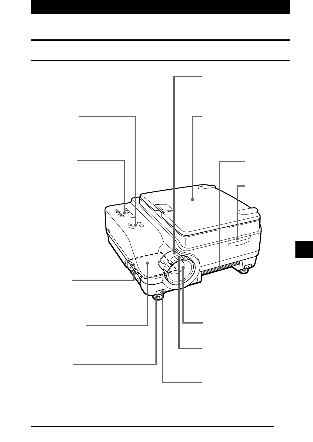
Projector
Part Names and Functions
Zoom adjuster
Rotate to adjust the screen size.
See page E-26 for details.
Adjustment panel
These buttons are provided for setting the
adjustment menu.
See page E-13 for details.
Operation panel
This panel houses the buttons
and indicators used for normal
control of the projector. The
lamp ON/OFF button, input
device switching button, OHP
enlargement button, OHP
brightness button and
indicators are located here.
See page E-12 for details.
Terminal panel
This panel houses the terminals and
connectors for connecting the
projector to a PC, video, or other
device.
See page E-11 for details.
Materials cover
Used for holding down flat materials or
printed matter placed over the scanner.
See page E-29 for details.
Handle
Remote control
sensor
Air vent A (Air filter)
Cool air is drawn in from outside via this vent.
An air filter is provided to prevent dust from
entering the inside of the projector.
See page E-47 for details.
Adjustable feet
Used for adjusting the vertical angle at which
images are projected and the horizontal balance.
Rotate counter clockwise to extend, clockwise to
retract.
See page E-16 for details.
Lens
Images are projected from here.
Focus adjuster
Rotate to adjust the focus.
See page E-27 for details.
Tilt adjust button
Press to adjust the tilt foot.
See page E-16 for details.
E-9
Page 15
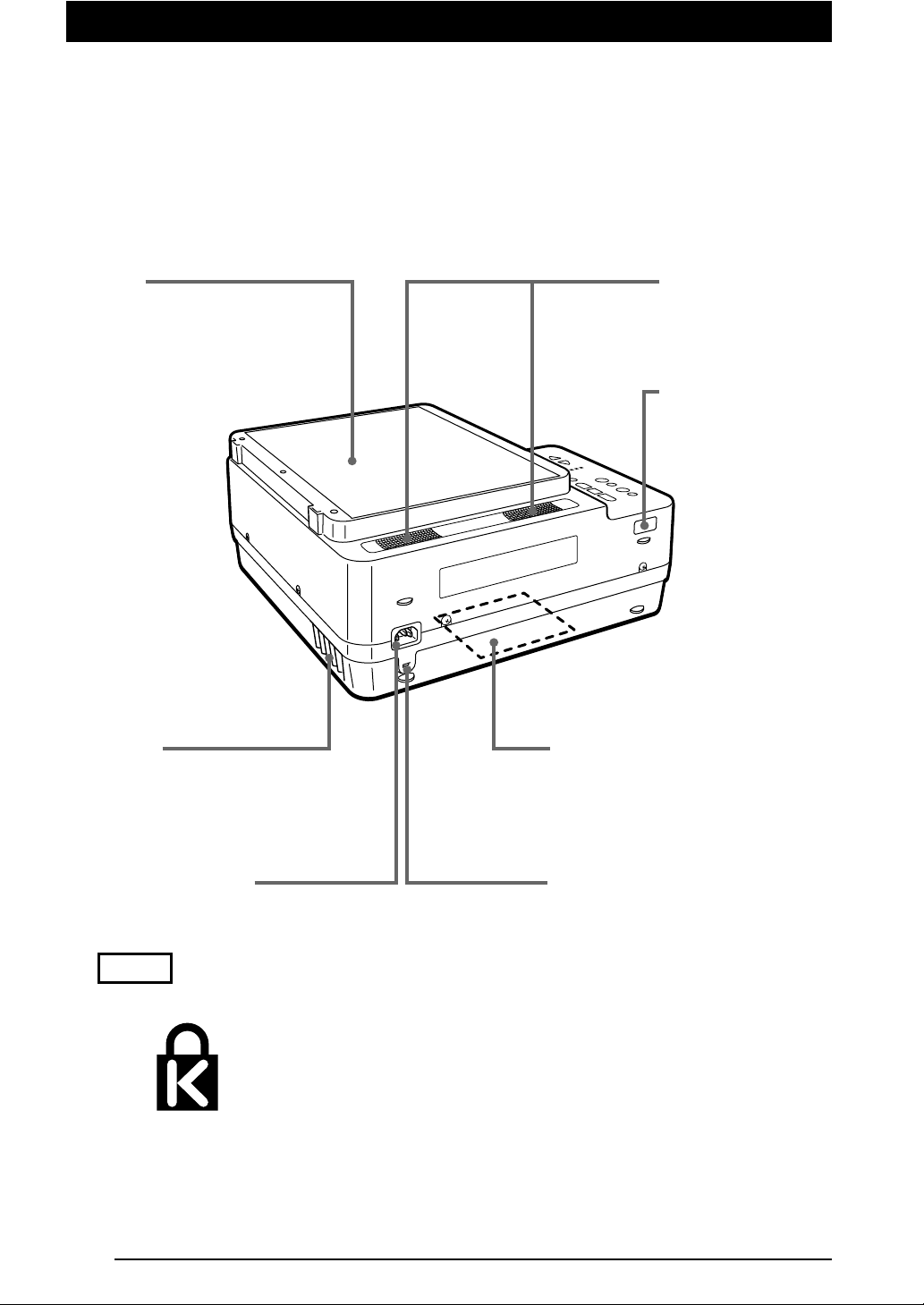
Scanner
Materials or printed matter to be
projected during OHP
presentations are placed on the
scanner.
See page E-29 for details.
Speaker
Remote control
sensor
Air vent B
Air is expelled from this vent.
Power cable connector
See page E-18 for details.
NOTE
•
About the anti-theft lock
E-10
Lamp unit cover (Bottom of the unit)
This cover protects the lamp unit.
See page E-45 for details.
Anti-theft lock
Refer to "NOTE" below.
MicroSaver and Kensington are registered trademarks of Kensington Technology Group. All product names mentioned in this document are trademarks or
registered trademarks of their respective owners.
© 1998 Kensington Technology Group.
Kensington Technology Group
2855 Campus Drive
San Mateo, CA 94403, U.S.A.
Phone:(650)572-2700
Fax:(650)572-9675
Page 16
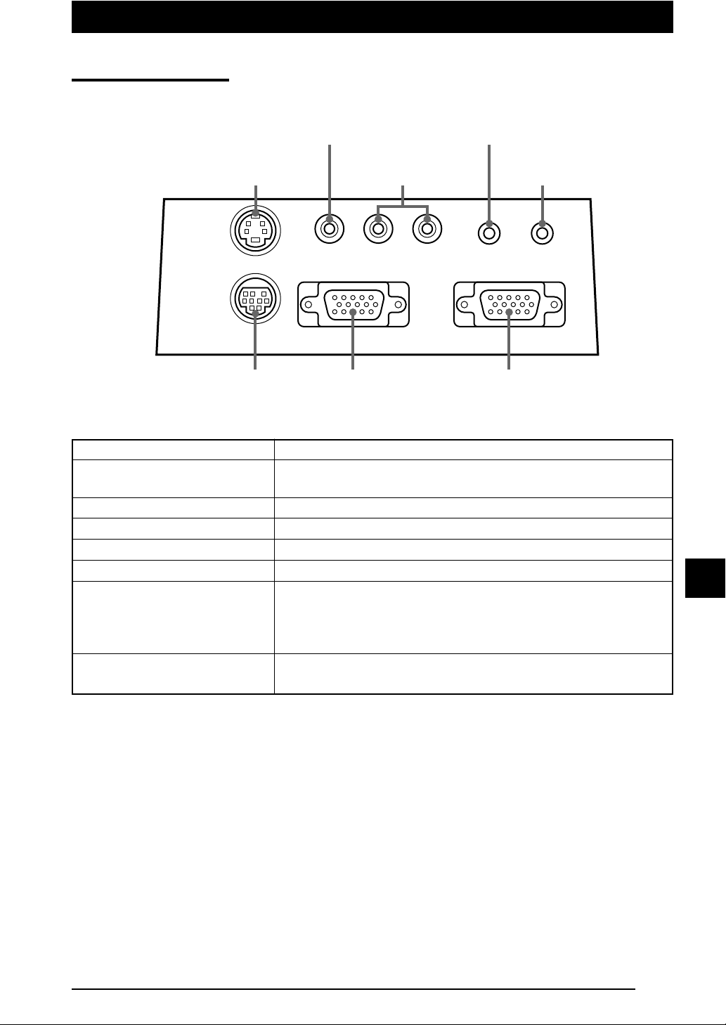
■ Terminal panel
S-video
video input
Video Source
video input
Video Source
audio inputs
Part Names and Functions
Audio output
PC audio
input
S-VIDEO
TEST
Test (maintenance)
input/output
PC video input
PC video output
PC audio input
Video Source audio inputs
Video Source video input
S-video video input
Audio output
Test (maintenance) input/output
RLV OUT IN
PC-OUT PC-IN
PC video
output
PC analog RGB input terminal
Connector for outputting input video images as-is. Video images are
output when the lamp is [ON] or during standby.
PC audio input terminal (stereo).
Video Source audio input terminal (stereo).
Video Source (NTSC, PAL or SECAM) input terminal
S-video (Y/C separation) input terminal
DT100 stereo audio output terminal
This stereo mini-jack outputs the currently selected audio source
(PC or video source). Audio is output from PC during standby.
Audio is output from PC when OHP is selected.
Input/output terminal used only for maintenance and test exclusively.
Service only.
PC-AUDIOVIDEO-IN
PC video
input
E-11
Page 17
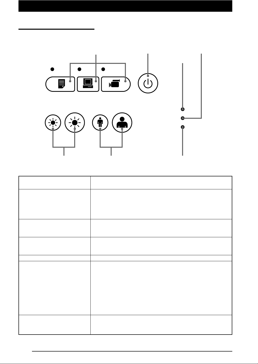
■ Buttons (Operation Panel)
Source selections
(OHP, PC, video source)
ON/STANDBY
Lamp indicator
Power indicator
OHP PC VIDEO
BRIGHTNESS ZOOM
Brightness control
ON/STANDBY button
Source Selections (OHP, PC, and
video source)
Magnification control
(Operates only when OHP is
selected.)
Brightness control
(Operates only when OHP is
selected.)
Power indicator
Lamp indicator
Alarm indicator
ON/STANDBY
POWER
LAMP
ALARM
Magnification control
•Turns the lamp ON/OFF.
• Only this button is operative when the lamp is OFF.
• These buttons select the input device.
• When PC is selected, images from the PC INPUT connector are
projected. When VIDEO is selected, images from the VIDEO input
terminal are projected. When OHP is selected, materials or
printed matter placed on the projector scanner are projected.
• These buttons adjust the OHP magnification. The left button
reduces the image, while the right button enlarges the image.
• These buttons adjust the OHP brightness. The left button makes
the image darker, while the right button makes the image brighter.
• Lights in red during standby and in green when the lamp is lit.
• Lights when the lamp is on
• Blinks for about 6 seconds then stays on when the ON/STANDBY
button is pressed to turn on the lamp.
• Blinks for 120 seconds, then turns off when the ON/STANDBY
button is pressed to turn off the lamp.
• Blinks rapidly if the lamp fails to turn on even when the ON/
STANDBY button is pressed to turn on the lamp.
(In this case, blinks more rapidly than other blinking, and more
slowly when turned off and the lamp fails to turn on.)
• Lights or blinks when machine trouble occurs.
Lit: Indicates overheating
Blinking: Indicates that the fan cover is displaced.
Alarm indicator
E-12
Page 18

■ Buttons (Adjustment Panel)
Part Names and Functions
MENU button
+ / – button
SET button
MENU button
SET button
MENU SET
ADJUST
VOLUME
+ / – button
• This button is used to display the menu screen or to select menus.
Refer to page E-33 and subsequent pages for the contents of
menu setting.
• These buttons call up the menu for the item that you selected by
the MENU button. These are also used to set adjustment parameters.
• These buttons are used to adjust the volume when the menu is
not displayed.
• Press to enter and adjust each menu item.
* The menu screen and adjustment display are automatically turned off and the new settings are stored in memory
after about 15 seconds if no button is pressed.
* See page E-33 for details of menu adjustments.
E-13
Page 19

ON/STANDBY button
s
MENU button
/ / / buttons
Remote Control
ON/
STANDBY
OHP
PC VIDEO
MENU SET
Select buttons
(OHP/PC/VIDEO)
SET button
AUTO SYNC button
KEYSTONE button
ON/STANDBY button
Select buttons (OHP/PC/VIDEO)
MENU button
SET button
/ /t /s buttons
ZOOM buttons
Brightness control buttons
Volume control buttons
AUTO SYNC button
KEY STONE button
AUTO
SYNC
KEYSTONE
ZOOM
BRIGHT
VOLUME
ZOOM buttons
Brightness control button
Volume control buttons
•Turns the projector lamp ON/OFF.
• Only this button is valid when the projector lamp is turned OFF.
• Images from the PC INPUT connector are projected when PC is
selected, images from the VIDEO INPUT when VIDEO is selected, and materials or printed matter placed on the projector are
projected when OHP is selected.
• This button shows the MENU display.
• The same settings as from the operation panel are available using
MENU items.
• Press to fix each menu item.
• Use these buttons to change items, adjust values, or select items
in the MENU display.
Use these buttons to scroll the zoom display in the PC ZOOM display.
•
• These buttons adjust the OHP magnification in the OHP mode.
• Adjusts the magnification of the PC in the PC mode.
The left button reduces the image, while the right button enlarges
the image.
• These buttons adjust the OHP brightness.
The left button makes the image darker, while the right button
makes the image brighter.
•
These buttons adjust the volume in the PC and the VIDEO modes.
The left button turns down the volume, while the right button turns
up the volume.
• This button performs synchronizing automatically. (Valid when PC/
VIDEO is selected.)
• These buttons compensate keystoning.
E-14
Page 20

Part Names and Functions
■ Using Remote Control
• Use the Remote control within about 6 meters (20 feet) and within an angle of 30˚ either
side of a line at right angles to the front or back of the projector. Note that the distance will
diminish as the batteries become exhausted.
• Note that the Remote control will not function if there is any obstacle between it and the
sensor on the projector.
■ Installing Batteries
1. Press and slide the cover off the battery
compartment.
2. Install two batteries in the battery compartment, making sure that they are
aligned as indicated by the (+) and (-)
marks.
3. Slide the cover into position on the
battery compartment.
CAUTION
Handling the Remote control
• Do not subject the Remote control to excessive shock.
• Do not allow water or other liquids to spill onto the Remote control. If they do, wipe dry immediately.
•Avoid heat and humidity. Remove the batteries if the Remote control will be unused for extended periods.
• Do not mix new batteries with old batteries, or batteries of different types.
• Do not disassemble or subject batteries to heat. And do not dispose of batteries in fire.
• Dispose of a used battery according to the local rules.
• The Remote control may not work if an inverter device is near.
NOTE
• Use SUM-3 AA-size batteries.
• Do not use Ni-Cd batteries or rechargeable batteries. Use only manganese batteries or alkaline batteries.
E-15
Page 21

Installation
■ Installation Procedure
Determine the
installation
location and
image size.
"Projection Distance
and Image Size."
Set up a screen
Put your
projector in
place.
Connect
external devices.
PC, video source, etc.See page E-17,
■Adjustable feet
Use the adjustable feet to adjust the position or inclination of the projected image.
Press the right and left tilt adjust button to lift the front side of the unit and let go your hold
when the desired height is reached. Rotate the bottom of the tilt foot for fine adjustment.
Rotate counterclockwise to extend and clockwise to retract the tilt foot.
Tilt adjust button
END
UP
Adjustable feet
CAUTION
• Adjust both feet so that both sides of the front of the projector remain level.
Failure to do so may result in the projector sliding or falling and becoming damaged.
• Air for cooling is forcibly taken in through the air vent A at the bottom of the unit. If the vent is blocked by paper or
cloth, the internal temperature increases, resulting in accidents or malfunctions.
• The rubber feet may soil the floor depending on the materials.
DOWN
E-16
Page 22

■ Projection Distance and Image Size
Use the following diagrams to determine the exact image size and what screen is required
for any given projection distance.
• The focal range is 1.43m (56.3") to 14.86m (585") from the lens. You must install your
projector within this projection distance range.
Width
Screen size
Height
(diagonal)
Installation
(1.43m/56.3 inches to 14.86m/585 inches)
300 610 457
(240" 180")
250 508 381
(200" 150")
200 406 305
(160" 120")
150 305 229
Screen size
(inch) cm (inch)
(120" 90")
100 203 152
(80" 60")
(40" 30")
50 102 76
Width x height
(screen size)
Projection distance
WIDE
3
1
Projection distance
5
TELE
79
11 13 15(m)
CAUTION
Installation location
• Do not install your projector where excessively hot or cold. The ambient temperature should be within the range of
0°C to 35°C (32° to 95°F).
•Position your projector so the sunlight or other bright light source does not strike the screen directly. If sunlight or
other bright light strikes the screen directly, the image will appear white and difficult to see.
If you are using your projector in a brightly lit room, draw the curtains or blinds to darken the area around the
screen.
• Do not install your projector where it will be subject to excessive humidity, dust, soot, or tobacco smoke.
Image quality will deteriorate if dirt builds up on the optical components such as the lenses and mirrors.
• Do not install your projector where the air vents may become obstructed or there is poor air flow. A rise in
temperature may result in fire and damage. (Note that air vents are located at the bottom and on the right side.)
E-17
Page 23

■ Typical Installation
Y
1. Determine where to set up your projector and screen.
Set up your projector on a strong and stable surface that is as level as possible.
2. Connect the supplied power cable and press the
ON/STANDBY
button (or
STANDB
button.)
90°
3. Position your projector so that the screen is at a right angle to the
center line of the projector lens.
Move your projector horizontally so that the top and bottom lines of the image projected
on the screen are straight and parallel to each other.
Adjustable feet
ON/
4. Adjust the adjustable feet to tilt your projector to achieve the desired
projector height. (The tilt can be adjusted from 0° to 7°.)
Adjusting the tilt changes the vertical position of the image projected on the screen.
E-18
Page 24

How to Connect Your Projector
How to Connect Your Projector
CAUTION
•To protect your projector and external input devices, make sure that all power supplies connected to these devices
are turned OFF.
•For details of how to use and connect external input devices to be connected to your projector, refer to the user's
manuals accompanying them.
• Sometimes images are not displayed properly when displaying on notebook PC LCDs. If this happens, turn the
notebook PC display OFF. How to turn the notebook PC display OFF varies according to the manufacturer of the
notebook. For details, refer to the User's Manual provided with the notebook PC.
• Some computers or computers in some settings cannot be connected to your projector. Please consult your
dealer for details.
■ Connecting to a Personal Computer
● List of cables and adaptors
Maker Type
PC/AT
compatibles
Apple
Macintosh
Notebook,
Desktop type
Notebook type
Desktop type
RGB output
Model
Mini D-SUB 15-pin (VGA)
Each maker
PowerBook, G3.
(The monitor output needs to be mini DSUB 15-pin.)
PowerBook
(excluding iBook, DUO, 100, 140,
145B, 150, 170, etc.)
PowerBook DUO
Cannot be connected to models without
*
monitor output such as iBook, PowerBook
100, 140, 145B, 150, 170, etc.
G3, G4 (The monitor output needs to
be mini D-SUB 15-pin.)
Each model (excluding monitorintegrated type)
* The monitor-integrated type such as
iMac, Classic, or certain Performa,
etc. cannot be connected because
they do not have a monitor output.
Connection
Supplied cable
Supplied cable
Adaptor (on the market) *+
Macintosh pin adaptor (on the market)
Supplied cable
Adaptor (on the market) *+
Macintosh pin adaptor (on the market)
Supplied cable
* DUO Dock or Mini Dock is
necessary.
Supplied cable
Adaptor + Supplied cable
* When using the monitor that
comes with the PC, a conversion adaptor for monitor is
necessary.
* The display adaptor (Apple
make) is necessary to Power
Mac 6100.
* Adaptor (on the market): Adaptor for PowerBook exclusively (Apple make: Power Book Video Adapter Cable M3927LL/A or third party make). In
some cases, it comes with the Power Book.
E-19
Page 25

About the PC INPUT and OUTPUT connectors
A 15-pin mini D-SUB connector is used as the PC INPUT and OUTPUT terminals. The
following shows the correspondence between pins and signals.
54321
10 9 8 76
15 14 13 12 11
1 RED VIDEO 6 GND
2 GREEN VIDEO 7 GND
3 BLUE VIDEO 8 GND
4 GND 9 ---5 ----
10
GND
11
12
13
14
15
GND
---H.SYNC
V. SYNC
----
NOTE
• The 15-pin RGB input and output connectors on your projector are for analog signals and cannot be connected to
a PC supporting only a digital signal output.
E-20
Page 26

How to Connect Your Projector
■ If images of a personal computer are not projected
Check the following if images of a personal computer are not projected, or projected incorrectly.
● If images are not projected
If the external output signals from a personal computer are not input to DT100, "No PC
signal" appears on the DT100 display. Check the following if "No PC signal" appears.
1 Restart the computer.
The connection of DT100 may not be recognized by the personal computer, if DT100 is
connected after the PC is started up. If the connection is not recognized, images are not
projected because no external output signals from the PC are output.
2 Check the functions of the personal computer.
Some notebook PCs require a special operation to output the signals from the external
output terminal. The external output signals may not be output from the notebook PC
unless the operation is performed.
Refer to the manuals of your notebook PC for the information about how to output signals
from the external output terminal.
Procedure example
• In the case of IBM PC/AT
PressFnkey and one of the keysF1to models.)
F12
. (Procedure may vary from models
List of countermeasures when the connection with the PC is defective
Maker Series
IBM Think Pad Fn+f7
COMPAQ CONTURA
ARMADA
DELL
* This list is compiled based on the troubles that have occurred so far, so it does not include all kinds of
connections.
* The company names, product names are the trade marks or registered trade marks of each company.
LATITUDE
Method to switch
to external output
Fn+f4
Fn+f8
● Images are not projected correctly though they are displayed normally
on the notebook PC.
1 Check the function of the notebook PC.
There is a possibility that images are not projected correctly even through the images are
displayed correctly on the LCD of the notebook PC. When images are displayed on two or
more devices at the same time (e.g. images on the LCD and the signals are output to
other devices at the same time), the input signals are outside the scanning frequency
range of DT100 because of the restrictions on the notebook PC.
In this case, the correct images cannot be obtained even by the adjustment of DT100.
Te r minating the display on the LCD, so that only the external output signals are output,
may project images correctly on DT100. Refer to the manuals of your notebook PC for
details.
E-21
Page 27

■ Input Signal Compatibility Table (PC video input)
Signals marks by ● are compatible on the DT100. If there is a flicker or blur in the projected
screen depending on PC model, adjust the screen using the "Sync adjustment" menu.
Signal
NTSC RGB - - 15.7 60 ✕
PAL/SECAM RGB - - 15.6 50 ✕
VGA-GR1 640 480 31.5 60 ●
VGA-GR2 640 400 31.5 70 ●
VGA-GR3 640 350 31.5 70 ●
VGA-TX 1 720 400 31.5 70 ●
VGA-TX2 720 350 31.5 70 ●
640✕480 72Hz 640 480 37.8 72 ●
640✕480 75Hz 640 480 37.5 75 ●
640✕480 85Hz 640 480 43.2 85 ●
Mac13"RGB 640 480 35.0 66 ●
800✕600 56Hz 800 600 35.1 56 ●
800✕600 60Hz 800 600 37.8 60 ●
800✕600 72Hz 800 600 48.0 72 ●
800✕600 75Hz 800 600 46.8 75 ●
Mac16"RGB 832 624 49.7 74 ●
1024✕768 43Hz 1024 768 35.5 43 ✕
1024✕768 60Hz 1024 768 48.3 60 ●
1024✕768 70Hz 1024 768 56.4 70 ●
1024✕768 75Hz 1024 768 60.0 75 ●
1024✕768 85Hz 1024 768 68.7 85 ●
MAC19"1024✕768 1024 768 60.2 75 ●
MAC21"1152✕864 1152 864 68.7 75 ●
1280✕960 60Hz 1280 960 60.0 60 ●
1280✕960 85Hz 1280 960 85.9 85 ●
1280✕1024 60Hz 1280 1024 64.0 60 ●
1280✕1024 75Hz 1280 1024 80.0 75 ●
1280✕1024 85Hz 1280 1024 91.1 85 ●
1600✕1200 60Hz 1600 1200 75.0 60 ✕
1600✕1200 65Hz 1600 1200 81.3 65 ✕
1600✕1200 70Hz 1600 1200 87.5 70 ✕
1600✕1200 75Hz 1600 1200 93.8 75 ✕
1600✕1200 85Hz 1600 1200 106.3 85 ✕
Resolution
(Horizontal ✕ Ver tical) (kHz) (Hz)
Horizontal Frequency
Ver tical Frequency
Compatibility
* When the resolution of input signal is 1024 X 768 dots or lower, the display is enlarged, and when more
than 1024 X 768 dots, it is reduced.
E-22
Page 28

● Typical Connection Examples
DT100 terminal panel
How to Connect Your Projector
S-VIDEO
TEST
Insert the connector and tighten the screws.
The type of connector cable varies
according to the type of PC.
To RGB input connector
of monitor
● IBM Notebook Models and Compatible
IBM PC/AT and compatibles
Signal cable
(supplied)
RLV OUT IN
PC-AUDIOVIDEO-IN
PC-OUT PC-IN
To analog RGB
outputs of PC
To PC-IN
connector
To Audio
outputs of PC
To speaker
input
NOTE
Connect the Supplied signal cable, then use the PC's software to check the external CRT output and internal LCD
output status and select the correct mode.
Unless in external CRT output mode, no signal will be output.
● IBM Desktop Models and Compatible
IBM PC/AT and compatibles
Monitor cable
To PC-OUT
connector
To PC-IN
Signal cable
(supplied)
NOTE
Connect only the Supplied signal cable if you are connecting the PC directly to your projector without using the
PC's monitor.
connector
DT100
DT100
E-23
Page 29

● Apple Macintosh Notebook Models and Compatible
Excluding PowerBook Duo, 100, 140, 145B, 150, and 170
PowerBook
display adptor
Macintosh pin adaptor
(not supplied)
Signal cable
(supplied)
To PC-IN
connector
NOTE
• The Duo Dock or Mini Dock is required for the PowerBook Duo.
• The PowerBook display adapter is supplied only with some PowerBook models. If not supplied, please purchase
one from your Macintosh dealer.
(Apple M3927LL / A or the equivalent)
● Apple Macintosh Desktop Models and Compatible
Monitor cable
Macintosh pin adaptor
(not supplied)
Signal cable
(supplied)
Adaptor
(not supplied)
To PC-OUT
connector
To PC-IN
connector
DT100
DT100
NOTE
• The Power Mac display adaptor (M2681LL/A) is required with the Power Mac 6100.
• Cannot be connected to iMac or iBook.
E-24
Page 30

How to Connect Your Projector
■ Connecting to a Video Source (VCR, DVD or Laser Disc)
Images from a VCR, DVD or laser disc players can be projected on-screen by your
projector.
or
Laser disc player
To video output terminal To audio output terminals
S-VIDEO
TEST
PC-OUT PC-IN
Video deck
RLV OUT IN
PC-AUDIOVIDEO-IN
DT100 terminal panel
NOTE
• If you connect both video and S-video cables, the S-video input takes precedence.
• When you use a video source or laser disc player, be sure to close the materials cover. (If it is not closed, the
glass over the scanner may vibrate and generate chattering noises.)
E-25
Page 31

Operation
■ Basic Operation of Input Devices PC and Video Source
Preparation
:Turn on the power of PC or video source.
2, 5, 6, 7
1
1 Connect the power cable.
The unit enters the standby mode and the POWER indicator
lights in red.
If the LAMP indicator blinks in red, the lamp is defective.
POWER
LAMP
ALARM
Press the ON/STANDBY button.
The lamp lights and the POWER indicator lights in green.
The LAMP indicator lights in green.
2 Select the external input device.
Main control
OHP PC VIDEO
Press the button for the desired input device (OHP, PC, or
video source).
3
4
The screen changes to the display for the desired input device.
Remote control
PC, video source
OHP PC VIDEO
Start operating the
connected device.
NOTE
When you select PC or video source as the input device, the blue back is displayed and "No PC signal/No
VIDEO signal" appears in the following instances:
• when the selected input device has not been connected;
• when the selected input device is not turned on.
3 Adjust the zoom.
Rotate the zoom adjusting ring to adjust the screen size.
E-26
OHP
See page E-29 for
details.
Page 32

4 Adjust the focus.
Rotate the lens focusing ring until a sharp image is projected
on the screen.
Operation
5 Compensating keystoning
6 Adjusting PC zoom
7 Adjusting volume
Main control
KEYSTONE
Remote control
ZOOM
Remote control
VOLUME
Refer to “Compensating keystoning” on page E-32.
Refer to “PC zoom” on page E-31.
E-27
Page 33

When You Have Finished Using Your Projector
9
8
8 Turn off the lamp.
Main control
ON/STANDBY
Press the ON/STANDBY button.
“Press ON/STANDBY switch again to turn off” appears on the
projected image.
Remote control
Press the ON/STANDBY button again.
ON/
STANDBY
NOTE
If you press the ON/STANDBY button while the LAMP indicator is blinking in green, the lamp lights again.
If you press it again, the unit enters the standby mode.
9 Pull out the power cable.
POWER
LAMP
ALARM
The LAMP indicator blinks in green and turns off in two
minutes.
The POWER indicator turns on in red.
The POWER indicator on the operation panel goes out.
CAUTION
• Do not pull out the power cable from the power outlet before turning off the lamp or the LAMP indicator
turns off. Doing so may shorten the useable life of the lamp.
• If you are not going to use your projector for an extended period, disconnect the power cable from the power
outlet.
•Wait a predetermined time (about 10 seconds) before you turn the power on after turning it off.
NOTE
• Due to its characteristics, the lamp may not light if it is turned on immediately after having been turned
off. Wait one minute or more and turn it on again.
• The lamp may sometimes emits a slight humming sound when on. This is normal.
E-28
Page 34

■ Basic Operation in the OHP Mode
The functions described here can only be used when your projector is set for OHP use.
Operation
1
NOTE
• In the case of the OHP projection (material projection), there may be distortion more or less because an
ultra-wide lens is used.
2, 3, 4
1 Open the scanner cover and place the materi-
als to be projected on the scanner.
Close the cover.
NOTE
• Though materials can be projected without closing the materials cover, unwanted light, etc., may enter the
scanner, making the projected image more difficult to view.
2 Select the magnification.
Main control
ZOOM
You can adjust the magnification between 100% and 200%.
Press the left button to reduce the magnification or the right
button to increase the magnification.
Remote control
ZOOM
NOTE
The brightness will change slightly if you alter the magnification.
3 Adjust the brightness.
Main control
BRIGHTNESS
To darken the image, press the button on the left. Conversely,
to lighten the image, press the button on the right.
Remote control
BRIGHT
NOTE
• When the materials or printed matter are nearly black, adjust the brightness to increase, and when they are
nearly white, adjust it to decrease.
E-29
Page 35

4 Compensating keystoning.
Remote control
Refer to “Compensating keystoning” on page E-32.
KEYSTONE
Document Direction and Scan Size
Place materials or printed matter in the following direction.
The maximum scan size of materials or printed matter is 216 mm/8.5" (vertical) by 288 mm/
11.3" (horizontal). When an A4-size document is placed in the projector, the scan sizes are as
follows (the shaded section shows the area of the materials that is projected, or the "scan
area".)
*1 If you align the paper with the material scan line, it is easy to align with the center.
A4-size paper (landscape)
297mm/11.7" (paper size)
288mm/11.3" (scan size)
216mm (scan size)
210mm (paper size)
The area outside the scan area is not
projected on the screen. To project this area,
shift the paper.
A4-size paper (portrait)
288mm/11.3" (scan size)
210mm/8.3" (paper size)
216mm (scan size)
297mm (paper size)
*1
When A4-size (portrait) materials are placed
on the scanner, the screen can be effectively
used by increasing the magnification.
E-30
Page 36

■ PC Zoom
This function is valid only for PCs.
The zoom function can be executed by the remote control.
Operation
1 Select the external input device.
Main control
OHP PC VIDEO
Press the PC (Personal Computer) button for the input device.
The display of the PC input image appears.
*You can select the external input device by DT100 and
Remote Control.
Remote control
OHP PC VIDEO
2 Select the magnification.
Remote control
ZOOM
You can select the magnification using by the ZOOM buttons
on the remote control.
Press the
Press the
*You can adjust the zoom (magnification) arbitrarily up to x4
(four times).
button to increase the magnification up to x4.
button to return the magnification to x1.
3 Move the zooming area.
Remote control
You can move the zooming area by using arrow buttons on the
remote control.
button : moves upwards
button : moves downwards
button : moves to the left.
button : moves to the right.
In the zooming area, some blanks may appear on the above,
below, to the left or to the right of the input PC signals.
E-31
Page 37

■ Compensating Keystoning
After compensating keystoning, the resolution at the top (or bottom) of the image is deteriorated and the small characters are hard to read. To prevent this, place the projector on a
base as even as possible and set "Keystone" of the "Setting" menu to "0". (Refer to "Making
Adjustment" on page E-33 for the information about how to set.)
● How to Compensate Keystoning
EX.1
Press the KEYSTONE button of the remote control to narrow the lower part of the
image.
EX.2
Press the KEYSTONE button of the remote control to narrow the upper part of the
image.
NOTE
• Since the keystoning compensation relates to the image processing, the displayed images (or characters) are
more or less obscure compared to when the keystoning compensation is not used.
E-32
Page 38

■ Making Adjustment
Menu Structure
Use buttons to show the menu display on the projected screen for various adjustments and
settings. To show the main menu display, connect PC or video source, and press the
button (or
The transition diagram of the menu display is shown below.
MENU
MENU
(or )
<When PC is selected for an input device>
MENU
button) with the power turned on. Select each submenu from the main menu.
MENU
Main menu Menu
Image adjustment
Contrast
0
0
Brightness
0
Red
0
Blue
Standard Quit
Image adjustment
Gamma
Red
Blue
Standard
0
0
/
PHOTO TEXT
Appears when
OHP is selected.
Quit
Volume
Image adjustment
Sync adjustment
Setting
MENU
Language selection
Projection mode
Memory
Quit
MENU
(or )
Operation
MENU
MENU
Volume
Image adjustment
Video adjustment
Setting
Language selection
Projection mode
Video select
Quit
<When video source is selected for an
input device>
Image adjustment
<
When OHP is selected
MENU
Language selection
Setting Projection mode
Quit
>
Sync adjustment
50
Clock
50
Phase
9
Horizontal
15
Vertical
Standard Quit
Setting
Input signal
1024 X 768 60Hz48.2KHz
Lamp usage time
Keystone
Auto power off
Start up screen
Standard
Tint
Color
Sharpness
Standard
English
Deutsch
Français
Italiano
0H
0
ON OFF
ON OFF
Memory
Save
Load
Quit
Video adjustment
0
R
R
0
R
0
Volume
Language selection
Projection mode
Floor
Rear
Quit
/
/
Quit
Española
Svenska
日本語
Appears only
when PC is
selected as
an input device.
Quit
Appears only
when PC is
selected as
an input device.
Appears only
when video
G
G
G
source is selected
as an input device.
Quit
Quit
AUTO
PAL B ,G,H,I
NTSC3.58
SECAM
NTSC4.43
Video select
PAL M
PAL N
PAL 6 0
Appears only
when video
source is selected
as an input device.
Quit
E-33
Page 39

Description of Menu Items
Each menu display and items and functions to be set are described. Refer to "Basic Operation" on page E-37 for information about setting.
◆ Image adjustment
Image adjustment
Contrast
Brightness
Red
Blue
Standard Quit
0
0
0
0
Menu item
Contrast
Brightness
Red
Blue
<Image adjustment menu>
◆ Image adjustment (when OHP is selected)
Image adjustment
Gamma
Red
Blue
Standard
0
0
/
PHOTO TEXT
Quit
<Image adjustment menu>
Menu item
Gamma
Red
Blue
Adjust the contrast of the projected screen.
Adjust the brightness of the projected screen.
Change the depth of red.
Change the depth of blue.
Setting
PHOTO/TEXT
-100 to +100
-100 to +100
Description
Description
"TEXT" is adjusted according to
text materials and "PHOTO", to
photo materials. Select as you like.
Change the depth of red.
Change the depth of blue.
◆ Sync adjustment (Only when PC is selected as an input device)
Sync adjustment
Clock
Phase
Horizontal
Ver tical
Standard Quit
0
0
9
15
<Sync adjustment menu>
Menu item
Clock
Phase
Horizontal
Vertical
Setting
-100 to +100
-100 to +100
–82 to +100
–70 to +100
Description
Adjust the horizontal size of the
image.
Adjust noises and flicker.
Adjust the position of the image
horizontally.
Adjust the position of the image
vertically.
◆ Setting
Input signal
Lamp usage time
Keystone
Auto power off
Start-up display
Standard
1024 X 768 60Hz48.2KHz
Setting
0
0H
/
ON OFF
/
ON OFF
Quit
Menu item
Keystone
Auto power off
<Setting menu>
Start-up display
NOTE
• In the [Setting] menu, the input signals currently set and the accumulated used time of the lamp appears for your
confirmation.
Setting
-100 to +100
ON/OFF
ON/OFF
Description
Compensate keystoning.
Set the auto power off to ON or
OFF. When Auto power off is set to
ON, the unit enters the standby
mode automatically when no signal
arrives for a predetermined time
(about 15 minites).
Set the logo display to appear or
not when the lamp turns on.
E-34
Page 40

Operation
◆ Video adjustment (Only when video source is selected as an input device)
Video adjustment
Tint
Color
Sharpness
Standard
0
R
R
0
R
0
Quit
<Video adjustment menu>
Menu item
Tint
G
G
G
Color
Sharpness
Setting
-100 to +100
-100 to +100
0 ~ 6
Description
Change the depth of color.
Change the hue.
Change the clarity of the image.
◆ Memory (Only when PC is selected as an input device)
Memory
Save
Load
Quit
<Memory menu>
Menu item
Save
Load
Setting
–
–
Description
Save the contents set in the Sync
adjustment menu.
Load the saved contents.
◆ Volume
Volume
0 100
Quit
Menu item
Volume
Setting
0 to 100
Description
Change the volume.
<Volume menu>
◆ Language selection
Language selection
English
Deutsch
Français
Italiano
<Language selection menu>
Española
Svenska
日本語
Quit
Menu item
Language
selection
Setting
English
Deutsch
Français
Italiano
Española
Svenska
Description
Change the language used in
display.
E-35
Page 41

◆ Projection mode
Projection mode
Floor
Rear
Quit
<Projection mode menu>
Menu item
Projection
mode
Floor
Rear
Setting
Description
Select according to the setting
type of the front or back projection.
◆ Video select (Only when video source is selected as an input device)
Video select
AUTO
PAL B,G,H,I
NTSC 3.58
SECAM
NTSC 4.43
PAL M
PAL N
PAL 6 0
<Video select menu>
Menu item
Video select
Quit
Setting
AUTO
PAL B,G,H,I
NTSC3.58
SECAM
NTSC4.43
PAL M
PAL N
PAL 60
Description
Select input video signals.
E-36
Page 42

■ Basic Operation
MENU
MENU
The basic operation of each menu, “Image adjustment”, “Sync adjustment”, “Setting”, “Video
adjustment”, “Volume”, “Language selection”, “Projection mode”, and “Video select” is
described. Refer to E-41 page about the operation of the "Memory" menu.
Operation
Main control
1,2
MENU SET
ADJUST
VOLUME
Remote control
1
ON/
STANDBY
OHP
PC VIDEO
1 Press the
The main menu appears.
Image adjustment
Sync adjustment
<When PC is selected as an input device>
2 Press the
select an item for setting.
Volume
Setting
Volume
button (or
MENU
MENU
button).
Language selection
Projection mode
Memory
Quit
button (or buttons) to
MENU
Language selection
MENU SET
AUTO
SYNC
KEYSTONE
2
ZOOM
BRIGHT
VOLUME
Image adjustment
Sync adjustment
Setting
<When “Sync adjustment” is selected.>
Projection mode
Memory
Quit
E-37
Page 43

MENU
4-1
MENU SET
Main control
3
3 Press the
The menu display of the item selected for setting.
In the "Image adjustment", "Sync adjustment", "Setting" or
"Video adjustment" menu, select “Standard” and press the
SET
button (or
initial state at purchase.
SET
button (or
SET
button) to return the setting to the
Sync adjustment
SET
button).
ADJUST
VOLUME
Remote control
ON/
STANDBY
OHP
PC VIDEO
MENU SET
3
Clock
Phase
Horizontal
Vertical
Standard Quit
0
0
9
15
<Sync adjustment Menu>
When selecting “ON” or “OFF”.
The menu items required for selection of “ON” or “OFF” are
“Auto power off” and “Start up screen”. See page E-34 for
the detail of each menu item.
4-1 Press the
select an item for setting.
button (or buttons) to
Setting
E-38
AUTO
SYNC
KEYSTONE
ZOOM
BRIGHT
VOLUME
4-1
Input signal
Lamp usage time
Keystone
Auto power off
Start up screen
Standard
1024 X 768 60Hz48.2KHz
0
<When “Auto power off” is selected.>
0H
/
ON OFF
/
ON OFF
Quit
Page 44

Operation
MENU
Main control
4-1
MENU SET
4-2
Remote control
ADJUST
VOLUME
4-2 Press the buttons (or buttons )
to select “ON” or “OFF”.
Setting
Input signal
Lamp usage time
Keystone
Auto power off
Start up screen
Standard
1024 X 768 60Hz48.2KHz
0H
0
/
ON OFF
/
ON OFF
Quit
When adjusting in units of point
The menu items required to be adjusted in units of point
are “Contrast”, “Brightness”, “Red”, “Blue”, “Clock”, “Phase”,
“Horizontal”, “Vertical”, “Keystone”, “Tint”, “Color”, “Sharpness”, and “Volume”. See page E-34 for the detail of each
menu item.
4-1 Press the
button (or buttons) to
ON/
STANDBY
OHP
MENU SET
AUTO
SYNC
KEYSTONE
4-2
PC VIDEO
ZOOM
BRIGHT
VOLUME
4-1
select an item for setting.
Sync adjustment
Clock
Phase
Horizontal
Vertical
Standard Quit
<When “Clock” is selected.>
0
0
9
15
E-39
Page 45

Main control
MENU
MENU
4-2 Press the buttons (or buttons )
to adjust.
Sync adjustment
4-1, 5
MENU SET
4-2
Remote control
ON/
STANDBY
OHP
ADJUST
VOLUME
PC VIDEO
5
5
Clock
Phase
Horizontal
Vertical
Standard Quit
0
0
9
15
Others
Other menu items include “Language selection”, “Projection
mode”, and “Video select”. See page E-34 for the detail of
each menu.
4-1 Press the
select an item for setting.
English
button (or buttons) to
Language selection
Española
E-40
MENU SET
AUTO
SYNC
KEYSTONE
4-2
ZOOM
BRIGHT
VOLUME
4-1, 5
Deutsch
Français
Italiano
<When “English” is selected from the “Language selection” menu.>
5 Press the
select “Quit” and press the
SET
button).
The display returns to the main menu display. If there is no
button operation for 15 seconds, the display goes off
automatically and the adjusted value is memorizes.
Svenska
日本語
Quit
button (or buttons) to
SET
button (or
Page 46

Operation
■ About the "Memory" menu
When PC is selected as an input device and you make an adjustment for the size of an image,
noises and flicker, or the vertical/horizontal positions, you can save the contents of the adjustment. You can then call up the saved contents of the setting.
● Saving
1 Adjust the image display in the "Sync adjustment" menu. (page E-34)
2 Select "Memory" in the main menu.
Memory
Save
Load
Quit
3 Select "Save".
MENU
button (or / buttons) to
0 x 0
0 x 0
0 x 0
0 x 0
0 x 0
Save
0 Hz
0 Hz
0 Hz
0 Hz
0 Hz
Quit
Press the
select an item to save.
You can select up to five items.
The message "Save ?" appears as below and if you select [YES], the selected items are
saved and the menu goes off automatically.
0 x 0
0 x 0
0 x 0
0 x 0
0 x 0
Save
Save ?
YES /
0 Hz
0 Hz
N O
0 Hz
0 Hz
Quit
If you select [NO], the selection is canceled
and the menu goes off automatically.
E-41
Page 47

● Loading
1 Select "Memory" in the main menu.
Memory
Save
Load
Quit
2 Select "Load".
Load
0 x 0
1280 x 720
1024 x 768
0 x 0
0 x 0
0 Hz
60
60
0 Hz
0 Hz
Hz
Hz
Quit
Press the
MENU
button (or / buttons) to
select data to load.
Select an item to which the saved data is
registered.
The message "Load ?" appears as below and if you select [YES], the selected item is
loaded and the menu goes off automatically.
Load
0 x 0
1280 x 720 60
1024 x 768
0 x 0
0 x 0
Load ?
0 Hz
Hz
YES /
0 Hz
0 Hz
N O
Quit
NOTE
• Even while being selected, if the input signal changes, the selected signal is canceled and the signal judge is
switched to automatic extraction.
If you select [NO], the selection is canceled
and the menu goes off automatically.
E-42
Page 48

Maintenance
■ Protection from Overheating
Your projector is provided with internal protection circuits for preventing fire and damage to
internal components caused by abnormal temperature rises inside.
When the ALARM indicator is blinking:
● Action
1. Pull out the power plug from the power outlet.
2. Install the air filter correctly.
* If the LAMP indicator is also blinking, replace the lamp unit a new one.
(See page E-42, "Replacing the Lamp unit.")
When the ALARM indicator is lit:
● Action
1. Pull out the power plug from the power outlet.
2. Check the following and take the necessary steps to alleviate the problem.
Maintenance
Ambient temperature is
more than 35°C/95°F.
Vent holes are blocked.
Air filter is clogged.
Problem in internal circuitry.
* When the ALARM indicator is out, your projector is working correctly.
Place your projector in an area
having an ambient temperature of 0°C/32°F to 35°C/95°F.
Place your projector well clear
of surrounding objects such as walls, etc.
Refer to "Do not block the air vents" on page E-4.
Clean the air filter.
Refer to "Cleaning the Air filter" on page E-47.
Call qualified service personnel.
E-43
Page 49

● When the Power Supply Stops (All Indicators Remain OFF When Power Switch is ON)
❍ Action
1. Pull out the power plug from the power outlet.
2. Check the following and take the necessary steps to alleviate the problem.
Ambient temperature is
more than 35°C/95°F.
Vent holes are blocked.
Lamp unit cover is not
securely in place.
Problem in internal circuitry.
Place your projector in an area having
an ambient temperature of 0°C/32°F to 35°C/95°F.
Place your projector well clear of
surrounding objects such as walls, etc.
Refer to "Do not block the air vents" on page E-4.
Install the cover securely.
Refer to "Replacing the Lamp unit" on page E-45.
Call qualified service personnel.
E-44
Page 50

■Replacing the Lamp unit
The life of the lamp used on this projector is 1400 hours.(This may shorten due to the
conditions of use.)
The lamp is designed to forcibly turn off in the case of a lamp possibly breaking if it is used
beyond the lamp usage of 1500 hours.
When the lamp is used for 1400 hour or more, replace the entire lamp unit (sold separately)
in the following instances. When the projected image becomes dark or projected colors are
unsatisfactory, the lamp has reached the end of its life. When this happens, replace the
entire lamp unit.
● When images are displayed as follows when the lamp is lit: (This appears when the lamp
is used for 1400 hours or more.)
Lamp usage 1400 hours.
Replace the lamp.
● When the Lamp usage time (total lamp usage time) in the menu screen reaches 1400
hours : The LAMP indicator blinks.
You can check the lamp used time, which is displayed in the "Setting" menu. (Refer to
page E-34.)
Maintenance
● When the lamp does not light, and the LAMP indicator is blinking : (When the lamp is
used for 1500 hours or more.)
POWER
LAMP
ALARM
WARNING
• Do not replace the lamp unit immediately after using your projector.
The lamp becomes very hot and you may burn yourself. Disconnect the power cable from the power outlet, then
allow the unit to cool for at least one hour.
• Do not touch the lamp with the hand. Touching the lamp in this way results in reduced brightness or reduced lamp
life.
• This projector uses many glass components (e.g. lamp and mirrors). If these glass components break, handle
them with care to prevent personal injury from glass fragments. Then, contact your dealer for repair.
NOTE
•
Specify the lamp unit DT01LP.
To replace the lamp unit, follow the procedure below.
1 Remove the lamp unit cover.
Loosen the screw holding the lamp unit cover using a
Phillips blade screwdriver.
E-45
Page 51

2 Loosen the lamp screws.
Loosen the screws of the lamp unit.
3 Remove the lamp unit.
Grasp the lamp unit handle and lift it out of the housing.
4 Install a new lamp unit.
q Push the lamp unit inside while holding the handle.
w Check that the three protrusions for position making
are inserted securely in the three holes.
e Tighten the lamp unit cover fixing screws.
r Install the lamp unit cover and tighten the lamp unit
cover fixing screw.
Be sure to tighten the screws.
OHP PC VIDEO
MENU
5 Reset the lamp usage time.
While pressing the
PC
the
button and the
MENU
button, press the
OHP
button one after one.
VIDEO
Then the LAMP indicator blinks.
Input signal
Lamp usage time
Keystone
Auto power off
Start up screen
1024 X 768 60Hz48.2KHz
Standard
Setting
0
0H
/
ON OFF
/
ON OFF
1
2
3
Quit
CAUTION
Do not reset the lamp usage time without replacing the lamp.
There is a high possibility that it breaks if it is used beyond
the lamp life of 1500 hours of use.
6 Make sure that the Lamp usage time is
"0H" as shown in the figure on the left.
If the lamp usage time has not been reset, repeat step
5 to reset the time.
CAUTION
Be sure to reset the lamp usage time after replacing the
lamp.
You will no longer be able to tell how long the lamp has been
used if the new lamp is used without resetting the lamp usage
time.
When the display exceeds 1500 hours, the power of the lamp
is turned off forcibly regardless of the life of the lamp.
NOTE
•
As a safety interlock, your projector lamp does not turn on unless the lamp unit cover is installed.
•
The lamp unit is sold with the air filter as a set. Therefore, replace the air filter at the same time as replacing the
lamp unit. (See page E-47.)
button ,
E-46
Page 52

Maintenance
■ Cleaning the Air filter
The air filter keeps the optical components of your projector free from dust and dirt. Dust or
dirt on the air filter can cause heat to build up inside your projector, resulting in the increase
of the fan speed. This, in turn, may reduce lamp life or result in damage to internal
components. The filter should therefore be cleaned regularly (approximately once a month if
the projector is used for about four hours a day.)
If it is difficult to remove the dust and dirt from the air filter, replace with a new air filter kit.
To clean the air filter, follow the procedure below.
1 Remove the air filter panel.
While pressing the knob of the air filter, lift and remove
the air filter.
2 Clean off the dust.
Use a vacuum cleaner to clean off dust from the outside
(protruding surface) of the air filter.
3 Re-attach the air filter.
Attach the air filter following the above procedure in
reverse.
CAUTION
Caring for the Air Filter
• Do not clean the air filter with water or other liquid. This can block the filter.
• Do not wipe with a cloth or wet rag as this, too, can block the filter.
• Always clean off dust from the outside (protruding surface) of the air filter. If you clean off the dust from the inside,
this will reduce the effectiveness of the filter.
• Do not forget to re-attach the air filter. Using your projector without an air filter may result in dust and dirt impairing
the projected image.
• Always replace damaged air filters with a new air filter kit (sold separately). If you use your projector with a
damaged air filter, dirt or dust will enter inside, impairing the projected image.
NOTE
The projector lamp will not light up if no air filter is installed.
E-47
Page 53
Troubleshooting
If you think a fault has occurred, check the following table and take the required action.
Problem
Projector does not turn on E-18
The projector lamp does not light. E-45
No picture E-26
Picture is distorted. E-18
Picture is blurred E-27
Image jitter E-34
Picture shifts. E-34
Color shift E-34
No sound E-35
Cabinet emits cracking sound
Alarm indicator is lit or blinking. E-43
Remote control does not operate.
• The power cable is disconnected.
• The lamp unit cover has not been replaced.
• The lamp is blown.
• The air filter has not been replaced.
• The temperature inside your projector is too high. For protection, the
lamp does not light.
• The lamp usage time has exceeded 1500 hours.
• Selected input device is not connected.
• Cable from input device not connected correctly.
• "Brightness" or "Contrast" in the "Image adjustment" menu is set
fully to the negative side.
• Check the functions of the personal computer.
•Your projector is not positioned correctly.
• The keystoning is set.
•Focus not adjusted.
• The projection distance should be within the limit of the lens' focal
range.
• The keystoning is set.
• Adjust the PHASE under "Sync adjustment" menu.
• Press the
adjustment".
• Is the setting in the "Sync adjustment" menu correct?
• Adjust the PHASE under "Sync adjustment" menu.
• The volume control is set fully to the negative side.
•Cracking sounds are emitted when the cabinet expands or shrinks
slightly due to changes in temperature. These sounds do not affect
performance.
• Follow the procedure described in Protection from Overheating.
• The air filter is missing.
• Batteries exhausted or worn out.
• The remote control sensor is radiated by other lights such as
lighting.
• The remote control sensor on your projector is obscured.
•Inverter equipment is near.
AUTO
SYNC
button of the remote control and perform "Sync
Check These items
See Page
E-45
E-47
E-43
E-45
E-19, E-25
E-34
E-21
E-32
E-17
E-32
E-14
-
E-47
E-15
E-9, E-10
E-9, E-10
E-15
E-48
Page 54

Specifications
Troubleshooting
Model Number
Optical
LCD panel Size
Drive method
Number of pixels
Arrangement
Lens
Lamp
Image size / Projection Distance
Electrical
Color reproduction
Scanning frequency
Display of available resolution (RGB signal input)
OHP Scanner
Scan speed
Scan size
PC Signal system
(Analog Video signals
RGB Input
Video I/O
Video Signal system
Monitor Video signal
output
PC Audio signal
Video Input terminal
Monitor Audio signal
Audio input
output Output terminal
Audio output
Ambient temperature and humidity
Storage temperature and humidity
Power requirement
Mechanical
External dimensions
Weight
Accessories
Regulations
) Synchronizing
signals
Input terminal
Input terminals
Synchronizing signals
Output connector
1.3-in.(3 panels) Aspect ratio 4:3
Polysilicon TFT active matrix with micro lens array
786,432 pixels (1,024 dots x 768 dots) x3
Stripe
Manual zoom X1-1.3, f=49mm -64 mm, F1.7-2.3
200W New Super High pressure lamp
Min. 30-in. (focal distance 1.43m/56.3")
Max. 300-in. (focal distance 14.86m/585")
Full color (16,770,000 colors)
Horizontal: 15 to 80kHz, Vertical: 50 to 75Hz
1
,024
1/2-in. single plate CCD camera (2,000,000 pixels)
4 frames/sec
At 100%: 288mm x 216mm/11.3" x 8.5", At 200%: 144mm x 108mm/5.7" x 4.3"
Separate signal system
Analog: 0.7Vp-p/75Ω
Separate/composite: TTL level (posi/nega)
Sync on green: 0.3Vp-p (nega)
15-pin mini D-Sub
NTSC, PAL or SECAM
RCA pin jack x 1, S-video terminal (mini DIN 4-pin) x 1
0.7Vp-p/75Ω
Separate TTL level, negative polarity
15-pin mini D-Sub x 1
0.4Vrms/47KΩ
RCA pin jack (PC and video, 1 each)
0.4Vrms/47KΩ 1
Stereo mini jack
Built-in 2Wx2/8Ω speaker (stereo)
Temperature: 0 to 35°C/32° to 95°F, Humidity: 20 to 80% (no condensation allowed)
Temperature: -10° to 50°C/14° to 122°F, Humidity: 20 to 80%
100-120/220-240V AC 50/60Hz, 4A/2A
390mm (W) x 380mm (D) x 190mm (H)/15.35" (W) x 14.97" (D) x 7.48" (H) (not including protrusions)
Approx. 8.5kg/18.74 lbs
Power cable, remote control, user's manual, batteries (SUM3/AA x 2) and
RGB signal cable.
UL Approved (UL 1950, CSA 950)
Meets DOC Canada Class A requirements
Meets FCC Class A requirements
Meets AS/NZS3548 Class A
Meets EMC Directive (EN55022, EN55024, EN61000-3-2, EN61000-3-3)
Meets Low Voltage Directive (EN60950, TUV GS Approved)
x 768 dots (1,280 x 1
DT100
,024
dots compressed display available)
1 The input signal from the selected device is output.
Specifications and design are subject to change without prior notice in the interest of product improvement.
•
We provide more information about our projectors through the World Wide Web at http://www.nec-pj.com/
•
LCD panels are inherently susceptible to bad pixels.
•
The LCD panel may have pixel failures at the rate of 0.01% or less.
•
E-49
Page 55

Printed in Japan
7000322-R01N
햲
 Loading...