

Page 1

REAKTOR 5
Instrument Guide
Page 2

The information in this document is subject to change without notice and does
not represent a commitment on the part of Native Instruments Software Synthesis
GmbH. The software described by this document is subject to a License Agreement
and may not be copied to other media. No part of this publication may be copied,
reproduced or otherwise transmitted or recorded, for any purpose, without prior
written permission by Native Instruments Software Synthesis GmbH. All product
and company names are trademarks of their respective owners.
Library credits
Concept + Production: Mate Galic
Technical Assistance: Cornelius Lejeune, Jeremiah Savage
Documentation: Cornelius Lejeune, James Walker-Hall,
Thomas Loop, Jace Clayton
Instrument Design: Mike Daliot, Lazyfish, James Walker-Hall,
Martijn Zwartjes, Programchild, Tim Exile
Sounddesign: Dennis DeSantis, Junkie XL, AME, Jörg Remmer-Müller,
Speedy J, Smyglyssna, Richard Devine, Jam El Mar,
Simon Pyke, Tim Exile, Frank Martiniq, Rob Acid,
Jake Mandell, Martijn Zwartjes, Jaap Wajer,
Telefon Tel Aviv, Mike Dalio, Programchildt
Interface Design: Pfadfinderei, Phillipp Granzin, Ian Warner,
Leonard Lass, Phillip Roller, Studiotonne,
Johannes Schardt
© Native Instruments Software Synthesis GmbH, 2005. All rights reserved.
First Edition, May 2005
REAKTOR is a trademark of Native Instruments Software Synthesis.
Germany USA
Native Instruments GmbH Native Instruments USA, Inc.
Schlesische Str. 28 5631 A Hollywood Boulevard
D-10997 Berlin Los Angeles, CA 90028
Germany USA
info@native-instruments.de info@native-instruments.com
www.native-instruments.de www.native-instruments.com
Page 3

Table of Contents
Synthesizer .................................................................................................5
Carbon 2 ........................................................................................ 5
Oki Computer 2 .............................................................................16
SteamPipe 2 ................................................................................ 23
SubHarmonic ................................................................................ 32
Grooveboxes .............................................................................................37
Aerobic .........................................................................................37
Massive ........................................................................................ 43
Newscool ..................................................................................... 53
Sinebeats 2 .................................................................................. 58
Sound Generators ......................................................................................66
Skrewell ....................................................................................... 66
SpaceDrone .................................................................................. 69
Sample Player ........................................................................................... 72
BeatSlicer 2 ..................................................................................72
Memory Drum 2 ............................................................................ 78
Sample Transformer ..................................................................................85
L3 ............................................................................................... 85
Random Step Shifter ..................................................................... 90
Splitter ........................................................................................ 94
Vectory ........................................................................................ 98
Effects .................................................................................................... 104
FlatBlaster 2 ................................................................................104
Lurker .........................................................................................107
Space Master 2 ...........................................................................114
Sequencer .............................................................................................. 116
SQ16 .......................................................................................... 116
SQ8 ...........................................................................................118
SQ 8x8 .......................................................................................120
SQP ............................................................................................122
Table of Contents – IIIREAKTOR 5
Page 4

IV REAKTOR 5
Page 5
Synthesizer
Carbon 2
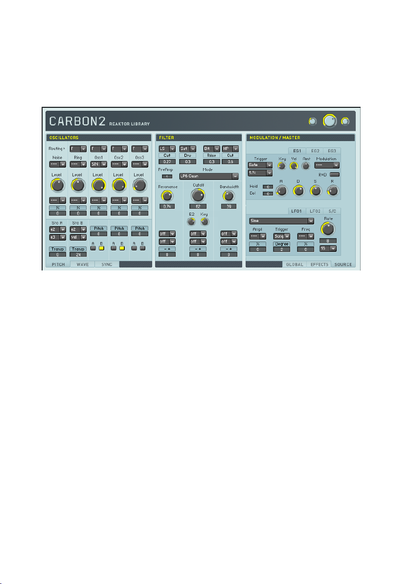
Carbon2 is based on Reaktor 4’s well-known workhorse synthesizer, but it has
been completely rebuilt. In particular the oscillators and filters are now based
on Reaktor Core components developed particularly for this instrument. The
panel has been optimized for usability, with a clear structure providing fast
access to all parameters while hiding the technical complexity.
Basically, Carbon2 is a classical subtractive synthesizer. The signal of the
three oscillator section (left column of the panel) passes through a multi-mode
filter (middle column) and is then routed to the effect units (right column).
Several modulation sources such as envelope generators and LFOs (placed
in a second page in the right panel column) and the global parameters (a
third page in the right column) control the sound, adding additional liveliness
and movement.
Oscillators
The oscillator section produces the instrument’s basic signal. Three oscillator
slots provide several different waveforms; along with traditional analogue types
like sine and sawtooth there is a digital wavetable oscillator containing a wide
array of waveforms that can be crossfaded smoothly. A noise generator and
Carbon 2 – 5REAKTOR 5
Page 6

a ring modulator based on the signal of the three main oscillators are added
for a total of five basic sound sources.
Each oscillator slot offers control over volume, pitch, and waveform synchronization. The pitch and sync controls are placed in two pages at the bottom of
the panel, grouped with a third page controlling the waveform. This third page
is only active if the digital wavetable or the doubled sawtooth is selected.
Main Routing Sets the destination of the respective oscillator’s signal. On [F],
the sound is sent to the [Filter] section; switching to [D] bypasses
the filter and routes the signal directly to the effect units.
Noise Switches the white noise generator on or off.
Ring Selects which oscillator signals are fed into the ring modulator.
Switch off to save CPU power if the ring modulator is not used.
Osc1/2/3
Level Sets the slot’s volume level.
Level Modulation
Source
Level Modulation
Amount
Pitch A/B Modulation
Source
A/B Modulation
Amount
Osc1/2/3 Pitch
Shift
Osc1/2/3
Modulation
Switch A/B
Selects the waveform of each oscillator slot. Along with the standard waveforms (sawtooth, pulse, triangular, sine and noise), you
will find a doubled sawtooth, a quantized sine, a buzz oscillator
based on a noise generator, and a digital wavetable. (See the
[Wave] page for additional information on the doubled sawtooth
and the digital wavetable.)
Selects the slot’s volume level modulation source.
Sets the amount and polarity of modulation applied to the slot’s
volume level. Clicking on the control’s title bar restores the value
to its default.
Selects sources to modulate the oscillators’ pitch. The two individual slots ([A] and [B]) can mix up to two sources.
Adjusts the amount and polarity of modulation applied to the
oscillators’ pitch. The left side of the control adjusts coarse values,
the right side is used for fine-tuning; clicking the control’s title
bar restores the value to its default.
Transposes the oscillators’ sound respectively. The left side of
the control adjusts coarse values, the right side is used for finetuning; by clicking on the controls title bar with the mouse the
value is reset to its default.
Turns modulation of the oscillator’s pitch by modulation slot [A]
or [B] on or off.
6 – Carbon 2 REAKTOR 5
Page 7

Wave A/B Modulation
Source
A/B Modulation
Amount
Osc1/2/3
Waveform
Control
Osc1/2/3
Modulation
Switch A/B
Sync Gate Sync Switch
Gate Sync Phase Controls the phase to which all oscillators are set on MIDI gate
Osc2/3 Sync
Switch
Osc2/3 Sync
Phase
Osc2/3 Mode
Fade
Selects sources to modulate the waveform. The two individual
slots ( [A] and [B]) can mix up to two sources. This will show no
effect until the doubled sawtooth or the wavetable is selected
in [Osc1/2/3].
Adjusts the amount and polarity of modulation applied to the
waveform. Clicking on the control’s title bar resets the value to
its default. This will show no effect until the doubled sawtooth
or the wavetable is selected in [Osc1/2/3].
This either selects a digital waveform from the wavetable, or – if
the doubled sawtooth is activated in [Osc1/2/3] – this controls
the ratio between the phases of both sawtooth waves.
Turns modulation of the waveform selection by modulation slot
[A] or [B] on or off.
Turns synchronization of the oscillators’ waveforms to the MIDI
gate on or off. If on, all three oscillators are reset to the phase
adjusted in [Gate Sync Phase] when a note is pressed.
events. Clicking on the control’s title bar restores the default
value.
Switches on or off the synchronization of the oscillators 2 and 3
respectively to the signal of oscillator 1. If on, the oscillator is reset
to the phase adjusted in [Osc2/3 Sync Phase] when the signal of
oscillator 1 rises above zero. (See also [Osc2/3 Mode Fade].)
Controls the phase to which the oscillators 2 and 3 are reset
when the signal of oscillator 1 rises above zero. Clicking on the
control’s title bar restores the default value. (See also [Osc2/3
Mode Fade].)
Interpolates between hard synchronization (at low values) and
soft synchronization (at high values). In hard synchronization
mode the oscillator is always reset if the signal of oscillator 1
rises above zero; with soft synchronization this is not always
the case, producing a mix between the synced waveform and
the non-synced one. Clicking on the control’s title bar restores
the default value.
Carbon 2 – 7REAKTOR 5
Page 8

Filter
The filter section is placed between the oscillators and the effects; it sculpts
the oscillators’ basic sounds. Before the signal is routed to the filter it passes
two effects that provide saturation and quantization, as well as additional lowand high-shelf equalizers. The filter itself contains several modes, optimized
for a warm yet crisp sound. You’ll find standard low-pass and high-pass, bandpass, and band-reject filters, a special feedback filter (called [Zwnl]), and a
peak EQ and comb filter. After the main filter comes another effect section,
similar to the previous one.
Pre-Filter
Effects
Main PreAmp
Effect A/B
Mode Select
Effect A/B
Amount
Mode
Cutoff Sets the frequency of the filter.
Resonance Sets the resonance of the filter.
Bandwidth
E2
Key
Selects the effect units applied to the signal before it passes to
the filter. There are low and high shelf EQs in the left [A] menu and
saturation and quantization in the subsequent right [B] menu.
Sets the parameter of the effect unit selected by [Effect A/B Mode
Select]. For the equalizers, this is the amount of damp or boost
applied to the signal. For the saturator it’s the amount of drive,
and for the quantizer it’s the amount of distortion.
Controls the level correction of the signal after it has passed the
[Pre-Filter Effects] section and before it enters the main filter.
Selects the filter mode. There are high-pass, bandpass and bandreject filters, several low-pass modes, a feedback lowpass, a
peak equalizer, and a comb filter.
Sets the width of the band for the bandpass and bandreject
filters. If the peak equalizer is selected, this parameter sets the
amount of boost applied.
Controls the amount and polarity of modulation applied to the
cutoff control by the second envelope generator. Turn to the left
for negative modulation, i.e. low cutoff values at high envelope
signals. Turn to the right for normal positive modulation.
Controls the amount and polarity of modulation applied to the
cutoff control by the current pitch. Turn to the left for negative
modulation, i.e. low cutoff values at high pitches. Turn to the right
for normal positive modulation. This modulation is independent
of the Key Scaler of the [Modulation] section.
8 – Carbon 2 REAKTOR 5
Page 9

PostFilter
Effects
Cutoff/
Resonance/
Bandwidth
Modulation
Source
Cutoff/
Resonance/
Bandwidth
Modulation
Amount
Effect A/B
Mode Select
Effect A/B
Amount
Selects the sources used to modulate the filter’s cutoff, resonance
and bandwidth. Up to two sources can be selected, and their
signals are summed together. In case of the cutoff modulation,
these signals are added to the hard-wired modulation by the
second envelope generator and the MIDI pitch.
Adjusts the amount and polarity of modulation applied to the
filter’s cutoff, resonance and bandwidth. Clicking on the control’s
title bar restores the default value. In case of the cut-off modulation, this amount doesn’t affect the hard-wired modulation by
the second envelope generator and the MIDI pitch.
Selects the effect units applied to the signal after the filter, before
it gets routed to the main effect units. You’ll find saturation and
quantization in the left [A] menu, and lowpass and highpass
filters in the right [B] menu.
Sets the parameter of the effect unit selected by [Effect A /B
Mode Select]. For the saturator this is the amount of drive; for
the quantizer the amount of distortion; and for both filters the
cut-off frequency.
Effects
The effects additionally enhance the instrument’s sound. There are five units:
a pitch shifter, a phaser, a chorus, an equalizer and a delay. These standard
effects are engineered for the finest of results.
Pitch
Shifter
Power & Mix
Shift L / R Determine the pitch shift of the left and right channel respec-
Grain Size L/ R Adjust the grain size of the pitch shifting algorithm for the left
Feedback Controls the amount of feedback.
Reverse Switches between forward and reverse grain playback.
Each effect unit provides a power switch and a mix button. The
mix button crossfades between the dry, unprocessed signal
(at the left) and the wet effect sound (at the right). To save
CPU power, turn the power switch off when the specific effect
is not in use.
tively in semitones.
and right channel respectively. Turn to the left for large chunks
and echoic sounds, to the right for tiny grains and an accurate
pitch shift.
Carbon 2 – 9REAKTOR 5
Page 10

Phaser Center Frequency
Modulation Rate Sets the speed at which the [Center Frequency] is modulated.
Phase Sets the phase of the LFO modulating the [Center Frequency].
Depth Sets the amount of modulation.
Resonance Sets the resonance of the internal filters.
Feedback Sets the amount of feedback.
Chorus Delay Sets the main delay of the chorus.
Depth Sets the amount of modulation applied to the [Delay] time.
Rate Sets the speed at which the [Delay] time is modulated.
Equalizer Bass Boost
Mid Frequency
Mid Boost
Mid Resonance Sets the resonance of the mid equalizer.
High Frequency Adjusts the frequency of the high shelf equalizer.
High Boost
Delay Delay L / R Sets the delay times of the left and right channel respectively.
Fine L / R Adds an offset to the values controlled by [Delay L / R] in mil-
Quantize
Feedback Sets the amount of feedback.
Wrap
Resonance
Lowpass
Highpass Controls the frequency of the high-pass filter within the feed-
Sets the center frequency of the filters that produce the phaser
signal.
(See also [Modulation Rate].)
Controls the boost (or damping) applied to the bass frequencies
below 300 Hz.
Adjusts the frequency of the peak equalizer applied to the middle
frequency spectrum.
Controls the boost (or damping) applied to the middle frequencies around the [Mid Frequency].
Controls the boost (or damping) applied to the frequencies above
the [High Frequency].
The time is controlled in increments selected by the [Quantize]
control.
liseconds.
Selects the unit by which the delay times are quantized. Sixteenth
notes and eighth triplets are available.
Controls the amount of cross-feedback. Turn to the left to route
the every channel’s feedback to itself; turn to the right to route
it to the other channel.
Sets the amount of resonance applied to the low-pass and highpass filters within the feedback circuit.
Controls the frequency of the low-pass filter within the feedback
circuit.
back circuit.
10 – Carbon 2 REAKTOR 5
Page 11

Modulation Sources
Several modulation sources are available: two ADSR envelope generators, a
recordable envelope, and two LFOs combined with a key-scaler that provides
four independent control points and four freely assignable MIDI controllers.
The envelope generators and LFOs offer several types of MIDI clock interaction for rhythm-based modulation effects.
Envelope
Generators
1/2
Trigger
Quantization
Key Controls the amount and polarity of modulation applied to the
Velocity
Transition Time
Modulation
Select
Transition Time
Modulation
Amount
Attack Sets the attack time of the envelope generator.
Decay Sets the decay time of the envelope generator.
Sustain Sets the sustain level of the envelope generator.
Selects the events that re-trigger the envelope generator. [Gate]
only activates the MIDI gate signal. [Clock Gate] re-triggers the
envelope at each unit selected by [Quantization] as long as the
MIDI gate is open. [SP Clock Gate] is similar, but synchronizes
the quantization to the global MIDI song position; therefore, the
MIDI clock has to be running. (See also [Globals][EG Mode].)
Selects the metrical unit used to re-trigger the envelope if
[Trigger] is set to [Clock Gate] or [SP Clock Gate].
envelope’s transition times by the current pitch. Turn to the left
for negative modulation, i.e. shorter attack, decay and release
times at low pitches. Turn to the right for normal positive modulation, i.e. longer times at low pitches.
Controls the current velocity’s influence on the envelope amplitude. At low values the envelope triggers with the same amplitude; at high values the MIDI velocity determines its peak
value.
Selects the additional modulation applied to the envelope generator’s transition times. The attack phase can be modulated by
the MIDI velocity while the decay time can be modulated by the
velocity and the four MIDI controllers (see [MIDI Controllers]). The
amount and polarity of modulation is controlled by [Transition
Time Modulation Amount].
Controls the amount and polarity of modulation applied to the
destination selected by [Transition Time Modulations Select].
Turn to the left for negative modulation, i.e. shorter attack or
decay times at low modulation source values. Turn to the right for
normal positive modulation, i.e. longer times at low values.
Carbon 2 – 11REAKTOR 5
Page 12

Release Sets the release time of the envelope generator.
Hold
Delay
R=D
Envelope
Generator
3
LFO 1/2 Waveform
Record
Play
Loop
Value
Amplitude
Modulation
Source
Amplitude
Modulation
Amount
Trigger Mode
Sets the duration of an additional hold phase between attack
and decay.
Adds an initial delay period before the trigger signal restarts
the envelope
Links the release time to the decay time. If on, the value adjusted
by [Decay] is also used to control the release phase.
Arms the recordable envelope. The recording is
started when a MIDI gate is received and ends
when the gate closes. All movements of the [Value]
knob are stored and can be played back as envelope
(see [Play]).
Enables playback of the recorded movements, triggered like an envelope by MIDI gate signals.
Loops the recorded movement on playback.
When recording (see [Record]), every movement of this knob is
stored to the memory. During playback (see [Play]), the knob
displays the recorded movements.
Selects the waveform of the Low Frequency Oscillator. There
are the standard waveforms [Sine], [Triangular], [Pulse], and
[Random Steps], and several derivations: [Pulse+] is a pulse
waveform with all negative values clipped to 0; [Saw Up+] and
[Saw Down+] are triangular forms with only rising resp.falling
ramp and only positive values; [Hsin+] is a multiplication of
[Pulse+] and [Sine] etc.
Selects the source used to modulate the LFO’s amplitude. Clicking
the control’s title bar restores the value to its default.
Adjusts the amount and polarity of modulation applied to the
LFO’s amplitude.
Selects the events that re-trigger the LFO. In [Freerun] mode no
reset occurs; in [Gate] mode the LFO is set to the phase adjusted
by [Reset Phase] on a MIDI gate event. [Clock Gate] is similar
to [Gate] mode but also activates a grid for the LFO’s frequency
(see [Rate]). [SP Clock Gate] additionally synchronizes the reset
to the global MIDI song position.
12 – Carbon 2 REAKTOR 5
Page 13

Reset Phase
Rate
Modulation
Source
Rate
Modulation
Amount
Rate
Rate
Quantization
KeyScaler Sliders
MIDI
Controllers
Faders
Adjust the phase to which the LFO is set on re-triggering
events.
Selects the source used to modulate the LFO’s frequency. If
[Trigger Mode] is set to [Clock Gate] or [SP Clock Gate], frequency modulation is not available.
Adjusts the amount and polarity of modulation applied to the
LFO’s frequency. Clicking the control’s title bar restores the value
to its default. If [Trigger Mode] is set to [Clock Gate] or [SP Clock
Gate], frequency modulation is not available.
Sets the frequency of the LFO. If [Trigger Mode] is set to [Clock
Gate] or [SP Clock Gate], a grid is applied to this control, quantizing the LFO’s rate to the metrical units selected in [Rate
Quantization].
Selects the metrical unit used as quantization grid for [Rate]
when [Trigger Mode] is set to [Clock Gate] or [SP Clock Gate].
Provides a signal derived from the current pitch that can be used
as modulation source. The four sliders define the function used
to map the MIDI pitch onto the modulation signal: At low pitches,
the value of the leftmost slider is used as modulation signal;
at high pitches the value of the rightmost slider is selected.
In between, interpolation occurs, using the two middle sliders
as control points. In addition to the normal signal, there is a
modulation source that multiplies the key-scalers value by the
current MIDI velocity.
The leftmost fader is hard-wired to the MIDI modulation wheel.
All others can easily be assigned to any MIDI Continues Controller
via MIDI Learn. They are available as modulations sources,
named C1, x1, x2 and x3.
Carbon 2 – 13REAKTOR 5
Page 14

Global Controls
The global controls access several different functions. First – and most important – the voice allocation of the synthesizer can be controlled, providing
polyphonic and monophonic modes; by selecting the unison mode all available
voices are set to the same pitch (as in a monophonic synth), but each one is
slightly detuned. This results in waveform interference and a thick, chorus-like
sound. Monophonic modes also provide portamento.
Parameters determine the master pitch shift and MIDI pitchbend range, and
adjust global tremolo and vibrato. Voices’ position within the stereo field can
also be adjusted.
Gate Mode
Envelope Mode
Unisono
Unisemi Sets the amount of pitch shifting applied to each voice when [Uni Mono]
Drift Enables a drift mode that slightly detunes higher pitches. This results in
Key
Velocity
Selects the global operation mode. [Poly] selects the only polyphonic mode;
portamento does not work in this mode (see [Glide Speed]). [Mono] results
in a monophonic gate signal that is triggered on every MIDI note. [Legato]
is similar but generates a new gate trigger signal only when the gate has
been closed before, i.e. no note is already pressed. [Uni Mono] and [Uni
Legato] activate the unison modes: A monophonic gate signal is used for
all voices, but all available voices are used and detuned by the [Unisono]
and [Unisemi] controls.
Selects the envelopes’ behavior during the release period if a new attack is
triggered. [Re-trigger] starts the attack phase beginning with the current
envelope amplitude; [Reset] starts the attack with a value of zero. Thus,
[Reset] might lead to unwanted clicks if used without care.
Sets the amount of detuning applied to each voice when [Uni Mono] or
[Uni Legato] is selected as [Gate Mode]. Slight detuning results in thick,
chorus-like sounds.
or [Uni Legato] is selected as [Gate Mode]. This acts like the [Unisono]
control but detunes the voices in semitones, e. g. a value of 12 will set all
voices one octave apart.
a more analogue like sound.
Activates key-scaling for the unisono control. If pressed, the [Unisono]
value is lowered automatically at high pitches for a more constant sound
over the complete pitch range of the instrument.
Selects the mapping applied to the MIDI velocity. While [Linear] doesn’t
change the velocity, [Log] results in a compressor like effect while [Expo]
produces the opposite effect.
14 – Carbon 2 REAKTOR 5
Page 15

Coarse
Fine
Glide Speed
Pitchbend Range
Vibrato Mode
Vibrato Amount
Vibrato Style Selects between three different vibrato modes.
Key
Tremolo Mode
Tremolo Amount
Vibrato & Tremolo
Frequency
Voice Panning
Switch
Voice Panning
Amount
Master 1/2 Defines the instrument’s output level. Use the large middle knob to adjust
Key Amp
Sets the global tuning of the instrument in semitones, ranging from -63
to +64.
Sets the global tuning of the instrument in semitones, ranging from -0.5
to +0.5
Adjusts the speed at which new pitches are reached if they are slurred,
i.e. if the previous note was still held when the new one was pressed. This
portamento effect only works in monophonic modes (see [gate Mode]).
Sets the range in semitones by which the MIDI pitchbend wheel transposes
the global pitch.
Selects whether vibrato is off, on, or faded in by the MIDI modulation
wheel.
Sets the amount of vibrato. Clicking the control’s title bar restores the
value to its default.
Adjusts the amount of key scaling applied to the vibrato. Turn to the left
for no scaling, to the right for less vibrato at low pitches, producing a
more musical effect.
Selects whether tremolo is off, on, or faded in by the MIDI modulation
wheel.
Sets the amount of tremolo. Clicking the control’s title bar restores the
value to its default.
Sets the speed of both vibrato and tremolo.
Selects whether the instrument’s voices are placed at different positions
within the stereo field. Especially in combination with the [Unisono] control
this can produce impressing spatial effects.
Sets the amount of voice panning. Clicking the control’s title bar restores
the value to its default.
the preset’s maximum level; the smaller knob to the right controls the
instrument’s output amplitude in all patches.
Adjusts the amount of automated amplitude correction in respect to the
synthesizer’s pitch. Turn to the left for no influence of the pitch onto the
output level, to the right to damp high pitches. This can be used to simulate
the sound of analogue synthesizers.
Carbon 2 – 15REAKTOR 5
Page 16
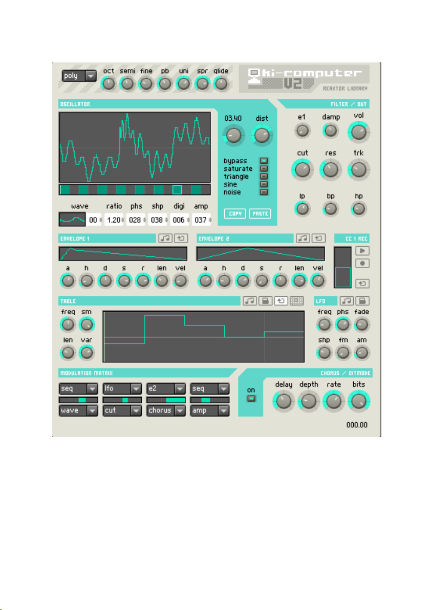
Oki Computer 2
If you get excited by words such as analog and vintage, look away now. Oki
Computer 2 is a compact wavetable synthesizer, a specialist in digital lo-fi
sounds that hails back to the era of 8-bit beeps and bleeps… It is also rather
capable at creating buzzing leads, rhythmic sequences, and odd tasty bass
tones.
Oki Computer 2’s panel is compact but packed with features. Thankfully, most
sections should be fairly straightforward to the average synth user. However,
16 – Oki Computer 2 REAKTOR 5
Page 17

the [Oscillator] section is somewhat unique and users are strongly encouraged to read this part of the manual. Oki Computer 2 features a bank of 50
waves. For every patch you can load any 16 of these waves into the oscillator
in any order. This flexibility represents a major improvement over the original
ensemble (where the oscillator was permanently ‘hardwired’ to the same 16
waves). What’s more, each wave loaded into the oscillator can be processed
in a variety of ways.
MIDI In
The drop-down list at the panel’s top-left switches between polyphonic and
monophonic operation modes. In polyphonic mode, Oki Computer operates as a
standard poly-synth. Monophonic mode does not restrict the number of voices
to 1; it enables some very musical features – legato, glide, and unison.
Gate Mode
Unison
Spread
Glide Sets the amount of portamento, i.e. the time used to reach a new MIDI pitch.
Octave Transposes the pitch of the entire oscillator in octave steps.
Semitone Transposes the pitch of the entire oscillator in semitone steps.
Fine Fine-tunes the entire oscillator’s pitch.
Pitchbend Defines the MIDI pitch bend wheel range in semitones.
Selects whether the instrument is used as polyphonic or monophonic synthesizer.
Determines the number of simultaneous voices. This is only active if [Gate
Mode] is set to [mono].
Defines the amount of voice detuning in semitones. This is only active if [Gate
Mode] is set to [mono].
This is only active if [Gate Mode] is set to [mono].
Oscillator
The [Wavetable Position Bar], located beneath the main oscillator window, is
perhaps the most difficult part of the synthesizer to understand. This bar has
two purposes. Firstly, the square box indicates the current wave slot selected
for editing (there are 16 slots). Secondly, the bright green line indicates
the current wavetable position. The current wavetable position is set by the
[Wavetable Position Knob] (to the left of the drive knob), plus any modulation
routed to the wave table position (see [Modulation Matrix]).
The best way to explain how the [Wavetable Position Bar] works is by example: Click on the snapshot menu and recall preset number 1 - ‘Default’.
Oki Computer 2 – 17REAKTOR 5
Page 18

In this preset, the oscillator is loaded with 16 sine waves (needless to say,
this doesn’t sound particularly interesting). Click the leftmost box on the
Wavetable Position Bar - this will select the first slot for editing. Note that in
the box labeled [Wave] (beneath the [Wavetable Position Bar]) a picture of a
sine wave is displayed, with a number zero next to it. This indicates that the
sine wave (wave number zero from the master bank) is loaded into the current
slot. To load a different wave, click and drag vertically on the Wave Selector.
Now click on the second wave slot (i.e. the adjacent dark gray box). The Wave
Selector will display a sine wave (remember this patch had 16 identical sine
waves loaded). Now try loading a different wave to slot 2, again by clicking
and dragging on the Wave Selector.
In the ‘Default’ snapshot, the [Wavetable Position Knob] is set to 1.00. This
means that when you play a note, you will hear (and see) the wave loaded
into slot 1. Press a note on your keyboard, and slowly move the knob from
1.00 to 2.00. You will hear and see the wave loaded into slot 1 morph into
the wave loaded into slot 2. Notice how the wave position indicator moves
correspondingly. This is the key to how Oki Computer 2 produces dynamic
sounds: by morphing between adjacent waves in the wavetable. While this
can be done manually with the wave position knob, things get much more
interesting when the various modulators (e.g. envelope, sequencer, LFO) are
used to mix between waves.
Apart from the Wave Selector, all the controls underneath the wavetable
position bar are used to modify wave shape. When using these controls, it
is important to remember that they only affect the wave in the selected slot
(i.e. the green box), which is not necessarily the wave shape currently being
played (i.e. the green line).
Ratio
Phase
Shape
Digitize
Amp
Copy
18 – Oki Computer 2 REAKTOR 5
Sets the number of times the wave shape will repeat in a
single oscillator cycle. Note that the integer and decimal
values can be set independently, also note that adjusting
the ratio will cause pitch shifting.
Rotates the wave start position within the oscillator cycle.
Skews the wave shape to either the left or right (on the pulse
wave this is identical to a pulse width control).
Reduces the wave’s bit depth.
Attenuates the wave volume.
Stores the current settings into an edit buffer that can be read out again
by the [Paste] button.
Page 19

Paste Recalls the data from the edit buffer (see [Copy]).
Distortion Amount Controls the amount of distortion. (See also [Distortion Mode].)
Distortion Mode
Selects the way the signal is distorted. [Saturate] applies a ‘standard’
saturation curve to the signal. [Triangle] and [Sine] both involve wrapping their respective shapes around the input signal. When used on a
sine wave, these two functions can sound somewhat reminiscent of FM.
[Noise] enables a noise generator.
Filter / Out
This section controls the shaping applied to the sound’s frequency spectrum
(filter) and amplitude.
Amplitude
Envelope Mode
Damp Controls the amount of high-frequency damping.
Volume Sets the main output volume in decibels.
Cut-off Sets the filter’s cut-off frequency.
Resonance Adjusts the filter’s resonance amount.
Track
Low-pass,
Band-pass,
High-pass
Selects the main output envelope. In most cases, [E1] will be the preferred
choice. Sometimes however, you may want to use Envelope 1 for modulation purposes only. In this case, select either [G] (MIDI gate, ignoring
velocity) or [Vel] (MIDI gate, including velocity).
Defines the amount of cut-off pitch tracking. At 100%, cut-off is increased by one semitone for each increment in MIDI pitch. At -100%,
cut-off is decreased by one semitone for each increment in MIDI pitch.
At +/- 200%, cut-off changes by two semitones for every one semitone
change in pitch.
Determines the mix ratio of the high-pass, band-pass and low-pass
components of the filter output signal.
Oki Computer 2 – 19REAKTOR 5
Page 20

Envelope, CC1, Sequencer and LFO
Oki Computer 2 features two envelope generators. Both can be used for
general modulation via the Modulation Matrix, but envelope 1 can also be
routed directly to output volume in the [Filter / Out] section. Otherwise, the
envelope generators are identical.
The CC1 section allows you to record modulation wheel movements. To record
a sequence, click the [Record] button. The button will flash, indicating that
it is armed and waiting. Recording will begin when a MIDI note is pressed,
and finish when the note is released (or when all recording memory is used
up). You can record movements with the mouse, or the CC1 knob on a MIDI
controller. As long as the [Play] button is depressed, recordings will play back
each time a note is triggered. The recording is sent to MIDI CC1. Therefore,
to use the recording as a modulation source, select CC1 in the Modulation
Matrix. Note that even though sequences are recorded monophonically, playback operates in full polyphony.
The sequencer is a highly flexible modulation source. It can operate as an
arpegiator, a custom shape LFO or an additional envelope. You can draw its
steps with the mouse.
You’ll find a standard LFO next to the sequencer.
Enve lo p e
1/2
CC1 Record
20 – Oki Computer 2 REAKTOR 5
Attack Controls the attack time of the envelope generator.
Hold Controls the hold time of the envelope generator.
Decay Controls the decay time of the envelope generator.
Sustain Controls the sustain level of the envelope generator.
Release Controls the release time of the envelope generator.
Speed
Velocity
Clock Sync
Loop
Play
Loop
Multiplies the overall envelope time.
Determines the extent to which envelope amplitude is
linked to velocity.
Synchronizes the envelope times to the global MIDI
tempo.
Activating this button results in the attack, hold and de-
cay stages looping when MIDI notes are depressed.
Arms the CC1 recorder.
Enables playback of the recorded movements, triggered
like an envelope by MIDI gate signals.
Loops the recorded movement on playback.
Page 21

Sequencer Clock Sync
Phase Lock
Loop
Snap
Frequency
Length Sets the sequencer length in steps.
Smooth
Variation
LFO Clock Sync
Phase Lock
Frequency
Phase
Fade
Shape
FM / AM
Synchronize the sequencer to the MIDI clock. Note
that when both [Clock Sync] and [Phase Lock] are
activated, the sequencer becomes locked to the MIDI
song position.
Locks the phase of the sequencer. When this is active,
MIDI note events will not re-trigger the sequencer.
Note that when both [Clock Sync] and [Phase Lock]
are activated, the sequencer becomes locked to the
MIDI song position.
When enabled, the sequencer will loop indefinitely,
otherwise it will play back only once when triggered.
Activates a vertical grid with a step size of 1/12 of the complete
height.
Determines the sequencer speed.
Determines the amount of interpolation between adjacent steps (at hard-right, the sequencer produces
smooth envelope-type output).
Imparts a kind of swing onto the sequencer movement,
so steps play alternately faster and slower. Center this
control for equal length steps.
Synchronize the LFO to the MIDI clock. Note that when
both [Clock Sync] and [Phase Lock] are activated, the
LFO becomes locked to the MIDI song position.
Locks the phase of the LFO. When this is active, MIDI
note events will not re-trigger the LFO. Note that when
both [Clock Sync] and [Phase Lock] are activated, the
LFO becomes locked to the MIDI song position.
Sets the LFO speed.
Determines the point in the LFO wave where oscilla-
tion begins when a note is triggered. This only function
when [Phase Lock] is off.
Sets the fade-in time of the LFO (i.e. the time taken
to reach full amplitude).
Skews the LFO shape to either the left or right.
Determine the amount which the modulation wheel
(including recorded movements) modulatea frequency
and amplitude respectively.
Oki Computer 2 – 21REAKTOR 5
Page 22

Modulation Matrix
The modulation matrix enables any four modulation sources to be routed to
any four destinations. You can select modulation sources using the upper
drop-down menus. Destinations are selected with the lower menus. The sliders
in-between these menu set the modulation amount. The full list of modulation
sources and destinations is summarized in the following table:
Sources Vel MIDI note on velocity (0 to 1)
PB MIDI pitchbend wheel (-1 to 1)
CC1
E2 Envelope generator 2 (0 to 1)
Seq The sequencer (-1 to 1)
LFO The LFO (-1 to 1)
Destinations Amp Output volume (-100% to +100%)
Pitch Oscillator pitch (-12 to +12 semitones)
Wave Oscillator wave position (-16 to +16)
Cutoff Filter cutoff (-60 to +60 semitones)
Chorus Chorus frequency (-100% to 100%)
MIDI CC1 - the modulation wheel. Note that
recorded CC1 movements (in the recordable envelope section) are routed to this
parameter.
(0 to 1)
22 – Oki Computer 2 REAKTOR 5
Page 23
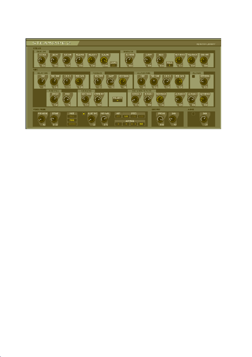
SteamPipe 2
SteamPipe 2 is a physical-modeling synthesizer that effectively models air
being blown through a tunable pipe. It uses a tuned resonator to create bowed,
blown, and plucked sounds, as well as strange new hybrid sounds. In addition
to a tuned all-pass filter and many controls for the “shape” of the pipe, there
is a mod wheel-controlled filter to achieve damping and breath noise effects.
The excellent-sounding SpaceMaster Deluxe reverb unit adds dimension to
the overall signal. You can find it on panel B.
SteamPipe 2 simulates air passing through a pipe of variable size and resonance. It’s physical-modeling techniques use contoured noise signals passing
through tuned and filtered feedback delays. The ensemble is basically split
into two parts: Steam and Pipe. The Steam module generates shaped and
filtered noise. Think of the Steam module as SteamPipe 2’s oscillator. Steam
provides the sound energy that will be pitch-formed by the Pipe. The Pipe
module gives the “wind” pitch and resonance. The patch also has an ADSR
volume envelope and a low pass filter. Both can be modulated by key- and
velocity-tracking.
Steam Pipe 2 can be a very expressive synthesizer, so make sure that you
plug in your MIDI keyboard and check out the presets with the mod wheel
in action.
Steam
The timbral shaping of the DC/Noise source occurs in the Steam section. The
SteamPipe 2 – 23REAKTOR 5
Page 24

low pass filter works in 1-pole or 2-pole mode, though the resonance control
only applies to the 2-pole filter. After the noise is filtered, the signal is fed
into the Pipe module.
Attack
Envelope
Decay
Sustain
Release
Velocity Controls the velocity sensitivity of the envelope. The higher this value is,
Scaling
Legato Toggles legato mode on or off. If on, the envelope restarts only when the
DC / Noise
Cutoff The cutoff frequency of the low-pass filter.
Generator
Reso
Poles Toggles between 1-pole and 2-pole low-pass.
Key-track Controls the key-tracking of the filter. This will scale the cutoff frequency
Vel-Track
Env-Amt Sets the amount of envelope to the cutoff frequency.
Sets the attack time of an ADSR envelope triggered by MIDI gate events
and used to generate a short initial steam signal; logarithmic control.
Sets the decay time of an ADSR envelope triggered by MIDI gate events and
used to generate a short initial steam signal; logarithmic control.
Sets the maximum level the envelope will reach. This gets modulated by
velocity if [VelSns] is on.
Sets the time that passes until the envelope is completely faded out after
the note-off signal.
the higher the peak value of the envelope will be.
This scales the envelope times depending on the pitch of the incoming
MIDI notes. Turn to the left for no keyboard scaling, to the right for shorter
envelope times on higher notes.
gate changes from zero to positive.
Crossfades between the DC component at the left and filtered noise at the
right. The mixed signal is used as steam input of the resonating pipe.
Sets the level of resonance of the filter. Only works when the filter is in
2-pole mode.
according to keyboard position. The lower the note pitch, the lower the
cutoff frequency will be.
Controls the velocity scaling of the filter. Turn to the right for higher cutoff
frequencies at higher MIDI velocities.
24 – SteamPipe 2 REAKTOR 5
Page 25

Pipe
The Pipe module is made up of a number of sub-modules for creating pitch
and resonance. The noise signal is fed from a single tuned delay providing
pitch, into the [Allpass] module for generating resonance. Next, a [Saturator]
receives the signal and applies edge and break-up. The [MW Filter] completes the signal chain with an overall tone shaping stage. The [Feedback]
and [Push-Pull] sections act on signals diverted from the main signal chain
and passed back into it via feedback loops. Unlike the [Feedback] section,
which simulates the pipe itself, the Push-Pull section controls the air and its
oscillations within the pipe.
The [Delay Tune] module contains the tuned delay that provides pitch to the
Steam. The [Tune] and [Fine tune] knobs allow you to set the signal’s fundamental pitch. The A440 oscillator at the bottom of the ensemble provides a
reference pitch for tuning purposes. The Delay pitch can be swept negatively
or positively by the mod wheel, with the amount of modulation set by the
[MW] knob.
The Allpass filter receives the tuned signal from the resonant delay. It can
be turned on and off with the [Power] button in the [Allpass] section. This
allpass can be tuned to create resonance effects. You can produce glassy,
metallic and bell-like sounds by detuning the allpass filter against the delay. By
adjusting the [Diffusion] knob, you can also create a variety of reverb sounds
- the simulation of air echoing along a pipe’s hard surface.
The Saturation module morphs between saturation and clipping, overdriving
or breaking up the signal before it hits the MW Filter.
The [MW Filter], controlled by the mod wheel, features a 1-pole high pass
followed by a 1-pole low pass filter. Each filter allows you to set a wheel-down
and a wheel-up setting, making it possible to set up complex timbre changes
and damping effects. Each filter can have its own [key track] setting.
The [Polarity] switch inverts the pipe polarity, changing the timbre of the sound.
This often transforms high frequency tones to deep ones and vice versa.
The [Feedback] module processes the feedback in the signal chain. The
[Rev-Time] knob extends or shortens the reverb generated by this feedback
signal. The reverb signal can be muffled with the [Damp] control. Damping
can be modified by [Key-Track] amount. High [Key-Track] values result in
more damping on higher pitches. This allows SteamPipe 2 to emulate struck
or plucked instruments like pianos, harps, and acoustic guitars.
SteamPipe 2 – 25REAKTOR 5
Page 26

Tune Sets the fundamental pitch of the signal. For standard musical tunings set
it to the [A440] oscillator at the bottom of the patch.
Fine Tune Fine control of signal pitch.
Delay Tune
SREC
Mod-Whl
Rev-Time
Feedback
Damp Sets the amount of high frequency damping of the pipe at key-up.
Key-track
Tune Controls the pitch of the allpass resonance. If the allpass filter is switched
Fine Tune Fine tunes the allpass resonance pitch. If the allpass filter is switched off,
Allpass Tune
SREC
Mod-Whl
Sample rate error correction. Adjusts the tuning correction of the pipe. When
the signal modifications in this patch and Reaktor’s sampling rate interfere
with the physical model of SteamPipe, this extra-fine pitch tuning becomes
necessary. Tune against the A440 section.
Sets the amount of pitch modification by the MIDI modulation wheel. This
simulates pitch changes of pipes getting blown softer or harder.
Adjusts the time of the pipe’s reverberation, i.e. the amount of damping applied to the feedback’s signal before it is mixed again with the new incoming
signal. The longer the reverb time, the more the incoming noise steam signal
becomes a tone with recognizable pitch.
Controls the feedback’s key-tracking. Turn to the right for longer reverb
times at high MIDI pitches.
off, this control shows no effect.
this control shows no effect.
Sample rate error correction. Adjusts the tuning correction of the pipe. When
the signal modifications in this patch and Reaktor’s sampling rate interfere
with the physical model of SteamPipe, this extra fine-tuning of pitch becomes
necessary. Tune against the A440 section. If the allpass filter is switched
off, this control shows no effect.
Sets the amount of pitch modification by the MIDI modulation wheel. This
simulates pitch changes of pipes getting blown softer or harder.
26 – SteamPipe 2 REAKTOR 5
Page 27

On / Off Turns the allpass module on or off. Switch on for additional attack effects
Allpass
of the pipe’s sound.
Diffusion
Offset
Push-Pull
Push Sets the amount of reverberating steam.
Soft /
Hard
Saturation
Symmetry
Polarity This control inverts the polarity of the pipe, thereby changing the timbre of
Polarity
Sets the diffusion of the resonances generated by the allpass module. Turn
to the left for additional attack effects of the pipe’s sound. It also enhances
the sound of harmonic frequencies which are not multiples of the main
pitch, like e.g. in bells.
Sets the offset amount added to the reverberating steam signal. This parameter influences the incoming steam and its reverberation in the pipe. It
interacts tonally with the Polarity button.
Controls the balance between soft saturation and hard clipping.
This parameter introduces level asymmetry into the signal. With increasing
asymmetry the positive part of the signal is reduced.
the sound. It interacts tonally with the [Push-Pull] section.
SteamPipe 2 – 27REAKTOR 5
Page 28

Hi Pass 0 Sets the cutoff frequency of an additional highpass filter within the pipe to
enhance formant frequencies. The formants are modified by the pressure
in the pipe (not by the pipe’s pitch). The pressure can be controlled by the
mod wheel. At low modulation wheel values this knob is used to determine
Mod-Wheel to filter
Hi Pass 1 Sets the cutoff frequency of an additional highpass filter within the pipe to
Key- t rack
High
Lo Pass 0 Sets the cutoff frequency of an additional lowpass filter within the pipe to
Lo Pass 1 Sets the cutoff frequency of an additional lowpass filter within the pipe to
Key-Track
Low
the formant frequency.
enhance formant frequencies. The formants are modified by the pressure
in the pipe (not by the pipe’s pitch). The pressure can be controlled by the
mod wheel. At high modulation wheel values this knob is used to determine
the formant frequency.
Controls the amount of key-tracking applied to the highpass filter’s cutoff frequency. Turn to the right for higher cutoff frequencies at high MIDI
pitches.
enhance formant frequencies. The formants are modified by the pressure
in the pipe (not by the pipe’s pitch). The pressure can be controlled by the
MOD wheel. At low modulation wheel values this knob is used to determine
the formant frequency.
enhance formant frequencies. The formants are modified by the pressure
in the pipe (not by the pipe’s pitch). The pressure can be controlled by the
mod wheel. At low modulation wheel values this knob is used to determine
the formant frequency.
Controls the amount of key-tracking applied to the lowpass filter’s cutoff frequency. Turn to the right for higher cutoff frequencies at high MIDI
pitches.
Global Controls
The last section of SteamPipe 2 consists of global controls over pitch, polyphony, glide, and an output stage. You also get an Arpeggiator and a test
tone generator.
28 – SteamPipe 2 REAKTOR 5
Page 29

Pitch Bend Sets the range of the pitch bend wheel.
Detune Introduces a slight detune into the signal for a livelier sound.
Mode
Voice Mode
Glide on / off Toggles glide on or off.
Glide Time This sets the time the pitch of SteamPipe takes to follow incoming
Mod-Whl
Arp Mode
Arp Speed
Spread Introduces a stereo spread into the main output.
Output
Gain Main output volume control.
A440 Tuning tone
A440
on / off
Gain Controls the volume of the 440Hz tuning tone.
Menu for the different polyphony modes. Choose between poly, mono,
unison, and three arpeggiator modes.
MIDI pitches, when [Glide] is on.
This knob follows an incoming mod wheel signal. Use it when you
have no hardware controller available.
This menu offers different arpeggiation modes. Choose between up
(>>), down (<<), up and down (>><<), and random.
Menu for choice between different speeds relative to the global
tempo.
If on, a sine oscillator’s signal is mixed into the main output. Use it
to tune the pipe. The frequency is 440Hz.
Space Master Deluxe
You can find this remarkable reverb module on panel B of the SteamPipe 2.
Based on several diffusion delays, Space Master can produce a wide array
of high-quality natural or experimental ambiences. The patch’s useful set of
reverb parameters include an early reflections section, a late reflections module,
and a post EQ. Dials for main reverb time, control of balance between the two
reflection stages, and between dry and wet signal round off the controls.
Input and output stage
You can put an initial delay into the reverb signal with the predelay [Time]
dial and control the predelay’s stereo position with the [Symmetry] knob. The
[Early / Late Balance] slider can be used to move the source in space – more
early reflections bring the signal to the front and more late reflections make
SteamPipe 2 – 29REAKTOR 5
Page 30

it appear further back in space. At the end of the signal chain the [Dry / Wet]
slider crossfades between original signal and reverb.
Time Sets an initial delay for the wet signal.
Symmetry
Predelay
Early/Late
Balance
Mixing
Dry / Wet This controls the balance between dry and wet signal.
Power button Switches the reverb on or off.
Introduces a difference into the delay times for the right and left predelay
channels. Use this to position the signal around in the stereo field.
With this parameter you can set how much of the early and late reflections, respectively, can be heard in the output.
Reflections
Use the two [Size] and [Diffusion] parameters to control two stages of variable
density diffused reflections. The early stage commonly represents the direct
response of the virtual space, whereas the late reflections define the sound
when the early reflections have died away.
For dynamic reverb effects you can use the Modulation section. It offers an
LFO routed to the delay times with [Rate] and [Depth] control. The LFO can
enhance your reverb signal by adding liveliness.
Size Determines the amount of space generated by the early or late reflec-
tions modules by adjusting delay time of the underlying diffusion delays.
Higher values give the impression of larger spaces.
Symmetry Introduces a stereo shift into the generated reflections.
Diffusion
Early / Late Reflections
Reverberation
Time RT60
Rate Control of LFO frequency modulating the delay times.
Depth Control for the LFO’s modulation depth. Higher values yield increased
Modulation
30 – SteamPipe 2 REAKTOR 5
Adjusts the perceived density of the reflections generated. Use for a
sparser or fuller reverb sound.
This control alters the decay time of the reverb response.
amplitude modulation.
Page 31

Frequency response
The two EQ sections serve slightly different needs. The Damping EQs are
integrated into the reflection stages and influence their frequency responses.
The Post EQ acts on the patch’s main output and should be used to finalize
the overall sound.
Low Freq
Damping
High Freq
Lo Damp Amount of cut for the low shelving filter.
Hi Damp Amount of cut for the high shelving filter.
Low Freq Cutoff for the low EQ that acts on the main output of the reverb.
High Freq Cutoff for the high EQ that acts on the main output of the reverb.
Equalizer
Lo Boost Cut or boost amount for the low Equalizer.
Hi Boost Cut or boost amount for the high Equalizer.
Cutoff for the low shelving filter that cuts into diffusion delay frequency
response of both early and late reflections.
Cutoff for the high shelving filter that cuts into diffusion delay frequency
response of both early and late reflections.
SteamPipe 2 – 31REAKTOR 5
Page 32

SubHarmonic
SubHarmonic generates pad-like, atmospheric sounds and – at the same time
– thick, monophonic lead patches. It consists of two independent sound generators: The [Sub Oscillator] is based on additive synthesis, and the [Formant]
section performs like an oscillator with a constant frequency vowel filter.
Internally, those oscillators are quite complex; the [Sub Oscillator], for example, does not use normal harmonics of the main frequency to perform additive synthesis, but produces subharmonics. However, those technical details
remain hidden below the simple user interface.
Voice
This section deals with the voice assignment. You have the normal monophonic
and polyphonic modes, and an additional unison mode that uses all available
voices (like polyphonic) but sets them to the same pitch, only slightly detuned.
The resulting phase interferences produce a chorus-like effect.
The amount of portamento and the influence of the MIDI pitchbend wheel
onto the instrument can also be adjusted here.
Voice Mode
Detune Sets the amount of detuning in [Uni] mode. Turn to the left for larger intervals
Glide Switches portamento on or off (see also [Speed]).
Speed
Pitchbend Sets the range of the MIDI pitchbend wheel in semitones.
32 – SubHarmonic REAKTOR 5
Controls the voice assignment of the instrument. [Poly] selects polyphonic,
[Mono] switches to monophonic behavior; [Uni] is also monophonic, but uses
all available voices which are slightly detuned to each other.
between the voices.
Adjusts the amount of portamento, i.e. the time that passes until a newly received
MIDI note’s pitch is gradually reached.
Page 33

Vibrato
Crucial to this instrument’s sound is the vibrato effect. It is produced by
mapping an LFO’s signal onto the instrument’s pitch. The LFO waveform, its
frequency, and the amount of pitch modulation can be controlled here, providing settings that differ from the normal idea of musical vibrato but generate
impressive sounds nonetheless.
Shape
Rate Sets the frequency at which the vibrato LFO oscillates.
Width
Amount Sets the amount of vibrato. Turn to the left for no vibrato, to the right for a pitch
Range Controls the absolute vibrato amount in semitones (see also [Amount]).
Selects the waveform of the LFO whose signal is used to modulate the instrument’s
pitch for vibrato effects.
Sets the pulse width of the vibrato LFO; turn to mid position for a symmetric
waveform.
modulation of the range adjusted by [Range].
Amplitude and Modulation Envelope
These two envelope generators, placed to the left (modulation envelope) and
the right (amplitude envelope) of the [Voice] and [Vibrato] sections, shape
the instrument’s amplitude and modulate the feedback amount of the [Sub
Oscillator] as well as the formant frequency of the [Formant Oscillator]. They
operate as normal ADSR envelopes, but offer additional re-triggering options,
key-scaling, and adjustable MIDI velocity sensitivity.
Mode
Attack Sets the attack time of the envelope generator.
Decay Sets the decay time of the envelope generator.
Sustain Sets the sustain level of the envelope generator.
Release Sets the release time of the envelope generator.
Key
Selects the way the envelope generator reacts to a new gate signal when the
previous gate is not yet closed. In [Leg] mode the envelope generator doesn’t
react to the new gate signal; in [Ret] mode it is re-triggered, using the current
envelope level as a starting point; in [Rst] mode the generator is also re-triggered, but reset to its initial level. This control shows no effect if [Voice][Voice
Mode] is set to [Poly].
Sets the amount and polarity of key scaling applied to the envelope generator’s
transition times. Turn to the left for faster transitions at low pitches, to the right
for slower transitions at low pitches.
SubHarmonic – 33REAKTOR 5
Page 34

Velocity
Sets the amount of MIDI velocity influence on the envelope’s amplitude. Turn
to the left for constant amplitudes that are independent of velocity, and to the
right for full velocity sensitivity.
Sub Oscillator
This oscillator creates the fundamental MIDI pitch which generates four subharmonics below this frequency. The ratio of the harmonics to the main pitch
and their amplitudes can be controlled individually, similar to a standard additive synthesizer. A feedback feature provides basic waveform modulation,
crossfading smoothly from a sine wave to one that sounds like a sawtooth
waveform.
Pitch
Harmonic
A/B/C/D
Amplitude
A/B/C/D
Feedback Amount
Envelope
Modulation Amount
Controls the pitch shift of the sub oscillator’s main frequency; there is a
coarse (top) and a fine (bottom) control. As the sub oscillator generates
harmonics below the main frequency, the pitch control shifts those sub
tones to a usable frequency.
Select four sub harmonics of the main frequency. Their volume is controlled by the respective [Amplitude] control.
Select the amplitude of the corresponding sub harmonic adjusted by
the [Harmonic] control.
Sets the amount of feedback applied to the sub oscillator internally.
Turn to the left for a undistorted sine-like sound, to the right for a
saw-like signal.
Controls the modulation amount applied to the [Feedback amount] by
the [Modulation Envelope].
34 – SubHarmonic REAKTOR 5
Page 35

Formant Oscillator
This particular oscillator is made up by a simple sine waveform; however,
the adjustable frequency band doesn’t move with the oscillator’s pitch, but
remains stable as a formant of the sound. By moving this frequency band you
can achieve vowel filter-like effects.
Pitch Controls the pitch of the main frequency; there is a coarse (top) and a fine (bot-
tom) control.
Formant
Frequency
Envelope
Modulation
Amount
Adjusts the frequency of the oscillator’s formant; this formant is not changed
by the main pitch.
Controls the amount and polarity of modulation applied to the [Formant Frequency]
by the [Modulation Envelope]. Turn to the left for inverse modulation, i.e. low
formant frequencies at high modulation signals, and to the right for normal
modulation, i.e. high formant frequencies at high envelope levels.
Mix and Output
In this section the signals of both oscillators can be mixed, positioned in the
stereo field, and leveled.
Mix
Spread Sets the amount of displacement within the stereo field applied to the instru-
Gain Sets the output gain.
Crossfades between the sound of the sub oscillator (at the left) and the signal
of the formant oscillator (at the right).
ments’ voices. Turn to the left for a mono signal, and to the right to pan each
voice individually; this is particularly impressing if [Voice][Voice Mode] is set
to [Uni].
SubHarmonic – 35REAKTOR 5
Page 36

Reverb
The high-quality reverb unit is contained within the panel’s B view. It can
further enhance the sound’s spatial characteristics. When not in use it should
be turned off by the [Power] control to save CPU power.
Size Sets the size of the virtual reverberation room.
Symmetry Places the signal in the virtual reverberation room. Turn to the left or right to
move the signal away from the center.
Diffusion Sets the amount of reverb signal diffusion. Turn to the right for a less echoic
sound.
Release Adjusts the time that passes before the reverberation sound has decayed.
Spin
Frequency Sets the rate of the LFO used as modulation source (see [Spin]).
High Cutoff
High Damp
Low Cutoff
Low Damp
Mix
Power
Sets the amount of modulation applied to the reverb. Technically, the modulation
affects the delay time of the delay modules on which the reverb is built.
Sets the cutoff frequency of the lowpass filter that is damping the high fre-
quencies.
Sets the amount of damping applied to the frequencies above the [High Cutoff]
frequency.
Sets the cutoff frequency of the highpass filter that is damping the low fre-
quencies.
Sets the amount of damping applied to the frequencies below the [Low Cutoff]
frequency.
Crossfades between the unprocessed, dry signal (at the left) and the reverber-
ated, wet sound (at the right).
Switches the reverb unit on or off. Turn off to save CPU power when the reverb
is not in use.
36 – SubHarmonic REAKTOR 5
Page 37

Grooveboxes
Aerobic
Aerobic is a step sequencer that controls a virtual analogue drum synthesizer.
The instrument produces tight, innovative sounds far beyond the range of traditional drum computers. This, combined with the sequencer’s capacities and
the mixer’s flexible routing options, makes Aerobic a versatile beat production
environment that can be used in live performances.
Aerobic – 37REAKTOR 5
Page 38

The drum synthesizer contains six similar, independent units (selectable by
the tabs at the top of the panel). Each unit combines an oscillator and a noise
section into one signal that can be equalized before it is sent to the master
mixer. The sequencer (in the middle of the panel) contains two tracks for each
sound unit, selectable via the same tabs as the units themselves. The filled
rectangles within the sequencer’s display represent the unit’s trigger signals
and their velocity; the unfilled rectangles form a modulation track whose signal
can be used to change nearly every parameter of the sound engine and mixer
over time: Use the [Modulation] switch in the unit’s master section to select
the destination of the modulation. The master mixer provides classical mixing
parameters for each unit (solo/mute, pan, and, of course, level), along with
controllers to adjust the complete ensemble’s reaction on MIDI messages.
Each unit can be triggered by a selectable MIDI note; on a more complex
level, note messages can recall complete ensemble snapshots.
Sound Engine
The drum synthesizer is built by two sound generators, an equalizer, and
a master section that also controls modulation routing. While the oscillator
part (on the left side) is based on sine waveforms with frequency modulation
capacities, the noise part (on the right side) contains a white noise generator
with a multi-mode filter. The mixed signal is sent through an EQ and (within
the master section) a final saturator unit before it is passed on to the mixer.
Envelope
Oscillator
Attack Sets the time that passes until the amplitude envelope reaches its peak. In
Decay
38 – Aerobic REAKTOR 5
Selects the operation mode of the envelope shaping the unit’s amplitude.
[Lin] activates a standard AD envelope whose transition times are controlled by the [Attack] and [Decay] knobs. When in [Roll] mode, this envelope
is re-triggered fast until the next beat; the [Attack] knob in this case also
controls the re-triggering frequency. [Roll+Lin] adds both signals of the
modes described above. [Noise Env] uses the envelope of the Noise section
(see below).
[Roll] mode (see [Envelope]) the knob also controls the rate at which the
envelope is re-triggered.
Sets the time that passes after the amplitude envelope has reached its peak
before it decays to silence.
Page 39

Oscillator
F-Mod Selects the source signal used to modulate the main oscillator’s frequency.
F Sets the base frequency of the main oscillator.
FMod Sets the amount of frequency modulation applied to the main frequency by
Rate
Mix
Mix
Envelope Similar to [Oscillator][Envelope], applied to the noise generator’s filter.
Noise
Attack Similar to [Oscillator][Attack], applied to the noise generator section.
Decay Similar to [Oscillator][Decay], applied to the noise generator section.
Noise
Filter
Freq Sets the center frequency of the filter.
Peak
Res Sets the amount of filter resonance.
Hz Sets the frequency of the equalizer.
EQ
dB Sets the amount of volume boost (or cut) applied to the adjusted
Selects the operation mode of the oscillator. While [Sin] represents a standard
sine wave, [Sin2] activates a squared sine wave with a different frequency
spectrum. Similarly, [FM2] selects the squared signal of [FM] which is generated by a sine oscillator modulating the frequency of another one. (This
frequency modulation does not interfere with the modulation controlled by
[F-Mod], [F] and [Fmod].) [Phase] uses the output of a phase oscillator.
While [Osc Env] and [Noise Env] select the respective amplitude envelopes,
the [Sine], [Tri] and [Random] entries use independent oscillators whose
frequency can be adjusted with [Rate].
the selected source signal.
Sets the frequency of the independent oscillator modulating the main oscil-
lator’s frequency.
Sets the ratio of the oscillator section’s output and the noise section’s sound
in the signal that is passed on to the equalizer.
Selects the operation mode of the noise section. [White] uses unfiltered
noise, [White Mod] modulates the noise generator’s algorithm by the noise
section’s envelope signal.
Selects the type of 2-pole filter applied to the noise. Highpass, bandpass,
and lowpass filters are available, providing 24 dB damping per octave.
Sets the amount of modulation applied to the filter’s center frequency by
the envelope.
frequency.
Aerobic – 39REAKTOR 5
Page 40

Modulation
Master
Track
Amp Sets the amplitude of the signal before it is routed to the final shaper unit
Shape
Selects the target of the sequencer’s modulation track. The modulation shows
no effect until the [Track] button is pushed.
Activates the modulation of the target selected by the sequencer’s modulations track.
(see [Shape]).
Selects the operation mode of the shaper unit. [Polysat], [Sinesat], and
[Hypersat] saturate the signal with tube-like effects; the effect increases
the more the signal is amplified before (see [Amp]). [Clean] doesn’t perform
any compression; [Amp] simply controls the amount of amplification before
the signal is routed to the master mixer.
Sequencer
The sequencer provides two tracks for each of the six drum synthesizer units:
a gate pattern and a modulation track. The gate pattern determines the trigger
signals and their velocity. The modulation track signal can be routed to any
parameter of the sound engine (see [Sound Engine][Master][Modulation]).
A roll mode bar provides three different roll modes for fast re-triggering of a
drum sound.
Tempo
Global Tempo Sets the [Tempo] value of all six tracks.
Swing
Roll Factors
Init All
Track Selects the track that can be edited within the [Edit Display]
Step Count
40 – Aerobic REAKTOR 5
Selects the tempo of the track: Each step of the sequence can be interpreted
as sixteenth note, etc. Thus, the sequencer is always synchronized to the
master MIDI clock; use the host sequencer or Reaktor’s internal MIDI clock
to start the sequencer. (See also [Global Tempo].)
Sets the amount of swing, i.e. the amount by which every second step of
the sequence is delayed to shuffle the strict MIDI rhythm.
Sets the number of times the trigger signal is repeated if the [Roll Mode]
is set to the respective colors.
Deletes all sequence patterns and modulation tracks and sets [Swing] to
its default values.
Displays the number of the current step (1 to 16). If the gate is off, the
number is dark; if the gate is on, the number is light. This can be helpful
when editing the modulation track.
Page 41

Edit Display
Roll Mode
Loop Controls the length and position of the played sequence: Only those steps
Displays the trigger pattern (filled rectangles) as well as the modulation track
(unfilled rectangles), depending on the [Track] setting. Clicking within the
display allows the patterns to be edited. High values of the trigger pattern
represent high velocity; in the modulation track they cause the modulated
knob to turn to the right, and low values turn the knob to the left.
Selects how often the trigger signal is sent. Normally, it is only sent once
per beat; by clicking with the mouse one can step through three differently colored modes where the trigger signal is sent more often (see [Roll
Factors]).
within the rectangle are used. Drag the ends of the rectangle to adjust the
loop’s start and end points. A second, smaller bar represents the current
read out’s position.
Master / Mixer
This section has two functions. First, it mixes the six drum synthesizers down
to a single signal – or to four signals if [Single Outs] is activated. Second, it
controls the snapshots of the complete ensemble as the sound engine and
the sequencer are slaved to this part of the instrument. An advanced recall
system allows for fast changes of sound/pattern settings via a single MIDI
note, making the complex drums computer-controllable from a keyboard in
live stage use.
Level Sets the volume of the sound unit.
Mixer
Solo Switches the sound unit to solo playing, i.e. mutes all other units.
Mute Mutes the sound unit.
Pan Positions the sound unit’s mono signal within the stereo field.
Wide Enhances the spatial appearance of the sound unit.
Ext. Learn Activates the learn feature. When pressed, the next MIDI note will be as-
signed to this track and can be used as external trigger signal, in addition
to the internal gate signals of the sequencer. (See also [External].)
Output Selects to which of the four stereo outputs the sound unit is routed. This
shows no effect until [Single Outs] is activated.
Aerobic – 41REAKTOR 5
Page 42

Power Switches the snapshot handling on or off.
Key
Snapshot
Quantize
Quantization
Select
Snapshot
Root Snap
R o o t S n a p
Learn
Root Note
R o ot N ot e
Learn
Store
Store +1
Master Sets the master volume.
Level
Velocity
Single Outs
External
Turns on or off snapshot recall by external MIDI note messages. See [Root
Note] and [Root Snap] for details.
Turns quantization of external MIDI notes on or off. When on, incoming MIDI messages will be synchronized to a pattern that is selected by
[Quantization Select].
Selects the quantization pattern to which external MIDI messages can
be synchronized.
Recalls a snapshot of the master mixer. Since all other components are
slaved to this one, storing or recalling a snapshot here affects all other
instruments, i.e. the sound units and sequencer.
Sets the snapshot number recalled when the MIDI note adjusted by [Root
Note] is received; [Snap Via Key] has to be activated. The note above [Root
Note] recalls the snapshot that follows on the [Root Snap] etc.
The first snapshot recalled after pressing this button will be used as new
[Root Snap].
Sets the external MIDI note that, if [Snap Via Key] is on, recalls the snapshot
adjusted by [Root Snap].
The first MIDI note received after pressing this button will be used as
new [Root Note].
Stores the current settings of the complete ensemble to the current snapshot number (see [Snap]). If [Store To Next Snap] is activated, the subsequent snapshot number will be used to store the data. Any data previously
stored there will be overwritten. Therefore, one should start a completely
new bank of snapshots when working on a project.
If activated, upon pressing [Store] the settings of the complete ensemble
will not be saved to the current snapshot as displayed by [Snap] but to
the next one.
Slaves the [Master] control to the velocity of incoming MIDI notes used
to recall snapshots.
Switches on or off the sound units’ routing to different outputs. When off,
all sound units are mixed to one stereo signal; when on, there are four
stereo outputs to which the six sound units can be individually routed
(see [Output]).
Switches on or off the triggering of the sound units by external MIDI notes.
When off, the sound units are only triggered by the internal sequencer.
(See also [Ext. Learn].)
42 – Aerobic REAKTOR 5
Page 43

Massive
This drum computer is “massive” in at least two ways. First, it contains a
vast range of signal-shaping capacities: samples in the six drum tracks don’t
determine the instrument’s sound (like in a standard drum machine), but
only provide the material from which the beats can be sculpted. Envelopes,
filters, and a potent grain re-synthesis algorithm mangle the fundamental
sound until it is completely different, but still musical. Second, these versatile
sound editing features are combined with an advanced step sequencer system
offering copy and (looped) paste functionality, three different roll modes, a
triplet mode, independent loop length for each of the six drum tracks, three
modulation tracks whose signal can be routed to nearly every parameter of
the sound engine – the list of features could be continued.
Yet, those capacities are not hidden behind an endless array of knobs and
faders that prevent productive working. The panel is optimized for usability
and fast access to all controllers, making Massive to a powerful sound design
workstation. And at the same time – thanks to a complex and glitch-free snapshot recall system – Massive can be used in live performances, or as a slave
to a master song sequencer that changes the snapshots automatically.
Massive – 43REAKTOR 5
Page 44

Control
At the top of the panel you’ll find the instrument’s control section. On the
left, an edit mode section defines how the various step sequencer displays
react to mouse actions. The copy and paste controls are here too. Next to it
is the snapshot management system, followed by the quantization and timing
controls, and the parameters for external send effects. Finally, there is the
master output knob to adjust overall volume.
There are two external effects: a delay unit, and a lo-fi reverb to enhance the
sound spatially. Both effects have three parameters that can be controlled
from Massive’s main panel. Additional parameters can be edited in the effects’
own panel, which also contains a normalizer and equalizer. Press {Ctrl}+{2}
to go to a second panel set where the effects are displayed; press {Ctrl}+{1}
to return to the main panel.
Edit Mode
Edit
Copy! If [Remote] is selected as [Edit Mode], pressing this button activates
Paste! If [Remote] is selected as [Edit Mode], pressing this button activates
Lock
Edit Buffer Displays the content of the buffer into which data is copied in [Copy]
Selects the way the various step sequencer displays react to mouse actions. When [Draw] is selected, the mouse can set each step value (see
also [Lock] and [Sequencer][Value Display]). When [Copy] is activated,
an area of steps can be selected with the mouse that is automatically
copied to the [Edit Buffer]. In [Paste] mode the buffer’s data is copied
back to any area selected with the mouse; if the paste area is longer
than the buffer’s content, the material to be pasted is looped. [Remote]
enables the separate [Copy!] and [Paste!] buttons.
the same behavior of the step sequencer displays as the separate
[Copy] mode of the [Edit Mode]. This button can easily be activated
by pressing the {C} key on the computer keyboard (i.e. MIDI note 52).
Thus, one can quickly edit the sequencers’ data with one hand on the
keyboard and one on the mouse. (See also [Paste!] and [Lock].)
the same behavior of the sequencer displays as the separate [Paste]
mode of the [Edit Mode]. This button can easily be activated by pressing the {V} key on the computer keyboard (i.e. MIDI note 53). One can
quickly edit the sequencers’ data with one hand on the keyboard and
the other on the mouse. (See also [Copy!] and [Lock].)
Keeps the mouse locked on the selected sequencer step in [Draw] mode
(see [Edit Mode]). This can also be activated by pressing the {Z} key
on the computer keyboard (i.e.. MIDI note 48).
mode and that is used in [Paste] mode (see [Edit Mode]).
44 – Massive REAKTOR 5
Page 45

Snapshot Store With the left mouse button, a snapshot slot number can be selected;
by pressing the right mouse button, the current instrument settings
Snapshot
Snapshot Recall
Snapshot Mode
Page Switch
Quantization
Select
Quantization and Timing Effect
Shuffle Scales the preset of the [Quantization Select] control. Turn to the left
Grid
Timing Sets the micro delay for each track.
A1 Controls the cut-off frequency of the low-pass filter placed within the
A2
A3
B1
(including all sequencer data) is stored into this slot.
Displays a list of the available snapshots; selecting a snapshot with
the mouse results in recalling its data, including all sequences, but
playback is not interrupted.
Selects whether the snapshots are only recalled via internal signals
or if external control signals received at the instrument’s [Snap] port
are recognized, too. This allows you to connect to a master song sequencer.
Switches between the quantization controls and the timing parameters
to be displayed. One page has the [Quantization Select], [Shuffle] and
[Grid] parameters, the other contains the [Timing] controls to adjust a
micro delay for each track.
Selects one of twelve quantization presets. Each preset ranges over
sixteen steps; the higher the displayed value, the more delay is applied
to this step. The first preset, for example, alternates between low and
high values, so every second step will be delayed, resulting in a standard
off-beat shuffle. The presets only define relative times; the effective
delay time at maximum values is set by the [Shuffle] control.
for no quantization (independently of the selected preset), to the right
for full delay times. See also the [Sequencer] section for interaction
with triplet modes.
Selects the grid of the sequencer displays; it does not affect the
sound.
feedback circuit of the external delay unit.
Crossfades between pre-delay gating (at the left) and post-delay gat-
ing (at the right)
Gates the signal of the external delay effect. Turn to the left to close
the gate, turn to the right to open it. Depending on the [A1] setting,
the audio signal will be gated before it is sent into the delay effect or
after the effect unit. This parameter can be modulated (see [A/B 2
Modulation Select]).
Controls the internal cutoff of the spatializer. Use this to alter the color
of the effect sound.
Massive – 45REAKTOR 5
Page 46

B2
B3
A/B 1/2/3
Modulation
Select
Return A/B
Quantization and Timing Effect
Master Volume
Output
Controls the internal resonance of the spatializer. Use this to color the
effect sound.
Gates the signal of the second external effect after the unit. Turn to
the left to close the gate, turn to the right to open it.
Selects the modulation track whose signal modulates the value of the
respective controller.
Sets the level of the signal that is returned from the first / second
external effect; there is an additional [Mute] button that switches the
sound completely off.
Controls the master volume of the instrument. An additional [Mute]
button switches the sound completely off.
Modulation
The three step sequencers of this section don’t trigger samples but function
as modulation sources to change a sound engine parameter synchronized to
the six sample sequencers. Each of the modulation tracks is identified with
a color that can be selected within the various modulation source selection
controls (e. g. below the Transpose control of the Master section). Normally,
you adjust the modulation amount below the source selection control of the
modulated parameter.
Track Select
Sequencer
Display
Half Tempo
Switches between modulation track 1 (blue), 2 (green) and 3 (orange). All three
tracks can be used to modulate various parameters of the instrument, selectable
in the various modulation source controls.
The modulation tracks’ step sequencers act like the one described in the
[Sequencer] section; the only difference is the absence of a roll mode.
Switches between normal and half speed of the resp. track read out: when
pressed, each step is interpreted as a eight note; otherwise each step is interpreted as a sixteenth note. (See also [Sequencer][Triplet Display].)
Sequencer
Each step sequencer display provides three rows of controllers. At the top there
is the main display with 32 steps, read out as sixteenth notes. They represent
gate values, i.e. the step’s velocity. When the gate is completely closed (i.e.
the bar is a pulled to the bottom), the sampler unit is not triggered at all.
While the normal gate values are controlled with the left mouse button, holding down the right mouse button and moving the step’s value up and down
46 – Massive REAKTOR 5
Page 47

enables rolls, represented as different colors of the step’s bar. In roll mode,
the sample is not only triggered once at the beginning of the step, but several
times within the step’s time.
Below the main step display there is triplet mode control. A yellow bar represents the normal mode, and a shorter red bar appears in triplet mode.
Click on the left side of the bar for triplet mode, click on the right for regular
mode. In triplet mode, every group of four notes (i.e. steps 1-4, steps 5-8
etc.) can be interpreted as eighth triplets; in this case the last note of the
group is not played.
The roll modes depend on the triplet control as seen in the following table:
Duolen No roll Sixteenth notes
Roll 1 Thirty-second notes; the step is triggered twice
Roll 2 Thirty-second triplets; the step is triggered three times.
Roll 3
Thirty-second note triplets. Every first
and second step are quantized differently; setting two subsequent steps
to this roll mode results in the displayed pattern. An alternation of this roll
mode and no roll mode for two subsequent steps, combined with a regular
shuffle of about 66%, thus leads to sixteenth triplets.
Triplet No roll Eighth triplets.
Roll 1 Sixteenth triplets; the step is triggered twice.
Roll 2 Thirty-second triplets; the step is triggered four times.
Roll 3 Similar to Roll 2.
In the last row each track has a loop control, dictating which sequencer
area loops when the instrument plays. Click and drag the mouse to select
the loop area. A small marker indicates the current read-out position within
the loop.
Value Display
Displays the main sequence steps. The height of each step’s bar represents
the velocity of the gate signal produced when the sequencer is running.
Depending on the [Control][Edit][Edit Mode], the values can be drawn
manually, copied to the edit buffer, or pasted from that buffer using the left
mouse button. Movements with the right mouse button pressed activate the
roll mode for each step independently, changing the step’s color.
Massive – 47REAKTOR 5
Page 48

Triplet Display Switches between normal read-out (the steps are interpreted as sixteenth
notes) or triplet read-out (the steps are interpreted as eighth triplets) of the
group of four steps above each controller. In triplet mode, the fourth note is
not played. See the explanations above.
Loop Display Controls the length and position of the loop to be played. A moving marker
shows the position of the read-out when the sequencer is running.
Sound Engine
The sound engine contains a master section and six independent sampler
units. The master section is located to the right of the modulation section; it
sets global sample select offset and scales other parameters for all samplers
simultaneously. If, for example, [Master][Transpose] is set to 12, all transpose
controls of the six drum tracks are scaled from 0 to 12 semitones; if the master
control is set to 0, transposition is switched off for all tracks.
The parameters that control the samplers are grouped across four pages. The
main page contains the sampler module itself where you load sample files; on
the panel it is represented by the sample’s waveform. Further controls select
the sample from the map and adjust the pitch shift. The envelope section
controls the sample’s amplitude. The parameters of this page can be used to
fine-tune the sample, particularly the influence of the gate velocity on attack
and decay times. The filter section contains a low-pass and a high-pass filter
whose sound can be smoothly crossfaded. The grain section, finally, controls
the grain re-synthesis of the sampler; it is only available in the upper three
sampler tracks. Here the speed of the sample traversal can be controlled as
well as the grain size, which greatly influences the sound of the re-synthesis
algorithm.
48 – Massive REAKTOR 5
Page 49

Sample Select Adjusts an offset for all [Sampler][Sample Select] controls of the
Master
Sample Select
Modulation Source
Sample Select
Modulation Amount
Transpose
Transpose
Modulation Source
Transpose
Modulation Amount
Decay Scale
Cutoff Scale
Drive Scale
Transpose Scale Scales all sample transpositions adjusted independently for each
Grain Scale
Reset
six independent sampler tracks.
Selects the modulation track that modulates the [Sampler][Select]
parameter. (See also [Sample Select Modulation Amount].)
Controls the amount of modulation applied to the [Sampler][Select]
parameter by the track selected in [Sample Select Modulation
Source].
Adjusts an offset for all [Sampler][Transpose] controls of the six
independent sampler tracks. (See also [Transpose Scale].)
Selects the modulation track that modulates the [Transpose] parameter. (See also [Transpose Modulation Amount].)
Controls the amount of modulation applied to the [Transpose] parameter by the track selected in [Transpose Modulation Source].
Scales all decay times adjusted independently for each sampler
track with the [Sampler][Decay] control.
Scales all filters cut-off frequencies adjusted independently for
each sampler track with the [Sampler][Cutoff] control.
Scales all pre-filter saturation drive amounts adjusted independently
for each sampler track with the [Sampler][Drive] control.
sampler track with the [Sampler][Transpose] control. (See also
[Transpose].)
Scales all grain sizes adjusted independently for each sampler
track with the [Sampler][Grain] control. The grain parameter is
only available for the upper three sampler tracks.
Restores the values of all sampler tracks and the master section
to default values.
Massive – 49REAKTOR 5
Page 50

Selects the page displayed on the panel, controlling the [Sound
Engine][Sampler] section. The [Main] page contains the following
Page Select
Sample Map Editor Displays the currently selected sample (see [Sample Select]).
Sample Select
Sample
Sample Select
Modulation Source
Sample Select
Modulation Amount
Transpose
Transpose Modulation
Source
Transpose Modulation
Amount
Velocity
Decay Sets the decay time of the amplitude envelope triggered by a gate
parameters: [Select], [Transpose] and [Reset]. The [Envelope] page
contains the following parameters: [Mute by Track], [Velocity],
[Decay], [Dynamic Attack] and [Dynamic Decay]. The [Filter] page
contains the following parameters : [Drive], [Filter Power], [Cutoff],
[Resonance] , [Low-pass / High-pass Crossfade] and [Reset]. The
[Grain] page is only available for three of the six sampler tracks; it
contains the following parameters: [Speed], [Grain] and [Reset].
The controls for [Pan], [Send Level] and [Track Level] are available
in every page. Additional modulation controls are available for some
of the controls mentioned above.
Selects the track’s sample played upon a trigger signal of the step
sequencer. (See also [Sound Engine][Master][Sample Select].)
Selects the source that modulates the [Sample Select] parameter.
(See also [Sample Select Modulation Amount].)
Adjusts the amount of modulation applied to the [Sample Select]
parameter by the source selected in [Sample Select Modulation
Source].
Sets the amount of transposition applied to the selected sample. For
the upper three sampler tracks this transposition does not affect the
sample’s playback speed (due to the underlying grain resynthesis
algorithm); for the three lower sampler tracks it also changes the
playback speed. (See also [Sound Engine][Master][Transpose] and
[Sound Engine][Master][Transpose Scale].)
Selects the source that modulates the [Transpose] parameter. (See
also [Transpose Modulation Amount].)
Adjust the amount of modulation applied to the [Transpose] parameter by the source selected in [Transpose Modulation Source].
Adjusts the amount of influence of the sequencer’s gate velocity on
the sample’s amplitude. Turn to the left for no influence, i.e. constant
maximum amplitude at every gate value; turn to the right for a
complete mapping of the gate value onto the sample’s amplitude.
event. (See also [Dynamic Decay] and [Sound Engine][Master][Decay
Scale].)
50 – Massive REAKTOR 5
Page 51

Dynamic Attack
Dynamic Decay
Dynamic Source Selects the source track that modulates the amplitude envelope’s
Mute By Track
Drive
Filter Power Switches the track’s filter on or off.
Cutoff
Cutoff Modulation
Source
Cutoff Modulation
Amount
Resonance Sets the resonance of the track’s filter.
Lowpass / Highpass
Crossfade
Speed
Speed Modulation
Source
Sets the amount of modulation by the source selected by [Dynamic
Source] applied to the attack time of the amplitude envelope. Turn
to the left for no modulation; turn to the right for long attack times
at high modulation signals.
Sets the amount of modulation by the source selected by [Dynamic
Source] applied to the decay time of the amplitude envelope. Turn
to the left for no modulation; turn to the right for long decay times
at high modulation signals. (See also [Decay].)
attack time and the [Decay] parameter.
Selects the mute track. If the specified track receives a gate signal,
this track’s gate is closed. The feature is particularly useful for
programming hi-hats, e.g. the first track plays a closed hi-hat and
the second one plays an open hi-hat -- since both tracks mute each
other, an open hi-hat sound will be muted when the closed hi-hat
sample is triggered. There is also a bypass option to exclude the
track from muting.
Sets the amount of pre-filter saturation drive. (See also [Sound
Engine][Master][Drive Scale].)
Controls the cut-off frequency of the track’s filter. (See also (See
also [Sound Engine][Master][Cutoff Scale].)
Selects the sequencer track whose signal modulates the [Cutoff]
parameter.
Sets the amount of modulation applied to the [Cutoff] parameter
by the source selected by [Cutoff Modulation Source].
Fades between the signal of a low-pass filter (at the left) and the
sound of the high-pass filter (at the right). Both use the frequency
and resonance adjusted by [Cutoff] and [Resonance].
Sets the speed of sample read out. This is only available for the top
three sampler tracks, which use grain re-synthesis.
Selects the sequencer track whose signal modulates the [Speed]
parameter. This is only available for the top three sampler tracks,
which use grain resynthesis.
Massive – 51REAKTOR 5
Page 52

Speed Modulation
Amount
Grain
Reset
Pan Controls the position of the track’s signal within the stereo pano-
Pan Modulation
Source
Send Level
Track Level
Sets the amount of modulation applied to the [Speed] parameter
by the source selected by [Speed Modulation Source]. This is only
available for the top three sampler tracks, which use grain resynthesis.
Sets the grain size of the re-synthesis algorithm. This is only
available for the three upper sampler tracks. (See also [Sound
Engine][Master][Grain Scale].)
Sets all controls of the respective controller page to their default
values.
rama.
Selects the sequencer track whose signal modulates the track’s
[Pan] parameter.
Sets the volume of the sampler’s signal sent to the external effects.
(See also [Control][Effect][Send A/B].)
Sets the volume of the sampler’s signal sent to the main output.
(See also [Control][Output][Master Volume].)
52 – Massive REAKTOR 5
Page 53

Newscool
Newscool is a Reaktor classic– now it’s completely rebuilt, with an innovative
sequencer (at the top) and the characteristic sound engine (at the bottom).
The engine consists of a tone generator on the left and a multi-effect unit
on the right. The signal is produced by eight parallel oscillator units whose
parameters are modulated extensively. The effect unit parameters – providing
pitch shifting, delay and filter - are similarly modulated.
The sequencer is based on the Life model developed by John Conway in the
1970s. A two-dimensional pattern is processed in steps: An element of the
pattern becomes alive (dark in this implementation) in the following step if
three of its eight neighbors are alive in this step; it remains alive in the subsequent one if two or three neighbors are alive in the current one – else it dies
(and becomes a light square again). Several patterns emerge over time by this
Newscool – 53REAKTOR 5
Page 54

set of rules: Gliders move over the grid, crosses oscillate in several phases,
some objects remain stable and don’t change from step to step while others
remain unstable forever. These patterns trigger the sound engine, generating
“lively” sequences.
Life Sequencer
As explained above the sequencer proceeds from one step to the next one
by a set of Life rules that translate the current pattern into the following one.
The two-dimensional Life pattern is mapped onto the eight channels of the
tone generator by the grid of the [Performer Display]: By using the [Wrap X/Y]
controllers this mapping can be modified smoothly. The [Sensitivity] knob also
interacts with the trigger signals.
Within the [Board Display] Life patterns can be loaded from a bank of factory
presets. These patterns can be altered, or you can build completely new ones.
The [Board Display]’s content can be copied to the [Performer Display] manually, at the beginning of the Life evolution or at the beginning of each loop.
Loop Display Shows the process of the loop steps. (See also [Run] and [Length].)
Offset Sets an offset in steps to the sequencer read-out.
Length
Step
Run
Next Calculates the next life sequencer phase independently of the MIDI clock.
Copy
To Performer Copies the pattern of the [Board Display] to the [Performer Display].
To Board Copies the pattern of the [Performer Display] to the [Board Display].
Adjusts the length of the loop in steps. Since the pattern of the [Board Display]
can be copied automatically to the [Performer Display] at the beginning of
each loop cycle, the loop length controls how often the performer resets to
the initial pattern.
Selects the step length of the life sequencer in MIDI units, e.g. selecting a sixteenth calculates a new pattern life phase each sixteenth of the MIDI clock.
Switches the life process on or off. When on, each MIDI clock step (see [Step])
generates a new phase of the pattern according to the life rules (see the instrument description); the result is displayed in the [Performer Display]. The MIDI
clock has to be running, or else this button shows no effect.
Selects at which point the pattern of the [Board Display] is copied to the
[Performer Display]: manually (by pressing the [To Performer] button), at the
start of the sequencer when the [Run] button is pressed, or at the beginning
of each loop cycle (see [Length]).
54 – Newscool REAKTOR 5
Page 55

Board Display
Presets
Load Copies a pattern from the list of factory presets into the [Board Display].
Clear Deletes the current pattern of the [Board Display].
Random Randomly generates a pattern within the [Board Display].
Size X/Y
Performer
Display
Wrap X/Y
Offset
Sensibility
This is a buffer where life patterns can be loaded from the preset list (see
[Presets]), edited, or randomly generated. You can draw patterns directly into
the display with the mouse.
Selects a pattern from a list of factory presets, which can then be loaded into
the [Board Display] by pushing the [Load] button.
Sets the size of the [Board Display]. When the pattern is copied to the [Performer
Display], the size parameters are also adapted to the performer.
Shows the current life phase; its pattern is also used to calculate the next
phase. It cannot be edited, patterns can only be copied to it from the [Board
Display] (see also [Copy] and [Length]). The grid behind the pattern is used to
map the two-dimensional pattern onto a one-dimensional rhythmic sequence
(see [Wrap X/Y]).
Controls the projection of the pattern onto the audible sequence; the ratio
between horizontal and vertical wrap parameters is visible as a grid within
the [Performer Display].
Adds an offset to the [Wrap X/Y] parameters, thus altering the sequence by
shifting it in time.
Determines how many trigger signals are generated from the pattern of the
[Performer Board]. Turn to the right for dense trigger sequences, turn to the
left for the opposite effect.
Newscool
The sound engine consists of a tone generator (in the parameter list below
referred to as TG) and a multi- effect unit. Both achieve their characteristic
sounds via vast modulation of their parameters by two simple LFOs. Those
parameters control eight independent synthesizer tracks that are triggered by
the [Life Sequencer]; each of the tracks can be muted. The [Random] button sets all those parameters to random values; within the [TG / Effect] Poly
Control] areas they can be controlled manually. The parameter shown within
these displays is selected using [TG / Effect Parameter Select] controls.
TG Poly Control
TG Mute Track Switches the tracks’ tone generators individually on or off.
Sets the parameters for the tone generator. There are eight bars, one for
each track; the value can directly be drawn into the display. The parameter
displayed is selectable by [TG Parameter Select].
Newscool – 55REAKTOR 5
Page 56

TG Parameter
Select
TG Parameter
Modulation
TG Modulation
Rate
TG Modulation
Depth
TG Modulation
Phase
Pitch Sets the absolute range of the pitch modulation. This is a bipolar control:
FM
Decay
Drive
Effect Poly
Control
Effect Mute Track Switches the tracks’ effect units individually on or off.
Effect Parameter
Select
Effect Parameter
Modulation
Effect Modulation
Rate
Effect Modulation
Depth
Selects which parameter of the tone generator is displayed and edited
within [TG Poly Control]. There are six parameters available: Pitch, Kick
Amount, Frequency Modulation Amount, Ring Modulation Amount, Decay
Time and Amplitude.
Displays the modulation value for each parameter; by clicking into the display
the modulation of the respective parameter can be switched on or off. For
modulation, a sine LFO is used (see [TG Modulation Rate/Depth/Phase]).
Sets the speed of modulation in sequencer steps.
Sets the amount of modulation.
Sets the phase of the sine LFO.
turn the knob to the left for inverse modulation and to the right for normal
modulation. There are individual (relative) values for each track adjustable
in the [TG Poly Control].
Sets the absolute amount of frequency modulation. There are individual
(relative) values for each track adjustable in the [TG Poly Control].
Sets the absolute decay time. There are individual (relative) values for each
track adjustable in the [TG Poly Control].
Sets the amount of saturation drive applied to the tone generator’s signal.
Sets the parameters for the tone generator. There are eight bars, one for
each track; the value can directly be drawn into the display. The parameter
displayed is selectable by [Effect Parameter Select].
Selects which parameter of the effect unit is displayed and edited within
[Effect Poly Control]. There are six parameters available: pitch shift amount,
pitch shift grain size, pitch shift delay time, filter frequency, decay time,
and amplitude.
Displays the modulation value for each parameter; by clicking on the display
the modulation of the respective parameter can be switched on or off. A sine
LFO is used for modulation (see [Effect Modulation Rate/Depth/Phase]).
Sets the speed of modulation in sequencer steps.
Sets the amount of modulation.
56 – Newscool REAKTOR 5
Page 57

Effect Modulation
Phase
Filter
Feedback
Decay Sets an absolute offset to the effect’s decay time, shifting the individual
Mix
Level Sets the instrument’s master level.
Mute Mutes the complete instrument.
Random
Sets the phase of the sine LFO.
Sets an absolute offset to the effect’s filter frequency, shifting the individual
values of each track that can be edited in the [Effect Poly Display].
Sets the level of the signal that is routed from the effect’s output back
to its input.
values of each track that can be edited in the [Effect Poly Display].
Controls the ratio between the unprocessed, dry sound (at the left) and
the effect’s wet signal (at the right).
Randomly sets all parameters of each track within [TG Parameter Display]
and [Effect Parameter Display].
Newscool – 57REAKTOR 5
Page 58

Sinebeats 2
The Reaktor library classic Sinebeats has undergone an overhaul for Reaktor
5. Sinebeats is a beatbox based on three sine oscillators and a noise generator. Its synthetic nature in combination with the flexible effects section has
made Sinebeats a classic for electronic sequence production. Each of the four
instruments features a sequencer and individual sound parameters including
distortion and filter. Two flexible filters and two delays which are fed via a send/
return feature in the mixer add even more motion to the generated beats.
In its new incarnation, Sinebeats got an enhanced mixer with the possibility of
routing the individual sound units to single outputs, a two-band equalizer, and
a simple compressor for the sum. The sequencers got updated with individual
looping, individual clock settings, and the possibility to introduce rolls for every
step. You can also record the pitch information via MIDI input. Modulation
of sound parameters has undergone a major overhaul, the sine instruments
now have multimode filters, and all the instruments now sport an individual
overdrive section and an equalizer. A valuable addition to the effects section
are the two modulation sequencers that provide dynamic effects sequencing.
Also, there is a new snapshot system that enables you to trigger complete
snapshots including the sequencer tracks via MIDI note triggers and in sync
with the global tempo.
58 – Sinebeats 2 REAKTOR 5
Page 59

Sequencer
Each of the four instruments is equipped with its own 16-step sequencer with
2 tracks. The first contains the triggers for the sound units. The second track
sends modulation data which can modulate different sound parameters in the
instrument. A great addition to your sequencing options is the roll/slide track
of the sequencer. You can define 2 different rolls per sound unit that can be
assigned to individual steps and you also can introduce pitch slides between
steps. The sequencer functionality also allows various direction modes, individual tempo settings and individual loop control. Pitch recording via MIDI
input has also been added. If you want to hear Sinebeats without triggering
the snapshots via MIDI notes (see [Snapshot system]), you have to switch off
[Velocity] in the [Master] section.
Sound units
Rec Activates velocity/modulation recording
Run Starts or stops the sequencer.
Pitch dials
Init
Direction
Tempo
Loop bar The bar above the sequencer grid is for setting up a loop region for the cur-
Random
Switch the view between the [Noise] percussion and the four [Sine] synthesizers and their corresponding sequencers.
Hit [Rec] and let the sequencer run. Then play notes on your keyboard to write
triggers and velocity values for the instruments. For the [Sine] units the note
pitch information will be written into the [Pitch dials].
Recording does not delete existing events. They remain untouched as long as
no new data is coming in via MIDI.
Dial in the desired note pitch per step for the [Sine] units. Ypu can also
record the values via midi note input (see [Rec]). These are not available
for the [Noise] unit.
Completely initializes the displayed unit’s sequencer. This includes deletion of
the modulation and velocity tracks, and, in the case of the [Sine] sequencers,
resets the Pitch dials.
Choose between four different direction modes: forwards (->), backwards
(<-), and two ping-pong modes (<->, inverted: >-<).
Choose an individual tempo for the currently displayed unit sequencer. These
are clock division settings that always keep the sequencer in sync with the
global tempo.
rently displayed sequencer. Drag the start or the end to change length and
drag the bar to change position.
Randomizes the modulation- or velocity track of the displayed unit sequencer,
respectively.
Sinebeats 2 – 59REAKTOR 5
Page 60

Track selector Switches the view between the modulation- and the velocity track.
Event grid
Roll settings
Roll and
slide modes
Click into the grid and drag up or down to create modulation events or velocity
triggers. Right-click (ctrl-click if you’re on a Mac) to delete events.
Assign the roll speeds for three freely assignable roll mode colours (yellow, blue
and red). You can assign roll overdrive values between 2-times and 16-times.
In case of the [Sine] units, the red roll is used for pitch slides only.
The bar below the sequencer grid is for defining roll modes for the individual
steps. Left-click to create a roll and repeat the click to change the mode.
Right-click (ctrl-click if you’re on a Mac) to delete the roll. You can define
three roll modes under [Roll settings]. For the [Sine] unit sthe red mode always
stands for a pitch slide, with the [Nois] instrument you can freely define it
as a third roll mode.
Noise synthesizer
The noise unit features a simple envelope for controlling the volume. You can
stack the different outputs of the multi-mode filter and you can also adjust the
parameters cutoff, resonance and envelope modulation intensity. Release, cutoff
and resonance can be modulated by the second sequencer track. An overdrive
/ bit reduction effect and a small equalizer are also at your disposal.
Amp-release Release time of the amplitude envelope.
Release mod
Init mod Initializes all [MOD] controls of the [Noise] unit.
Filter stack
Drive switch The [Drive] section reduces bit depth and sample rate of the signal, and
Drive Controls overdrive intensity.
Bit Controls bit depth reduction.
EQ switch Switches the 1-band equalizer on or off.
Freq 1-band EQ frequency.
Amt Bipolar EQ cut / boost. -/+ 24 db.
Cutoff Filter frequency of the noise filter. Shown in pitch values.
Bipolar (-/+) amount for the modulation track output of the sequencer,
altering release time. This can be initialized with the [init mod] button.
Switches for the output of six different filters. The outputs can be stacked.
Since the addition of six signals can produce clipping, the overall level of
the instrument will be divided by the number of activated filter signals.
includes a saturator. Switch on or off with the power button.
60 – Sinebeats 2 REAKTOR 5
Page 61

Cutoff mod
Reso Resonance of the noise filter.
Reso mod
Bipolar (-/+) amount for the modulation track output of the sequencer,
altering the cutoff frequency. Can be initialized with the [init mod] button.
Bipolar (-/+) amount for the modulation track output of the sequencer,
altering the resonance. Can be initialized with the [init mod] button.
Sine synthesizers
The three sine instruments are structured identically. Each of them features
a release parameter for the decay time, a pitch parameter and a simple pitch
envelope with an intensity- and a release parameter. Here you can modulate the
intensity of the pitch envelope and the decay time. Pitch can also be slurred
with variable glide. As with the noise instrument, you can use an overdrive
/ bit reduction effect and a small equalizer. You also get a multi-mode filter
with variable cutoff and resonance. Both parameters can be targets of the
modulation track of the sequencer.
Amp-release Release time of the amplitude envelope.
Release mod
Init mod Initializes all mode controls of the [Sine] unit.
Glide
Octave Master octave of the Sine unit.
Tune Pitch for the sine oscillator of the Sine unit.
Fine / Integer
Penv
Penv mod
Prel Controls the release time of the pitch envelope.
Prel mod
Drive switch The [Drive] section reduces bit depth and sample rate of the signal. Switch on
Bipolar (-/+) amount for the modulation track output of the sequencer, altering
release time. Can be initialized with the [init mod] button.
Controls glide time. This only works when the sequencer reaches a red [Roll]
step. Refer to the description of the sequencer.
Toggles pitch control of the sine oscillator between fine and integer mode. In fine
mode the range of the dial is +/- 100 cents. These get added to or substracted
from the integer value chosen in integer mode.
Controls the amount of a percussive pitch envelope applied to the sine oscillator.
Bipolar (-/+) amount for the modulation track output of the sequencer, altering
pitch envelope amount. Can be initialized with the [init mod] button.
Bipolar (-/+) amount for the modulation track output of the sequencer, altering
pitch envelope release time. Can be initialized with the [init mod] button.
or off with the power button.
Sinebeats 2 – 61REAKTOR 5
Page 62

Drive Controls overdrive intensity.
Bit Controls bit depth of the sound. Reduce to introduce harsh aliasing.
Eq switch Switches the 1-band equalizer on or off.
Freq Control of EQ frequency.
Amt Bipolar EQ cut / boost. -/+ 24 db.
FilterMode
Cutoff Filter frequency of the noise filter. Depicted in pitch values.
Cutoff mod
Reso Resonance of the multi-mode filter.
Reso mod
Click multiple times to switch through the available filter modes. You can choose
between low-pass high-pass and band-pass.
Bipolar (-/+) amount for the modulation track output of the sequencer altering
the cutoff frequency. Can be initialized with the [init mod] button.
Bipolar (-/+) amount for the modulation track output of the sequencer, altering
the resonance. Can be initialized with the [init mod] button.
FX 1 & 2
You get 2 effects units that receive their input from the sends of the [Mixer].
The effects units are identical and offer a stereo delay with an integrated
resonant multimode filter, feedback and a return level dial. The filter cutoff
can be modulated by an integrated three-waveform, tempo-synced LFO. Both
effects units have a small step-sequencer including loop- and tempo control
that allow for bipolar modulation of the filter parameters, of [Return level],
and [Feedback].
DLY / R Delay Time for the right channel. Units are beats per echo.
DLY / L Delay Time for the left channel. Units are beats per echo.
CUT Cutoff frequency of the multimode filter.
CUT MOD
RES Resonance control of the multimode filter.
RES MOD
Filter mode
62 – Sinebeats 2 REAKTOR 5
Switches on modulation of the cutoff frequency by the effects unit’s
modulation sequencer.
Switches on modulation of the resonance by the effects unit’s modulation
sequencer.
Click multiple times to switch through the available filter modes. You can
choose between low-pass high-pass and band-pass. Right-click (ctrl-click
if you’re on a Mac) to choose the low-pass mode directly.
Page 63

TEMPO
TEMPO MOD
AMT Control of LFO modulation depth.
AMT MOD
LFO waveform Choose between sine, pulse and triangle for the LFO waveform.
Modulation
sequencer
RANDOM Click to randomize the steps of the modulation sequencer.
Loop bar
DIR
TEMPO Via this menu you can choose a tempo for the effects unit’s modulation
Dial in the tempo of the LFO. Units are fractions of one bar in quarter
notes.
Switches on modulation of the LFO tempo by the effects unit’s modulation sequencer.
Switches on modulation of the LFO depth by the effects unit’s modulation
sequencer.
Click into the sequencer and drag the mouse up and down to change
the value of the bipolar sequencer steps. The sequencer output can be
routed to the filter [Cutoff] frequency, filter [Resonance], LFO [Tempo],
LFO [Amount], and [Feedback].
With the loop bar you can define a region in the sequencer that gets
repeated. Drag the start or the end to change length and drag the bar to
change position.
Choose between four different direction modes: forwards (->), backwards
(<-), and two ping-pong modes (<->, inverted: >-<).
sequencer. These are clock division settings that keep the sequencer
always in sync with the global tempo.
Mixer
The four-channel mixer provides control over [Pan], [Volume], and two effects
[sends]. It has a routing system, allowing you to send the different channels
either to the master stereo bus or into up to 4 individual stereo busses. This
output routing system has to be activated in the [Master] section. The four
stereo channels are identical in function and carry the signals of the [Noise]
synthesizer and the three [Sine] synthesizers.
Power Switches the respective channel on or off. Use to mute single
or multiple sound units.
PAN Dial in the position of the respective sound unit in the stereo
field.
VOL Volume of the respective sound unit.
FX 1 Send level to effects unit 1.
FX 2 Send level to effects unit 2.
Sinebeats 2 – 63REAKTOR 5
Page 64

Output busses
Click multiple times to choose the 4 available stereo busses.
Works only if [use single outs] is activated in the [Master]
section. Also, this is sensible only if your sound hardware has
multiple outputs, or if you route the individual outs of Sinebeats
into further Reaktor instruments. Right-click (ctrl-click if you’re
on a Mac) to reset to outputs 1 / 2.
EQ and compressor
With Sinebeats 2 you also get a little effects section that works on the sum.
In terms of signal flow it sits between the [Mixer] and the [Master] section.
A two-band shelving equalizer and a simple compressor help to spice up the
sum of your Sinebeats tracks.
EQ Power Switches the sum-EQ on or off.
EQ
F-LOW Frequency of the low-band shelving EQ. Units are Hz.
LOW AMT Cut or boost for the low-band shelving EQ (+/-20 db).
F-HIGH Frequency of the high-band shelving EQ. Units are Hz.
HIGH-AMT Cut or boost for the low-band shelving EQ (+/-20 db).
Compressor power Switches the sum compressor on or off.
Dial in the threshold and ratio of compression. These two param-
comp
Compressor
speed Control for the release time of the compressor.
soft
eters are combined into one.
If on, the compressor works in soft-knee mode, meaning that the
ratio increases gradually to the selected [comp] level. If off, the
compression is applied to only to signals above the threshold.
Master
The Master section provides control over master volume, a switch for velocity
sensitivity of triggering the sequences via MIDI input, and a toggle for activation of the multiple output routing system.
Master Controls the master volume of the patch.
Velocity
64 – Sinebeats 2 REAKTOR 5
Toggles velocity sensitivity for triggering of snapshots via MIDI. If you want
to hear Sinebeats’ output without MIDI triggering switch this control and
the [Snap via key] toggle off.
Page 65

Use single outs
Activates the three additional stereo outputs. You can route sound into
them with the [Mixer].
Snapshot system
The snapshot system is a new feature of Sinebeats 2, enabling you to store
and recall snapshots from within the patch. The most intriguing feature of
this module is the [snap via key] function. When this is active you can trigger
complete stored sequences including all sound units via incoming MIDI note
data. This happens glitch-free and in real-time. Use it to trigger Sinebeats
sequences in a live situation via a MIDI controller. You can also trigger sequences from another sequencer.
On This is the bypass switch for the snapshot calling/storing system.
Snap via key Enables snapshot calling via pitch input.
Start note
Learn start note The first MIDI note value received after pressing this button will be used
Start snap
Learn start snap The first snapshot recalled after pressing this button will be used as new
Key-sync Incoming MIDI notes are quantized at the given resolution relative to the
Key sync on / off Enables / disables key-sync of snapshot calling. This quantizes the start
SnapShot Choose a snapshot number to store to.
Store
Store+1 If activated, upon pressing [Store] the settings of the complete ensemble
Dial in the note that mapping of snapshots across the keyboard starts
with.
as new [Start note].
Sets the snapshot number that is recalled when the MIDI note adjusted by
[Root Note] is received; [Snap Via Key] has to be actiavted.
[Start snap].
global tempo.
of the next triggered snapshot to a metric value between 1/16th and
whole notes.
Stores the current settings of the complete ensemble to the current snapshot
number (see [Snap]). If [Store+1] is activated, the subsequent snapshot
number will be used to store the data. Any data stored there before will be
overwritten. Therefore, one should start a complete new bank of snapshots
when working on a project.
will not be saved to the current snapshot as displayed by [Snap] but to
the subsequent one.
Sinebeats 2 – 65REAKTOR 5
Page 66

Sound Generators
Skrewell
66 – Skrewell REAKTOR 5
Page 67

Skrewell is an intuitive and visual sound design workstation whose soundscapes
can range from meditative atmospheres to crackling harshness. Its sound engine uses eight parallel oscillator sections (channels) that blend into a single,
complex signal. This unique construction means that its interface is unlike that
of a classic additive/subtractive synthesizer. The [Draw] edit mode allows for
standard value adjustment for each channel’s parameters. The parameters are
represented by eight vertical bars (one bar for each oscillator section), which
control the channels’ oscillators, integrated filters and feedback delays. The
[Wrap] and [Rand] edit modes provide special ways of altering your chosen
parameter across all eight channels simultaneously. The Skrewell unit structure
– and therefore the available parameters for each channel – is different in
each of the three operation modes. Four main knobs manipulate the sound
globally, mainly by mapping the individual channels’ parameters. Additionally,
a large display visualizes the audio output as Lissajous figure.
Operation Modes
There are three operation modes, each one based on a unique tone generator
system. In Implant Quad mode, each channel consists of a pulse oscillator
with subsequent feedback delay; within the delay line a normalizer and a
filter alter the signal. Xung Tekh is similar, except the filter is placed before
the feedback delay. Subtotal uses a parabolic waveform instead of the pulse
waveform and omits the filter completely. The parameters of the tone generators are adjusted in the [Sound Engine] section.
Operation Mode Selects the main way of operation.
Randomize All Ch.
Sets all parameters of all channels to random values. The [Output Volume]
should be lowered to prevent unexpected bursts of noise.
Sound Engine
This section adjusts the parameters of the tone generators. Depending on the
[Operation Mode] setting, a list of the currently available parameters is in the
[Parameter Select] display. The selected parameter can then be edited within
the [Edit Area], where each bar represents one of the eight parallel oscillator
units that form the tone generators.
Function
Switches between the various parameters that control the channels.
Depending on the [Operation Mode], there are different sets of available
parameters. The values of the selected parameter are displayed for each
oscillator section in the [Edit Area].
Skrewell – 67REAKTOR 5
Page 68

Edit Mode
Edit Area
Display Control Scales the Lissajous display.
Selects in which way the instrument interprets mouse movements within
the [Edit Area]. [Draw] allows direct adjustment of each bar. [Wrap]
lowers / raises all bars simultaneously, keeping their ratio constant. If
a value exceeds the value range it is mirrored. [Rand] performs random
changes on all eight bars.
Displays the selected parameter, with one bar representing the parameter’s value for each of the eight channels. Mouse movements within this
area alter those values, controlled by the [Edit Mode].
Master Controls
These master controls either scale the settings of the [Sound Engine] section (e. g. [Delay Time]) or adjust additional tone generator parameters (e.
g. [Flow Amount]). As they affect all eight channels of the tone generators
simultaneously they can be used to alter the overall sound.
Oscillator Pitch
Filter Cutoff
Delay Time Modifies the delay time of all channels; see [Oscillator Pitch] for technical
Flow Amount
Output Volume
Modifies the pitch of all channels. Technically, it controls a mapping function
that modulates the values adjusted within the [Edit Area] for each channel.
Only very high individual settings will result in high pitches if turned to the
left, while less high values will be mapped onto low pitches; move to the
right for the opposite effect.
Modifies the filter cutoff frequency of all channels; see [Oscillator Pitch]
for technical details.
details. By turning the knob to the left the delay times can be dramatically
shortened, resulting in comb filter-like effects.
Adjusts various amounts of modulation, depending on the selected [Operation
Mode], e.g. frequency modulation amount, amplitude modulation amount
etc. Like the [Oscillator Pitch], this knob maps the individual channel’s
value. Turn to the left for less modulation and more inertia, turn to the
right for the opposite effect.
Sets the master output volume. As slight variations of Skrewell’s parameters
might result in extreme volume changes, this control should be handled
carefully. There is an additional [Mute] button at the knob’s left.
68 – Skrewell REAKTOR 5
Page 69

SpaceDrone
SpaceDrone generates atmospheric pads which range from light rain or howling
wind noises to deep and uncanny space sounds. Technically, the instrument
is based on 96 parallel voices spread across the frequency spectrum. Each
voice consists of a noise generator; the signal’s amplitude is shaped by an
envelope, its frequency content gets modified by a bandpass filter, and finally
it gets positioned in the stereo field.
Sound Engine
The parameters of the sound engine are in the A panel of the instrument. They
control the noise generators, their subsequent bandpass filters, the amplitude
shaping envelope and corresponding triggering algorithm, and the pan, gain
and damping of the signals.
Attack
Decay Sets the time that passes until the amplitude envelope completely fades out
Pitch
Resonance Sets the bandpass filter’s resonance.
Fundamental Adjusts the fundamental frequency, i. e. the pitch of the lowest voice.
Sets the time that passes until the amplitude envelope reaches its peak
after triggering. The [Density] knob controls speed at which the envelope is
re-triggered.
after it has reached its peak. The [Density] knob controls speed at which the
envelope is re-triggered.
Sets the amount by which the amplitude envelope modulates the voice’s
pitch, i. e. the bandpass filter’s center frequency. Turn to the left for inverse
modulation – the higher the envelope signal, the lower the pitch. Turn to the
right for the opposite effect.
SpaceDrone – 69REAKTOR 5
Page 70

Offset
Speed
Amount
Density Sets the speed at which each voice’s amplitude envelope is re-triggered.
Random
Dynamic
Pan Sets the rate at which each voice is rotated within the stereo field.
Random Sets the randomness of the panning speed. At high values each voice has a
Damp Sets the amount of damping applied to high frequencies.
Gain Sets the amount of amplification applied to each voice independently.
Sets the offset of the filter harmonics: All voices are harmonics of the fundamental frequency (see [Fundamental]); all harmonics below the one adjusted
here are skipped.
Controls the rate at which a LFO modulates each voice’s frequency randomly.
Sets the amount by which the voice’s frequency is changed by the random
LFO.
Sets the randomness of the re-triggering events. Turn to the left for completely
regular re-triggering; turn to the right to give each voice a slightly varied
re-triggering speed.
Sets the dynamic range of the amplitude envelope. Turn to the left to bind every
voice to a constant maximum level; turn to the right to allow some (randomly
picked) voices to be quieter.
slightly different pan rate.
70 – SpaceDrone REAKTOR 5
Page 71

Reverb
The reverb unit is contained within the panel’s B view. It can further enhance
the spatial character of the atmospheric pads. When not in use it should
be turned off by the [Power] control to save CPU power. Although it is built
completely within the new and efficient Reaktor core layer, it is designed to
produce high-quality reverberation sounds.
Size Sets the size of the virtual reverberation room.
Symmetry
Diffusion Sets the amount of diffusion of the reverb signal. Turn to the right for a less
Release Adjusts the time that passes before the reverberation sound has decayed.
Spin Sets the amount of modulation applied to the reverb. Technically, the modu-
Frequency Sets the rate of the LFO used as modulation source (see [Spin]).
High Cutoff
High Damp
Low Cutoff
Low Damp
Mix Crossfades between the unprocessed, dry signal (at the left) and the rever-
Power Switches the reverb unit on or off. Turn off to save CPU power if the reverb
Places the signal in the virtual reverberation room. Turn to the left or right
to move the signal away from the center.
echoic sound.
lation affects the delay time of the delay modules on which the reverb is
build.
Sets the cutoff frequency of the lowpass filter that is damping the high
frequencies.
Sets the amount of damping applied to the frequencies above the [High
Cutoff] frequency.
Sets the cutoff frequency of the highpass filter that is damping the low
frequencies.
Sets the amount of damping applied to the frequencies below the [Low Cutoff]
frequency.
berated, wet sound (at the right).
is not used.
SpaceDrone – 71REAKTOR 5
Page 72

Sample Player
BeatSlicer 2
72 – BeatSlicer 2 REAKTOR 5
Page 73

BeatSlicer 2 will separate any waveform into smaller component ‘slices’,
which can then be individually tweaked by adjusting pitch, envelope and FX
settings. BeatSlicer 2 is designed primarily for drum-loop manipulation, but
the extensive range of parameters offers creative possibilities with any material. For a quick start, right-click (PC) / {Ctrl}-click (Mac) on the large central
window, select ‘File’, ‘Load data into table …’ and then choose an audio loop
from your sound library. The loop will be scanned and MIDI notes from C-2
(by default) will be assigned to the detected slices.
BeatSlicer 2 is designed to be programmed with MIDI controllers. To assign a
MIDI controller to a parameter, use the MIDI learn function on the XY modules
on the panel, e.g. the [Pitch] control. You can also assign MIDI controllers to
certain other controls that use Multi Picture modules, such as the [Shape]
on/off control. To do this, right click on the module and select ‘show in structure’. Then assign a MIDI controller to the hidden button module beneath
the Multi Picture module. Be aware that whenever BeatSlicer 2 receives an
event from an assigned MIDI controller, it will write to the memory of whatever slice is currently selected. This can be a problem with certain hosts,
which send extra MIDI controller data to plug-ins on initialization or when
stopping/starting playback. Or it can be a problem if you accidentally move
a MIDI controller yourself… The safest thing to do is take regular snapshots
of your loop settings.
With the exception of the audio loop itself, all global and per-slice parameters
are saved in the host plug-in edit buffer. This means that if you do not change
the loaded loop, you do not need to save a new copy of the ensemble. However,
as you’ll most likely work with different loops in different songs, you should
always use the Reaktor autosave feature. This will create a new copy of the
BeatSlicer 2 ensemble and save it with your song.
BeatSlicer 2 – 73REAKTOR 5
Page 74

Global section
The master controls are located at the top of the instrument panel. They
control global settings that are applied to the complete sample loop and not
to individual slices. Note that both pitchbend and velocity can be assigned
to slices individually using the modulation matrix, in which case it is probably
best to set the global knobs to zero.
BeatSlicer 2 has four output channels. By default, these are used as two
stereo output channels, but can be used as 4 discrete mono channels by
enabling the [Mono] button.
Power Switches the complete instrument on or off. Technically, this mutes the output;
the instrument is still on and consumes CPU power.
Mono Switches the mono mode on or off. If on, there are four single outs; if off, there
are two stereo outputs. (See also [Out][Pan] and [Out][Out Port].)
Root Selects the root key for the loop – i.e. the first slice will be assigned to this key,
(60=Middle C, 48 C-1 etc.).
Pitchbend
Velocity
Gain Controls the overall output level in decibels.
Tune Transpose the pitch of the entire loop in semitones
Clear Resets all settings of the current slice to their default values.
Copy Copies all settings of the current slice to an edit buffer (see also [Paste]).
Paste
Determines the amount by which the pitchbend wheel affects the pitch of the
entire loop.
Specifies the amount by which note-on velocity affects amplitude for all slices.
Copies all settings from the edit buffer into the current slice (see also
[Copy]).
74 – BeatSlicer 2 REAKTOR 5
Page 75

Loop section
The large window displays the waveform of the current loop; it is also the
place to load loop files. BeatSlicer 2 can slice loops by employing a transient
detection algorithm, or by dividing the loop into equal-length sections. With
either method, adjusting the Sens (sensitivity) knob will result in more or less
slices. To slice the loop into equal length sections, ensure that the BPM button
is active, and that the detected tempo (displayed at the bottom of the loop
section) is correct. If the tempo isn’t correct, even when adjusted by clicking
on the + and - buttons, then the loop will not be an integer number of bars.
In this case, you should use the transient detection method (deactivate the
BPM button).
Click anywhere on the loop window to select (and audition) selected slices.
You can either edit slices individually, or you can choose to edit all slices
simultaneously by right clicking on the window. The indicator in the top-left
of the Loop section displays the MIDI note assigned to the current slice.
Waveform
Display
Zoom Bar
MIDI Note
Track If activated, the received MIDI notes not only trigger the playback of the
Solo
Sensitivity
BPM Switch Toggles between automated transient detection (off) and a slicing of the
BPM Control
Shows the waveform of the current loop. To load a different loop, right-click
(PC) / ctrl-click (Mac) on the upper part of the window (where the filename
is displayed) and select ‘File’, ‘Load data into table …’.
Scrolls the viewable area across the entire loop. Click the right mouse
button on this scrollbar to zoom in or out.
Displays the MIDI note number that is triggering the currently selected
slice.
slices, but also select them for editing.
If activated, only the currently selected slice can be triggered by MIDI
notes.
Adjusts the amount of slices. If [BPM Switch] is on, this determines whether
the loop is sliced into eighth notes, sixteenth notes or thirty-second notes;
if the switch is off, the knob controls the sensitivity of the transient detection algorithm.
loop into parts of equal length (on).
Adjusts the tempo of the loop. A tempo is extracted from the length of
the sample file; by using the [+] and [-] controls this value can be modified.
BeatSlicer 2 – 75REAKTOR 5
Page 76

Slice Parameters
This section below the waveform display adjusts the parameters of the currently
selected slice. These parameters control the slice’s start position and length,
its transposition, an amplitude envelope, a hybrid compression / distortion
unit entitled [Shape], and a filter. By clicking their headlines, the [Envelope],
[Shape] and [Filter] part of the section can be switched on or off. Note that
the envelope section, if switched off for each slice, can still be used as a
modulation source.
Start Adjusts the start position of the current slice.
Length Adjusts the length of the current slice.
Position
Transpose Determines the amount of transposition and its direction – up or down.
Pitch
Reverse Switches between forward and reverse playback of the current slice.
Attack
Envelope
Decay
Pre Increases the compressor input level.
Shape
Shape Determines the compressor gain curve.
Smooth
Drive Saturates the output signal.
Mode
Filter
Cut-off Sets the center frequency of the filter.
Resonance Sets the resonance of the filter at the cut-off frequency.
Gain Adjusts the output level in decibels
Out
Aux Send Sets the level of the auxiliary output port of the instrument.
Pan Controls the position of the sound within the stereo field.
Out Port
Specifies the time taken to reach full amplitude, as a proportion of slice
length. Thus, if set to 50%, the envelope will reach peak value halfway
through the slice.
Determines decay time and shape as a proportion of the time remaining after
the attack phase. At maximum, the envelope will sustain at full amplitude
for the entire slice (or the remainder of the slice after the attack phase).
When between 50% and maximum, the envelope consists of a sustain
phase followed by a decay phase. At less than 50%, there is no sustain
period, just a decay stage.
Reduces the amount of distortion by smoothing gain changes as it controls
the attack and release of the compressor.
Selects the operation mode of the filter unit. Low-pass, band-pass and
high-pass modes are available.
Selects the output of the instrument to which the slice’s sound will be
routed. Depending on the global [Mono] switch either two stereo ports or
four mono ports are available.
76 – BeatSlicer 2 REAKTOR 5
Page 77

Modulation
BeatSlicer 2’s advanced modulation routing allows various parameters to be
modulated by a variety of sources (both MIDI and internal). In both modulation sections (A and B) the left-hand box displays the current source, and
the right-hand box displays the current destination. Click and drag vertically
to change the source or destination. The slider bar in between specifies the
amount (and direction) by which the source modulates the destination. For
example, to assign velocity to amplitude, select ‘Vel’ as the source, ‘Amp’ as
the destination, and set the slider bar to the full right-hand position.
Some modulation sources have a variation denoted by ‘/H’. This option samples
the value of the source when triggered. Try assigning the Pitchbend wheel to
Pan and repeatedly trigger the sample while modulating the Pitchbend wheel.
Change the source to ‘PB/H’ and listen for the difference.
Vel MIDI note on velocity. Unipolar
PB MIDI pitchbend wheel. Bipolar
Sources
PB/H MIDI pitchbend wheel, sampled at note-on. Bipolar
CC1 MIDI controller 1 (the modulation wheel). Unipolar
CC1/H MIDI controller 1, sampled at note-on. Unipolar
CC7 MIDI controller 7 (the volume slider). Unipolar
CC7/H MIDI controller 7, sampled at note-on. Unipolar
Env Envelope generator. Unipolar
Rnd Random value generator. Bipolar
Amp Slice amplitude (-100% to +100%)
Pan Stereo pan (-100% to +100%)
P Slice pitch (-12 to +12 semitones)
Destinations
Len Slice length (-100% to +100%)
Drv Overdrive amount (-60 to +60 decibels)
Cut Filter cutoff (-120 to +120 semitones)
Aux Aux send level (-100% to 100%)
BeatSlicer 2 – 77REAKTOR 5
Page 78

Memory Drum 2
Memory Drum 2 is an advanced sampler that enables the independent configuration of up to 128 samples in a compact, easy-to-use interface. Specifically
designed for drum sampling, it features an attack-hold-decay envelope, a
range of effects, multiple output channels, and complex modulation options.
The intuitive interface allows drum kits to be constructed quickly and easily,
yet the extensive range of sound-design options offer vast creative possibilities
78 – Memory Drum 2 REAKTOR 5
Page 79

for generating new sounds from your existing samples.
For a quick start, double-click on the sampler window, open the Reaktor
sample map editor, and load Memory Drum 2 with a few drum samples. As
you trigger the samples from your keyboard, notice that the green box in the
Edit section moves to indicate the current MIDI note. Any parameter that you
adjust will be stored for that MIDI key. For example, press a MIDI note and
then adjust the Envelope attack and decay time. Now press another key, and
adjust some parameters for that sample, and so on …
Memory Drum 2 is designed to be programmed with MIDI controllers. To assign a MIDI controller to a parameter, use the MIDI learn function on the XY
modules on the panel. You can also assign MIDI controllers to some parameters that use Multi Picture modules, such as the ‘Shape’ on/off button. To
do this, right click on the module and select ‘show in structure’. Then assign
a MIDI controller to the hidden button module beneath the Multi Picture
module. (You can also assign controllers to the Bank and Sample controls in
the Sample section in this way, allowing you to browse through the sample
map using MIDI controllers.)
Be aware that whenever Memory Drum 2 receives an event from an assigned MIDI controller, it will write to the memory of whatever sample (or
samples) are currently selected. This can be a problem with certain hosts,
which send extra MIDI controller data to plug-ins on initialization or when
stopping/starting playback. Or it can be a problem if you accidentally move
a MIDI controller… The safest thing to do is take frequent snapshots of your
drum kit configuration.
With the exception of the sampler map configuration, all parameters are saved
in the host plug-in edit buffer. This means that if you do not change the sample
map, you do not need to save a new copy of the ensemble. But if you make
any changes to the sample map, you should use the Reaktor autosave feature.
This will create a new copy of the Memory Drum 2 ensemble and save it with
your song. When in doubt, use the autosave feature to avoid data loss.
Global Parameters
The master controls are located at the top of the instrument panel. They adjust
the instrument’s global settings, which affect all loaded samples. Note that
both pitchbend and velocity can be assigned to samples individually using
the modulation matrix, in which case it is probably best to set the global
knobs to zero.
Memory Drum 2 – 79REAKTOR 5
Page 80

Power Switch
Mono When activated, the instrument provides four independent mono channels
Bank Number
Shift Transposes MIDI note input up or down as required.
Pitchbend
Velocity
Tune Transpose the pitch of the entire drum kit in semitones.
Gain Controls the overall output level in decibels.
Clear Resets all parameters of the current note to their default values.
Copy Copies all parameters of the current note to an internal buffer.
Paste Copies all parameters of the internal buffer to the current note.
Mutes the entire instrument. This does not switch the instrument off to
save CPU power.
as output ports; otherwise, it offers two stereo ports.
Sets the number of sample banks. See the [Edit and Sample] section for
details.
Determines the amount that the pitchbend wheel affects the pitch of the
entire kit.
Specifies the extent to which note-on velocity affects amplitude for all
samples.
Sample & Edit
The [Edit] section displays the sample map: Each slot represents a MIDI note;
if this MIDI note is received, the sample selected within the [Sample] section
is triggered. As there is a maximum of 128 different MIDI notes, normally
only 128 samples can be loaded into a Reaktor sample map.
However, the two selection controls above the waveform display of the [Sample]
section – entitled [Bank Select] and [Sample Select] – override this limitation.
The best way to explain this is by example. Imagine you have a total of 512
drum sounds on your hard disk (this is just a hypothetical example!), and
you wanted to load them all into Memory Drum so that they are all readily
available for selection. Start by setting the number of banks to four (using the
bank knob in the global section). Next, load the first 128 samples (using the
sample map editor), assigning them to MIDI notes 0 to 127, and from velocity 1 to velocity 31. Then load the next 128 samples to MIDI notes 0 to 127,
from velocity 32 to 63. Repeat this process for the remaining two ‘banks’ of
128 samples. You can now select any sample in the map by using the [Bank
Select] and [Sample Select] lists on the panel. Although initial map creation
is time-consuming, it can be extremely useful once set-up. Imagine having
128 kick drums loaded into the first bank, 128 snares loaded into the second
bank, 128 hi hats into the third bank and so on... This can enable quick and
easy kit creation, and convenient auditioning of samples on the fly.
80 – Memory Drum 2 REAKTOR 5
Page 81

Sample Map
Edit
Display
Zoom Bar
MIDI Note Displays the current MIDI note selected for editing within the [Sample
Track
Solo
Bank Select
Sample
Sample Select
Sampler
Start Position Adjusts the start position within the sample file.
Reverse Switches between forward and reverse playback of the sample.
Pitch Transposes the sample up or down in semitones.
Selects the current MIDI note slot for editing. You can select a range
of notes to edit simultaneously by clicking the right mouse button and
dragging the mouse. Double-clicking on this bar automatically selects
all notes for simultaneous editing (double-click again to return to the
previous selection)
Scrolls the viewable area across the entire MIDI note range. Clicking
the right mouse button on this scrollbar cycles between 3 different
zoom states.
Map Display].
If activated, the received MIDI notes not only trigger the playback of the
sample, but also select them for editing.
If activated, only the currently selected sample can be triggered by
MIDI notes.
Selects the bank from which the [Sample Select] controller picks a
sample.
Selects the sample that is played when the currently active MIDI note is
received (see also [MIDI Note] and [Sample Map Display]).
Displays the wave file selected by [Sample Select]. You can also load
new files into Reaktor’s internal sample map editor here.
Memory Drum 2 – 81REAKTOR 5
Page 82

Sample Parameters
In this section you can adjust the parameters and effect settings of the currently selected sample (see [Edit][Sample map Display]). There is an envelope
controlling the sample’s amplitude, a lo-fi distortion effect, a compression /
saturation unit labeled [Shape], a multi-mode filter and a final output part.
[Lofi], [Shape] and [Filter] can be toggled on and off for the selected sample
by clicking the respective section’s title.
Sustain/
Release Mode
Envelope A
Attack Specifies the time taken to reach full amplitude.
Hold Specifies the time held at full amplitude.
Decay Specifies the time taken for amplitude to fall back to zero.
Hertz Adjusts the re-sampling frequency in Hertz.
Lofi
Bit Adjusts the bit depth of the re-sampling algorithm.
Mix
Noise Crossfades between the re-sampled signal and a noise generator to be
Pre Increases the compressor input level.
Shape
Shape Determines the compressor gain curve.
Smooth
Drive Saturates the output signal.
Mode
Filter
Cut-off Sets the center frequency of the filter.
Resonance Sets the resonance of the filter at the cut-off frequency.
If activated, the envelope remains at full amplitude after the attack time
until the MIDI gate signal is closed; then the decay time is interpreted
as release time.
Crossfades between the unprocessed, dry signal and the processed,
wet sound.
mixed with the unprocessed sound.
Reduces the amount of distortion by smoothing gain changes as it controls the attack and release of the compressor.
Selects the operation mode of the filter unit. You can choose between
low-pass, band-pass and high-pass filter modes.
82 – Memory Drum 2 REAKTOR 5
Page 83

Gain Adjusts the output level in decibels.
Out
Aux Send Sets the level of the auxiliary output port of the instrument.
Pan Positions the sound within the stereo field.
Out Port Selects the output of the instrument to which the slice’s sound will be
routed. Depending on the global [Mono] switch either two stereo port
or four mono ports are available.
Voice Group By default, Reaktor rotates voices to minimize voice-stealing. However
in the context of drums, voice-stealing can often be desirable. Consider
the example of a pair of open and closed high-hat samples – you may
want these two samples to share the same voice, so that the triggering
the open-hat sample truncates the closed-hat sample and vice versa.
Please note that voice groups will only work effectively if: (1) the highest group number in use does not exceed the number of voices in the
instrument properties, (which is four by default); and (2) all samples
are manually assigned to a voice group (rather than a mixture of auto
and manual voice assignments).
Modulation
Memory Drum 2’s advanced modulation routing allows various parameters
to be modulated by a variety of sources. Beside the MIDI sources – like the
modulation wheel and the pitchbend control – there are two envelopes and an
LFO. ([Envelope A] is hard-wired to the amplitude of the sample playback but
can also be used as freely assignable modulation source.) Some modulation
sources have a variation denoted by ‘(hold)’. This option samples the value
of the source when triggered. Try assigning the Pitchbend wheel to Pan and
repeatedly trigger the sample while moving the Pitchbend wheel. Change the
source to ‘Pitchbend/H’ and listen to the difference.
Shape
Attack Specifies the time taken to reach full amplitude.
Envelope B
Decay Specifies the time taken for amplitude to fall back to zero.
Waveform Selects the waveform of the low frequency oscillator.
LFO
Operation
Mode
Speed Sets the rate at which the LFO oscillates.
Phase Sets the phase to which the LFO is reset when triggered by note events.
In each modulation section (A, B and C) the top box displays the current
Morphs the envelope shape from concave (at low values) to linear (at center)
to convex (at high values).
In [Hz] and [Sync] modes, the LFO phase is reset every time the note is triggered, the only difference being that the frequency is quantized to tempo in
[Sync] mode. In [Lock] mode, the LFO frequency snaps to the MIDI tempo
and the LFO phase gets locked to the MIDI song position.
Memory Drum 2 – 83REAKTOR 5
Page 84

source, and the bottom box displays the current destination. Click and drag
vertically to change the source or destination. The slider bar specifies the
amount (and direction) to which the source modulates the destination. For
example, to assign velocity to amplitude, select ‘Velocity’ as the source, ‘Amp’
as the destination, and set the slider bar to the full right hand position.
Velocity MIDI note on velocity. Unipolar
Pitchbend MIDI pitchbend wheel. Bipolar
Sources
Pitchbend (hold) MIDI pitchbend wheel, sampled at note-on. Bipolar
CC1 MIDI controller 1 (the modulation wheel). Unipolar
CC1 (hold) MIDI controller 1, sampled at note-on. Unipolar
CC7 MIDI controller 7 (the volume slider). Unipolar
CC7 (hold) MIDI controller 7, sampled at note-on. Unipolar
Env A Envelope generator A. Unipolar
Env B Envelope generator B. Unipolar
LFO The LFO. Bipolar
(except Sqr+ & Ramp)
LFO (hold) The LFO, sampled at note-on. Bipolar
Rnd Random value generator. Bipolar
Amp Slice amplitude (-100% to +100%)
Pan Stereo pan (-100% to +100%)
Pitch Slice pitch (-12 to +12 semitones)
Destinations
Start Sample start position (-1 to +1)
Env A Attack Envelope A attack time (approximately -10 to
+10 seconds)
Env A Decay Envelope A decay and hold time (-100% to +100%)
Hz Lofi resampling frequency
Drive Overdrive amount (-60 to +60 decibels)
Cut Filter cutoff (-120 to +120
Aux Aux send level (-100% to 100%)
Env B Amp Envelope B amplitude (-100% to 100%)
LFO Amp LFO amplitude (-100% to 100%)
(-100 to +100 semi-
tones)
semitones)
84 – Memory Drum 2 REAKTOR 5
Page 85

Sample Transformer
L3
L3 is a sequenced drum loop recycler: Load a loop, click some stuff, mangle
the loop.
The instrument’s panel can be broken down into three sections. The top section contains a pattern sequencer and global controls for pattern length and
L3 – 85REAKTOR 5
Page 86

tempo swing. The middle section has the main step sequencer where patterns
can be edited (up to eight patterns can be programmed and arranged per
snapshot). The lower section contains the sample playback engine controls
(including the sampler window where loops are loaded).
L3 is driven by the MIDI clock. This means that when used in the stand-alone
version of Reaktor, the play button on the Reaktor toolbar must be pressed.
When used as a plug-in, L3 will only run when the host sequencer song is
playing.
Pattern sequencer
Each L3 snapshot consists of up to eight individual patterns labeled A through
H. As you will see on the panel, there are 16 [Pattern Selector Boxes] along
the top each displaying a letter (A to H). The pattern playback order depends
on the arrangement of the letters displayed in these 16 boxes. The leftmost
box selects the pattern to be played for the first bar, the second box selects
the pattern for the second bar, and so on.
Pattern Selector
Boxes
Loop Area Bar
Bars per Pattern Adjusts the number of bars in each pattern.
Beats per Bar
Swing Sets the amount of shuffle, i.e. the amount of slight delay on off-beats.
Controls the sequence of the patterns to be played one after another. Click
and drag vertically on any of the 16 boxes to select a pattern. Use the [Loop
Area Bar] to determine the length and position of the loop.
Defines the area of the [Pattern Selector Boxes] played in a loop. If only
one box is selected, only this pattern will be played; this can be useful to
edit and audition a pattern.
Controls the number of beats in each bar. A beat is interpreted as a quarter
note; each step represents a sixteenth note.
Step sequencer
Things get more interesting here. L3 features eight parameters which can be
sequenced by programming their value at each 16th. This is what turns old
loops into new loops...
The most obvious of these eight parameters is slice order. This is displayed in
the lower of the two large windows (the [Slice Position Sequencer]). By clicking
the mouse here you can rearrange slices of the original loop. The window is
16 steps high which means you can select the first 16 slices of your loop. If
the selected loop has more than 16 steps, use the [Scroll Bar] at the left to
see more slices. The right-mouse button has a function here too: it restores
any step to its default value (i.e. to the original slice order).
86 – L3 REAKTOR 5
Page 87

The upper window (the [Parameter Sequencer]) is for editing the remaining
seven parameters: gain, pan, pitch, reverse, roll, attack, and decay. Clicking
the right-mouse button resets steps to their default value.
Parameter
Sequencer
Gain Adjusts the gain of each slice.
Pan Adjusts the position of each slice within the stereo field.
Pitch
Reverse
Roll
Attack
Decay
Slice
Position
Sequencer
Scroll Bar
Edit Range Bar
Reset Slices Sets each step within the edit range to its default position.
Shift Up / Down Shifts each step within the edit range up or down by one position.
Shift Left / Right
Clear
Controls the values of the various parameters for each sequencer step. Use
the right mouse button to reset a parameter to its default value.
Adjusts the pitch of each slice, i.e. its transposition in respect to the original
pitch of the sample file.
Determines the playback direction. At minimum (the default setting), slices
will play forward as normal. At any other value they will play in reverse. At
lower values, playback will start from near the end of the slice, whereas with
higher values, playback will start from nearer the beginning of the slice.
Causes the slice to retrigger repeatedly within each step. With higher values
the slice will retrigger more quickly.
Causes the loop volume to suddenly cut out and then fade back in. At
maximum, the fade in time is exactly 1 beat (i.e. four steps).
Modulates the envelope decay time. At center (default) decay time is unaffected. With higher values the decay time is extended, and with lower values
the decay time is reduced. (Therefore the effect depends on the envelope
decay time setting controlled by the [Decay] control of the [Sampler] section.)
Controls the order of the slices. Low values represent slices at the beginning of the sample file, high values slices at its end. Thus, a line from the
bottom-left to the top-right results in normal playback order as defined by
the sample file without any re-arrangement.
Scrolls the [Slice Position Sequencer] vertically. This can be useful if a
long loop with many slices is loaded: As the [Slice Position Sequencer]
can only display sixteen vertical values, slices after the sixteenth cannot
be controlled. Use this bar to scroll to those higher values.
Controls the area of steps within the [Slice Position Sequencer] onto which
the edit functions are applied. The edit functions are:
Rotates each step within the edit range to the left or right by one position.
Resets all steps within the edit range in both the [Slice Position Sequencer]
and the [Parameter Sequencer].
L3 – 87REAKTOR 5
Page 88

Copy
Paste
Copies all steps within the edit range of both the [Slice Position Sequencer]
and the [Parameter Sequencer] into an internal buffer.
Copies all steps from the internal buffer into the edit range of both the
[Slice Position Sequencer] and the [Parameter Sequencer].
Sampler
The main window is for loading loops and displays the currently selected
waveform. After loading a loop, make sure it is selected using the [Sample
Select] knob, and then check that the detected tempo is correct (it’s displayed in the box to the left of the sample window). If incorrect, the tempo
can be adjusted using the slider bar beneath. If the correct tempo cannot be
selected, then the loop is not an integer number of bars in length, in which
case you cannot use it.
All of the sampler controls in this section are stored per-pattern. Clicking a
knob with the left mouse-button writes to the current pattern only, whereas
clicking with the right-button writes to all eight patterns simultaneously (A to
H). Also, double-clicking on a knob resets it to its default position.
Sample Display
Tempo Control
Sample Select
Pitch Transposes the overall pitch of the loop in semitones.
Stretch
Shape Determines the compressor gain curve (see also [Smooth] and [Damp].)
Smooth
88 – L3 REAKTOR 5
Displays the sample currently selected by [Sample Select]. Double-click to
open Reaktor’s Sample Map Editor and to load a sample file.
Displays the automatically extracted tempo of the sample loop in beats per
minute. Use the slider to select a different value.
Selects a sample from the map within Reaktor’s Sample Map Editor of the
[Sample Display].
Calculates the pitch at which one bar of the audio file will be the same length
as one bar of the actual current song tempo, and then transposes the loop
accordingly. In other words when ‘stretched’, there will be no gaps between
slices (caused by the original loop tempo being slower than the current tempo),
nor will slices be prematurely truncated (caused by the original loop tempo
being faster than the current tempo). It is still possible to transpose the loop
when the stretch button is active, but obviously the loop will no longer be
perfectly stretched to tempo. In other words, to be correctly stretched the
pitch knob must be set to zero.
Reduces the amount of distortion by smoothing gain changes; it controls the
attack and release of the compressor. (See also [Shape] and [Damp].)
Page 89

Damp
Length
Decay
Gain Sets the output level for the current pattern.
Attenuates high frequencies, reducing ‘grainy’ sounding compression artifacts.
(See also [Shape] and [Damp].)
Sets the hold period (i.e. the length) of the envelope shaping each slice’s
amplitude.
Sets the decay time of the envelope shaping each slice’s amplitude. This is
the master control that can be varied for each step independently.
L3 – 89REAKTOR 5
Page 90

Random Step Shifter
Randomstepshifter uses intelligent pseudo-random principles to cut-up and
rearrange sample loops, on-beat, in real-time. There’s an intuitive three-part
sequencer that triggers sample playback. It also modulates sample selection,
positional offset, and playback pitch. In addition, these modulations can be
mangled by various pseudo-random sequences. This instrument will create
new sample loops for you very easily! You can load in any loop, just keep in
mind that you need to cut the loops accurately so that they play correctly
when they are looped over their entire length.
SQ2
The Randomstepshifter contains a simple step-sequencer. It consists of three
parts, the [Select], [Offset], and [Pitch] sequencers. Each of the parts has two
tracks - the trigger track at the bottom of the sequencer, and the modulation
track above. The trigger tracks can be used independently from the modulation tracks but you can’t modulate without a trigger. In other words, you can
trigger the envelope without sending any modulations, but not vice-versa. In
the [Envelope] section you can choose which of the three trigger tracks is used
for starting the envelope. The trigger events of the [Offset] track can also be
used to reset sample offset. The modulation tracks can be used to modulate
90 – Random Step Shifter REAKTOR 5
Page 91

the sample player’s main parameters. These are the [Select] parameter for
sample selection, the [Offset] parameter for controlling the start position in
the currently selected sample, and the [Pitch] parameter controlling pitch of
sample playback.
Loop bar
Modulation
tracks
Trigger track
Select /
Offset /
Pitch
Copy Copies the current loop region into the clipboard.
Paste Pastes the pattern clipboard into the current pattern.
Rand Randomizes the current loop region.
Clear Clears the current loop region.
Zoom Level
(16 st, 32 st,
64 st)
Clock divider
(1/6, 1/8,
1/12, 1/16,
1/24, 1/32)
Run Starts and stops the sequencer.
The bar above the sequencer grid represents the sequencer’s loop region. Rightclick (ctrl-click for Mac users) to set length. Left-click and drag to move.
Click on the grid to create modulation events. Drag the mouse up or down to set
the level. These events are wired to the [Sample select], [Sample offset], and
[Pitch] modules, respectively. They can be used to modulate the parameters of
the respective modules in a controlled or randomly varied way. These parameters
are sample selection, sample offset, and pitch of playback. Right-click (ctrl-click
if you’re on a Mac) to delete the event, along with its trigger event. You will
automatically create [Trigger] steps associated with the modulation events. See
[Trigger tracks] for more information. Drag the modulation bar completely down to
have a trigger event without modulation output. The three tracks can be selected
with three buttons below the sequencer ([Select], [Offset], and [Pitch]).
Click to create events that trigger the [Envelope]. Drag down the corresponding
modulation event to zero if you want a sole trigger without modulation. All three
trigger tracks can be used to start the envelope. Use the respective buttons in
the [Envelope] section to choose which track will do it. Furthermore, the [Offset]
trigger track can reset the sample offset if the [Seq] button in the [Sample
offset] section is active.
These buttons switch the view to show the three tracks of the sequencer. The
modulation part of the [Select] track is wired to the [Sample Select] module, the
modulation part of the [Offset] track is wired to the [Sample Offset] module and
the modulation parts of the [Pitch] track is wired to the [Pitch] module.
Click and drag mouse up or down to zoom in and out of the currently displayed
pattern.
Choose between different clock divisions. This speeds up or slows down the
pattern but retains a metric relationship to the original speed. You get original
speed with the 1/16 setting.
Random Step Shifter – 91REAKTOR 5
Page 92

Sampler
At the heart of the Randomstepshifter lies the sample player. Just load your
pre-cut loops into the sample map and the patch will rearrange them. You
are free to use the modulation events from the three [Sequencer] tracks to
control the parameters for [Sample select], [Sample offset] and [Pitch], or
to let these three parameters be randomly varied. Activate random mode (the
[Rnd] buttons) and adjust the three [RAND] knobs to get different pseudorandom results. Try moving the [QNTZ] knob in the [Sample offset] module
while the sequencer runs for interesting dynamic sample cut-up in real-time.
Please make sure that all samples in the sample map have a transposition
value of 0.
Rand
Seq / Rnd / Off
Sample select
Select Sets the base for sample selection via the modulation track. This is
FIRST
LAST
RAND
Seq / Rnd / Off These three buttons switch the modulation modes for the [Offset]]
Sample offset
MOD
Offset
This knob selects one of the pseudo-random sequences. Each incoming value from the modulation track is transformed in a pseudorandom way.
These three buttons switch the modulation modes for the [Select]
parameter. Choose between direct modulation by the modulation
track, random variation based on the modulation track, and no
modulation.
the sample that gets played when [MOD] is inactive.
Defines the start point of the range for sample selection in the sample
map.
Sets the end point of the range for sample selection in the sample
map.
This knob selects one of the pseudo-random sequences. Each incoming value from the modulation track is transformed in pseudorandom way.
parameter. Choose between direct modulation by the modulation
track, random variation based on the modulation track, and no
modulation.
Switches the modulation input from the sequencer on for the [Sample
offset] module.
Sets the base offset in the sample. This is the offset that is applied
when [MOD] is inactive.
92 – Random Step Shifter REAKTOR 5
Page 93

QNTZ Controls sample offset quantization. 1 = 1/16th, 2= 1/8, 4 = 1/4,
etc.
Smth
Controls for re-synthesis smoothness of sample playback. This alters
the sound when introducing extreme pitch settings.
RAND
Pitch
Seq / Rnd / Off
MOD Switches on the sequencer’s modulation for the [Pitch] module.
Pitch
RANGE
Fit
Attack
Env
Decay
Sustain Sets the maximum level the envelope will reach.
Release
Sel / Offs / P
on Switches the envelope on or off.
Mute Mutes sound output from the sample player.
Gain Controls the main volume of the sample player.
Output
This knob selects one of the pseudo-random sequences. Each incoming value from the modulation track is transformed in a pseudorandom way.
These three buttons switch the modulation modes for the [Pitch]
parameter. Choose between direct modulation by the modulation
track, random variation based on the modulation track, and no
modulation.
Sets the transposition of the sample. This is the transposition applied
when [MOD] is inactive. This interacts with the [RANGE] control and
is independent from tempo as long as [Fit] is inactive.
Sets the range of bipolar sample transposition in semitones. A value
of 12 gives you a transposition range from -12 to +12 semitones.
When active, the pitch follows the tempo changes of sample playback,
like in a conventional sample player.
Sets the attack time of an ADSR envelope triggered by the sequencer
events.
Sets the decay time of an ADSR envelope triggered by the sequencer
events.
Sets the time that passes until the envelope is completely faded out
after it has reached the sustain level.
Selects the trigger input for the envelope. It can be the trigger track
from the select-, offset-, or pitch track, respectively.
Random Step Shifter – 93REAKTOR 5
Page 94

Splitter
The Splitter is a small but sonically flexible sequenced sample-player. Geared
towards granular beat production, it can also be used for melodies or padwork. The main idea behind this sequencer / sample-player combo are the 16
sample slots. You can assign different fragments of the selected sample with
individual settings for all parameters to the different slots above the waveform
display. You can also assign individual MIDI notes.
Sequencer
The sequencer delivers classic step-sequencing in a very useable package.
It offers 16 notes tracks with velocity control plus an additional modulation
track, a song mode, and the ability to record incoming MIDI notes. The 16
sample slots (see description of the Splitter below) are represented by the
sequencer’s 16 notes tracks. The leftmost sample slot corresponds to the
bottom track, the rightmost sample slot corresponds to the top track.
94 – Splitter REAKTOR 5
Page 95

Song Seq Toggles song mode on and off. If on, the pattern sequence defined under
Mode
Zoom Level Chooses whether 16, 32, or 64 steps are displayed. This has no influence
Notes
Velocity
Modulation Displays the sequencer’s modulation track. Enter the desired modulation
A/B/C/D When not in song mode (see [Song Seq]), the selected pattern is played
Pattern
Song Edit The edit button enables you to assign patterns to the [Pattern Slots].
Pattern Slots When [Song Edit] is active, click on a pattern slot and drag the mouse up
Song Sequence
Loop Bar The brown bar above the sequencer grid represents the loop region of the
Run Switches sequence playback on or off.
Global controls
Q’96 /
Q’32 / Q’16
Copy
Paste Pastes the pattern in the clipboard onto the current pattern.
Select Toggles select mode on or off. When on, you can select multiple notes in
Rec ! Switches on note recording via MIDI in.
Init !
[Song Sequence] is played. If off, the currently selected pattern is played
and looped.
on the notes played.
Displays the sequencer’s notes track. Click into the notes grid to create
notes, right-click to delete notes (ctrl-click for Mac users). Note length
depends on the quantization settings on the top right side of the sequencer.
Displays the sequencer’s velocity track. Every note in the notes grid has a
velocity bar. Drag with the mouse to change the levels.
steps by dragging with the mouse. Quantized in 16ths.
and looped.
/ down to select the desired pattern.
sequencer. Right click to set length (ctrl-click for Mac users), left click
and drag to move.
Quantization setting for the note-length resolution. Q’96 means 96th
resolution, Q’32 is 32th resolution, and Q’16 is 16th resolution.
Copies the currently selected notes or modulation events, respectively,
into the clipboard.
the notes track via click or by dragging a square around them. You can
also select a range in the modulation track.
Deletes all notes of the pattern and resets the modulation track events to
zero. (You need to double click it!)
Splitter – 95REAKTOR 5
Page 96

Splitter
The granular sample-player enables you to load samples and trigger defined
parts of them with individually stored settings for envelope, pitch, speed and
grain length via the built-in sequencer or MIDI input. You also have a temposyncable LFO and some control over routing modulations and quantizing
sample playback parameters.
Edit
Slots
Slots
Copy Copies all parameters of the selected slot.
Paste
Waveform
Display
Samples
Speed Mode
Control
Grain Mode
Length
Pitch Shows the sample’s pitch deviation from original pitch when played at the
Speed
Speed Adjusts the frequency of the Low Frequency Oscillator.
LFO
snc Activates synchronization of the LFO to the song tempo.
Waveform With this menu you can choose between six different LFO waveforms (sine,
If active, you can change the parameters of the selected slot (see [LFO],
[Modulation], [Shape], [Envelope] and [Output]). Also, an incoming MIDI
note value is assigned to the selected slot. You can also assign notes with
the mouse (see [Slots]).
If [Edit] is active, you can change the slot’s parameters and change the
assigned MIDI note by clicking into the slot and dragging up or down. You
can also assign MIDI notes via MIDI in (see [Edit])
Pastes the slot clipboard into the selected slot, overwriting all the slot’s
parameters.
Right-click on the title bar of the waveform display to access the sample
map menu (ctrl-click for Mac users). When in Edit mode, you can set the
red sample-start line by clicking on the waveform.
These settings affect the [Speed] parameter of all sample slots. In free
mode the speed can be dialed in freely; in grid mode it is quantized to 16th
note values.
These settings affect the [Grain] parameter of all sample slots. In free mode
the grain length can be dialed in freely; in grid mode it is quantized to 16th
note values; in note mode the grain length is quantized to steps corresponding to the 127 MIDI notes.
Shows the length (in 16ths) of the sample currently selected from the sample
map.
current tempo.
Shows the sample’s pitch deviation when played at the current tempo. 1
represents original speed.
sawtooth, reverse sawtooth, pulse, and two random modes).
96 – Splitter REAKTOR 5
Page 97

LFO
Modulations
LFO Dpth This control determines how much the LFO affects the chosen parameter.
Routes the LFO to different parameters. Choose which parameter of the
sample-player gets modulated by the LFO’s oscillations. Target parameters
are [Offset], [Pitch], [Speed], and [Grain].
Seq
Seq Dpth
Routes the modulation track of the sequencer to different parameters. Choose
which parameter of the sample-player is modulated by the Modulation track.
Target parameters are [Offset], [Pitch], [Speed], and [Grain].
This parameter determines how much the modulation track of the sequencer
affects the target parameter.
Splitter – 97REAKTOR 5
Page 98

Vectory
Vectory is an aggressive sample destruction unit. It consists of a sampler (on
the left side) with vast re-arranging capacities whose signal is fed into a grain
multi-effect (on the right side) that re-synthesizes the sound.
This structure is optimized for live use, with low-level Reaktor Core DSP.
Complete settings for sample loops, re-arrangements, and grain effects can
be recalled by moving the markers within the large square selection displays
- changes occur instantly and with no audio drop-out. The effect unit even
offers morphing between two settings.
The sample is loaded in a sub-instrument of Vectory called Sample Loader.
Press Ctrl+2 to open its panel; to return to the main Vectory display press
Ctrl+1. Only one sample can be loaded at a time. However, this sample can
be quite long and contain several discrete loops.
98 – Vectory REAKTOR 5
Page 99

The second panel set also contains a further sub-instrument labeled Controllers.
This is designed to automate Vectory’s parameters via MIDI / VST.
Sample
This section at the top-right of the panel selects the sample material from
the Sample Loader. By using the large square markers one of sixteen slots
can be selected; each slot contains the data of the sample loop’s beginning,
measured from the start of the sample file in bars and sixteenth.
Sample
Selection
Display
Write Stores the current values of [Bar] and [Offset] into the current slot.
Slot Displays the number of the active slot in the [Selection Display].
Bar
Offset Sets the starting point of the sample readout. This control adjusts the number of
Selects the active sample loop slot; each slot stores independent values for [Bar]
and [Offset]. Those two parameters control the starting point within the loaded
sample; thus, they define the sample material being played, which is then subject
to re-arrangement by the [Sequencer] section. The length of the loop within the
sample is controlled by [Sequencer][Meter] and [Sequencer][Unit].
Sets the starting point of the sample readout. This control adjusts the number
of bars to be skipped in the sample file. (See also [Sample Loader][Bar] and
[Sequencer][Position].)
sixteenth steps that are added to the number of bars set by the [Bar] control. (See
also [Sample Loader][Tempo] and [Sequencer][Position].)
Vectory – 99REAKTOR 5
Page 100

Sequencer
The sequencer contains two sections: The [Seq Select] part chooses one of
several sequencer settings; each setting is defined within the main [Sequencer]
part that fills the left side of the instrument’s panel. The sequencer pattern is
mapped onto the sample material selected in the [Sample] section.
Sequence
Selection
Display
Bank
Position
Reverse Defines whether the sixteenth note selected by the [Position] pattern is played
Amplitude Adjusts the amplitude for each sequencer step.
Hold Adjusts the hold time for each sequencer step. (See also [Release].)
Stretch Lengthens the sample at this sequencer step. The higher the value, the more it
Slur
Pitch Adjusts the pitch shift for each sequencer step. The values set here are relative
Meter Controls the loop length in steps; the step length is adjusted by [Unit].
Unit
Selects the active sequencer pattern. There are sixteen slots in each bank. (See
also [Bank].)
Selects the bank from which the [Selection Display] loads the sequencer pattern.
There are eight banks available.
Defines the rearrangement pattern. The sequence is read in sixteenth steps from
left to right; the vertical axis sets the offset from the sample readout starting
point for each step in sixteenths; e.g. a scale from the bottom-left to the topright represents the normal sample readout while a scale from the bottom-right
to the top-left results in inverse readout: first the last sixteenth of the sample,
then the one before the last etc. The starting point of the sample readout is
controlled within the [Sample] section.
from the end to its beginning or in its normal playback direction.
is stretched – the first square represents a ratio of 2:1, the next one is 3:1, etc.
The sample is stretched by a grain re-synthesis algorithm; therefore, the grain
pitch and grain frequency parameters of the [Grain Effect][Parameter Display]
will greatly affect the sound of stretched steps. As the sequence moves on
without being influenced by the stretch, parts of the stretched sample that do
not fit in the step are cut (at a ratio of 2:1 the second half will be cut, etc.) See
also [Slur].
Ties stretches over consecutive sequencer steps. If slur is off, the stretch will
be re-triggered at each sequencer step; if it is switched on, the stretch will be
continued. This also affects the [Reverse] function.
ones; the absolute range of shifting is controlled by [Range].
Sets the rhythmic unit (fourth, eighth or sixteenth, according to the current MIDI
tempo) used as step for the [Meter] control.
100 – Vectory REAKTOR 5
 Loading...