

Page 1

Instrument Reference
Page 2

The information in this document is subject to change without notice and does not repre
sent a commitment on the part of Native Instruments GmbH. The software described by
this document is subject to a License Agreement and may not be copied to other media.
No part of this publication may be copied, reproduced or otherwise transmitted or record
ed, for any purpose, without prior written permission by Native Instruments GmbH, herein
after referred to as Native Instruments. All product and company names are ™ or ® trade
marks of their respective owners.
Document authored by: Native Instruments
Product Version: 5.5 (05/2010)
Document version: 1.1 (07/2010)
Special thanks to the Beta Test Team, who were invaluable not just in tracking down bugs,
but in making this a better product.
Disclaimer
Page 3

Germany
Native Instruments GmbH
Schlesische Str. 28
D-10997 Berlin
Germany
info@native-instruments.de
www.native-instruments.de
USA
Native Instruments North America, Inc.
5631 Hollywood Boulevard
Los Angeles, CA 90028
USA
sales@native-instruments.com
www.native-instruments.com
Contact
© Native Instruments GmbH, 2010. All rights reserved.
Page 4

Table of Contents
Table of Contents
1 Classics
1.1 Effects 8
1.2 Grooveboxes 32
1.3 Sample Transformer 42
1.4 Sequenced Synthesizer 45
1.5 Synthesizer 58
1.1.1 Analogic Filter Box 8
1.1.2 Banaan Electrique 11
1.1.3 Classic Vocoder 12
1.1.4 Echomania 14
1.1.5 Flatblaster 16
1.1.6 Fusion Reflections 18
1.1.7 Grainstates FX 20
1.1.8 SpaceMaster 23
1.1.9 Spring Tank 28
1.1.10 Two Knees Compressor 30
1.2.1 GoBox 32
1.2.2 Scenario 36
1.3.1 Grainstates SP 42
1.3.2 Travelizer 42
1.4.1 BlueMatrix 45
1.4.2 Vierring 52
1.4.3 WaveWeaver 54
1.5.1 Carbon 58
1.5.2 Green Matrix 61
1.5.3 Junatik 64
8
REAKTOR 5.5 - Instrument Reference - 4
Page 5

Table of Contents
1.5.4 Kaleidon 66
1.5.5 Nanowave 69
1.5.6 SoundSchool Analog 70
1.5.7 Steam Pipe 80
1.5.8 Sum Synth 83
2 Electronic Instruments Vol. 1
2.1 Anima 1.3 86
2.2 Atmotion 1.3 89
2.3 EnFX 1.3 94
2.4 Grobian 1.3 100
2.5 Longflow 1.3 104
2.6 Rhythmaker 1.3 107
2.7 Titan 1.3 114
2.3.1 EnFX Delay 1.3 96
2.3.2 EnFX Distortion 1.3 97
2.3.3 EnFX Filter 1.3 98
3 Electronic Instruments Vol. 2
3.1 Akkord 1.3 125
3.2 Cyan 1.3 132
3.3 Fast FX 1.3 135
3.4 Krypt 1.3 142
3.5 Limelite 1.3 149
3.6 Metaphysical Function 1.3 160
3.7 Photone 1.3 166
3.8 Resochord 1.3 186
4 New Additions
86
125
191
4.1 Effects 191
4.1.1 FlatBlaster 2 191
REAKTOR 5.5 - Instrument Reference - 5
Page 6

Table of Contents
4.2 Grooveboxes 206
4.3 Sample Player 247
4.4 Sample Transformer 261
4.5 Sequencers 294
4.6 Sound Generators 317
4.7 Synthesizer 324
4.1.2 Lurker 195
4.1.3 Space Master 2 203
4.2.1 Aerobic 206
4.2.2 Massive 1.1 213
4.2.3 Newscool 232
4.2.4 Sinebeats 2 237
4.3.1 BeatSlicer 2 247
4.3.2 Memory Drum 2 253
4.4.1 L3 261
4.4.2 Random Step Shifter 266
4.4.3 Splitter 1.2 271
4.4.4 Vectory 277
4.4.5 Live Sampling Core Cells Demo 283
4.5.1 Snapper 294
4.5.2 Spiral 298
4.5.3 SQ16 302
4.5.4 SQ8 304
4.5.5 SQ 8x8 306
4.5.6 SQP 308
4.5.7 SQX 310
4.6.1 Skrewell 317
4.6.2 Space Drone 320
REAKTOR 5.5 - Instrument Reference - 6
Page 7

Table of Contents
4.7.1 2-OSC 324
4.7.2 Carbon 2 331
4.7.3 Equinoxe Deluxe 343
4.7.4 FM4 346
4.7.5 Gaugear 353
4.7.6 Lazerbass 359
4.7.7 Oki Computer 2.1 373
4.7.8 Steam Pipe 2 381
4.7.9 SubHarmonic 389
REAKTOR 5.5 - Instrument Reference - 7
Page 8
1 Classics
1.1 Effects
1.1.1 Analogic Filter Box
Classics
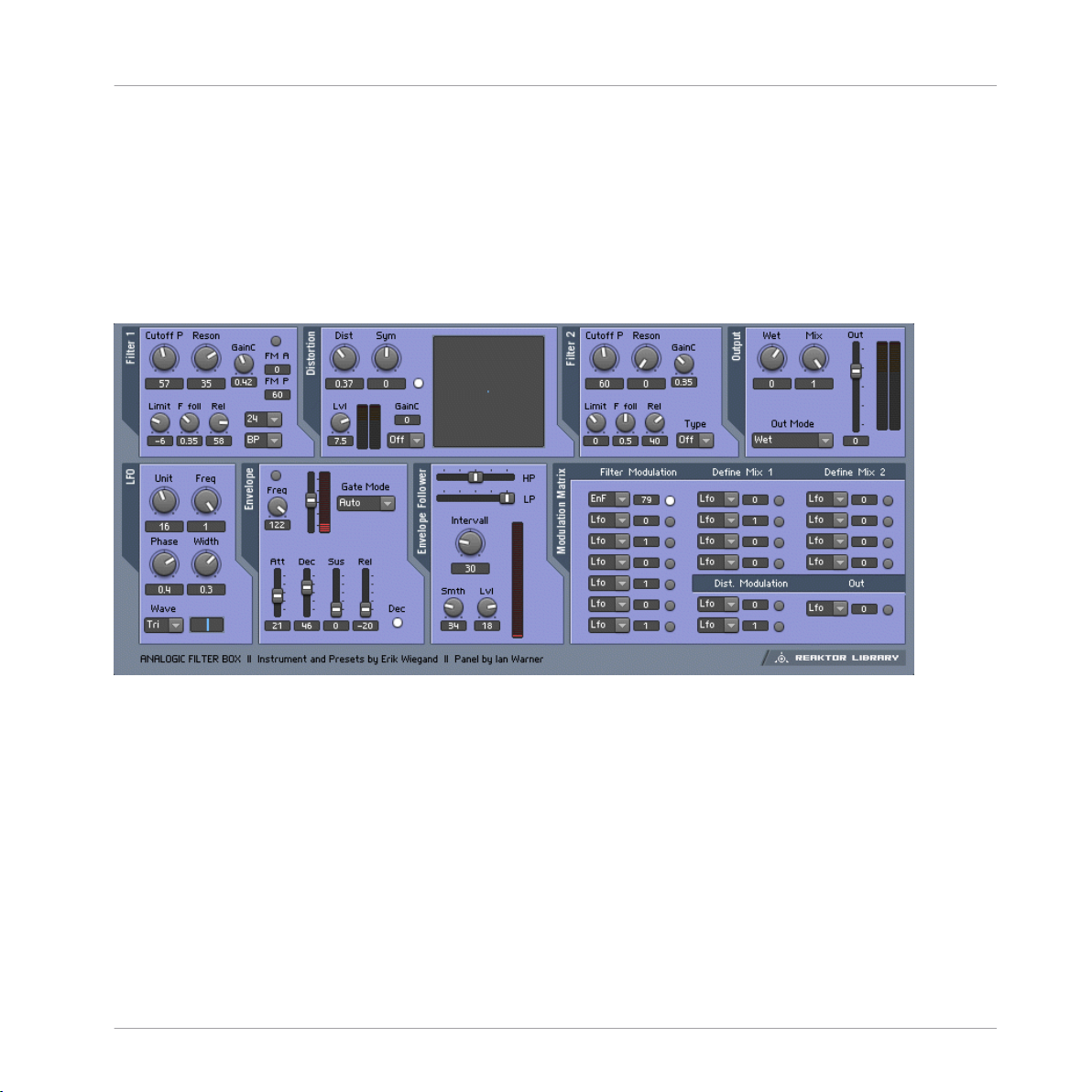
Fig. 1.1 Analogic FIlter Box user interface
1.1.1.1 Introduction
The Analogic Filter Box sandwiches a rich and meaty distortion unit between two hearty
analog-style filters to create a sound-shaping tool for every appetite. Juicy modulation is
also provided on the side: An envelope, LFO, and envelope follower can be freely routed to
the most important filter and distortion parameters. Analogic Filter Box can handle every
thing from fat disco-loop tweaking to full-on mangling of any sound source imaginable.
1.1.1.2
Structure and Signal Flow
The signal is routed from input to Filter 1, to the Distortion, to Filter 2, and then out.
REAKTOR 5.5 - Instrument Reference - 8
Page 9

Both filters offer multiple operation modes. For the first filter, you can choose between
Lowpass, Highpass, Bandpass, Peak EQ, and Notch filters, with a choice of a 12 or 24 dB/
octave slope per filter type. The second filter is designed for shaping the sound after the
distortion, so it offers four different lowpass filters, three bandpass filters, and a bandpass/
lowpass combo. Both filters were very carefully designed to produce warm, analog sounds
even at extreme resonance and cutoff settings.
Beside the normal cutoff frequency control available in both filters, Filter 1 also provides
fast modulation of its frequency by an additional oscillator (which can itself be modulated
by the LFO, envelope, or envelope follower!).
The Distortion section between the two multimode filters also features multiple modes of
operation. While the clipper mode provides a relatively harsh distortion sound and the sat
urator mode results in warm overdrive, the several wrapping modes (marked by the name
of the waveform used for wrapping) produce unique sounds from subtle to extreme.
An additional quantize mode converts the incoming signal into a step waveform, for famili
ar bit-reduction effects to mimic the character of vintage samplers, for instance. A visual
display of the distortion function helps to see what's going on inside.
1.1.1.3 Modulation
Analogic Filter offers six modulation sources (A built-in LFO, envelope follower, enveloper,
MIDI note pitch, modulation wheel, and pitch bend wheel). The modulation sources and
the flexible matrix signal routing system at the bottom of this effect transforms it into an
incredibly powerful machine.
The modulation signal routing system provides a source selector for each parameter to be
modified; among those modifiable parameters are the cutoff frequencies and resonance
settings of both filters and the distortion amount and symmetry control of the distortion
section. In addition to gate information from MIDI note-on events that can even be used to
trigger the filter, you can also use the pitch and mod wheels as modulation sources.
An internal LFO, envelope follower, and auto-trigger envelope can add movement to the
sound without the need any external MIDI controllers. The LFO offers different waveforms
and can also be synchronized to the global tempo or MIDI clock (the small Unit knob
syncs the LFO to MIDI clock and sets the musical note-units that are shown under Freq).
The Envelope Follower calculates its modulation amount from the incoming signal: At high
levels there is a high modulation level, and at low levels it's low. The Interval knob controls
Classics
Effects
REAKTOR 5.5 - Instrument Reference - 9
Page 10

the response time to fast level changes. Use the cutoff controls of the internal highpass
and lowpass filters to select a specific frequency band of the incoming signal to trigger the
envelope follower. The Envelope is a standard attack-decay-sustainrelease envelope gener
ator, triggered by MIDI note on events. However, an additional auto-trigger feature allows it
to be triggered by the incoming audio, settable with the Tresh slider.
It's even possible to combine any two MIDI controllers to make one dependent on the oth
er - for instance, to have the amount of LFO modulation dependent on MIDI pitch. You
can define custom mix modulation combinations in the Define Mix 1 and 2 areas as the
bottom of the instrument.
* You can play a sound through the built-in loop-player, through the realtime audio inputs,
or you can process audio in realtime by using Reaktor as an effect plugin. Please check
your Reaktor or Reaktor Session user's guide for helpful information.
Classics
Effects
REAKTOR 5.5 - Instrument Reference - 10
Page 11
1.1.2 Banaan Electrique
Classics
Effects
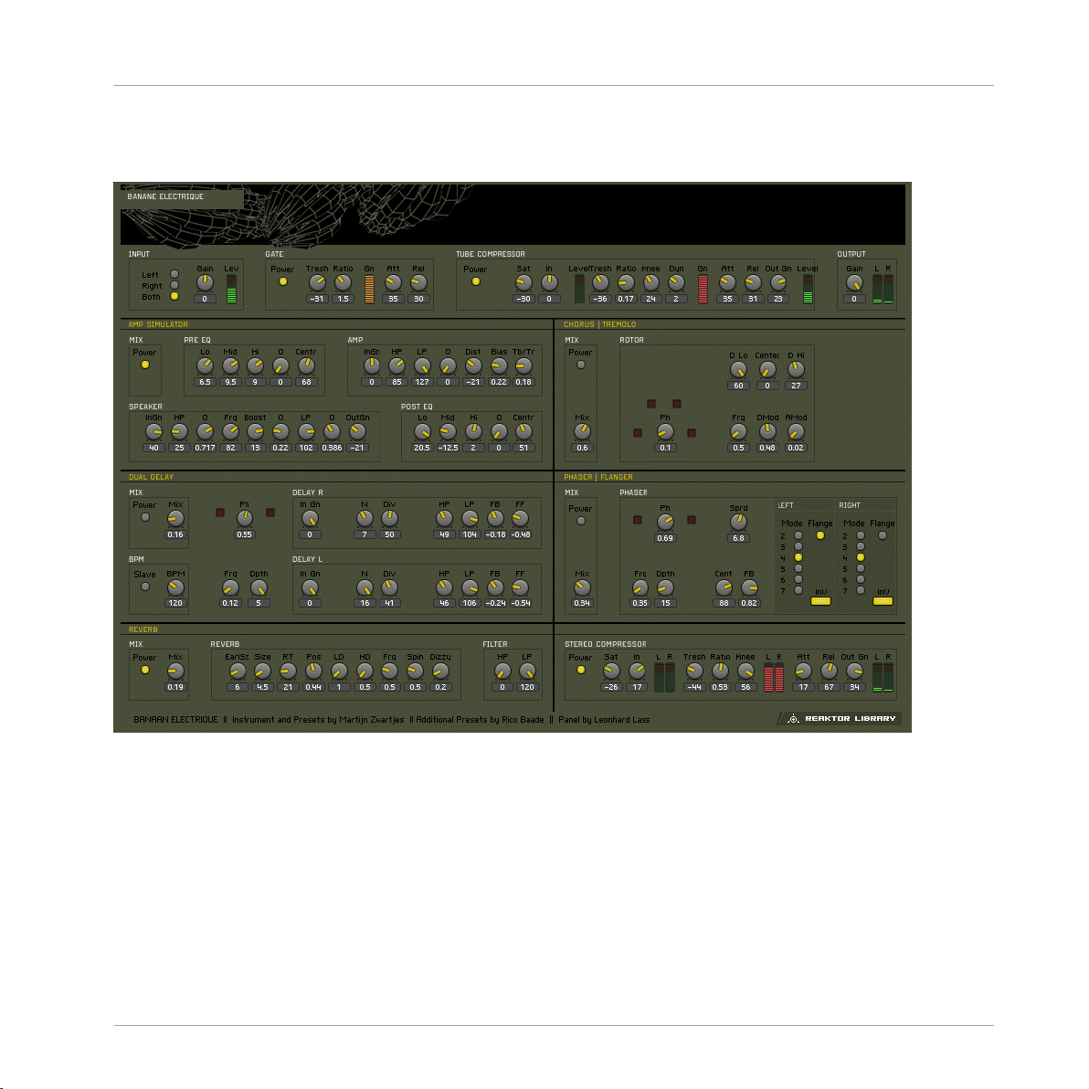
Fig. 1.2 Banaan Electrique user interface
1.1.2.1 Introduction
Banaan Electrique is a sophisticated guitar and bass amp simulator with built in effects.
It's like having a pedal board full of vintage pedals and a vintage amp, with the added ad
vantages of not needing to cable anything together or risk electrocuting yourself by running
too much current through the amp. You can still get shocked by its lush sound, however.
Naturally, Banaan is happy to eat whatever types of sounds you feed it, whether they're vo
cals, drum loops, synths, or scallops.
REAKTOR 5.5 - Instrument Reference - 11
Page 12
1.1.2.2 Getting Started
Banaan Electrique was designed to be so easy that even guitar players can use it! Just play
some audio through it and let a rip.* Check out the presets to see the variety of tones that
Banaan can achieve.
1.1.2.3 Structure and Signal Flow
The audio runs through Banaan Electrique linearly:
Input > mono gate > 3-band EQ > Compressor 1 > Amp Simulator > Phaser > Rotor > Du
al Delay > Reverb > Compressor 2
The incoming signal is converted to mono, amplified, gated, equalized and compressed to
control the input's amplitude level and to enhance those sounds wanted to be in the re
cording, getting rid of any unwanted noise. Then, a guitar amplifier is simulated, including
distortion, overdrive and filtering. Its output signal is sent to a rotor module, placing the
mono sound in the stereo field dynamically. This signal is then routed to a phaser effect
and, afterwards, to a stereo echo unit whose delay times can be synced to master tempo or
MIDI clock. A high-quality reverb enhances the spatial sound once more, feeding its out
put into the final compressor.
Not all modules have to be active at the same time - in fact, it's a good idea to turn off any
modules that you're not using to save CPU. You can turn modules on and off with their
respective Power buttons.
* You can play a sound through the built-in loop-player, through the realtime audio inputs,
or you can process audio in realtime by using Reaktor as an effect plugin. Please check
your Reaktor or Reaktor Session user's guide for helpful information.
Classics
Effects
1.1.3 Classic Vocoder
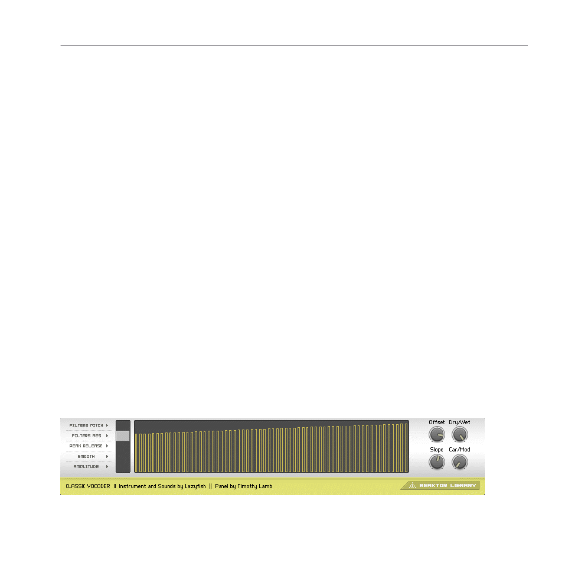
Fig. 1.3 Classic Vocoder user interface
REAKTOR 5.5 - Instrument Reference - 12
Page 13

1.1.3.1 Introduction
The Classic Vocoder was designed to faithfully emulate the well-known tones of singing ro
bots made popular in the seventies. The instrument combines a vocoding engine, a vin
tage-type synthesizer, and a four-band dynamics processor for a warm, smooth sound.
1.1.3.2 Quick Start
The audio input is vocoded with the built-in synthesizer. Play some audio into the vocod
er.* You don't have to sing into it - the Classic Vocoder also gives great results with drum
loops or other sounds.
1.1.3.3 Structure and Signal Flow
Audio input 1 is the modulator, and is vocoded with the Classic 2-VCO synth, which is the
carrier. The entire signal flow is mono. If you are using a stereo signal, only the left chan
nel will be used. The output of the vocoder is fed into the four-band normalizer to smoothout the sound and remove any uncomfortable signal peaks that could come with vocal sibi
lants or drum transients.
Classics
Effects
1.1.3.4
The Vocoding Engine
Sonically, Vocoding uses the characteristics of one sound to control another. To achieve
the popular robotic-singing effect, a voice (technically called the modulator) is vocoded
with a constant sound, such as a synth or string sound (the carrier). The frequency content
of the voice is split up into many different bands - the number of bands has an obvious
impact on the sound, with fewer bands leading to more synthetic voices, and higher bands
make the voice easier to understand. You can adjust the number of voices of the vocoder
instrument to change how many bands are used. Up to 128 voices (bands) are possible.
All changes in number of bands are immediately shown in the graphical display.
The amplitude of each frequency band of the voice is linked to the frequency bands in the
string or synth sound. The re-shaped bands of the carrier signal are mixed together, provid
ing the output signal of the vocoder.
If you're interested in vocoding, you may also want to do check out another NI product the VOKATOR. The VOKATOR features vocoding up to 1024 bands, a built in synthesizer
and granular sampler, and many high-end vocoding features. www.ni-vokator.com.
REAKTOR 5.5 - Instrument Reference - 13
Page 14
* You can play a sound through the built-in loop-player, through the realtime audio inputs,
or you can process audio in realtime by using Reaktor as an effect plugin. Please check
your Reaktor or Reaktor Session user's guide for helpful information.
1.1.4 Echomania
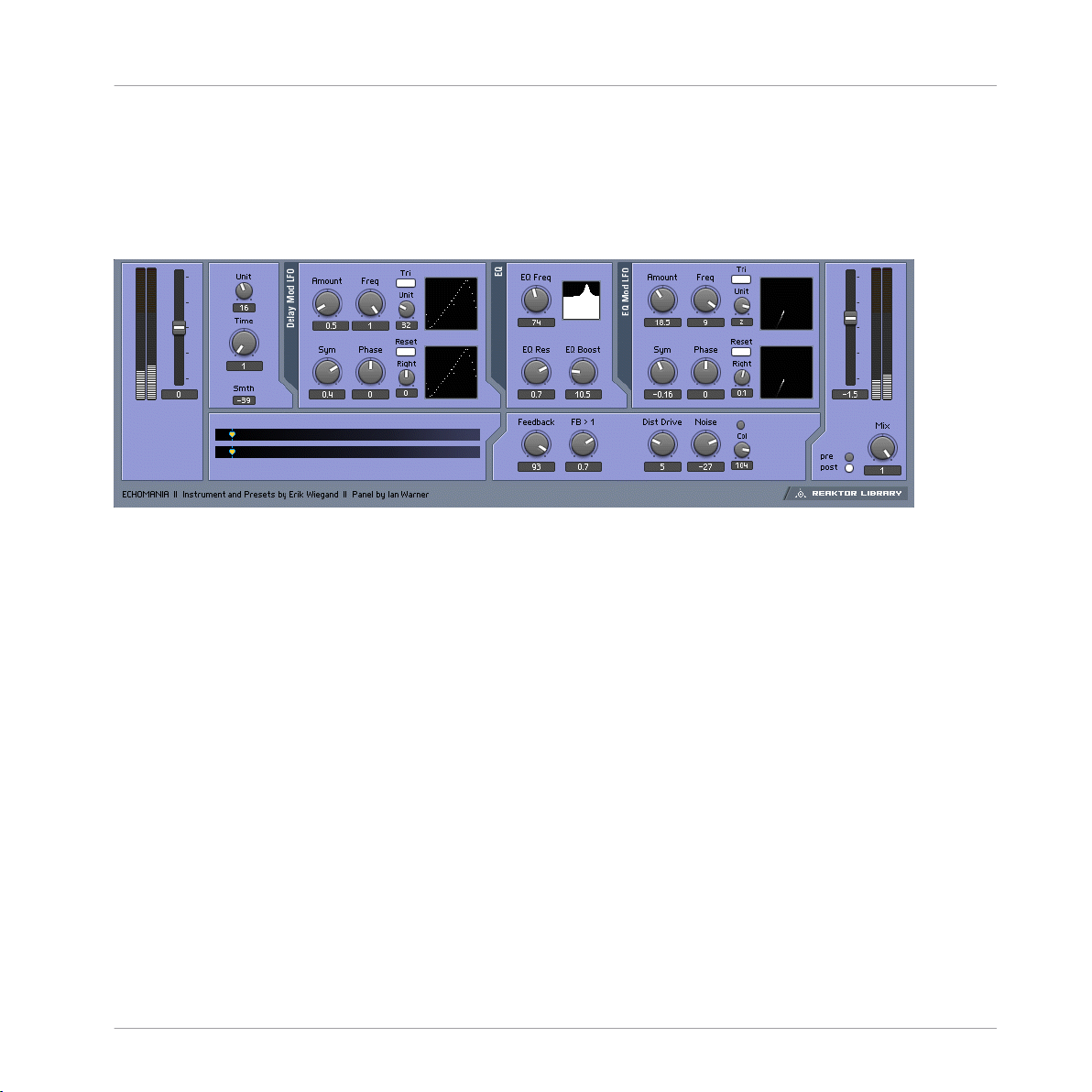
Fig. 1.4 Echomania user interface
1.1.4.1 Introduction
Echomania is an advanced and spectacular-sounding delay box that excels at tight, temposynced rhythms. It includes two LFOs to to modulate the delay time and built-in EQ. The
delay time is handily synced to the global MIDI clock, for creating stretchy rhythmic ef
fects. A drive and noise circuit combined with a feedback offset control recreate vintage
sounds. Get dubbing!
Classics
Effects
1.1.4.2
Quick Start
Play some audio through Echomania.* Flip through the snapshots and discover the gritty
(or crystalline) depths of Tapedelay.
1.1.4.3 Structure and Signal Flow
The delay time is set in 16th note increments, synced to the global MIDI clock. The Unit
and Divisor windows, to the right of the Time control, allow you to fine tune the beat divi
sion and create different rhythmic feels—to be precise, the enumerator divided by the de
nominator scales the delay time fraction.
REAKTOR 5.5 - Instrument Reference - 14
Page 15

There is also an LFO, with blendable sine/triangle/square/slow random waveshapes that is
hardwired to modify delay time. You can set the amount of time modulation with the
Amount knob. The Freq knob controls the rate of the LFO in 16th notes. The Unit knob
divides the speed of the global clock by the Unit amount. For example, if the Unit knob is
set to "6", then the LFO Freq amount will be in 16th notes. The Width control morphs be
tween sine and pulse-like, or, if the Tri button is engaged, triangle and saw tooth wave
shapes. The starting phase of the LFO can be adjusted positively or negatively using the
Phse knob. If you engage the Snc button, the right-side LFO can be phase-offset from the
left side by the amount set with the Right knob. This can create a variety of woozy stereo
spinning and phasing effects.
The EQ module processes the delayed signal. It is essentially a parametric EQ that con
tains an LFO identical to the one in the Delay module. You can create synchronized filter
sweeps, fizzing hi-frequency delay tails, and all manner of dubby effects by boosting and
modulating select frequency bands. The Eq Res control lets you dial in the peak width of
the frequency, while EQ Boost lets you crank it up.
Tapedelay's Feedback module provides an offset control, labeled FB > 1, which boosts and
shapes the feedbacl signal, making it seem to get louder and louder (but without degener
ating into uncontrollable noise).
The Mixer lets you add a tape saturation-like Dist Drive effect and Noise to give everything
that just-pulled-out-of-the-closet feeling.
The Dry Wet section allows you to balance the amount of dry and delayed signal. You can
also use the Tap buttons to select whether the delay tap comes before or after the satura
tion/noise circuit.
* You can play a sound through the built-in loop-player, through the realtime audio inputs,
or you can process audio in realtime by using Reaktor as an effect plugin. Please check
your Reaktor or Reaktor Session user's guide for helpful information.
Classics
Effects
REAKTOR 5.5 - Instrument Reference - 15
Page 16
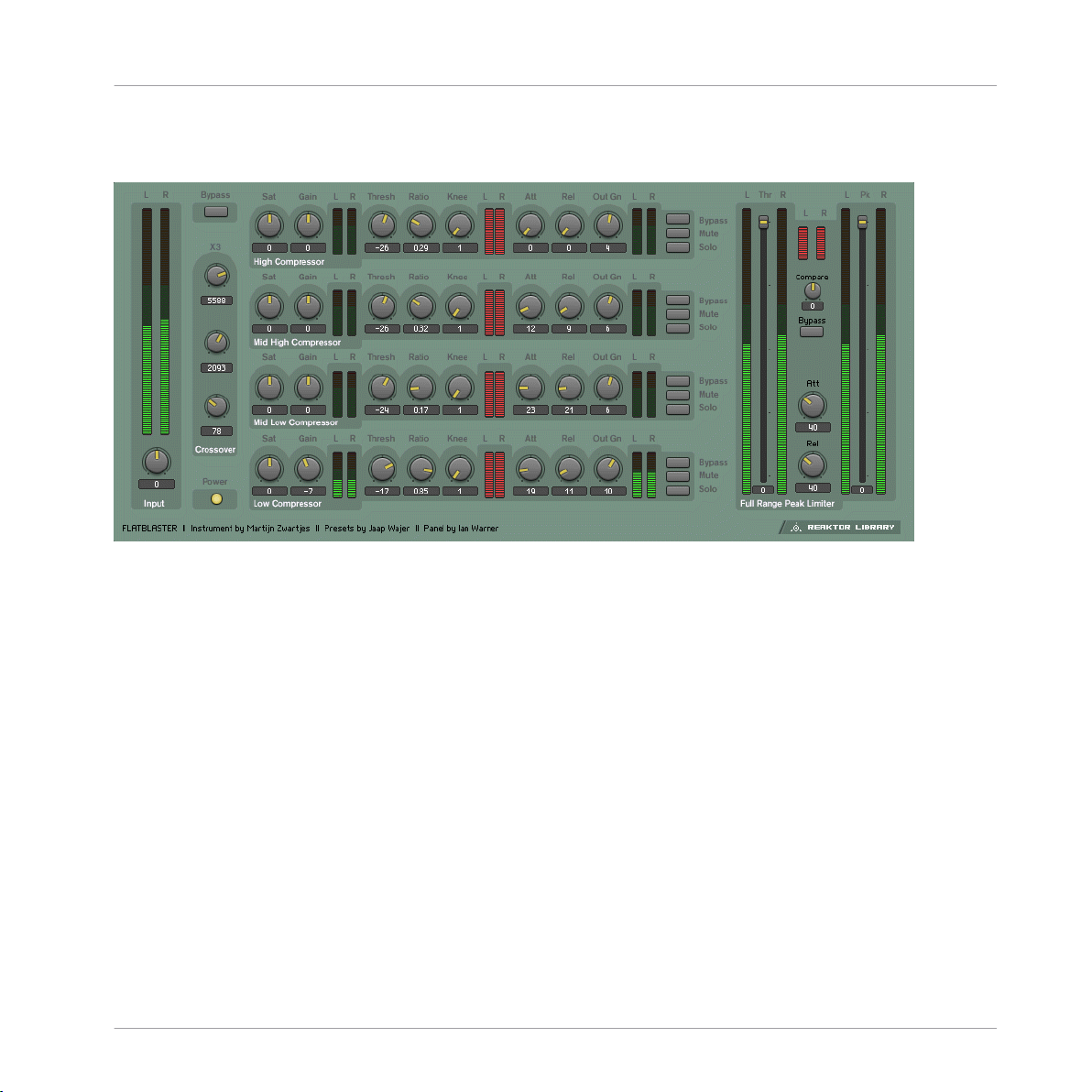
1.1.5 Flatblaster
Fig. 1.5 Flatblaster user interface
Classics
Effects
1.1.5.1 Introduction
Flatblaster is a high-end finalizing and multiband dynamic shaping tool. Flatblaster com
bines four frequency-specific compressors with a full-spectrum peak-limiter. It is an excel
lent final-step mastering plug-in, but it can also be used while mixing since it doesn't in
troduce any delay to the signal. Each of the compressors has a saturator, so you could sat
urate just the upper-mid frequencies, for instance, without muddying the bass. It also
makes an excellent de-esser and sibilant reducer.
1.1.5.2
Quick Start
Even though Flatblaster gives control over many sound-shaping parameters, there's no
need to be intimidated by its complexity. A full range of presets shows off its capabilities
and gives good starting points for tweaking the effect for your sound. Simply play some au
dio through Flatblaster* and step throught the presets. Try experimenting with muting, so
loing, and bypassing each individual band so you can carefully hear what the 'blaster's do
REAKTOR 5.5 - Instrument Reference - 16
Page 17

ing. Be careful when adjusting the saturation of each band! The sound can potentially get
very loud if you don't first reduce the make-up gain (the knob labeled Gain to the right of
the Sat knob).
1.1.5.3 Structure and Signal Flow
The input signal is divided into four bands - the three crossover frequencies are adjustable
independently. Each frequency band is processed by an independent, identical compres
sor. Each band can be muted, soloed, and bypassed (no compression). The signal is sum
med before going through a full-band peak limiter, which can also be independently by
passed. The master bypass for the effect is located to the right of the input meters, above
the crossover settings.
Classics
Effects
1.1.5.4
Frequency-Specific Compressor
Each of the four compressors are absolutely identical. In fact, they have to be! If they
weren't, then unwanted phase shifts could creep in. Each compressor gives control over
saturation, saturation makeup gain, threshold, compression ratio, adjustable knee, attack,
release, and output makeup gain. Note that the Ratio has to be higher than 0 for the com
pressor to have any effect - at a Ration of 1 (maximum), the compressor acts as a limiter.
The red meters show the amount of peak reduction. The Attack and Release knobs control
how the compressor responds to transient signals.
1.1.5.5
Full-Band Peak Limiter
The peak limiter affects the full frequency range of the audio, after each of the four fre
quency bands has been compressed separately. The Threshold slider controls when the
peak limiter will start working. With Threshold at 0, the peak limiter will have no effect.
For mastering, it's recommended to have the Threshold set to around -3 or -4 dB. Severe
Threshold settings will lead to pumping, which may or may not be desirable. The Attack
and Release knobs control how the peak limiter responds to transient signals. The final
Peak slider sets the output level of the signal. When Peak is set to its maximum 0 dB,
then the audio will be as loud as possible. There's really no reason to ever set Peak lower
than this, unless you needed to ensure a certain amount of headroom.
REAKTOR 5.5 - Instrument Reference - 17
Page 18

* You can play a sound through the built-in loop-player, through the realtime audio inputs,
or you can process audio in realtime by using Reaktor as an effect plugin. Please check
your Reaktor or Reaktor Session user's guide for helpful information.
1.1.6 Fusion Reflections
Classics
Effects
Fig. 1.6 Fusion Reflections user interface
1.1.6.1 Introduction
Fusion Reflections is a delay-based effect that can create early reflections, shimmering
choruses, fluttering delays, and even ambient reverbs. Two distinct diffusion engines are
chained together to create an extremely wide range of effects. Each finely-tuned diffusion
engine consists of four stereo modulation delays and an innovative graphical display that
shows the actual delay time for each delay. Just five controls control the core parameters
of each diffusion engine.
REAKTOR 5.5 - Instrument Reference - 18
Page 19

1.1.6.2 Quick Start
Play some audio through the effect* and select Preset 1 Long Decay Echo. This preset on
ly uses the Chor Fusion diffusion engine. Play with the Diff Dly knob - note how the graph
ic display constantly updates to show you the current delay times. Stop the incoming au
dio to listen to the sound's decay. Play with Dly Mod and Speed to see what effect they
have on the sound and the graphic. Be sure to check out all the other presets to see how
versatile this effect can be!
Classics
Effects
1.1.6.3
Structure and Signal Flow
The sound passes through two diffusion engines serially. It's important to note that the two
engines are similar but not identical - they each offer unique sound-shaping capabilities.
The first diffuser, Chor Fusion, is the simpler of the two and is designed for early reflec
tions, choruses, and atmosphere. If offers a high and low shelf EQ, with a graphical dis
play of the EQ curve. The second diffusion engine, Echo Fusion, adds a feedback delay
before the diffusion delays. The diffusion delays in the Chor and Echo engines are identi
cal. Echo Fusion is perfectly tailored to late reflections, long delays, and long reverbs. A
highpass filter (HP) cuts the low frequencies after the delay and before the diffusors, while
a lowpass filter (LP) can reduce the brightness at the last step. The input to the Echo Fu
sion engine can be switched between the dry signal, and the signal coming out of Chor
Fusion.
In the Mixer section the signals of Chor Fusion> and Echo Fusion are combined and mixed
with the dry signal. Each section can also be switched on or off to save CPU.
1.1.6.4 Diffusion Delays
Both the Chor and Echo Fusion engines contain identical diffusion delays. As mentioned
above, Echo fusion adds a single feeback delay before the diffusion delays, but the opera
tion of the diffusion delay section is identical per effect. Each diffusion delay consists of
four stereo modulation delays and an innovative graphical display that shows the actual
delay time of each delay. The main delay time is controlled by the Diff Dly knob. The Dly
Mod knob controls the amount of delay time modulation by the internal LFOs. Speed con
trols the speed of the LFO. Stereo sets the stereo spread of the delays, and Diffusion sets
REAKTOR 5.5 - Instrument Reference - 19
Page 20
the inaccuracy of the delay times. The sum effect of these five knobs is graphically shown
in the display underneath, where each "pendulum" represents the delay time of a single
delay.
* You can play a sound through the built-in loop-player, through the realtime audio inputs,
or you can process audio in realtime by using Reaktor as an effect plugin. Please check
your Reaktor or Reaktor Session user's guide for helpful information.
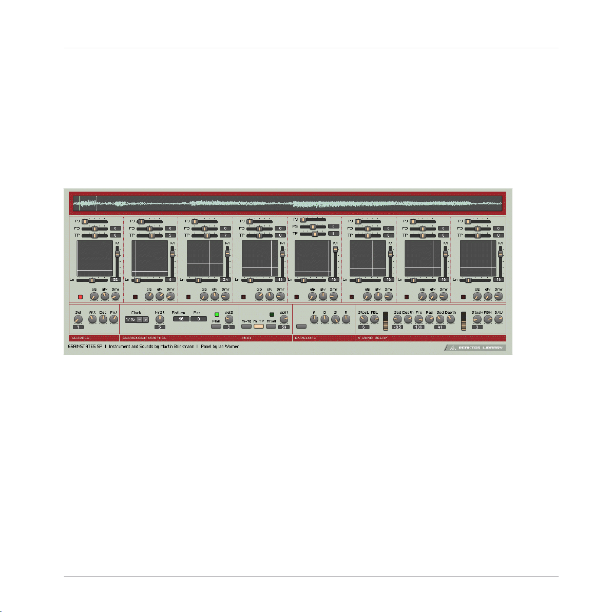
1.1.7 Grainstates FX
Classics
Effects
Fig. 1.7 Grainstates FX user interface
1.1.7.1 Introduction
Grainstates is a granular texture maker that works wonders for creating dense, breathing
atmospheres. Taking advantage of Reaktor 4's grain cloud delay module, GrainStates lets
you create granular soundscapes in realtime. You can even freeze the live audio - imagine
playing a guitar into Grainstates, freezing the audio, then playing a counterpoint to the
granular texture. Eight scenes - each scene storing information about grain size, density,
pitch, pitch spread, and more - are sequentially recalled in sync with the master tempo. A
dual-frequency delay adds depth to the sound by letting you specify independent delay
and feedback times for the high and low frequencies.
REAKTOR 5.5 - Instrument Reference - 20
Page 21

Grainstates consists of two ensembles: GrainStatesFX and GrainStatesSP. GrainStatesFX is
an effect using the grain cloud delay that works on live input, while GrainStatesSP is cen
tered around the grain cloud sampler module. The FX ensemble has the advantages that
you can easily process audio without loading anything into a sampler and you can freeze
the incoming audio stream - great for live performance! Since the sound passes through
the ensemble, however, there's no way to save the sound data with the preset. GrainSta
tesSP stores the sample with the preset so it can easily be recalled at a later time, but you
must first load your sound into the grain cloud sampler.
Classics
Effects
1.1.7.2
Quick Start
GrainStates FX: Start the system clock and run some audio through the ensemble.* You'll
notice a graphical representation of the sound "marching through" the granular buffer. To
freeze the buffer, press the Freeze button to the left of this graphical display. If you stop
the system clock, the sound will continue, but the scenes won't advance.
GrainStatesSP: Start the system clock and step through the presets. If you stop the system
clock, the sound will continue, but the scenes won't advance.
1.1.7.3
Structure and Signal Flow
At the heart of GrainStates is the granular grain cloud module. GrainStatesFX is based on
two (for true stereo operation) grain cloud delay modules, while GrainStatesSP is based on
a single grain cloud sampler module. Both the grain cloud delay and grain cloud sampler
have identical controls, with the grain cloud delay adding the ability to freeze the sound.
All of GrainState's controls (with the exception of the 2Band Delay) are used to control the
grain cloud.
A master sequencer runs through eight scenes are run through sequentially, with each
scene providing control over various granular parameters. Every scene can have its own
length, settable by the Ln slider, whose units are set in the Seq Control macro. You can
also set the total number of scenes (NrSt), and if you want to disable the scene sequencer
simply click on "man" and you can select a scene manually with the SelS knob.
Each scene provide control over pitch jitter (PJ: amount of pitch randomization, in semi
tones), pitch shift (PS: in semitones), transposition (TP: in semitones), volume (Lvl), and
an XY panel lets you set two parameters graphically at once: The horizontal axis sets the
REAKTOR 5.5 - Instrument Reference - 21
Page 22

start position of the grain (relative to the graphical display on top of the internal buffer),
while the vertical axis sets the length of the grain. Three additional knobs provide control
over the smoothness of scene transitions, and the grain density smear (Smr).
GrainStatesFX only: The sound is filtered by the Filtor macro with independently adjusta
bly highpass (HP) and lowpass (LP) frequencies. Res adjusts the resonance of both filters,
while Byps disables the filter.
The output of the filters is fed back into the grain cloud delay, with feedback independent
ly adjustable per scene with the FB slider to the right of the XY control. The feedback is
only active then the grain cloud delay is not frozen. When the grain cloud delay is frozen,
it ignores any signal to its inputs.
The sound then passes through a 2Band Delay, which gives independent control over delay
time in sixteenth notes (StepsL and StepsH), feedback (FBL and FBH), and a filter-modu
lating LFO. The cutoff and resonance of the filter that splits the two bands is determined
by the Frq and Res knobs. Finally, a D/W knob sets the mix level. To bypass the filter, sim
ply set D/W to zero.
1.1.7.4 Additional Controls
Global Params. In the global parameters, you can set the global attack and decay of the
grains, and the amount of pan jitter (stereo randomization). In GrainStatesSP, this is also
where you select the active sample, with Sel.
GrainStatesFX only: the Move macro controls a built-in ramp oscillator that controls the
delay time. The Steady knob is the amount of delay modulation - when at zero, then the
ramp oscillator does not change the delay time.
Classics
Effects
1.1.7.5
MIDI Control
In addition to automated sequencer control, GrainStates also lets perform with a MIDI key
board. In the MIDI macro, you have control over the MIDI functionality. If "m TP" is acti
vated, then MIDI notes will pitch the sound, like in a conventional sampler. In Grain
States, however, all notes are the same length, regardless of pitch. When "mSel" is active,
each scene is mapped onto a note pitch between 48 and 59 (only the white keys of a key
board); by pressing one of the notes the respective scene is selected. With the Split knob
REAKTOR 5.5 - Instrument Reference - 22
Page 23
you can specify another keyrange that recalls scenes. "m-tg" toggles MIDI triggering of
sound on and off. GrainStatesFX only: "m-frz" lets you toggle the freeze effect on/off via
MIDI.
GrainStatesSP only: If you play GrainStatesSP over MIDI, you can activate the envelope
(env macro) to also control the amplitude of the sound with MIDI, according to the set
tings of the envelope.
* You can play a sound through the built-in loop-player, through the realtime audio inputs,
or you can process audio in realtime by using Reaktor as an effect plugin. Please check
your Reaktor or Reaktor Session user's guide for helpful information.
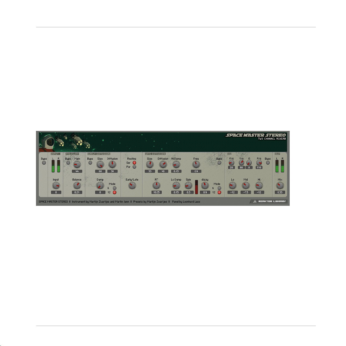
1.1.8 SpaceMaster
Classics
Effects
Fig. 1.8 Space Master 1 user interface
1.1.8.1 Introduction
The SpaceMaster series of reverbs breaks new ground in reverb modelers for Reaktor.
Spacemaster uses two different Diffusion modules to achieve stunningly convincing room
sounds. And to fully exploit SpaceMaster's lushness, there are three versions - SpaceMas
ter stereo, SpaceMaster Quad, and SpaceMaster 5.1 Surround.
Quick Start
To really get a feel for the kinds of lush atmospherics SpaceMaster can provide, it's a good
idea to either hook a beat looper or external sound source up to it, or, to utilize it in plugin
mode in your favorite audio sequencer. Stepping through the presets should give you a
REAKTOR 5.5 - Instrument Reference - 23
Page 24

good impression of the kinds of real and imaginary spaces SpaceMaster can emulate. Ad
justing the controls of the Early and Late Diffusion modules will have the most effect on
the sound, and will give you an idea of how the two main components interact in creating
ambiences - especially since they can be arranged in serial or parallel signal paths.
Structure and Signal Flow
This guide will use the Stereo SpaceMaster ensemble to outline the various controls for
shaping the reverb signal, since most of them are the same among the three types of
SpaceMasters. Read on below to learn about the specifics of the Quad and Surround fla
vors of SpaceMaster reverb.
Classics
Effects
REAKTOR 5.5 - Instrument Reference - 24
Page 25
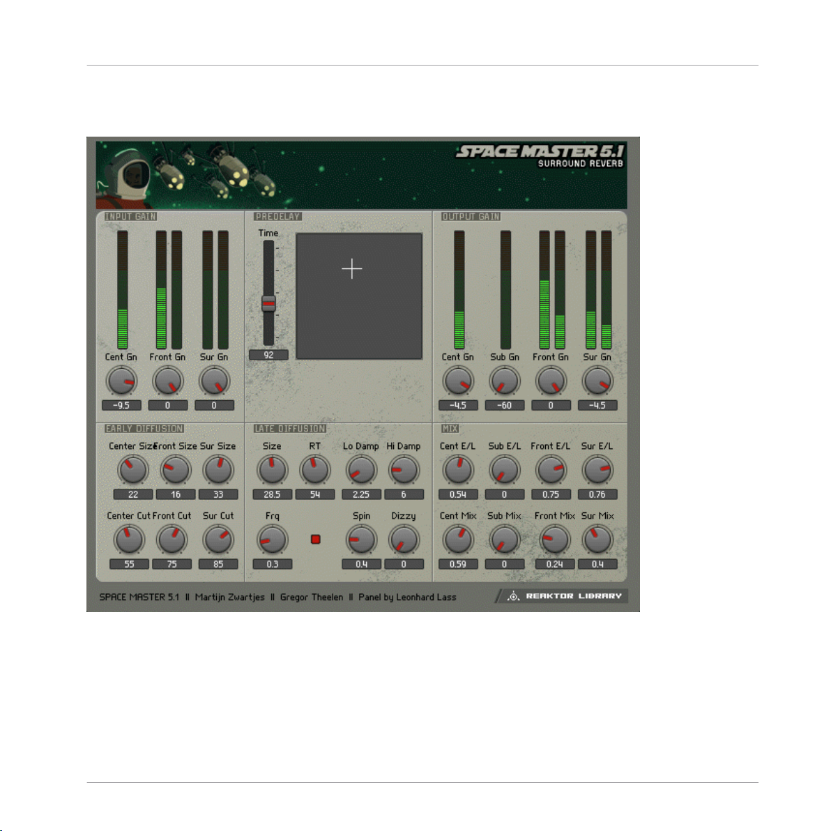
1.1.8.2 SpaceMaster 5.1 Surround
Classics
Effects
Fig. 1.9 Space Master 5.1 Surround
The Surround version of SpaceMaster is effectively the same as the Quad version
(
↑1.1.8.3, SpaceMaster Quad), except that it adds a Center channel. The PreDelay XY pad
adds control for the center channel. SpaceMaster Surround also adds an Output Gain sec
tion that allows you to use precise metering to control the relative volumes of the Center,
Sub, Front, and Surround reverb signals. The balance of Early/Late signal can also be ad
REAKTOR 5.5 - Instrument Reference - 25
Page 26
justed for each channel using the Mix module, which has familiar controls for wet/dry lev
els. Finally, SpaceMaster Surround does not include the EQ module found in the Stereo
and Quad versions.
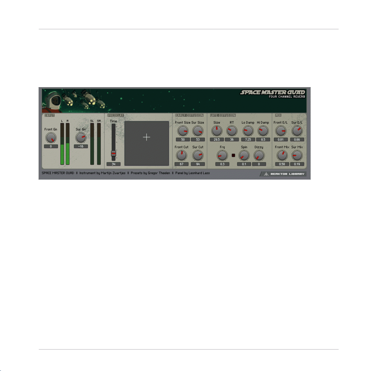
1.1.8.3 SpaceMaster Quad
Fig. 1.10 Space Master Quad user interface
Classics
Effects
The SpaceMaster Quad ensemble works in the same way as the stereo version (↑1.1.8.4,
SpaceMaster Stereo
), but it splits the reverb signal into four discrete outputs for using in a
four-speaker system. The signal for the forward speakers is referred to as the Front signal,
while the signal for the rear speakers is referred to as the Surround, or Sur, signal. In the
Input section, you can adjust the gain for Front and Sur signals to determine how much
signal sources reaches each signal chain.
The PreDelay section is simplified from its stereo brother by use of an XY pad to finely ad
just Front and Surround L/R offset. The overall PreDelay time can be controlled by the
Time fader.
The Early Diffusion section is also simplified, offering only Size and high frequency Cut
controls for both Front and Surround diffusion signals.
The Late Diffusion module is effectively the same as the one found in SpaceMaster Ster
eo. Refer to the description above the learn how it works.
The Mix section allows you to balance the Front and Surround signal amount and to adjust
the wet/dry mix for each.
REAKTOR 5.5 - Instrument Reference - 26
Page 27

1.1.8.4 SpaceMaster Stereo
SpaceMaster Stereo is composed of a PreDelay module, an Early Diffusion module, a Late
Diffusion module, and a post EQ. The Diffusion modules can be combined together to cre
ate a complex impression of space. By adjusting the balance of the Early and Late diffu
sion modules, you can precisely move the origin of the reflections from near to far (or front
to back), making SpaceMaster perfect for Surround mixing situations in which a truly
room-filling reverb can be created.
The Input section, at the fat left, allows you to trim the input gain to avoid overloading the
audio signal. The input is next processed by the PreDelay. Use this to add an initial delay
to the wet signal. You can also use the L/R offset knob to add some perceived stereo width
by altering the delay time of the left-side single delay module. You can bypass the PreDe
lay with the Byps button.
Next in the signal path, the Early Diffusion module, which is actually a series of up to 12
diffusion delays, provides the near reverb processing. The Size control allows you to deter
mine the range of space that the close reflections will be generated by. It changes delay
time in milliseconds. The Diffusion knob lets you adjust the density of the reverb signal.
To further adjust the reverb depth of the Early Diffusion module, the Mode switch allows
you to select 6 or 12 diffusion modules. Watch your CPU load carefully to make sure your
computer can handle the strain of processing with 12 (or 24) diffusion modules. The
Damp knob controls the frequency of a 1-pole low pass filter for attenuating high frequen
cies. As in the PreDelay section, clicking the Byps button will take the Early Diffusion
module out of the signal path.
The Routing switch, located between the Early and Late Diffusion modules, lets you deter
mine how the input signal will be routed through the two modules. The Ser button engages
Serial mode, where the Early Diffusion module is simply routed directly into the Late mod
ule. The Par switch engages Parallel mode, allowing the Early and Late modules to main
tain separate signal paths, until they are mixed at the EQ module. You can also use the
Early/Late knob to balance the amount of early and late reverb signal. This is a great way
to change the perception of location within a space, by shifting between the early and late
reverb sounds (to make it seem like a sound is moving around inside of the "room").
Classics
Effects
REAKTOR 5.5 - Instrument Reference - 27
Page 28
The Late Diffusion module provides the capabilities for creating a larger and more richly
defined space. The Size and Diffusion knobs work the same way as those in the Early sec
tion, but there a few new options. The RT knob controls a feedback loop, allowing you to
stretch out the apparent reverb time, or the time it takes for the echo to return to the point
of origin. There are also controls for high and low shelving EQs, called Hi Damp and Lo
Damp, respectively, that allow you to shape the frequency range of the reverb signal. You
can modulate the delay time and apparent position of the reverb signal by using the modu
lation controls. The Spin knob adjusts the amplitude of a sine wave LFO, while the Dizzy
knob controls amplitude for a Slow Random LFO. You can create complex modulations by
adjusting the balance of sine wave and random LFOs. The Freq knob controls the rate of
both LFOs together. As in the Early section, 6 or 12 diffusion modules can be selected
with the Mode switch. This section can also be bypassed with the Byps button.
Both the Early and Late Diffusion sections feed into the EQ. The EQ consists of stereo low
shelf, parametric, and high shelf filters. Starting at the left, the Lo knob lets you control
attenuation or boost of the low frequency set with the Frq immediately above. The Mid
knob controls the parametric EQ band. The Frq and Q knobs above it let you adjust the
frequency and bandwidth of the parametric. The Hi knob controls attenuation of the high
shelf filter. Use the Frq immediately above the Hi knob to adjust the frequency. As in the
other modules, the EQ can be taken offline with the Byps button.
Finally, the mixture of wet and dry signal can be adjusted to taste with the Mix knob in the
output section.
Classics
Effects
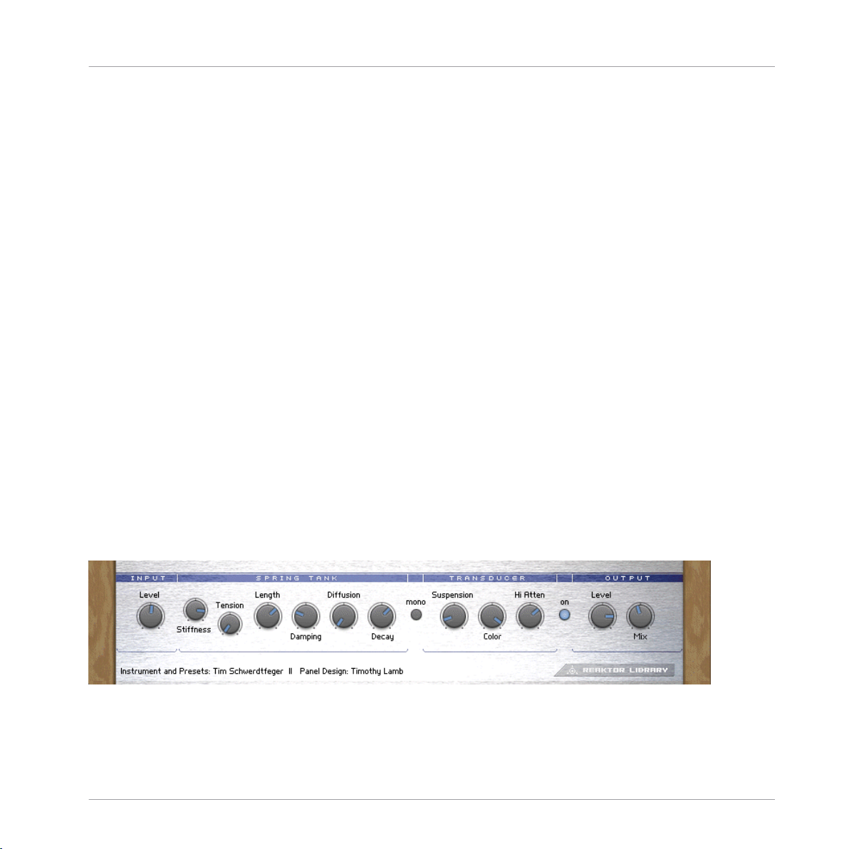
1.1.9
Fig. 1.11 Spring Tank user interface
Spring Tank
REAKTOR 5.5 - Instrument Reference - 28
Page 29

1.1.9.1 Introduction
Spring Tank pays homage to the trashy, unrealistic spring reverbs of the past. While Spring
Tank isn't exactly a physical model of a spring, it goes a long way toward recreating the
spring reverb characteristics: dull, transducer-saturated, and boingy, with the familiar non
linear resonating decay.
1.1.9.2 Quick Start
Spring Tank is meant to be an experimental effect, rather than a realistic one, play some
audio through the effect* and experiment! It allows control over the elements of the
"spring's" morphology, so you can design your own spring.
1.1.9.3 Structure and Signal Flow
The input source is amplified or attenuated with the Level knob at the far left of the in
strument. High levels here can introduce transducer saturation (which is not such a bad
thing). The signal is then fed into the spring tank. Here, you can adjust the spring's physi
cal characteristics. The Damp knob sets high frequency damping for the spring. Turning
the knob clockwise increases the damping. Stiffness, which mimics the flexibility of the
spring, gives brighter, more resonant sounds at higher settings. The Shape knob allows you
to crossfade between a round spring shape to the left, and a rectangular one to the right.
The round shape emphasized a ringing sound, while the rectangular shape creates less
ringing but a more diffuse sound.
The Thickness of the spring determines the virtual diameter of spring winding, and there
fore the overall length of the spring. Longer spring settings result in reduced brightness.
The Length setting reflects global length. Turn this up to increase the shattering decay
sounds. The Decay knob changes the length of the decays. It alters the amount of feed
back in the system.
Switching the Mono button off engages an additional short delay in one channel, resulting
in the simulation of stereo.
The Suspension section allows you to mimic the type of spring suspension in the system.
When you turn the knob to the left, you increase the "softness" of the suspension material.
This will lengthen the decay rate of lower frequencies. What this is actually doing is ad
Classics
Effects
REAKTOR 5.5 - Instrument Reference - 29
Page 30
justing the cutoff of a high pass filter in the feedback loop. Suspension will therefore also
have an effect on the sound of the Transducer saturation. The Color knob lets you adjust a
global tone control. Turning this clockwise results in a brighter sound, and vice versa.
The Level knob controls the volume of the wet signal. You can adjust the balance of wet
signal to dry signal with the Mix knob. Finally, you can bypass the effect all together by
clicking the On button.
* You can play a sound through the built-in loop-player, through the realtime audio inputs,
or you can process audio in realtime by using Reaktor as an effect plugin. Please check
your Reaktor or Reaktor Session user's guide for helpful information.
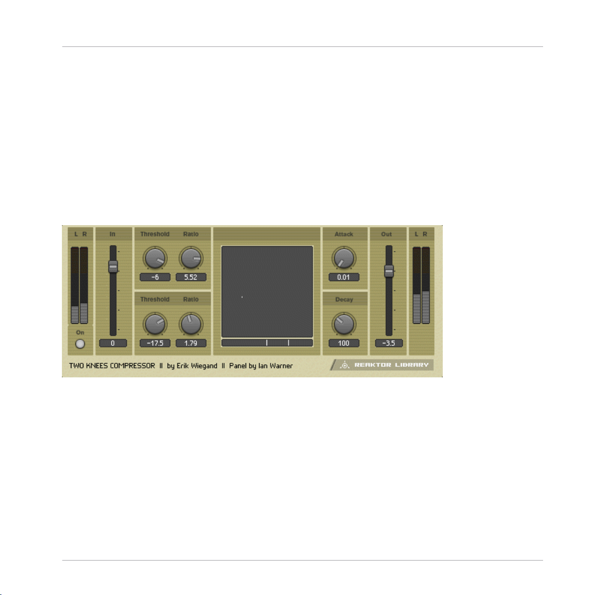
1.1.10 Two Knees Compressor
Classics
Effects
Fig. 1.12 Two Knees Compressor user interface
1.1.10.1 Introduction
Two Knees Compressor is a simple compressor with an important quirk it has two separate
adjustable thresholds and ratio controls. 2-Knees Compressor can perform as a precisely
accurate compressor/limiter, a distorting sound shaper, a transient modifier, or anything in
between. It includes a compression curve display to show the relationship between the
amplitude of the input signal and the amplitude of the processed signal.
REAKTOR 5.5 - Instrument Reference - 30
Page 31

1.1.10.2 Quick Start
Play some audio through Two Knees*. Try to input a beat and run through the snapshots
to hear a clear example of how it can alter transients.
1.1.10.3 Structure and Signal Flow
Set the input level with the In fader to achieve 0 dB on the input meters. The top set of
Threshold and Ratio knobs refer to the upper threshold of the compressor. The upper com
pression ration is applied if the amplitude of the input signal exceeds the upper threshold.
The ratio determines how many dB the signal must exceed the threshold to result in a 1dB
increase of the output signal. The lower threshold and ration controls are directly beneath
the upper controls. The lower compression ratio is applied if the amplitude signal is within
the range between the upper and lower thresholds.
The Thresh setting shows up on the display just below the compression curve display. The
upper threshold setting will be on the right side of the display and the lower will appear on
the left. This will help you to dial in your threshold range to get particular hard-knee or
soft-knee sounds. Try adjusting the degree of separation between the upper and lower
thresholds and watching the display to see where the compression crosses from sharp-an
gled hard-knee style to rounded soft-knee.
You can adjust the attack time of the compression in milliseconds using the Attack knob.
The Attack setting determines how fast the compressor responds to (turns down, basically)
a signal that exceeds the threshold limits. Slower attack times tend to let more transients
through. The Release knob lets you set how fast the compressor returns to unity gain (or
zero gain) after falling below the threshold limits. You can manipulate the apparent sus
tain time of some sounds with the Threshold adjustment. Long release times tend to
sound more "natural".
Finally, you can make up for gain reduction after compression by adjusting the Out level.
You can also bypass the compressor by turning off the On switch.
* You can play a sound through the built-in loop-player, through the realtime audio inputs,
or you can process audio in realtime by using Reaktor as an effect plugin. Please check
your Reaktor or Reaktor Session user's guide for helpful information.
Classics
Effects
REAKTOR 5.5 - Instrument Reference - 31
Page 32

1.2 Grooveboxes
1.2.1 GoBox
Classics
Grooveboxes
Fig. 1.13 GoBox user interface
1.2.1.1 Introduction
GoBox is a monophonic sampler specially designed for live use. It features some hands
controls for altering patterns, sounds, and modulations during a performance. A series of
event tables form an easy to use interface that make it easy to see what's going on. Apart
from sample modulation capabilities, there are a tempo-synced Filter Delay, a Mod Delay,
and the Sync-ro-nizer module, which can play patterns of short samples metronomically.
REAKTOR 5.5 - Instrument Reference - 32
Page 33

1.2.1.2 Quick Start
Start the system clock and check out some of the presets. As the sequence plays, try ad
justing some of the sample modulation parameters, like Attack, Loop, or Octave. Try out
the tap 'n' drag slider located under the waveform display to manually modulate a sample
as it plays.
1.2.1.3 Structure and Signal Flow
GoBox is a sequenced sampler of an unusual sort. Instead of playing loops it triggers one
short sample at a time, monophonically. This can lead to bizarre junky/funky beats, uncer
tain patterings, and minimalist dance floor workouts. Two event tables sequence the pitch
and trigger state of each of four sampler modules.
The Start point, Octave, and Pan position can be set using event tables for each of the
samples. Start determines where in the sample the loop will start, while Octave tunes each
sample in octave steps. Pan lets you position the sample in the stereo field.
The samples have their amplitudes contoured by four ADR envelopes. The tables for these
are located in the second row in the sample modulation area. Overall volume for each of
the four sample channels can be set using the Gain control. The Reduktor performs sam
ple rate-and bit depth-reduction for each sample. Use this to add some dirt to your sam
ples or to reduce them to staticy noise. All of the envelopes can be scaled, that is, general
ly shortened or lengthened in time, with the Scale button below the Morph XY pad. Use
the Scale control to tighten up beats or to make beats seem louder by increasing the over
all decay and release times.
The Loop table controls how much of the sample loops as it is triggered beginning at the
point set by the Start control. Odd loop lengths can create stuttering and staccato rhythm
effects.
After being contoured, the samples can be fed into the effects modules in differing
amounts with the Filter Delay and the Mod Delay tables. The Filter Delay's delay time is
automatically synchronized to the system clock in 16th notes. Filter frequency and reso
nance can be adjusted with the XY pad. Use the Envelope knob to modulate filter cutoff
with the sample envelope.
A Mod Delay for chorus and reverb-like effects accompanies the Filter Delay. Two xy pads
let you adjust the Time/Feedback balance and the Amount/Rate of delay time modulation.
Classics
Grooveboxes
REAKTOR 5.5 - Instrument Reference - 33
Page 34

The Sync-ro-nizer module sits on the end of the signal chain after the effects. It offers two
synced sample players for generating simple, metronomic beats to help keep everything in
line and lock down your rhythms. Select a sample using the Select knob. The sample pitch
can be adjusted using the Tune control. The Style knob selects a timing value on a preset
sample trigger grid (i.e. 1/8th notes, 1/16th notes, 1/32nd notes, etc). You can turn each
sample on and off using the mute buttons below the level meters.
Classics
Grooveboxes
1.2.1.4
The Sequencer
Event tables are used to sequence the pitch and trigger values for the sample loop mod
ule. The Pitch table sets the pitch for each step of a 16th note grid. The Trigger table se
lects which of the four possible samples plays on each step of the grid. You can place a
rest into a sequence by selecting no sample for that point on the grid. As the clock runs,
the sample selections play on the steps they are set for. A Transpose fader to the right of
the Pitch and Trigger tables shifts the pitch sequence up or down.
You can select a sample for each of the four samplers using the Choose table. Load new
sample maps into the sampler module by double clicking on the waveform display. You
can label your sample categories by double clicking on the text field to the left of the
Choose table and typing in the corresponding areas.
The clock controls for running and modulating the sequence all appear in the upper left
hand corner. You can use the Scene knob to store sequencer and sample settings inde
pendently of the snapshot menu. You can store up to eight scenes. The Reset selector al
lows you to determine when the sequencer will reset its start point to the step chosen with
the Start selector. From top to bottom, the sequence can be set to: reset every bar, reset
every 2nd bar, reset every fourth bar, or no reset at all. The Grid selector, below Reset, is
used to set the beat resolution of the sequence grid, i.e. 1/32, 1/16, 1/8, 1/4.
Set the length of the sequencer pattern using the Range selector. A range of "0" will mute
the sequencer. The T button will instantly switch the sequencer resolution to triplets of the
chosen grid value, introducing interesting rhythmic twists. The 1/2 button will set the se
quence playback to half time. Since this is a "nondestructive" event, not changing the tim
ing, goBox will always stay on the beat. The Reverse switch, labeled by an arrow pointing
to the left, has the effect of reversing the sequence playback. This is also a "nondestruc
tive" effect, instantly switching on the beat back to forward play. The Bi-Directional se
REAKTOR 5.5 - Instrument Reference - 34
Page 35

quence playback button, to the right of Reverse, causes the sequence to alternate forward
and reverse playback. Finally, the Shuffle knob allows you to add varying degrees of swing
to the sample triggering.
goBox can shift the sequencer patterns automatically to keep your beats fresh by using the
Position Mod LFO. Position Mod is a low frequency square wave with adjustable width and
rate that modulate the current sequencer step position. You can specify the range of mod
ulation in sequencer steps by using the Steps control.
Along goBox's bottom edge are a variety of hands-on real-time sequence modulation con
trols. The Skip buttons causes the sequencer to skip 1, 2, or 3 steps - adding dramatic
rhythmic variations. The Trig buttons cause the currently playing sample to retrigger, or
roll, at 1/8, 1/16, or 1/ 32 notes. Try these buttons while the sequencer is running to drop
rolls and trills into the sequence as fills or turn-arounds.
The Hold button repeats the current sequence step when depressed. This is perfect for
creating breaks to heighten drama in a performance. Porta introduces a small amount of
pitch glide to the samples. The Rev button creates a sort of reverse playback. The Legat
button forces consecutive sequencer steps with the same gate value NOT to retrigger the
envelope. This causes some samples not to sound on their sequencer steps, stripping back
the beat.
Classics
Grooveboxes
1.2.1.5 Morph
The Morph pad allows you to make overall changes to goBox's settings with one easy to
use XY control. It can be used to momentarily transform your sequence and/or sample set
tings, or to add small amounts of almost random change to your performance.
The Y-axis morphs the sequence parameters, while the X-axis handles the sampler param
eters. Clicking on the pad introduces the Morph effect at that position for as long as the
mouse button is held down. Settings return to their previous positions when the mouse
button is disengaged. Clicking the M On button holds the Morph setting as long as the
button is on.
REAKTOR 5.5 - Instrument Reference - 35
Page 36

1.2.2 Scenario
Classics
Grooveboxes
Fig. 1.14 Scenario Ensemble interface
1.2.2.1 Introduction
Scenario is a complete live-performance environment with realtime timestretching, per
formance-oriented effects, and memory and instant recall of thousands of scenes. Have
you ever played live with a computer and been frustrated that you don't have enough con
trol over the audio? Or - at the oppositve end of the spectrum - have you ever been per
forming and been overwhelmed with the possibilities? Scenario solves both of these seem
ingly opposing problems in an elegant and ingenious way.
REAKTOR 5.5 - Instrument Reference - 36
Page 37

First, let's take a look at what Scenario is, and then we'll see why it's an ideal live-perform
ance tool. Scenario consists of a Loop Engine that contains four identical time-stretching
loop players that fits each loop to the system tempo. Each loop player lets you perform in
realtime with the loop length, loop start, pitch, and animated filter. A powerful perform
ance-oriented effects block is also included, which lets you do things never possible before
since the Scene Effects and Loop Engine are controlled by the same sample-accurate sys
tem clock. For instance, you can reshuffle and even reverse the music, rhythmically gate
the sound exactly on the beat, create super-tight loops, and more. The Miniseq instrument
can shuffle and reorder each loop. Just draw a pattern into Miniseq, then activate the
shuffle function by clicking the small button in the Loop Engine at the bottom of each
loop player.
And now, the kicker: All of Scenario's settings can be stored into a "scene". You can store
more than sixteen thousand scenes in the built-in Scene Memory. Scenes can be recalled
sequentially for "one-touch" performance, but you still have full control over all parameters
within each scene. That's what makes Scenario so revolutionary - it gives you the power to
lay out an entire live set in advance so you're assured that things go smoothly. Not only
you determine when to advance to the next scene (this would be quite boring!), but you
also have complete control over every scene. You can adjust the pitch of the loops, the
loop length, the filtering, and the effects - every single parameter on the screen. When it's
time, switch to the next scene, and - Bam! - it comes in perfectly on the beat, every knob
perfectly recalled, including the effects.
Classics
Grooveboxes
1.2.2.2
Quick Start
For an easy tour of what Scenario can do, take a look at the demo live-set that is included
in it. Start the system clock from the toolbar - you should hear some music now - and then
after a few bars, press the Next button on the Scene Memory instrument on the bottom.
You just advanced to the next scene. Keep on pressing Next every few bars - notice that
every single parameter of Scenario is updated, including all effect settings. Feel free to
play with any of the knobs to see how they influence the sound. Notice that each effect
must be first enabled in order to hear it simply click on each effect's Enable button. You
can only hear a cell when it's active - to activate or mute a cell, simply click on the button
below that cell's level meters.
REAKTOR 5.5 - Instrument Reference - 37
Page 38

1.2.2.3 Structure and Signal Flow
The Scene Loop Engine makes all the noise. It consists of four identical loop players and a
handy bar/beat counter so you can always keep track of where you are without having to
count: The three marching bars on top denote the number of 4-bars, bars, and beats. Ev
ery sixteen bars it's reset to zero. The summed output of all four loopers goes through the
Scene Effects, and then to the output.
Let's take a look at an individual looper in the Scene Loop Engine. Each looper gives pre
cise control over the loop length, pitch, and filter of the loop. The tempo of the loopers are
all synchronized to the master system clock, whose tempo is settable in the toolbar. The
audio will stretch or compress in realtime to fit at the given tempo. The time stretching
algorithm is very high tuned for rhythmical material. SampleSel selects which loop to play.
Each looper can hold a Map of 128 different loops, and SampleSel simply selects the de
sired loops. See the section below, "Loading Samples," for more information on how to
easily load your sounds into "Scenario." Offset controls the sample start time, in sixteenth
notes - where the sample will start from at the downbeat. LoopLng sets the loop length,
also in sixteenth notes. Pitch lets you modify the pitch of the sample without changing its
time. Wdth, Filter, Reso, rnd, and Bps all control the looper's internally-animated filter.
The filter is a bandpass consisting of two two-pole filters (a high-pass filter that cuts the
lows, and a low-pass filter that cuts the highs). The width between the two filters is con
trolled by Wdth, and the combined resonance of both filters is set by Reso. Filter sets the
center frequency of the two filters, and Bps bypasses the filter completely. Rnd controls
how animated the filter is. If set to zero, then the filter will stay at the frequency set by
Filter. But if Rnd is high, then the filter will slowly move around to create movement. Fit
changes the pitch of the loop to "fit" it to the current tempo, just like a turntable changes
the pitch when it slows or speeds a record up. Finally, two more controls: Gain controls the
volume of the looper, and the unlabelled button underneath the level meters activates (on)
or mutes (off) the track. The small button underneath this activation button activates the
retrigger sequencer (Miniseq).
The output of the Scene Loop Engine gets fed into the Scene Effects block. Scene Effects
consists of four effects (Loop, Slicemanipulator, InfinityFFB, and Gate), routed serially,
and a master two-channel crossfader. The first effect is a looper - it simply loops the in
coming audio, but it does it very precisely. The Loop knob controls how long the loop will
Classics
Grooveboxes
REAKTOR 5.5 - Instrument Reference - 38
Page 39

be (in bars), and the Loop button activates and deactivates the loop. Slicemanipulator is
an extremely unusual, yet performance-friendly effect. It divides the audio into "slices"
then lets you rearrange and even reverse the audio in time. Split controls how many slices
there will be per bar. Shift A moves even slices forward in time (in sixteenth notes), while
Shift B moves odd slices forward. Rev A reverses the even slices, while Rev B reverses the
odd slices. Enable turns the effect on or off.
InfinityFFB is a delay effect with a finely-tuned feedback path. This means that you can
freely perform with the Delay, Feedback, and Filter knobs without risk of overloading or
running into distortion. Delay sets the delay time in sixteenth notes, while Smth controls
how smooth changes in delay time will be. Fback sets the amount of feedback within the
delay, while Filter controls the filter frequency of a filter built into the delay feedback
path. Wdth and Reso also control that filter - the structure of this filter is also a dual-two
pole filter like the filter for each looper channel. Enable turns the effect on or off. The last
effect, Gate, rhythmically gates the audio with the frequency set by Freq (in sixteenth
notes). Offs sets the latency of the gate - a higher offset value lets more audio through be
fore the gate kicks in. Hold controls how long the gate will be open for - at small values
hardly any audio will pass through. The usual Enable button turns the effect on or off. Fi
nally, we have a two band crossfader as a master dry/wet control. We have independent
control over the high and low frequency ranges. Low controls the mix of the low frequen
cies, and High controls the highs. When the crossfader is fully up, the effect is active for
that frequency range.
The third instrument is the Miniseq, where you can draw in a retrigger sequencer for the
Loop players. All loop players share the same sequence, but the retrigger sequencer can
be turned on and off for each Loop player independently. The small bottom-most button
underneath each Loop player activates the retrigger sequencer. The bottom-central Hold
and Smooth knob adjust the hold time and smoothness (envelope time) of the retrigger se
quencer for all loops.
The fourth instrument in Scenario is the Scene Memory, the brain that doesn't make any
sound. This brain stores all scenes into a giant table. Don't be frightened by the complexlooking table - it's there just to show if a scene has information in it or not. The current
scene is shown in two ways: by the read-only PartN and SceneN numerical displays to the
bottom left, and by the two draggable rectangles above the table. You can change the
scene in two ways: By pressing Prev/Next to go the previous or next scene, respectively, or
Classics
Grooveboxes
REAKTOR 5.5 - Instrument Reference - 39
Page 40

by dragging on one of the two rectangles above the table to go directly to a specific scene.
There are two settings to adjust the size of the table: Parts and Scenes. The total number
of scenes is Part * Scenes - each part can contain from 16 to 128 scenes. Since there can
also be from 16 to 128 parts, you can adjust the size of the scene memory from 128 (16
* 16) to 16,384 (128 * 128). Generally, depending on the style of music, 128 scenes
should be sufficient for a 30 to 60 minute live set. Working with high numbers of scenes
has the disadvantage that the draggable part and scene-selector rectangles (above the
scene memory table) become very small. The Write button (all the way on the right) does
exactly what you'd expect - the current positions of every parameter is magically written
into the table at the current scene position. The Flow button is an important feature in or
ganizing your scenes - when Flow is on, anytime you go to a new scene (either with the
Prev/Next buttons or with the draggable scene and part selectors above the table), then
the new scene will be immediately active. This is probably what you want for live perform
ance, but Flow can be turned off for when you're composing your set. With flow off, when
you go to a new scene, it does not load. This is very useful for copying and pasting scenes
from one location to another.
1.2.2.4 Loading Samples
The most convenient way to load samples into Scenario is with the Browser. Simply double
click on the visual display of the sample to enter the sample map editor. If you want to
clear the map to start fresh, simply double twice on the delete button. Using drag and
drop, just load your samples into the sample map editor. You probably don't want to use
the graphical keyboard sample map editor unless you're very careful to align one sample
per key. The text-based sample map editor will take care of this automatically. Please see
your user's manual for more helpful information about loading samples and using the sam
ple-map editor.
Because of Scenario's advanced time-stretching algorithm, all samples must first be ana
lyzed before they can be used. When you drag the samples into the sample-map editor, it
will first analyze them for you. You will then be asked if you want to save the analysis data
into the samples
- it's recommended to do so, so you don't have to analyze them again the next time the live
set is loaded.
Classics
Grooveboxes
REAKTOR 5.5 - Instrument Reference - 40
Page 41

1.2.2.5 Tips and Tricks
There are many tricks you can use Scenario for. No one every said you had to use it live,
either. You can also use it in the studio to create complete tracks with.
Filter-splitting - create one track out of four. You can take advantage of Scenario's filters
to combine several tracks into one. Like the bass drum from one track and the synth from
another and the high hat from a third? Use Scenario to create track mutations. Simply
load a different loop into each of Scenario's loop players in the Loop Engine, and tweak
the filter settings to focus on a different frequency range in each loop.
Make good quality loops. Loops have to be cut exactly to 1, 2, 4, 8, 16, etc bars in order
for the beat looper to play them correctly. The loops can be at any tempo, however, and
Scenario will automatically fit all loops to the same tempo. All common sound editing pro
grams let you bounce audio with exact bar sizes, so check your manual for detailed infor
mation.
Make good scenes, then freely improvise. For an effective live performance, it often pays
to spend a lot of time making good scenes, and having a good flow between the scenes.
You can copy and paste scenes in the Scene Memory simply by activating a scene by going
to that scene with Flow enabled, then by turning off Flow and going to the position you
want to write the scene to. Press Write, and you just copied and pasted a scene from one
part to another. When performing, you can be assured that if any live improvisation gets
out of hand, you can just go to the next scene and everything will be on track again.
Use the two-band crossfader in the Scene Effects. The two-band crossfader is a well-kept
secret for music played on a powerful PA system. By only effecting the high frequencies,
the bass stays clear and doesn't get muddy.
MIDI control. Any of the Scenario's parameters can be MIDI controlled. Due to its complex
internal structure (using internal OSC communication between the three instruments), you
can't use MIDI learn on the parameters, or they will not be remembered by the Scene
Memory any more. If your MIDI controller is programmable, such as a Peavey PC1600
(www.peavey.com) or Bitsream (www.wave-idea.com), then it's better to program your MIDI
controller instead of using MIDI learn.
Saving live sets. Each live set should be saved as its own ensemble so it can be recalled
with all samples and scene memories intact.
Classics
Grooveboxes
REAKTOR 5.5 - Instrument Reference - 41
Page 42

1.3 Sample Transformer
1.3.1 Grainstates SP
See ↑1.1.7, Grainstates FX.
1.3.2 Travelizer
Classics
Sample Transformer
Fig. 1.15 Travelizer user interface
1.3.2.1 Introduction
Travelizer is the latest version of the classic granular texture maker. Travelizer lets you
scrub through any sample using the grain cloud module. It can be played over MIDI, allow
ing you to create ethereal pads and leads. Travelizer differs from its earlier versions be
cause grain length can be quantized to 16th notes, allowing textures and granular rhythms
to be synced to MIDI clock.
REAKTOR 5.5 - Instrument Reference - 42
Page 43

Sample Transformer
1.3.2.2 Quick Start
Step through the presets with the system clock on and feel free to experiment! Try using
the travel xy pad to control sample playback position and grain length while a sample is
playing. If you click on the pad, the volume Attack-Release envelope will trigger and start
the sound. Click the Gate button to continuously trigger the volume envelope so you can
make adjustments while the sample is looping.
Classics
1.3.2.3
Structure and Signal Flow
Travelizer granulates any sample loaded into it, giving you a variety of controls over the
quality of the granulation. The sample grains pass through a 3-voice Resonator with inde
pendent controls for tuning and the capability to track midi notes. The Resonator is fol
lowed by a stereo delay with paired with a high-pass filter. An attack-release envelope al
lows you to contour the loudness of the sound.
Travelizer's grain cloud module allows you to break the sample down into grains, specify
ing certain qualities of the sound, like grain size and smoothness.
The Pitch module has controls to tune the sample and set whether it will track incoming
MIDI notes. The MIDI switch turns note-tracking of sample pitch on. The Jitter control in
troduces small amounts of pitch modulation. The Slide switch next to this makes the sam
ple pitch glide from note to note. Slide intensity can be positive or negative. An LFO al
lows you to modulate Travelizer's pitch - turn it on and off with the small switch above the
Shp fader. The LFO can be crossfaded between triangle wave and sine wave shapes with
the Shp fader. Clicking and dragging on the Amount and Rate x-y pad lets you adjust mod
ulation depth and speed. The LFO can be set to retrigger on MIDI gate events with the
Gate button.
The Position module allows you to modulate the playback position of the sample.
You can smoothly, or roughly, sweep through the sample using a crossfadeable sine/trian
gle LFO like the one in the Pitch module. The Inertia control allows you to smooth out the
LFO movement, in effect limiting its swing. The Jitter control adds small amounts of ran
dom position modulation to achieve a glitchy rhythmic edge. Like the Pitch LFO, the Posi
tion LFO can be retriggered by MIDI gate events by clicking the Gate button.
REAKTOR 5.5 - Instrument Reference - 43
Page 44

Sample Transformer
The Smoothness control lets you adjust volume crossfading between sample grains. A high
Smoothness amount will result in a more defined sound with less obvious granulation. The
lower the Smoothness control is set, the more granulated the output will sound.
The sample is now fed into the Resonator. The Resonator uses three voices to create tuned
atmospheric and spatial effects. Each of the three voices can be tuned in semitones rela
tive to each other. Clicking the MIDI switch lets you control the root pitch using MIDI
notes. You can control damping and decay of the Resonator with the xy pad. A rhythmic
loop can be turned into a harmonic soundscape by manipulating the damping and decay
controls and creating chords with the voice tunings.
From the Resonator, the sample passes through the Delay module, which includes a highpass filter. You can use this to manipulate the sonic character of the sample before it hits
the delay by removing low frequencies with the filter. The Delay xy pad lets you set 16th
note-quantized delay times for the left and right channels.
Finally, an attack-release envelope allows you to contour the loudness of your sound. Use
the sample control to select a sample or double-click on the grain cloud module to load
your own.
Classics
REAKTOR 5.5 - Instrument Reference - 44
Page 45

1.4 Sequenced Synthesizer
1.4.1 BlueMatrix
Classics
Sequenced Synthesizer
Fig. 1.16 BlueMatrix user inetrface
1.4.1.1 Introduction
BlueMatrix is an incredible-sounding sequenced synthesizer with a classic analog-style
sound engine and an integrated pitch, gate, and modulation sequencer whose capabilities
rival those of many standalone programs. Its sound engine features two multiple-waveform
oscillators, a multi-mode filter, multi-mode distortion, and finally a second multi-mode fil
ter. A beat-synced delay and a diffusion delay round out the effects. The full-featured se
quencer offers independent control over gate and pitch for smooth pitch glide, and also
REAKTOR 5.5 - Instrument Reference - 45
Page 46

Sequenced Synthesizer
offers four channels of graphical modulation sequencing. A complete modulation matrix
lets you flexibly route the two envelopes, LFO, four channels of sequenced modulation,
and the usual MIDI controllers to every important synth engine parameter.
1.4.1.2 Quick Start
Start the system clock and step through the presets! Feel free to experiment with the synth
controls - try changing oscillator pitch or cutoff frequency, for instance. If you draw in the
tables, you will permanently change that preset if you save the ensemble, so it's probably
better to read the Sequencer section of this guide first.
1.4.1.3 Structure and Signal Flow
BlueMatrix's synth engine is based on traditional analog-style synthesis. It has two unique
oscillators, and a sound-shaping section consisting of Filter 1 > Distortion > Filter 2. Both
Blue Matrix and its polyphonic, MIDI-playable brother Green Matrix are created from Reak
tor 4's Classic Modular macro library which puts the sound quality and capabilities of the
classic modular synths into your computer. For more information on building your own in
struments with the Classic Modular macro library, please check your Reaktor 4 user's
guide. The Classic Modular library is included on the Reaktor 4 CD.
Osc1 and Osc2 each offer a different waveform selection. Osc 1 offers the traditional saw
tooth, pulse, triangle, sine, and impulse waveforms, while Osc 2 lets you choose between
bipolar ramp, bipolar pulse, pulse, parabolic, and noise. The bipolar waveforms' shape can
be modified in realtime with the small Shape knob. Osc 1 can be frequency modulated by
Osc 2 for FM sounds (with the small FM knob and switch above), while Osc 2 can be ring
modulation by Osc 1 for metallic and "gong" sounds (with the small Ring switch). Osc 1
can also be synced to Osc 2, with the choice between hard, soft, and MIDI gate-activated
modes. Since Osc 1 and 2 each offer unique features, they can both be switch on or off to
save CPU with the small switch on the right. The base pitch and fine tuning of each oscil
lator is done with their respective Pitch and Fine knobs.
The two oscillators feed into Filter 1 which offers a choice of 12 or 24 dB/octave lowpass,
highpass, bandpass, peak EQ, and notch modes. Cutoff and Reson adjust the cutoff fre
quency and resonance, respectively, and the FM knobs controls how much Osc 1 or Osc 2
will frequency-modulate the cutoff frequency (settable with the small switch to the right of
the FM knob). Pkey determines how the filter tracks the pitch of the notes from the se
Classics
REAKTOR 5.5 - Instrument Reference - 46
Page 47

Sequenced Synthesizer
quencer. When Pkey is set to 1, then the filter cutoff will exactly follow the pitch of the
sequencer notes, meaning that higher notes will be brighter, and lower notes will be dull
er. If set to zero, then the cutoff frequency won't change. The other knobs, GainC, Limit, F
foll, and Rel all control the fine-tuned shaping of the filter across the frequency and reso
nance spectrum. GainC controls how much loudness reduction will be applied at high res
onance values. Limt, F foll, and Rel control a built-in resonance limiter to avoid unwanted
harmonic thumps with high resonance values.
The Distortion section between the two multimode filters also features multiple modes of
operation. While the clipper mode provides a relatively harsh distortion sound and the sat
urator mode results in warm overdrive, the several wrapping modes (marked by the name
of the waveform used for wrapping) produce unique sounds from subtle to extreme.
A visual display of the distortion function helps to see what's going on inside. Note that
the same Filter 1 > Distortion > Filter 2 section of Blue Matrix is available as an effect in
the Analogic Filter Box.
Filter 2 is similar in layout to Filter 1, but its primary function to to further shape the
sound after the Distortion unit. There are a choice of four lowpass filters, two bandpass
filters, and a combined bandpass/ lowpass filter (BL4). In addition to the controls you're
now familiar with from Filter 1, Filter 2 also offers the additional possibility to trigger selfresonance with a built in click. The Click knob controls how loud the click is, and the Vel
knob determines how the click responds to velocity.
After Filter 2, the sound passes serially through two delay-based effects: The Beat Sync
delay and the Diffuser Chorus. Note that extended versions of these excellent effects are
available in the Fusion Reflections and Echomania ensembles. The Beat Sync delay's large
Delay knob sets the delay time in sixteenth notes. The Div knob to its right divides the de
lay time to create dotted and triplet times, while the display above the Div knob shows the
actual delay time. For instance, a Delay of seven sixteenths and a Div of two will produce a
delay time of
3.5 sixteenths. The small Q switch turns quantization on and off in respect to modulation
coming from the sequencer - yes, it is possible to sequence the delay time! You can find
more information on the sequencer below. Smth sets an internal smoother on the delay
time. Naturally, feedback sets the feedback level, while the HP P and LP P set the fre
Classics
REAKTOR 5.5 - Instrument Reference - 47
Page 48

Sequenced Synthesizer
quency of a highpass and lowpass filter in the feedback path. The delay time can be
modulated with an internal LFO, with A (amplitude) controlling the amount of modulation,
P (pitch) controlling the frequency, and L-R controlling the stereo spread.
The Diffuser Chorus consists of four stereo modulation delay. The main delay time is con
trolled by the Diff Dly knob. Diff sets the inaccuracy of the delay times to "spread" the
sound. Like the Beat Sync delay, an LFO with similar controls modulates the delay time.
Classics
1.4.1.4
The Sequencer
Blue Matrix's sequencer consists of three areas where sequencer data can be drawn in the uppermost handles the pitch of the notes in the sequence, the field below displays the
trigger and velocity information of those notes, and the last one contains four independent
tracks where additional modulation data can be stored and edited. There are a number of
horizontal and vertical control bars for zooming, selecting the length of the sequence, and
selecting the "edit" range for commands such as randomize, quantize, and copy/paste/in
sert.
Important Note!! As the complete sequencer is based on Reaktor's event tables, please
note that the table data and snapshot data are independent of each other. The snapshots
correctly store the position of all knobs relating to the sequencer, but they don't store any
of the table data. Naturally, it is possible for each snapshot to have its own sequence, but
you must take tare that the global Seq knob is set to the same number as the current
snapshot. Otherwise, if different presets share the same table Seq, you could end up
changing a table sequence and inadvertently changing the sound of all other snapshots
that use the same table. If each snapshot has its unique Seq number, you will avoid this
problem. Please note, however, that table data is excluded from the snapshot functions
such as morph, randomize, and compare. To be really safe, if you spent a lot of time work
ing on a sequence that you love, save the entire ensemble using the Save As… command.
Pitch-table: To the right of pitch edit-table are three vertical bars. The first is the vertical
zoom/scroll bar. Clicking and dragging near the top or bottom of this bar will act as a
zoom, while dragging in the middle of the bar scrolls the display. The next vertical bar sets
the trigger threshold. Any notes below this threshold won't be triggered. The third bar sets
the edit range. The edit range can be extended by clicking and dragging near the top or
bottom, or the edit range can be dragged up or down by clicking and dragging in the mid
dle of it. An additional, horizontal editor bar is provided to select notes in time. The copy/
REAKTOR 5.5 - Instrument Reference - 48
Page 49

Sequenced Synthesizer
paste/cut/ insert functions to the right of the vertical bars do the usual functions (for the
area defined by the horizontal and vertical edit bars), with a couple neat tricks. P Inc sets
how much the pitch will be incremented when data is inserted or pasted, in semitones. If
you wanted to transpose a figure by five semitones, for instance, simply arrange the hori
zontal and vertical edit bars to cover the length of that figure, hit copy, then insert. Like
wise, V inc sets the velocity increment of pasted or inserted data.
Randomizing and Quantizing data: In addition to copying and pasting the range denoted
by the edit bars, you can also randomize data within this range. Simply click on Rand, and
the edit areas will be filled with random pitches whose properties are determined by the
Hold, Retrig, and N. On functions. Data in the edit range can also be quantized with the
Quant button, with resolution set by Step. An undo function is available for copy/paste,
randomizing, quantization, clear, and recording data into the table.
Gate table and Glide: Underneath the Pitch table is a table where you can draw in gate
(note-on) events. The height of the event corresponds to velocity. Note that in Blue Ma
trix's sequencer, pitch and gate are separate. The sequencer still sends out pitch informa
tion even if there is no gate signal. The means that you can create custom glides. The
Glide time is set with the small Glide knob to the left of the pitch table. Small values of
glide mean the oscillator pitch reflects what's shown in the pitch table. Large glide values
create a ramp, or smoothing, from one pitch to the next. In Leg (Legato) mode, then glide
is only active for overlapping notes.
Modulation Table: The third table in the sequencer is a four channel modulation sequenc
er, where you can independently draw and edit four different modulations. You can route
the modulations to synth parameters in the matrix modulation section. Similar to the pitch
sequencer, to the right of the mod sequencer there are three vertical bars, each with a dif
ferent function. The first one is a zoom/scroll bar. The second selects the vertical edit
range, while the third bar selects which channel of modulation is shown in the display.
You can either view and edit a single channel, or you can view (but not edit) all four chan
nels simulta-neously. To switch between these two modes, simply click on the View button
underneath the three vertical control bars. When there is a vertical grid shown, then you
can draw in your modulation data. After drawing in a shape, click on View again and you
will see the two-dimensional representation, where blue represents minimum values and
red represents high values. In two-dimensional mode, you can view all four modulation
channels simultaneously.
Classics
REAKTOR 5.5 - Instrument Reference - 49
Page 50

Sequenced Synthesizer
Global loop length and zoom controls: Underneath the modulation table are three horizon
tal global control bars that affect all tables. The first one is the edit-range bar, that is also
linked to the edit range bar for the pitch table. The middle horizontal bar is the sequence
loop length bar. Similar to the other controls you're now familiar with, this bar can be re
sized by dragging near the beginning or end, and can be moved by dragging in the middle.
You can set the quantize value for the loop bar with the Bar control to its left. The bottommost bar is the horizontal zoom/range bar, which operates the same as all the other zoom/
range bars: dragging the beginning or end acts as zoom, and dragging the middle scrolls.
Recording data into the sequencer: It's possible to save MIDI data sent to the instrument,
e. g. by a keyboard. The Rec> buttons at the left of the data fields select and activate the
different sequencer parts for recording. Note that both upper data fields can only be re
corded together (as MIDI events always contain both pitch and trigger information) while
each modulation track can be recorded separately. The actual recording starts when the
Rec button is pushed. If at this moment another region of the sequence is playing than
the region selected by the horizontal edit bar, the W lamp will light up to mark the se
quencer's waiting status; when the global read-out pointer enters the edit region, the R
lamp is will light to show that the instrument is recording.
Classics
Two hints for using the tables:
1. If you accidentally draw into a table, you can always use the table's Undo command.
2. Use the global copy and paste commands to work on a copy of a sequence, or to build
a new sequence up from an existing one. Set the horizontal edit bar (either the one
under the pitch table or the modulation table, they're always linked) to the length of
the entire sequence.
You may need to zoom out (bottommost bar underneath the modulation sequencer). Use
the global copy and paste command (large buttons to the left of the trigger sequencer):
Select the sequence that you want to copy using the Seq knob, press Copy, then use the
Seq knob to go to the empty or destination sequence. Press Paste and viola!
1.4.1.5
Modulation
Blue Matrix features two identical standard ADSR envelopes and a single LFO that syncs
to tempo. Both envelopes are velocity sensitive: Vel>A sets how much the velocity will af
fect attack time, while Velo sets how much velocity will control the amplitude of the entire
REAKTOR 5.5 - Instrument Reference - 50
Page 51

Sequenced Synthesizer
envelope. The speed of the LFO can be set in musical note values, or freely. When Unit is
set to 0, then the Frequency of the LFO is set in Hz. When Unit is set to any other value,
the frequency of the LFO takes on the musical units set by Unit. For example, if Unit is 96
and frequency is 1, then the LFO will be set to the very fast speed of 1/96th note per cy
cle. The display underneath the Freq knob depends on how Unit is set: if Unit is set to 0,
then the display automatically shows values in Hz, and if Unit is set to a musical value,
then the Freq display will automatically update. Width and Phase control the shape of the
LFO, which can be selected by the switch to the right. Key S determines if the LFO will
synchronize to note-on events, as delivered by the sequencer.
All of Blue Matrix's modulation sources are routed in a comprehensive modulation matrix:
The LFO, two envelopes, four modulation channels from the sequencer, and typical MIDI
controls like mod/pitchbend/velocity can be routed to synthesizer destinations using the
comprehensive modulation matrix. Switch to the "B" view of the synth to see the modula
tion matrix. You can easily switch to the B view by clicking the B button in the title bar of
the synth. You can route the modulation to the following synth parameters: Oscillator pitch
(osc 1, osc 2, or osc 1 + 2), osc 1 FM, osc 2 shape, osc ½ mix, filter cutoff (osc 1, osc 2,
or osc 1
+ 2), filter 1 FM, filter resonance (1 or 2), envelope parameters, and even distortion, delay
time, and delay feedback. In short, nearly everything!
The modulation sources (LFO, envelope, sequencer modulation, etc) are arranged vertical
ly. The modulation destinations (synth parameters such as filter cutoff, oscillator pitch,
etc) are arranged vertically. Simply activate the switches for the combination you'd like to
modulate. Underneath each modulation column is a switch to turn the modulation on or
off, and a knob to set the modulation amount.
Classics
REAKTOR 5.5 - Instrument Reference - 51
Page 52

1.4.2 Vierring
Classics
Sequenced Synthesizer
Fig. 1.17 Vierring user interface
1.4.2.1 Introduction
Vierring is a creative rhythm generator where you can run any audio through and get perco
lating percussive patterns. Vierring divides the incoming audio into four frequency bands,
and each band can be graphically sequenced for amplitude and ring modulation. Two de
lay effects enhance the output.
REAKTOR 5.5 - Instrument Reference - 52
Page 53

Sequenced Synthesizer
1.4.2.2 Structure and Signal Flow
Before sound enters the Vierring ring modulation engine, the filters in the Freq Shift sec
tion split up the sound into four bands. Hicut and locut will remove high and low frequen
cies respectively, while the three band pass (BP) knobs set the crossover points to create
four frequency ranges.
The controls for each of the four band are identical. Lev sets the volume of the band, and
Pan controls the position in the stereo field. The BW and Res controls set the parameters
for the band pass filter used to feed audio into the band. The RM button turns ring modu
lation on, and the RM knobs adjusts the amount of ring modulation. You can adjust the
attack and decay characteristics of the trigger envelope with the att and dec knobs, re
spectively. The Length-64 parameter sets the pattern length of that band. Note that it's
possible to have an 8-step lowband, and a 7-step midband, for instance!
With the event table to the right of the band controls, you can sequence he amplitude and
ring modulation amount (top sequence) and the effect send (bottom sequencer). The
1<>2 and wetL knobs determine to which delay the signal to, and the volume of the wet
signal. The snd and viaT2 knobs adjust the amount of delay send, and the amount of delay
send as specified by the second table. Underneath the two tables is a small horizontal bar
that shows the frequency range that that band represents.
In the Global section, you can set the active set of tables with the Pattern knob. The at
tack, dec, res, and BW knobs perform the same function as the similarly-labeled knobs in
each band, but they act globally. Note that the filter bandwidth and the global filter fre
quency can be modulated by the graphical mod sequencer.
* You can play a sound through the built-in loop-player, through the realtime audio inputs,
or you can process audio in realtime by using Reaktor as an effect plugin. Please check
your Reaktor or Reaktor Session user's guide for helpful information.
Classics
REAKTOR 5.5 - Instrument Reference - 53
Page 54

1.4.3 WaveWeaver
Classics
Sequenced Synthesizer
Fig. 1.18 WaveWeaver user interface
1.4.3.1 Introduction
The WaveWeaver ensemble uses wavetable synthesis to produce a range of subtle or harsh
tones and rhythmic pads. The oscillator in WaveWeaver is actually several sets of short,
looping soundfiles, each used as an oscillator waveform. The soundfiles in each wavetable
can be can be blended into each other, and you can use an XY pad to simultaneously se
lect among them and modify the loop start point. A built-in sequencer with scale correc
tion allows you to create some unique, shifting grooves. MoDelay and FilterDelay let you
add some effects to your sounds.
REAKTOR 5.5 - Instrument Reference - 54
Page 55

Sequenced Synthesizer
1.4.3.2 Quick Start
WaveWeaver's wavetable, which can be extensively modulated and morphed in tone, feeds
through a distortion circuit and a bit reducer before joining an auxiliary sine wave oscilla
tor and a noise source at the 4-pole low pass filter. After the filter, the signal travels
through the ModDelay and the FilterDelay. Along the way, an LFO, two ADSR envelopes,
and the sequencer modulate the wavetable and filter.
The Wavetable Oscillator section, in the upper left corner, is where the controls for sound
generation are located. There are actually two wavetables, which can be detuned from one
another for a wider sound. You can crossfade between the various soundfiles of the wave
set and set loop start points by moving the cursor in the XY pad. Soundfiles are located on
the vertical, or Y, axis and the start is on the horizontal, or X, axis. The Octave knob to the
left of the Wavetable pad lets you set the octave shift for both the main oscillator pair and
the auxiliary oscillator. The Interval knob, immediately below this, controls the pitch shift,
in semitones, of the second wavetable. The Detune knob allows you to fine tune the inter
val of the two oscillators. You can also set the amount of pitch glide for the oscillators us
ing the Glide knob.
The four knobs to the right of the XY pad control the intensity and polarity of different
modulation sources that can have an effect on the wavetable. At the top, the W< Mod >S
knob sets the amount of position modulation within the waveset when turned to the left,
and modulates the selection of the soundfile when turned to the right. Below this knob,
the - Envelope +, - Gate +, - and LFO + knobs control the mixing of the various modulation
sources. You could, for example, mix the negative output of the filter envelope with the
positive output of the LFO to modulate soundfile selection. The signal from the wavetable
passes through a distortion circuit and a bit reducer. The Drive and LoFi knobs control
control the amount of processing by these effects. In addition, the wavetables can be fre
quency modulated by the auxiliary sine wave oscillator, for extreme FM sounds. You can
set the amount with the FM knob. Pressing the Gsync switch causes the two wavetable os
cillators to trigger in sync with one another on gate signals. Otherwise the oscillators start
at their current free-running position. Playing with the Drive, LoFi, and FM controls can
yield a variety of sounds ranging from spiky to metallic to liquid.
Classics
REAKTOR 5.5 - Instrument Reference - 55
Page 56

Sequenced Synthesizer
Before reaching the filter, the wavetables can be mixed with the aux sine wave, which fea
tures tuning relative to the main oscillators in octaves, and a noise source with adjustable
filter color and envelope decay. The sine oscillator can ring modulate the wavetables, and
the resulting signal can also be mixed into the filter input with the Ringmod level knob.
All of these sources are fed into a 4-pole low pass filter, whose cutoff frequency and reso
nance can be set with the Filter XY pad. Much like in the Wavetable section, the knobs
along the right edge of the Filter XY pad control the amount of positive or negative filter
modulation from the envelope, LFO, and gate signals.
These modulation sources reside on the right side of the ensemble. The LFO allows you to
mix sine, triangle, and square wave shapes to achieve complex modulations. LFO frequen
cy and waveform symmetry can be controlled with the Rate and Symm knobs, respectively.
You can also set the start point of the LFO wave when it is retriggered using the Phase
knob. When the Gysinc button is switched on, the LFO is retriggered with each gate signal;
it restarts at the point in the waveform set by the Phase knob.
An ADSR envelope modulates the wavetable and/or the filter frequency. Another ADSR
controls the amplitude contour.
The final elements in the signal chain are the MoDelay and the FilterDelay. The MoDelay
produces dimensional chorus and flanging sounds with its delay time LFO. The Time/FB
XY pad allows you to smoothly adjust delay time and feedback. The Amt/Rate XY pad lets
you set the amount and frequency of the LFO modulating delay time.
The FilterDelay is a tempo-synced delay with a resonant low pass filter to alter the sound
output. You can change the filter cutoff and resonance with the Cut/Res XY pad. Since the
delay time is automatically synced to the system clock, you can use the Time knob to
change delay time by beat divisions.
Classics
1.4.3.3
The Sequencer
The three-part sequencer is started and tempo-controlled by the global MIDI clock. Swing
can be added with the Shuffle control. You can adjust the sequence start point and loop
length with the Start and range knobs. Pressing the Reset button in the Clock section
forces the sequence to reset itself to the position determined by the Start knob. The Skip
knob sets the number of steps in the sequencer's event table left out after each time the
sequence advances.
REAKTOR 5.5 - Instrument Reference - 56
Page 57

Sequenced Synthesizer
The Bidir and Inv buttons change the order in which the sequence steps play back. Bidir
causes the sequence to run forward, then backward, while Inv inverts the playback order.
These controls are extremely useful for nondestructively altering the character of a se
quence in performance, for example. You can also modulate the current playback position
of the sequencer over time with the two Position Mod LFOs. Each can have the modulation
amount inverted and have control over LFO waveform symmetry with the Symm knobs.
The top sequencer row controls the length of each note. The middle row lets you program
a pitch sequence, while the bottom row sets gate value, which is wired to effect velocity,
or volume, for each step. The pitch can be offset to transpose the sequence using the
Pitch knob. Engaging the MIDI switch next to Pitch allows you to transpose the base pitch
of the sequence and play chords with a MIDI keyboard. You can use these controls to cre
ate complex, modulating arpeggiations. The Scale Correction section gives you the option
of mapping pitch data onto a specific scale, for example a c major or pentatonic scale, or
a Dorian mode. This can create subtle and moving effects when you transpose the se
quence pitch using a keyboard.
Classics
REAKTOR 5.5 - Instrument Reference - 57
Page 58

1.5 Synthesizer
1.5.1 Carbon
Classics
Synthesizer
Fig. 1.19 Carbon user interface
1.5.1.1 Introduction
The Carbon synthesizer is a fantastic-sounding machine with over a hundred sounds from
a different planet. At its heart, Carbon is a powerful subtractive synthesizer with four oscil
lators, copious modulation, and a filter. We even wouldn't hesitate to say that Carbon has
one of the best-sounding digital filters you've heard. In fact, Carbon has a choice of eleven
different filter types and designs, each painstakingly shaped for silky smoothness across
the entire frequency range. Carbon's LFOs include innovative features such as the possibil
ity to vary their frequency slightly in each voice for an organic, living sound. Each one of
Carbon's breathtaking pads, cutting leads, ripping basses, and quivering atmospheres will
convince you that all life is based on Carbon.
REAKTOR 5.5 - Instrument Reference - 58
Page 59

1.5.1.2 Quick Start
Even though Carbon's panel may show many controls, its clear layout and function group
ing make operation easy. Simply step through some presets at random to get a feel for the
type of sounds that Carbon can make. In the filter section, try modifying Cutoff and Reso
nance. You can even try choosing different filter types in the menu panel to the left of Cut
off to see how the different filters change the sound.
Classics
Synthesizer
1.5.1.3
Signal Flow and Structure
Carbon's sound is routed as follows:
Oscillators > Filter > Saturator > Four-band EQ > Chorus > Delay
Carbon features four oscillators plus a noise generator. The level of each oscillator is set
with the large knob on top of each oscillator channel, while LFO modulation of the ampli
tude can be switched on or off directly underneath this knob. Each of Carbon's four oscil
lators offer two different modes, with each mode making a unique sound. Oscillator 1 is
focused on pulse-width modulation, switchable between square or sinusoidal waveforms.
Oscillator 2 concentrates on saw waves, switchable between a massive 7-saw (seven paral
lel saw oscillators, each slightly detuned), or a single sawtooth waveform. Oscillator 3 is
based on interrupting the waveform - with a quantized sine wave being "interrupted" in
amplitude to create low-fi effects, while a sawtooth oscillator is "interrupted" in time for
the familiar sync effect. Oscillator 4 is mainly (but not always) used as a sub oscillator,
offering standard pulse and sine waveforms with pulse width modulation. Below each os
cillator mode selector, the tuning of each oscillator can be set in semitones and cents in
the PitchShift section. The pitch of each oscillator can be modulated by either the second
envelope (Env 2), or LFO 1. Oscillators 1 and 4 can have the width of their waveforms also
modulated by Env 2 or LFO 1. The additional parameters in the oscillator section, such as
"odet" (oscillator detune), "LCo," (loudness correction) etc., are used only for very fine
shaping of the amplitude and range of modulation of the oscillators across the frequency
spectrum. We warned you that Carbon was from another planet!
All four oscillators plus noise are summed and sent to Carbon's outstanding filter .The fil
ter provides eight different filter modes where nearly every mode uses straight forward
technology, mainly to emulate the warm and powerful sound of analogue filters. The
modes Va, CLa and J/ S offer an additional alternative mode which can be switched on by
REAKTOR 5.5 - Instrument Reference - 59
Page 60

the Alt control below the main mode selector, increasing the effective number of modes to
11. Many of the filter types are very similar and offer a quick and easy way to modify the
sound of each preset - simply select a preset at random, then choose a new filter for it.
The main parameters of each filter mode - cutoff frequency, frequency bandwidth, reso
nance and feedback - can be set at the right of the mode selector. Below each parameter
knob there are additional controls to modulate the respective value, including the possibil
ity to map the MIDI velocity and the modulation wheel onto the filter's sound.
The sound comes out of the filter and goes right into a saturator and four-band EQ for
even more fine-control over the sound's frequency spectrum. Besides a low shelf EQ, a
high shelf EQ, and peak EQ with adjustable center frequency, there is also an additional
highpass filter used to increase the sound's brightness.
1.5.1.4 Modulation
Carbon has two envelopes and two LFOs. Envelope 1 always controls the amplitude, while
Envelope 2 can control different parameters, such as oscillator volume, oscillator detune,
filter cutoff, filter resonance, filter bandwidth, and filter feedback delay. There is no mod
ulation matrix in Carbon - all modulations are set in their respective sections. For instance,
to modulate filter cutoff by Envelope 2, simply look underneath the Cutoff knob in the fil
ter section and you'll see a small knob for E2 and a button to activate the modulation
amount. Carbon's LFOs offer valuable sound-shaping functions. Using the FSpr knob in ei
ther LFO section adds a frequency spread to the LFO frequency across multiple voices.
This means that if you play a chord, each note would have slightly different LFO speeds
for a shimmering, organic sound. Also, the modulation of the LFO can be delayed, for in
stance to program a vibrate which takes a few moments before coming in.
Classics
Synthesizer
1.5.1.5 Global Parameters
Parameters effecting the entire synth are set in the Global section, such as Mono/Poly (set
with the Mono button), tuning, unison spread, and glide. Hold lets you specify how long
each note will last for, no matter how long the actual MIDI note was held down for (value
set in mSec underneath the Hold button). Old controls how much pitch randomness is in
troduced to emulate vintage hardware.
REAKTOR 5.5 - Instrument Reference - 60
Page 61

1.5.2 Green Matrix
Classics
Synthesizer
Fig. 1.20 Green Matrix user interface
1.5.2.1 Introduction
Green Matrix is the MIDI-playable brother of Blue Matrix. Both use the same analog-style
synthesis engine and modulation matrix to generate some amazing and challenging
sounds. Its sound engine features two multiple-waveforms oscillators, a multi-mode filter,
multi-mode distortion, and finally a second multi-mode filter. A beat-synced delay and a
diffusion delay round out the effects. A complete modulation matrix lets you flexibly route
the two envelopes, LFO, four channels of sequenced modulation, and the usual MIDI con
trollers to every important synthesis parameter.
REAKTOR 5.5 - Instrument Reference - 61
Page 62

1.5.2.2 Quick Start
Plug in a MIDI keyboard and flip through the presets! Go ahead and experiment with the
synthesizer controls - try changing LFO speed or cutoff frequency, for example.
1.5.2.3 Structure and Signal Flow
Green Matrix's synth engine is based on traditional analog synthesis. It has three oscilla
tors, two filters, distortion, and effects. Both Green Matrix and its sequencer-driven broth
er Blue Matrix are created from Reaktor 4's Classic Modular macro library which puts the
sound quality and capabilities of the classic modular synths into your computer. For more
information on building your own instruments with the Classic Modular macro library,
please check your Reaktor 4 user's guide. The Classic Modular library is included on the
Reaktor 4 CD.
Oscillators 1, 2, and 3 each offer a different waveform selection. Osc 1 offers the tradi
tional sawtooth, pulse, triangle, sine, and impulse waveforms, while Osc 2 lets you choose
between bipolar ramp, bipolar pulse, pulse, parabolic, and noise. The bipolar waveforms'
shape can be modified in realtime with the small Shape knob. Osc 3.
Osc 1 can be frequency modulated by Osc 2 or 3 for FM sounds (with the small FM knob
and switch below), while Osc 2 and 3 can be ring modulated by Osc 1 for metallic and
"gong" sounds (with the small Ring switch). Osc 1 can also be synced to Osc 2, with the
choice between hard, soft, and MIDI gate-activated modes. Since Osc 1, 2, and 3 each
offer unique features, they can be switched on or off to save CPU with the small on switch
on their left sides. The base pitch and fine tuning of each oscillator is done with their re
spective Pitch and Fine controls.
The two oscillators feed into Filter 1 which offers a choice of 12 or 24 dB/octave lowpass,
highpass, bandpass, peak EQ, and notch modes. Cutoff and Reson adjust the cutoff fre
quency and resonance, respectively, and the FM knobs controls how much Osc 1 or Osc 2
will frequency-modulate the cutoff frequency (settable with the small switch to the right of
the FM knob). Pkey determines how the filter tracks the pitch of the notes from the se
quencer. When Pkey is set to 1, then the filter cutoff will exactly follow the pitch of the
sequencer notes, meaning that higher notes will be brighter, and lower notes will be dull
er. If set to zero, then the cutoff frequency won't change. The other knobs, GainC, Limit, F
foll, and Rel all control the fine-tuned shaping of the filter across the frequency and reso
Classics
Synthesizer
REAKTOR 5.5 - Instrument Reference - 62
Page 63

nance spectrum. GainC controls how much loudness reduction will be applied at high res
onance values. Limt, F foll, and Rel control a built-in resonance limiter to avoid unwanted
harmonic thumps with high resonance values.
Filter 2 is similar in layout to Filter 1. There are a choice of four lowpass filters, two band
pass filters, and a combined bandpass/lowpass filter (BL4). In addition to the controls
you're now familiar with from Filter 1, Filter 2 also offers the additional possibility to trig
ger self-resonance with a built in click. The Click knob controls how loud the click is, and
the Vel knob determines how the click responds to velocity.
After Filter 2, the sound passes through a distortion unit then a chorus/ delay effect. Note
that an extended version of the chorus/delay effect is available in the Fusion Reflections
ensemble. The Delay/Chorus consists of four stereo modulation delays. The main delay
time is controlled by the Delay knob. Diffusion sets the inaccuracy of the delay times to
"spread" the sound.
1.5.2.4 Modulation
Green Matrix features three standard ADSR envelopes and a two LFOs that syncs to tempo.
All three envelopes are velocity sensitive: Vel>A sets how much the velocity will affect at
tack time. The speed of the LFO can be set in musical note values, or freely. When Unit is
set to 0, then the Frequency of the LFO is set in Hz. When Unit is set to any other value,
the frequency of the LFO takes on the musical units set by Unit. For example, if Unit is 96
and frequency is 1, then the LFO will be set to the very fast speed of 1/96th note per cy
cle. The display underneath the Freq knob depends on how Unit is set: if Unit is set to 0,
then the display automatically shows values in Hz, and if Unit is set to a musical value,
then the Freq display will automatically update. Width and Phase control the shape of the
LFO, which can be selected by the switch to the right. Key S determines if the LFO will
synchronize to note-on events, as delivered by the sequencer.
All of Green Matrix's modulation sources are routed in a comprehensive modulation matrix:
The LFO, two envelopes, four modulation channels from the sequencer, and typical MIDI
controls like mod/pitchbend/ velocity can be routed to synthesizer destinations using the
comprehensive modulation matrix. Switch to the "B" view of the synth to see the modula
tion matrix. You can easily switch to the B view by clicking the B button in the title bar of
the synth. You can route the modulation to the following synth parameters: Oscillator pitch
Classics
Synthesizer
REAKTOR 5.5 - Instrument Reference - 63
Page 64

(osc 1, osc 2, or osc 1 + 2), osc 1 FM, osc 2 shape, osc ½ mix, filter cutoff (osc 1, osc 2,
or osc 1 + 2), filter 1 FM, filter resonance (1 or 2), envelope parameters, and even distor
tion, delay time, and delay feedback. In short, nearly everything!
The modulation sources (LFOs, envelopes, etc) are arranged vertically. The modulation
destinations (synth parameters such as filter cutoff, oscillator pitch, etc) are arranged ver
tically. Simply activate the switches for the combination you'd like to modulate. Under
neath each modulation column is a switch to turn the modulation on or off, and a knob to
set the modulation amount.
1.5.3 Junatik
Classics
Synthesizer
Fig. 1.21 Junatik user interface
1982, about one year before the era of FM Synthesis began, polyphonic analogous synthe
sizers finally became (more) affordable. This was mainly due to a japanese company bring
ing an attractively priced synthesizer to market which offered six voices and was named
after a very important roman goddess. Although the first version of that synth had no mem
REAKTOR 5.5 - Instrument Reference - 64
Page 65

ory locations, it convinced with its charismatic and full sound. In fact, the synthesizer was
not complicated at all and sounds could be set up very easily and quickly, therefore the
absence of memory locations (which were rather expensive at that time) wasn't very tragi
cal. The fat sound of the synth did not come from its oscillator/sub oscillator combination,
but rather from a good sounding lowpass filter and especially an integrated chorus effect.
Unfortunately the chorus was very noisy, but it broadened the somehow sterile sound of
the oscillator/sub oscillator significantly and made a big contribution to the popularity of
the synth.
Junatik offers a surprisingly authentic recreation of the still very popular synth. The sym
phatically straight sound architecture of Junatik was modelled on the original and carefully
supplemented with some important functions. Besides an authentic sounding filter, Juna
tik therefore offers an improved oscillator section. With its threefold and detunable saw
wave it is now even capable of producing detuned and very fat sounds. An optional velocity
sensitivity, which was not available in the original, has also been implemented. Additional
ly, the sound generation has been supplemented by a 3-band EQ with a semiparametric
middle band, a very good sounding distortion unit and a tempo based stereo delay with fil
ter – effects which perfectly complement the strong sound of Junatik. It goes without say
ing that the unrenounceable chorus effect of the original has also been implemented – yet
without the noise.
Classics
Synthesizer
REAKTOR 5.5 - Instrument Reference - 65
Page 66

1.5.4 Kaleidon
Classics
Synthesizer
Fig. 1.22 Kaleidon user interface
1.5.4.1 Introduction
Kaleidon is the biggest synth in the entire Reaktor Library. Its sounds cover an exception
ally wide range, from realistic mallets, organs, reeds, and saxophones to house chords,
techno basses, and otherwordly atmospheres. Its specs are formidable: six oscillators plus
noise and sub-osc with sync, FM, and ring modulation; two multimode filters; three fea
REAKTOR 5.5 - Instrument Reference - 66
Page 67

ture-rich envelopes; three LFOs (one which lets you draw you own waveforms); graphical
key-tracking; and a full effects section featuring many unique effects, from rich reverb and
chorus to a graphically sequenced delay line and quad ring-modulator.
1.5.4.2 Quick Start
Kaleidon is Carbon's big brother, so you may want to take a few moments to get familiar
with the Carbon synth as well. Instead of Carbon's four oscillators plus noise, Kaleidon of
fers six plus sub and noise. Instead of Carbon's single filter-design, Kaleidon features two
filters with flexible routing. Instead of Carbon's integrated effects, Kaleidon offers full-fea
tured effects in rack format.
Due to its complexity, Kaleidon takes advantage of both view "A" and view "B" - view "B" is
designed to be the day-to-day interface of the synth, with control over the most important
synth parameters. View "A" is a tweak-head's delight, as it shows every single parameter
directly. A monitor with 1280x1024 resolution is recommended to use the full view "A."
The effects are laid out in rack-style underneath the synth. You can maximize or minimize
each effect, as needed.
Note that all controls in the reduced "B" view are also duplicated in the full "A" view.
Classics
Synthesizer
1.5.4.3 Signal Flow and Structure
Kaleidon's sound begins with three oscillator sections, with each section consisting of two
independent oscillators. Each oscillator has a choice of pulse, sawtooth, triangle, sine, bisaw, parabolic with PWM, and noise. All three oscillator sections are nearly identical, with
oscillator sections 2 and 3 giving enhanced sync and waveform options. When the Qnt
button is activated in Osc section 2 or 3, additional harmonics are added to the waveform
by reducing the bit depth. Osc sections 2 and 3 also offer a three-saw waveform where
three sawtooth waveforms are slightly detuned to create a rich sound. The amplitude,
pitch, and width of each oscillator section (acting on both of the oscillators in the section)
can be modulated with the pull-down menus at the bottom of each oscillator. An addition
al noise generator and sub oscillator are also available underneath the oscillators. The A
and B oscillators of each oscillator section can be ring modulated with the /RM button.
REAKTOR 5.5 - Instrument Reference - 67
Page 68

The oscillators can be flexibly routed to the two filters with the Filter In Routing and Filter
Out Routing controls. Here you can set which oscillators go to which filters, and you can
set serial or parallel filter routing. The Prefilter loudness correction fine-tunes the ampli
tude of the oscillators before they hit the filters, to avoid unwanted resonant peaks.
The two filters are nearly identical, with each offering multiple modes, including various
flavors of lowpass, bandpass, and highpass. Each filter has a slightly different selection of
filter types. Four large knobs control the important parameters of each filter: Cutoff, reso
nance, bandwidth, and feedback delay. Feedback delay is only applicable to the Grobian
and V4 filter types. Underneath each of the large knobs are the modulation possibilities
for that knob. The small knob adjusts the amount of modulation, and the switch turns the
modulation on or off for its labeled parameter.
After the filters, the sound passes through Kaleidon's innovative Pan modulator. Here, the
sound is spread in stereo across the frequency range. For FX Matrix A, you can choose be
tween chorus, the Vierring sequenced ring modulator, (also available separately in the li
brary), and diffusion delays (also available as the Fusion Reflections effect). After FX Ma
trix A, the sound passes through a saturator, and then through FX Matrix B. For the B ef
fect, you have a choice of a tempo delay, an innovative sequenced "unit" delay, and a re
verb. The reverb core is taken from the SpaceMaster reverb, available in the Library.
The Sequenced Unit Delay effect is unique to Kaleidon. It consists of four delays whose
delay time can be sequenced graphically. An additional filter rounds out the effect to cre
ate dynamically shifting atmospheres. The "Lurker" patch is an excellent demonstration of
what the Unit Delay can do.
Three envelopes can control many of Kaleidon's parameters, and their shape can also be
modulated by velocity or the mod wheel. The modulation is controlled in the same manner
as the filters.
Classics
Synthesizer
1.5.4.4
Global Parameters
Kaleidon's global parameters are nearly identical to Carbon's. Parameters effecting the en
tire synth are set in the Global section, such as Mono/Poly (set with the Mono button), tun
ing, unison spread, and glide. Hold lets you specify how long each note will last for, no
matter how long the actual MIDI note was held down for (value set in mSec underneath
the Hold button). Old controls how much pitch randomness is introduced to emulate vin
tage hardware.
REAKTOR 5.5 - Instrument Reference - 68
Page 69

1.5.5 Nanowave
Classics
Synthesizer
Fig. 1.23 Nanowave user interface
Nanowave is an homage to the legendary WaveTable synthesizers made by PPG and Wal
dorf. The sound generation – called "WaveSet" synthesis here – is structured similarly to
the classic subtractive synthesis used in analog synthesizers, but it has some special fea
tures on the oscillator level which result in a significantly wider variety of sounds.
The WaveSet oscillators of Nanowave are not based on the common waveforms like saw
tooth or square. They use so-called WaveSets which contain many different waveforms. 43
of these WaveSets are included with Nanowave. Within a WaveSet, a particular waveform
can be chosen manually but the really crucial feature in WaveSet Synthesis is the option
to "travel" in the WaveSet, i.e. switching dynamically between the waveforms of a WaveSet.
REAKTOR 5.5 - Instrument Reference - 69
Page 70

Both of the Nanowave oscillators have an identical structure: Each gives you the option to
select the WaveSet, the octave and the pitch tuning in semitones. With the slide switch
you can manually move through the WaveSet, or alternatively the waveform position can be
modulated by a separate wave envelope, by attack, keytracking or by the LFO. Additionally
frequency modulation is possible. A couple of other sound sources are also available: a
simple sine oscillator, a noise generator with selectable tone colour and the ring-modula
tion signal produced from waves 1 and 2.
Nanowave’s multi-mode filter works with a slope of 12 dB/oct and can be modulated in
various ways.
The LFO starts with note onset, and consequently allows envelope-like modulations. It also
has a separate envelope for the LFO amplitude.
The three envelopes in Nanowave can be modulated by the keyboard velocity and have a
special parameter which enhances the exponential characteristic of this process – very
good for extremely percussive sounds.
1.5.6 SoundSchool Analog
Classics
Synthesizer
Fig. 1.24 SoundSchool Analog user interface
REAKTOR 5.5 - Instrument Reference - 70
Page 71

1.5.6.1 Introduction
SoundSchool Analog is a well equipped but easy to use software-synthesizer. It is very
suitable as an introductory tool to the subtractive synthesis realm of both analog and virtu
al analog synthesis.
1.5.6.2 Interface Areas and Control Elements
Oscillator 1
The first oscillator (Osc 1) is capable of generating the following waveforms:
▪ Pulse: A rectangular signal changing between two levels. Another interpretation is to
distinguish between pulse and pause. You can adjust the pulse width with Symm, the
LFO, and with the Filter Envelope.
▪ Tri/Saw: Tri stands for triangle and Saw for sawtooth. The triangle's curve has a linear
shape. The symmetry is a product of the relation between rise time and decay time.
It‘s adjustable by Symm and can also be controlled with the LFO, and with the Filter
Envelope.
▪ Sine*: This signal has less overtones (at Symm = 0). It is parabolically shaped. The
relation between rise time and decay time (symmetry) of the signal form is variable. It
is adjustable by Symm and can also be controlled with LFO, and with the Filter Enve
lope.
▪ Noise: produces (white) noise. It is based on a fast-running random generator and has
no pitch and no adjustable signal form.
Symm lets you set the symmetry (or respectively the asymmetry) of the Pulse, the Rectan
gle, and the Sine waveform: At a value of 0, it is totally symmetric (50:50). At higher val
ues, the negative part of the Pulse and the increasing parts of the Rectangle and Sine
waveform are getting longer, while the positive (and resp. falling) part is shortened. This
also creates a brighter sound, because short pulses as well as steep flanks manifest in in
creased overtones. At a value of 1, a triangle becomes a sawtooth with a vertically falling
flank. Sine behaves quite similarly. Pulse becomes infinitively narrow and disappears.
With the Interval controller, you can detune the pitch of the triggered note by up to 60 half
tones (5 octaves) up or down.
Classics
Synthesizer
REAKTOR 5.5 - Instrument Reference - 71
Page 72

FM determines the Osc 2's modulation frequency amplitude using the signal of Osc 1. The
value equals the maximum change of frequency in Hz. The frequency modulation produ
ces a complex mixture of additional frequencies in Osc 2, which can be very useful for
metallic/noisy sounds.
Oscillator 2
The second oscillator (Osc 2) can be frequency modulated by Osc 1 and hard synchron
ized to Osc 1. It is capable of generating the following waveforms:
▪ Pulse: A rectangular signal changing between two levels. Another interpretation is to
distinguish between pulse and pause. You can adjust the pulse width with Symm, the
LFO, and with the Filter Envelope.
▪ Saw: A sawtooth waveform, not adjustable.
▪ Triangle: A triangle waveform, not adjustable.
▪ Sine: A pure sine without any overtones, not adjustable.
Puls-Symm lets you set the symmetry (or respectively the asymmetry) of the Pulse: At a val
ue of 0, it is totally symmetric (50:50). At higher values, the negative part of the Pulse is
getting longer, while the positive part is shortened. This also creates a brighter sound, be
cause short pulses as well as steep flanks manifest in increased overtones. At a value of 1,
the Pulse becomes infinitively narrow and disappears.
With the Interval controller, you can detune the pitch of the triggered note by up to 60 half
tones (5 octaves) up or down.
Detune allows for fine detuning of the second oscillator. This lets you adjust floating and
well-tuned intervals between both oscillators. The controller's range is a half tone up and a
half tone down, with a resolution of 1/100 halftone (= 1 cent).
Classics
Synthesizer
Sync
Osc 1>2 activates hard synchronization of Osc 2 to Osc 1. When active, the phase of Osc 2
is set to zero for every time Osc 1's curve passes zero upwards. Independently of the cur
rent position, the waveform starts again from the beginning. The pitch of the signal creat
ed is determined by Osc 1, while the sound is strongly dependent on the waveform and
the frequency of Osc 2.
REAKTOR 5.5 - Instrument Reference - 72
Page 73

Mix
The output of both oscillators is mixed in the mixer module. Additionally, a ring modulator
creates an amplitude-modulated product of both signals, which consists of mostly dishar
monic frequencies. The signals are mixed using mixer controls Osc 1, Osc 2, and Ring
Mod.
Filter
The filter's transmission characteristics are frequency dependent and have a strong influ
ence on the tone color. Overtones can be partially emphasized (by resonance) or softened.
The Mode menu offers ten different types of filters and bypass:
▪ Bypass: Deactivates the filter. Signals are sent directly to the amp.
▪ Notch 4: A 4-pole notch filter, which strongly damps a narrow frequency range nearby
the cutoff frequency, causing a "hole" in the frequency response. With increasing res
onance, the notch becomes more narrow and you will hear resonance effects on its
margins.
▪ LP Notch 4: The combination of a 4-pole notch filter and a 4-pole lowpass (LP= low
pass). The effect is quite similar to a lowpass, but by resonance peak and notch both
affecting the wavefiorm at the same time, the resonance effect becomes more com
plex and softened.
▪ Highpass 1: 1-pole highpass filter with a frequency response rising by 6dB/octave be
low the cutoff frequency and running even after. No resonance peaking.
▪ Lowpass 1: 1-pole lowpass filter with an even frequency response until the cutoff fre
quency and falling by 6db/octave after. No resonance peaking.
▪ Highpass 2: 2-pole highpass filter with a frequency response rising by 12dB/octave
until the cutoff frequency and running even after. At the cutoff frequency, a peaking
or, resp., a self-oscillation appears, depending on the resonance adjusted.
▪ Bandpass 2: 2-pole bandpass filter with a frequency response rising by 6dB/octave be
fore the cutoff frequency and falling by 6dB/octave after. At the cutoff frequency, a
peaking or, resp., a self-oscillation appears, depending on the resonance adjusted.
▪ Lowpass 2: 1-pole lowpass filter whith a frequency response running even until its
cutoff frequency and falling by 12db/octave after. At the cutoff frequency, a peaking
or, resp., a self-oscillation appears, depending on the resonance adjusted.
Classics
Synthesizer
REAKTOR 5.5 - Instrument Reference - 73
Page 74

▪ Bandpass 4: 4-pole bandpass filter with a frequency response rising by 12dB/octave
until the cutoff frequency and falling by 12db/octave after. At the cutoff frequency, a
peaking or, resp., a self-oscillation appears, depending on the adjusted resonance.
▪ Bandpass1/3: 4-pole bandpass filter with a frequency response rising by 6dB/octave
until the cutoff frequency and falling by 18db/octave after. At the cutoff frequency, a
peaking or, resp., a self-oscillation appears, depending on the resonance adjusted.
▪ Lowpass 4: 4-pole lowpass filter with a frequency response running even until the cut
off frequency and falling by 24db/octave after. At the cutoff frequency, a peaking or,
resp., a self-oscillation appears, depending on the resonance adjusted.
▪ Cutoff: The most important parameter of every filter is the cutoff frequency. This pa
rameter shifts passing range, cutting range, and the resonance spot. The sound can
be affected substantially. The values shown are half tones.
▪ Reson: Another important parameter of most filter types, adjusting the intensity of res
onance. At higher values, a peaking of the frequency response appears. From a value
of 0.97 on, a self-oscillation will be created. The filter can now be used as an addi
tional oscillator.
▪ Env: This controller determines by how far the cutoff frequency is modulated by the
filter envelope. It has a bi-polar (negative and positive) range. In the positive range,
the cutoff frequency of the envelope moves upwards, in the negative range the enve
lope works in reverse and moves the cutoff frequency downwards. The effect's range
is scaled in halftones.
▪ K-Track (keyboard tracking): With this function, you attach the cutoff frequency to the
pitch of the current note. With a value of 0, the pitch doesn‘t affect the filter at all,
while at 1, the cutoff filter is lead by the note's pitch.
Classics
Synthesizer
Filter Envelope
The filter envelope controls the „Attack,“ „Decay,“ „Sustain,“ and „Release“ parameters
of a filter, which is also presented graphically. Starting with hitting a key, the filter reach
es a peak value, which depends on how hard the key is hit (velocity), and falls back to zero
on release of the key. The envelope affects the cutoff frequency via the Env-controller, and
it can be set to affect other modulation targets via
Filter Envelope > Oscillator.
▪ A (Attack): This control determines how long it takes the envelope to reach its initial
peak.
REAKTOR 5.5 - Instrument Reference - 74
Page 75

▪ D (Decay): This control determines how long it takes the envelope to run down from
its peak to the sustain level.
▪ S (Sustain): Here you determine the envelope's level during the main sequence of the
note's duration.
▪ R (Release): This control determines how long it takes the envelope to decay from sus
tain level to zero after releasing the key.
Amplitude Envelope
The amplitude envelope controls the „Attack,“ „Decay,“ „Sustain,“ and „Release“ param
eters of the note amplification, which is also presented graphically. Starting with hitting a
key, the amplification reaches a peak value, which depends on how hard a key is hit (ve
locity), and falls back to zero on release of the key. This envelope affects the volume of the
signal at the output.
▪ A (Attack): This control determines how long it takes the envelope to reach its initial
peak.
▪ D (Decay): This control determines how long it takes the envelope to run down from
its peak to the sustain level.
▪ S (Sustain): Here you determine the envelope's level during the main sequence of a
note's duration.
▪ R (Release): This control determines how long it takes the envelope to decay from sus
tain level to zero after releasing the key.
Classics
Synthesizer
Filter Envelope to Oscillator
This function allows for connecting the filter envelope's output to the three control inputs
of both oscillators.
▪ Amount: Here you determine the envelope's effect on pitch and symmetry. The con
troller allows for positive and negative modulations and affects all targets at the same
time. The amplitude-modulation will not be affected.
▪ Pitch (Osc 1, 2): The Pitch switches activate the filter envelope as a control source for
the oscillators' pitch. The modulation depth depends on the Amount controller set
ting.
REAKTOR 5.5 - Instrument Reference - 75
Page 76

▪ Sym (Osc 1, 2): The Sym switches activate the filter envelope as a control source for
the oscillators' symmetry. The modulation depth depends on the Amount controller
setting.
▪ Ampl (Osc 1, 2): The Ampl switches activate the filter envelope as a control source for
the oscillators' amplitude. The amplitude is determined by the envelope.
LFO
The LFO is a slowly oscillating oscillator, which can be used for controlling purposes.
▪ Rate: Adjust the speed (frequency in Hz) here.
▪ Waveform switch: Choose between sine, triangle, rectangle, and a random signal.
▪ Sine: Smooth shape with rounded peaks and adjustable symmetry.
▪ Triangle: Ramp-like shape, symmetry adjustable.
▪ Pulse: Jerkily changing between two levels, symmetry adjustable.
▪ Random: Rhythmical jumps to randomly generated values.
▪ Symm: Influences the first three waveforms' symmetry. At a value of 0, the signal is
perfectly symmetric (50:50), underneath 0, the increasing part (at pulse the upper
part) becomes shorter and the decreasing part becomes longer. Above zero, the oppo
site is the case.
▪ Amount: Here you determine how strong LFO affects the modulation targets. The con
trol affects all targets at the same time.
▪ Pitch (Osc 1, 2): The Pitch switches activate the LFO as a control source for the oscil
lators' pitch. The modulation depth depends on the Amount controller setting (max.
+/- 20 halftones).
▪ Sym (Osc 1, 2): The Sym switches activate the LFO envelope as a control source for
the oscillators' symmetry. The modulation depth depends on the Amount controller
setting.
▪ Filter: The Filter switches activate the LFO envelope as a control source for the oscil
lators' cutoff frequency. The modulation depth depends on the Amount controller set
ting (max. +/- 60 halftones).
▪ Amp: The Amp switches activate the LFO envelope as a control source for the oscilla
tors' amplitude. The modulation depth depends on the Amount controller setting. A
value of 0.5 would be an equivalent to an amplitude range between 0.5 (= 1 - 0.5)
and 1.5 (= 1 + 0.5).
Classics
Synthesizer
REAKTOR 5.5 - Instrument Reference - 76
Page 77

Master
▪ Level: Controls the overall output in dB. (+/- 6 dB are equivalent to a doubling/halving
of the amplitude).
▪ Tune: Controls the overall tuning (A3=440 Hz).
▪ Unison Det.: If you use more than one voice at a time while unisono is activated, this
control slightly detunes these voices against each other, which creates a very lively
and floating sound.
Stereo Delay FX
The Stereo Delay FX consists of two delay units, which delay the audio signal by up to
800ms through digital storage. The delays are wired to the left and the right output chan
nel. The delay time is adjustable and can be modulated by an internal LFO. Moreover, the
flanger, chorus and the echo effects depend on the internal mixture and the feedback of
the signals.
▪ Delay: Delay influences the (mid-) running time of both delays. In addition, the half
time difference (Del L-R) will be subtracted from the running time at the left delay,
while it will be added at the right.
▪ Del L-R: Set the difference of the running time of both delays here. This produces
more natural sounding reflections.
▪ LFO Rate: The speed of the LFO modulating the delay time.
▪ Amount: The amount of LFO modulation. Use moderately, as it affects pitch modula
tion.
▪ Feedback: With longer delays, this control sets the number of audible echoes. With
shorter delays, the comb filter effect will be amplified by the feedback, which produ
ces intense tone colorings.
▪ Lowpass: The delay signals are filtered by lowpass filters. The cutoff frequencies of
those filters are controlled here. The lower you set this control, the more dull the out
put signal will sound.
▪ Dry/Wet: Control the mix between un-affected, original signal, and effect signal here.
With the control all the way left (dry), only the original signal is audible. Turning it to
the right (wet), you'll hear more and more of the effect signal.
▪ Inv L: Inverts the left delay's signal before it gets mixed with the other signals. With
short delay times, this changes the sound of the comb filter effect.
Classics
Synthesizer
REAKTOR 5.5 - Instrument Reference - 77
Page 78

▪ Inv R: Inverts the right delay's signal before it gets mixed with the other signals. With
shorter delay times, this changes the sound of the comb filter effect.
▪ 180°: Activate this controller for a reversed LFO modulation of both the left and the
right channel.
▪ Cross FB: With this switch turned on, the signals will be fed back cross wise, that is,
the left delay's output is fed to the right one's and vice versa.
▪ Bypass: Deactivates the whole effect and the signals are bypassed.
Scope
The oscilloscope provides a graphical representation of the output signal.
▪ Ampl: Here you can set the sensitivity (or the amplitude).
▪ Freeze: Pressing this button freezes the oscilloscope's picture. The amplitude can be
manually adjusted afterwards.
▪ Time: Set the length of the oscilloscope's time frame here.
Additional Functions
The Compare-control switches between the original and the effect sound. Default sets all
operating elements to a neutral position.
Classics
Synthesizer
1.5.6.3 Page B - Instrument Architecture
Interface page B holds a graphical representation of SoundSchool Analog's internal struc
ture. The oscillators 1 and 2 are depicted in orange, while the signal processing units are
shown in dark blue. The sources for controlling and modulation of the signals are repre
sented by a brighter blue.
The audio signals of the oscillators are sent to the mixer and intermingled. The mixed sig
nal gets filtered, amped and then sent to the outputs L and R via Stereo Delay FX (effect).
The Scope (oscilloscope) represents the L-signal as a time curve.
The oscillators are connected in two ways: Oscillator 1 controls the frequency of the sec
ond oscillator via FM (frequency modulation). Sync again allows the second oscillator to be
hard synchronized to the first one.
REAKTOR 5.5 - Instrument Reference - 78
Page 79

The Filter Envelope controls the filter‘s cutoff frequency for every triggered note, while the
Amp Envelope controls its volume. With the FILT-ENV>OSC module, the Filter Envelope can
be set to also effect the pitch (
P), the symmetry (S) signal form, and the amplitude (A) of
the oscillators.
A further source for modulation is the LFO (low frequency oscillator), which produces slow
oscillations. It has influence on the pitch (
P) and the symmetry (S) of both oscillators, the
Filter's cutoff frequency, and the Amp (amplifier).
Except for the Stereo Delay FX and the Scope, all parts of the sound processing are poly
phonic. All signals are intermingled after having passed the amp.
The Stereo Delay FX consists of two delay units, which are wired to the left and the right
output signal.
Classics
Synthesizer
REAKTOR 5.5 - Instrument Reference - 79
Page 80

1.5.7 Steam Pipe
Classics
Synthesizer
Fig. 1.25 Steam Pipe user interface
1.5.7.1 Introduction
Steam Pipe is a physical-modeling synthesizer that uses a tuned resonator to create bow
ed, blown, and plucked sounds, as well as many strange new and hybrid sounds. Steam
Pipe effectively models air, or steam, being blown through a tuneable pipe. In addition to
a large number of controls for the "shape" of the pipe, and a tuned all pass filter, there is a
mod wheel-controlled filter to achieve damping and breath noise effects. Giving dimension
to all of this is an excellent-sounding reverb unit.
REAKTOR 5.5 - Instrument Reference - 80
Page 81

1.5.7.2 Quick Start
Since SteamPipe is such a potentially expressive instrument, you'll want to plug in your
favorite MIDI keyboard to try it out. Step through the presets to get an idea of the different
kinds of sounds this thing can make. Give the mod wheel a twirl or two and hear how this
can add expression to the sound.
1.5.7.3 Structure and Signal Flow
SteamPipe simulates the passing of air through a pipe where the size and resonance can
be modified. It uses a type of synthesis called physical modeling, which uses contoured
noise passing through feedback delays that can be tuned and filtered. The ensemble is ba
sically separated into three parts: Steam, Pipe, and R66, the reverb module. The Steam
module generates shaped and filtered noise. The Pipe module gives the "wind" pitch and
resonance. R66 provides the space.
You can think of the Steam module as SteamPipe's oscillator, or at least part of it. Steam
provides the sound energy that will be pitch-formed by the Pipe module. To this end there
are an ADSR volume envelope, modulated by velocity and keyboard scaling (meaning that
the envelope can be set to be shorter or longer overall as effected by velocity), and low
pass filter with key- and velocity-tracking.
The Gen section of the Steam module is where the timbral shaping of the DC/Noise source
takes place. The low pass filter works in 1-pole or 2pole mode, though the resonance con
trol only applies to the 2-pole filter. After the noise is filtered, the signal is fed into the
Pipe module.
The Pipe module is made up of a number of submodules for creating pitch and resonance.
The noise signal is fed from a single, tuned delay, which provides pitch, into the Allpass
module for resonance. A Saturator receives the signal next and applies edge and breakup.
The MW Filter finishes off the signal chain, giving one final overall tone shaping stage.
The FeedBack and Push-Pull sections act on signals diverted from the main signal chain
and passed back into it via feedback loops.
The Del Tune module contains the tuned delay that provides pitch to the Steam. The Tune
and Fine knobs allow you to dial in the fundamental pitch of the signal. The A440 oscilla
tor at the bottom of the ensemble is there to give a stable pitch to tune the pipe to. The
Classics
Synthesizer
REAKTOR 5.5 - Instrument Reference - 81
Page 82

Err knob introduces small amounts of detuning to the pitch, to give a more human quaver.
The Delay pitch can be swept negatively or positively by the mod wheel, with the amount
of modulation set by the MW knob.
The Allpass filter receives the tuned signal from the single delay. It can be turned on and
off with the Power button in the Allpass section. The Allpass can be tuned to create reso
nant effects. You can make glassy, metallic and bell-like sounds by detuning the All pass
filter against the Delay. By adjusting the Diffusion knob, you can also create a variety of
reverb sounds - the simulation of air echoing along a pipe's hard surface.
The Saturation module morphs between saturation and clipping, overdriving or breaking up
the signal before it hits the MW Filter.
The MW Filter, controlled by the mod wheel, features a 1-pole high pass followed by a 1pole low pass filter. Each filter allows you to set a wheel-down and a wheel-up setting,
making it possible to set up complex timbre changes and damping effects. Each filter can
have its own key track setting.
The lone Polarity switch inverts the pipe polarity, changing the timbre of the sound, often
turning high frequency tones to deep ones and vice versa.
The FeedBack module processes the feedback in the signal chain. The RT knob extends or
shortens the reverb generated from the feedback signal. The reverb signal can be muffled
with the Damp control. Damping can be modified by K-Track amount know. High K-Track
values result in more damping on higher pitches. This allows SteamPipe to emulate struck
or plucked instruments like pianos, harps, and acoustic guitars.
Classics
Synthesizer
R66
The final step in SteamPipe's processing chain is the R66 reverb module. R66 is a full
featured and rich-sounding reverb with lots of parameters to adjust. First, the Del module
uses predelay time and left/right panning offset to position the signal in time and space.
The Diffusion module has controls for size and reverb time and has a low pass filter and
low and high frequencies damping in order to model a convincing space. There are also
controls to modulate reverb time and pan position with a sine wave or random LFO, or
both. The Pos knob lets you set the reverb reflections early or late, further coloring the
sound of your virtual space.
REAKTOR 5.5 - Instrument Reference - 82
Page 83

1.5.8 Sum Synth
Classics
Synthesizer
Fig. 1.26 Sum Synth user interface
1.5.8.1 Introduction
Sum Synth is an additive synthesizer with a few tricks up its sleeve. A unique oscillator
section makes it easy to control the frequencies of the oscillators and shape of the sound,
while an informative graphical display shows the current pitch of each oscillator. The num
ber of oscillators can easily be varied simply by changing the polyphony of the instrument
in the instrument title bar.
REAKTOR 5.5 - Instrument Reference - 83
Page 84

1.5.8.2 Quick Start
Get your MIDI keyboard warmed up and check out the presets. Pay special attention to the
Tones, Step, Detune, and Harmonics controls since they have a big effect on Sum Synth's
sound. See how the four controls interact to change the width and quality of the sound.
1.5.8.3 Structure and Signal Flow
Sum Synth uses additive synthesis techniques to generate its deep tones. It has sine or
square oscillator waveshapes with the capabiltity to produce up to 128 additive waves,
and a sound-shaping section consisting of a stereo 4-pole lowpass filter, an overdrive ef
fect, and the Diffuser Chorus. Two envelopes further shape the sound -- one for volume,
and one for filter frequency, which can also modulate oscillator pitch.
The oscillator can be switched between sine and square (with adjustable pulse width)
waveforms. The Pitch Control module contains controls to divide the oscillator pitch into
detunable tones, select the initial octave, and add glide between notes. The Step knob lets
you separate the tones from each other by musical intervals. Detune, will, as you can
guess, detune the intervals from each other to give chorusing or atonal sounds. The Har
monics knob generates ring mod-like effects between the tones. Along with a pulse width
control for the pulse oscillator, there is an Unphase knob, which causes the oscillator
tones to trigger successively out of phase with each other, thickening the sound.
The oscillator feeds into the Pan/Overdrive module. The Drive knob allows you to overdrive
the stereo amplifier that the oscillator is fed through. Use the Pan control to widen the
stereo soundfield.
After the Overdrive circuit, the signal reaches the stereo lowpass filter. The Filter module
gives control over cutoff frequency, resonance, and envelope contour amount. The filter
modules are taken from the Pro-52 and give out a rich, creamy sound.
The Filter/Freq AHD envelope works the same way as the Amplitude envelope. Hold/sus
tain can be activated by velocity, allowing you create dynamic bass drum patterns and ex
pressive lead lines. Velocity can also be routed to filter contour amount. The AmP knob
routes the Filter envelope signal to the oscillator pitch. This can be useful for making the
little blip at the beginning of those classic bass drums.
Classics
Synthesizer
REAKTOR 5.5 - Instrument Reference - 84
Page 85

The Amplitude ADHSR envelope has a hold stage that can be activated by velocity - click
the bottom button to the left of the amplitude envelope display to turn it on. Less velocity
will result in more hold time, which can create interesting gating effects in your playing.
Velocity can also be routed to volume by clicking the topmost of the two buttons.
The Diffuser Chorus consists of four stereo modulation delays. The main delay time is con
trolled by the Delay knob. Diffusion sets the inaccuracy of the delay times to "spread" the
sound. The Dly Mod control adds an LFO to modulate delay time. The Speed knob sets the
rate of modulation. The Stereo knob offers still one more method to spread the sound
across the stereo field. A two-band equalizer lets you shape the chorus tone by attenuating
the bass and treble frequencies. Clicking the buttons above the Bass and Treble faders en
gages the EQ bands.
Classics
Synthesizer
REAKTOR 5.5 - Instrument Reference - 85
Page 86

Electronic Instruments Vol. 1
2 Electronic Instruments Vol. 1
2.1 Anima 1.3
Fig. 2.1 Anima user interface
Introduction
Anima is a polyphony-dependent filter bank, animated by an LFO that can produce com
plex wave effects.
Input
<Level> Sets the input level, in dB. The meters show the post-fader input level.
Filters
A single bandpass filter corresponds to every voice of polyphony. All of the filters are con
trolled together, in the main XY display.
▪ <Y->Wdth> If ON, the Y coordinate of the Xy controller in the center of this panel
modulates the width of the frequency band that is covered by the bandpass filters. If
off, the Y coordinate modulates the phase offset or starting point of the wave that de
termines the amplitude of the bands. The "missing" parameter can be set with the
"Wdth/Phse" knob.
▪ <Keyb> If ON, incoming midi notes shift the cutoff frequencies of the bandpass fil
ters. Note that the actual cutoff frequency as set by MIDI notes is not displayed in
the XY panel.
REAKTOR 5.5 - Instrument Reference - 86
Page 87

Electronic Instruments Vol. 1
▪ <Wdth/Phse> Width / Phase control. If the "Y-Wdth" button is off this knob controls
the width of the frequency band that is covered by the bandpass filters in semitones.
If the "Y-Wdth" button is on it controls the phase offset or starting point of the wave
that determines the amplitude of the bandpass filters. Values between 0 and 1 set
the phase between 0 and 360 degrees.
▪ <Waves> Sets the number of cycles of the wave that determines the amplitude of the
bandpass filters.
▪ <Resonance> Sets the resonance of the bandpass filters in dB. The amplification is
compensated internally so the resonance controls only the narrowness of the band
pass filters.
▪ <Drive> Sets the amplification before the distortion unit. The amplification is com
pensated internally so it controls the amount of distortion.
▪ <XY Panel> The XY panel shows a graphical representation of the amplitude and fre
quency of all bandpass filters.
◦ Display: X->frequency of the filters
◦ Display: Y->amplitude of the filters
◦ Controller: X->center of the frequency range that is covered by the bandpass fil
ters.
◦ Controller: Y->either the width of the frequency range or the phase offset of the
wave that determines the amplitude of the bandpass filters (depends on the "Y>width" button on the left).
Anima 1.3
LFO
▪ <Sync> If ON, the LFO is synced to the global clock. Its length is then set in 16th
notes. The global clock can be started and stopped by the corresponding buttons in
Reaktor’s toolbox. If Reaktor is used as a plug in the clock of the host is used.
▪ <LFO Cycle> Sets the cycle length of the low frequency oscillator (LFO). The LFO
modulates the phase offset of the wave that determines the amplitude of the band
pass filters. If the "Snyc" button is on the length are set in 16th notes. If off the
length is set in milliseconds.
▪ <Sine> Toggles the waveform of the LFO from triangle to sine wave.
▪ <Ampl> Sets the amplitude of the LFO.
REAKTOR 5.5 - Instrument Reference - 87
Page 88

Electronic Instruments Vol. 1
▪ <Asym> Sets the amount of asymmetry of the LFO. E.g. a triangle waveform turns in
a sawtooth with a rising slope if the knob is turned fully clockwise. Counter clockwise
it turns into a sawtooth with a falling slope. In the center it remains a triangle wave
form.
Output
▪ <Level> Sets the output level, in dB. The meters show the post-fader output level.
▪ <D/W>Dry / Wet control. It crossfades between the incoming signal (fully left) and the
processed signal (fully right).
▪ <Byps> Bypass switch which turns the effect off. When off, the CPU is no longer
used.
Anima 1.3
REAKTOR 5.5 - Instrument Reference - 88
Page 89

2.2 Atmotion 1.3
Electronic Instruments Vol. 1
Atmotion 1.3
Fig. 2.2 Atmotion user interface
REAKTOR 5.5 - Instrument Reference - 89
Page 90

Electronic Instruments Vol. 1
Introduction
Atmotion was designed to create moving sounds like pads, atmospheres, and special ef
fects. Osc amplitude, FM modulation amount, and filter cutoff are controlled by LFOs and
sequencers to be modified rhythmically. Many different types of sounds are possible in ad
dition to atmospheric sounds, such as percussive sounds, pads, and leads with slight and
subtle LFO / sequencer modulation.
Signal Flow and Overview
Atmotion consists of two identical oscillator->filter->flanger sections. Each section has
three step sequencers, which are hard wired to oscillator level, frequency modulation (FM)
amount, and filter cutoff. After the flangers, the two sections are mixed, put through a tra
ditional ADSR amplitude envelope, then sent through a chorus and dual-band delay effect:
[osc1]-[filter1]-[flanger1]
and
[osc2]-[filter2]-[flanger2]
sent through
[envelope]-[chorus]-[dual-band delay]-[out]
There is also a lfo modulating the fm depth and the pulse width; its controls are to be
found in instrument panel. All modulation sources are monophonic, so all voices are
modulated the same. Each of the 6 event sequencers are followed by an envelope and an
event feedback delay that modify the modulating signals, using a structure as follows. It s
important to remember that the envelope and delay only operate on the EVENTS that the
sequencers output.
[sequencer]-[envelope]-[delay]-[oscillator level]
[sequencer]-[envelope]-[delay]-[FM depth]
[sequencer]-[envelope]-[delay]-[filter cutoff]
The envelope is triggered if the difference between to consequent sequencer steps is
greater than the threshold set by the "thrsh" knob. Before, the sequencer output can be
smoothed using the "Glide" knob. Both signals -the one modified by the envelope and the
Atmotion 1.3
REAKTOR 5.5 - Instrument Reference - 90
Page 91

Electronic Instruments Vol. 1
smoothed one -can be mixed using the "envd" knob. The pattern length of each sequencer
can be adjusted with the slider below its display. These controls can be found on the In
strument panel.
The "tmod" and "lmod" sliders fade the modulation of the seqeuncesr (tmode) and the lfos
(lmod) in and out to softly control their effect on the sound. They are also controlled by
midi.
Programming new sounds, some things sould be kept in mind:
▪ Use the "pat" knob to select a new and empty row in the seqeuncer tables. If you
modify the existing table values, also the sound of the old snapshots (that use that
data) will be modified.
▪ The sequencers are controlled by the global clock that has to be running to start the
seqeuncers.
Sequencers
Each of Atmotion s six sequencers operates identically.
▪ <Table> Displays the modulation data. Data can be graphically edited.
▪ <Slider> Sets the length of the modulation data sequencer, in 16th notes.
▪ <Glide> Smooths the modulation data.
▪ <Env> Controls the mix between the triggered envelopes and raw modulation data.
▪ <Del> Controls the mix between the we/dry event delay. Left is the dry signal, and
right is the wet (delayed) signal.
Further sequencer parameters can be found in the Instrument panel (double click on At
motion's title bar to go to the instrument panel): The <Env> and <Del> controls appear in
both the Ensemble (main) view and Instrument panel.
▪ <Thrs> Sets the envelope trigger threshold (the difference between two sequence
steps)
▪ <A> Sets the triggered envelope attack time.
▪ <D> Sets the triggered envelope decay time.
▪ <Ste> Sets the delaytime of the event delay, in 16th notes.
▪ <FB> Sets the feedback of the event delay.
▪ <C/Dv> 1/96 clock divisor. Reaktor s internal clock sends out values every 1/96th
note. A <c/Dv> value of 6 would therefore correspond to 1/16th notes. A value of 12
corresponds to 1/8th notes, etc. This control is useful for odd-time sequences.
Atmotion 1.3
REAKTOR 5.5 - Instrument Reference - 91
Page 92

Electronic Instruments Vol. 1
Oscillators
Atmotion's two oscillators are identical. They feature a choice of four waveforms, transpo
sition, detuning, and have an FM operator as well.
▪ <Transpose> Transposes the oscillator against the MIDI pitch.
▪ <Detune> Sets the detuning of the oscillator, in cents.
▪ <Sin> Selects a sine wave as the oscillator waveform.
▪ <Tri> Selects a triangle wave as the oscillator waveform.
▪ <Pls> Selects a pulse wave as the oscillator waveform, with pulse width modulateable
by the LFO.
▪ <Saw> Selects a sawtooth wave as the oscillator waveform.
▪ <Mod Amt> Sets the amount of FM modulation by the event table sequencer.
▪ <FM Offset> Sets the transposition of the FM operator in semitones.
▪ <FM Det> Sets the detuning of the FM operator, in cents.
▪ <Width> Sets the pulsewidth of the pulse wave.
LFOs
Further oscillator parameters can be found in the Instrument panel (double click on Atmo
tion's title bar to go to the instrument panel). These three parameters control an LFO,
which is hardwired to pulse width modulation and/or vibrato
▪ <Freq> Sets the speed of the LFO in 16th notes.
▪ <WM> Sets the LFO pulsewidth modulation depth
▪ <Vbr> Sets the LFO vibrato depth.
Atmotion 1.3
Filters
The filters comprise band-pass, high-pass, and low-pass modes, with five types of low-pass
filter to round things out. The dbl filter engages two serially-connected low-pass filters;
Cut2 and Res2 adjust cutoff and resonance offset for the second filter. The fb mode al
lows you to control filter feedback with the FB knob. From the main ensemble panel, the
following parameters can be adjusted:
▪ <Mod Amt> Sets the amount of filter cutoff modulation by the event table sequencer.
▪ <Cutoff> Sets filter cutoff.
▪ <Res> Sets filter resonance.
▪ <lp> Selects lowpass filter mode. Actual filter type is set from the Instrument panel.
REAKTOR 5.5 - Instrument Reference - 92
Page 93

Electronic Instruments Vol. 1
▪ <bp2> Selects a 2-pole band pass filter.
▪ <hp2> Selects a 2-pole high pass filter.
▪ <bp4> Selects a 4-pole band pass filter.
From the Instrument panel, the following additional controls are available:
▪ <LPType> Selects which lowpass filter to use in <lp> filter mode:
◦ <cs> Lowpass filter with a characteristic that resembles the Yamaha cs-15 filter
◦ <dbl> Distorting 24dB/oct filter.
◦ <fb> Lowpass Filter with feedback
◦ <p52> Pro-52 filter.
◦ <2pol> 12dB/octave standard lowpass filter.
▪ <Cut2> Sets second filter s cutoff. Only active in <dbl> lowpass filter mode.
▪ <Res2> Sets second filter s resonance. Only active in <dbl> lowpass filter mode.
▪ <FB> Sets feeback of <fb> filter.
▪ <KTrk> Sets filter keytracking. Value = 0: cutoff frequency not affected by note pitch;
Value = 1: cutoff frequency tracks note pitch exactly
Dual Band Delay
The two oscillater/filter/flanger chains are merged and then sent through a dual-band de
lay. The dual band delay effect first divides the sound into two frequency bands: Low and
High. Each band has separate delaytime and feedback contols. Two LFOs modify the reso
nance and cutoff of the splitting filter.
▪ <Res> Sets the resonance of the filter that divides the sound into two bands.
▪ <Res Depth> Sets the depth of the LFO that modulates the resonance of the splitting
filter.
▪ <Res Spd> Sets the speed of the LFO that modulates the resonance of the splitting
filter.
▪ <Split Freq> Sets the middle frequency that divides the sound into two bands.
▪ <Split Depth> Sets the depth of the LFO that modulates the cutoff of the splitting fil
ter.
<Split Spd> Sets the speed of the LFO that that modulates the cutoff of the splitting fil
ter. Each band of the delay operates identicaly:
▪ <Feedback> Sets amount of feedback for the frequency band.
▪ <Time> Sets delay time of the frequency band, in 16th notes.
Atmotion 1.3
REAKTOR 5.5 - Instrument Reference - 93
Page 94

2.3 EnFX 1.3
Electronic Instruments Vol. 1
EnFX 1.3
Fig. 2.3 EnFX user interface
REAKTOR 5.5 - Instrument Reference - 94
Page 95

Electronic Instruments Vol. 1
Introduction
EnFX consists of three separate effects: an envelope-follower filter, distortion, and delay.
Even though the effects are together in one ensemble, they can also be used independent
ly. The ensemble is routed in series: Filter -> Distortion -> Delay. Each effect features a
identical Input, Envelope Follower, and Output sections. These sections will be explained
first:
Input
<Level> Sets the input level, in dB. The meters show the post-fader input level.
Envelope Follower
An envelope follower isn t a dog that chases the postman. Instead, an envelope follower
listens to the incoming audio, and when the level of the audio exceeds a certain threshold,
then a simple HR (hold/release) envelope is triggered. This envelope can control different
parameters, depending on the effect. The result is an effect that wraps itself around the
incoming audio for an organic, natural sound.
▪ <On> Switches the envelope follower on or off to save cpu power.
▪ <Hold>, <Release> Set the hold and release values of a HR-envelope that is triggered
by a rising of the input level. It shapes the output of the peak detector. Lower values,
i. e. shorter hold and release times, result in a sharper response to level decays.
▪ <Mono> Switches between stereo mode (off) and mono mode (on). Use mono mode
for a more stable envelope. In stereo mode, the two incoming channels are processed
seperately -a separate envelope of the left and the right channel is generated. In
mono mode, both channels are mixed together before extracting the envelope. AT
TENTION: If a mono input source is connected to both effect input channels, be care
ful using this switch: The envelope is already mono, so there’s no additional benefit;
instead, by mixing, i. e. adding both channels the signal is amplified and exceeds the
normal range.
▪ <PkRel> Sets the release time of the amplitude peak detector. Lower values at the
left result in more sensitivity to smaller peaks (e. g. HiHats), higher values instead on
ly detect really high peaks like bass drums etc.
▪ <Smth> Sets the amount of smoothing of the shaping envelope. Higher values result
in a more smoothed signal following the envelope of the incoming signal.
EnFX 1.3
REAKTOR 5.5 - Instrument Reference - 95
Page 96

Electronic Instruments Vol. 1
▪ <Envelope Meter L & R> Show the output of the envelope follower section.
2.3.1 EnFX Delay 1.3
At the center the EnFX delay is a delay whose time is modulated by an envelope follower.
It s useful for very long delays due to internal feedback enhancements as well as for
unique pitch shifting. See the envelope follower info above for information about the enve
lope follower section.
▪ <Left> Sets the delay time of the left audio channel. The display below shows the de
lay time in 16th notes according to the midi tempo. Internally, the linear output of
the knob is processed by a function mapping it onto a grid to allow very short decays
as well as very long decays. The grid also performs triplet division of the time
(0.3333, 0.1667, 0.0833 etc).
▪ <-E+> Sets the amount of modulation and its polarity applied to the delay time of the
left channel. Turn to the right for a longer delay times at high envelope follower sig
nals, turn to the left for shorter delay times at high envlope follower signals. Use mid
position to switch the modulation off.
▪ <Right> Sest the delay time of the right audio channel.
▪ <-E+> Sets the amount of modulation and its polarity applied to the delay time of the
left channel. Turn to the right for a longer delay times at high envelope follower sig
nals, turn to the left for shorter delay times at high envlope follower signals. Use mid
position to switch the modulation off.
▪ <LP> Sets the cutoff freqeuncy of a lowpass filtering performed to the feedback sig
nal.
▪ <HP> Sets the cutoff freqeuncy of a highpass filtering performed to the feedback sig
nal.
▪ <Lift> Sets the maximum level lifting. Turn right to amplify very silent signals in the
feedback tail, turn left to amplify only the louder signals. Use it to make very long and
damped feedbacks audible.
▪ <Smth> Sets the amount of smoothing in the level lifting algotithm. Turn to the left
for smooth transistions, turn to the right for sharper and faster response to level
changes.
EnFX 1.3
REAKTOR 5.5 - Instrument Reference - 96
Page 97

Electronic Instruments Vol. 1
▪ <Swap> Sets the amount and mode of channel swapping of the feedback signal. Turn
to the left for no swapping, i. e. the left channel remains the left one, the right chan
nel the right one. Turn to mid position for mono processing, i. e. both signals occur in
both channels. Turn to the right for crossfading, i. e. the left channel signal becomes
the right channel signal and vice versa.
▪ <Fb> Sets the amount of feedback in the delay. More feedback leads to a decay with
more repeats.
▪ <Dry/Wet> Crossfades between the dry (unprocessed) signal at the left and the wet
(processed) delayed audio at the right.
▪ <-E+> Sets the amount of modulation and its polarity applied to the dry/wet balance.
Turn to the right for a more wet signal at high envelope follower signals, turn to the
left for a more dry signal at high envlope follower signals. Use mid position to switch
the modulation off. The yellow meter displays the actual value of the parameter
modulated by —E+.
Output
▪ <Level> Sets the output level, in dB. The meters show the post-fader output level.
▪ <D/W>Dry / Wet control. It crossfades between the incoming signal (fully left) and the
processed signal (fully right).
<Byps> Bypass switch which turns the effect off. When off, the CPU is no longer used.
EnFX 1.3
2.3.2
EnFX Distortion 1.3
EnFX Distortion is a overdrive effect with a pre- and a post-distortion equalization filter
whose center freqeuncies are controlled by an envelope follower. Usefull for all kinds of
overdive effects, but can also be used for guitar wahwah etc. due to the responce to level
changes of the incoming signal. In the distorion section, the left knobs belong to the
"push" filter that modifies the signal before the distortion; the right knobs belong to the
"pop" post-distortion equalizer. See the envelope follower info above for information about
the envelope follower section.
▪ <rEs L& R> Set the amount of resonance of the peak eq filters.
▪ <Push> Sets the freqeuncy of the pre-distortion peak equalizer
▪ <Res> Sets the resonance of the pre-distortion peak equalizer.
REAKTOR 5.5 - Instrument Reference - 97
Page 98

Electronic Instruments Vol. 1
▪ <-E+> Sets the amount of modulation and its polarity applied to the frequency of the
pre-distortion peak equalizer. Turn to the right for a higher frequency at high envelope
follower signals, turn to the left for lower freqeuncies at high envlope follower signals.
Use mid position to switch the modulation off. The yellow meter displays the actual
value of the parameter modulated by —E+.
▪ <Dist>Sets the amount of distortion. On high distortion levels the signal might tend to
fade. Increase the drive value to fade it back in.
▪ <Boost> Sets the amount of amplification performed to the freqeuncies set by the
Push and Pop knobs.
▪ <Drive> Sets the amount of overdrive amplification.
▪ <Pop>Sets the freqeuncy of the post-distortion peak equalizer.
▪ <-E+> Sets the amount of modulation and its polarity applied to the frequency of the
post-distortion peak equalizer Turn to the right for a higher frequency at high enve
lope follower signals, turn to the left for lower freqeuncies at high envlope follower
signals. Use mid position to switch the modulation off. The yellow meter displays the
actual value of the parameter modulated by —E+.
▪ <Res> Sets the resonance of the post-distortion peak equalizer.
▪ <Dry/Wet> Crossfades between the dry (unprocessed) signal at the left and the wet
(processed) distorted audio at the right.
▪ <-E+> Sets the amount of modulation and its polarity applied to the dry/wet balance.
Turn to the right for a more wet signal at high envelope follower signals, turn to the
left for a more dry signal at high envlope follower signals. Use mid position to switch
the modulation off. The yellow meter displays the actual value of the parameter
modulated by —E+.
EnFX 1.3
2.3.3
EnFX Filter 1.3
An envelope follower filter is traditionally used to create ªwah wah sounds, but the flexibli
ty of EnFX s design makes much more experimental sounds possible. See the envelope fol
lower info above for information about the envelope follower section.
▪ <rate> Sets the rate of a slow random generator. The value displayed below shows the
time in milliseconds that goes by before another random event is generated.
▪ <Depth> Sets the depth of modulation, i. e. the amount by which the envelope follow
er signal is modulated by the slow random generator. Turn right for more modulation.
REAKTOR 5.5 - Instrument Reference - 98
Page 99

Electronic Instruments Vol. 1
▪ <Res> Set the amount of resonance, the left knob at the lower cutoff freqeuncy, the
right one at the higher freqeuncy. (See also <cut/pass>.)
▪ <Filter cutoff freq meter> Show the current cutoff freqeuncy. Here you can see also
the effect of modulation by the envelope follower and the slow random generator. Left
represents a low freqeuncy, right a high freqeuncy. The meter on the left below the
<LOW> knob displays the frequency used in the lower filter, while the other one dis
plays the freqeuncy of the higher filter. (See also <cut/pass>.)
▪ <-E+> Set the amount of modulation of the filter cutoff freqeuncies by the envelope
follower ) whose signal before was modulated by the slow random generator). Turn left
to make the filter freqeuncy be reduced on high incoming envelopes, turn right for the
opposite, i. e. high envelope signals increase the cutoff freqeuncy. The left knob
modifies the lower cutoff freqeuncy, the right one the higher freqeuncy. (See also
<Cut/Pass>.)
▪ <Low> Sets the lower cutoff freqeuncy. (See also <Cut/Pass>.)
▪ <High> Sets the higher cutoff freqeuncy. (See also <Cut/Pass>.)
▪ <Cut/Pass> Crossfades between cut mode (left position) and pass mode (right posi
tion). In cut mode, all freqeuncies below the lower freqeuncy set by <Low> and above
the higher freqeuncy set by <High> are cut off, resulting in a bandpass filter whose
boundaries are specified by the lower and higher freqeuncy. In pass mode, all fre
qeuncies below the lower freqeuncy set by <Low> and above the higher freqeuncy set
by <High> are passed through, resulting in a noth filter whose boundaries are speci
fied by the lower and higher freqeuncy.
EnFX 1.3
REAKTOR 5.5 - Instrument Reference - 99
Page 100

2.4 Grobian 1.3
Electronic Instruments Vol. 1
Grobian 1.3
Fig. 2.4 Grobian user interface
Introduction
Grobian is a bass synthesizer that can produce very powerful and distorted sounds. It s ex
cellent for drum and bass, industrial, and techno. Within the framework of a standard twooscillator/one-filter design, it features an unconvential seven-sawtooth oscillator, and an
analog-style filter.
Oscillators
Grobian features two unique oscillators, plus a sub oscillator and a noise generator. The
first oscillator can be switched between a stack of seven sawtooth oscillators or a single
sine oscillator with bit quantization. The second oscillator is a Pulse (square wave) genera
tor that can be ring modulated. The sub oscillator is always a sine wave.
REAKTOR 5.5 - Instrument Reference - 100
 Loading...