N505AUTM
2 1/4” TRACK MOUNT FLIP SWITCH WITH UNIVERSAL MAGNET
DESCRIPTION
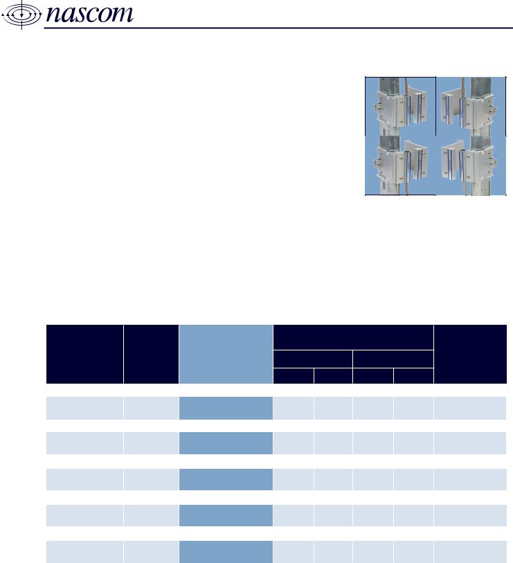
Nascom’s N505AUTM 2 1/4” TRACK MOUNT FLIP SWITCHTM with universal
magnet handles commercial and industrial overhead door applications.
The TRACK MOUNT FLIP SWITCHTM combines the installers’ choice of
contact conguration with an N35 grade NdFeB magnet for maximum gap
performance.
The closed loop versions of the N505AUTM prevents false alarms caused by
the up and down movement of overhead doors with our unique NO DEAD
SPOT™ technology. The switch can be mounted with the cable in either
direction, without loss of gap.
FEATURES
• NO DEAD SPOT™ TECHNOLOGY • EXTRUDED ANNODIZED (TYPE II) ALUMINUM
• QUICK SWITCH NSTALL - LESS THAN 60 SECONDS • FLIP THE SWITCH - GAP IS NOT IMPACTED BY CABLE DIRECTION
• UNIVERSAL MOUNT • 24” STAINLESS STEEL ARMORED CABLE LEAD PROTECTION
• 36” 22AWG WIRE LEADS • LISTED TO UL634 STANDARD
ORDERING INFORMATION
CONTACT RATING
PART
NUMBER
COLOR
OPERATE GAP
(in INCHES)
(Max DC/Peak AC Resistive)
SWITCHING CARRY
V I V I
CLOSED LOOP, NORMALLY OPEN, 1FA, SWITCH/MAGNET SET:
N505AUTM/ST SILVER 1.75 to 2.75 200 VDC 0.5 Amps 10vA 1.5 Amps 150 mOhms
DUAL CLOSED LOOP, NORMALLY OPEN, 1FA, SWITCH/MAGNET SET:
N505AUTM/ST2CR SILVER 1.75 to 2.75 200 VDC 0.5 Amps 10vA 0.5 Amps 150 mOhms
OPEN LOOP, NORMALLY CLOSED, 1FB, SWITCH/MAGNET SET:
N505AUTM/STFB SILVER 1.50 to 2.50 30 VDC 0.2 Amps 3vA 0.5 Amps 100 mOhms
SINGLE POLE DOUBLE THROW, SWITCH/MAGNET SET:
N505AUTM/STSD SILVER 1.50 to 2.50 30 VDC 0.2 Amps 3vA 0.5 Amps 100 mOhms
DOUBLE POLE DOUBLE THROW, SWITCH/MAGNET SET:
N505AUTM/STDD SILVER
1.50 to 2.50 30 VDC 0.2 Amps 3vA 0.5 Amps 100 mOhms
STATIC
CONTACT
RESISTANCE
(50mV, 100mA)
Royne Industries LLC dba NASCOM
|
P: 800.843.5530
|
F: 800.727.4041
|
www.nascominc.com
DWG No. 120405-04 Rev. 2
1

2.883
73.23
3.120
79.25
3.000
76.20
2.880
73.15
3.000
76.20
3.313
84.15
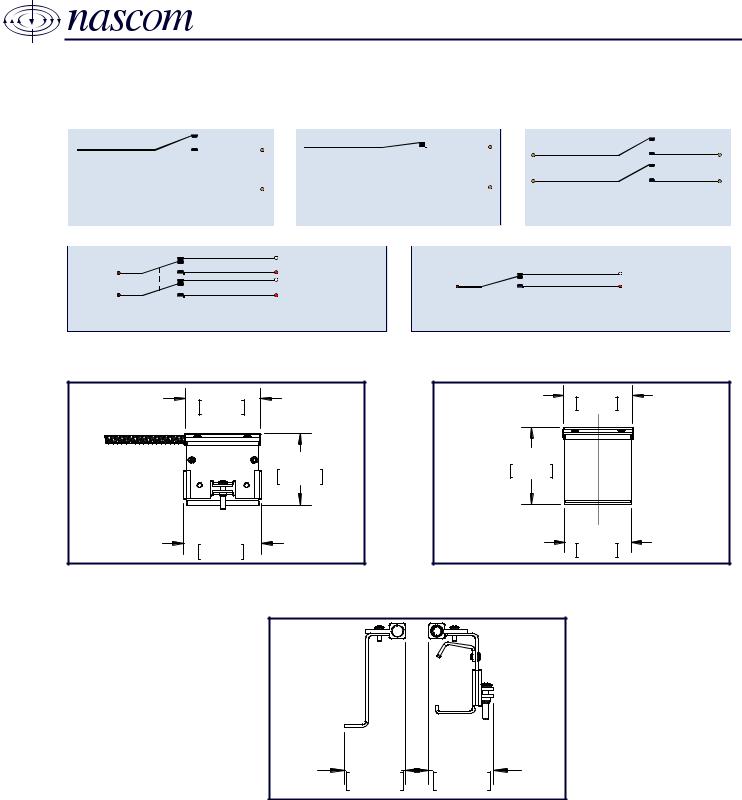
WIRING SCHEMATIC - IN [mm]
N505AUTM
2 1/4” TRACK MOUNT FLIP SWITCH WITH UNIVERSAL MAGNET
SWITCH
CONTACT
CLOSED LOOP,
NORMALLY OPEN CONTACT
COMMON
(BROWN)
COMMON
(BROWN)
DPDT, DOUBLE POLE DOUBLE THROW SPDT, SINGLE POLE DOUBLE THROW
OPEN LOOP,
NORMALLY CLOSED CONTACT
NC, OPEN LOOP (WHITE)
NO, CLOSED LOOP (RED)
NC, OPEN LOOP (WHITE)
SWITCH
CONTACT
COMMON
(BROWN)
DUAL CLOSED LOOP,
NORMALLY OPEN CONTACTS
DIMENSIONS - IN [mm]
NC, OPEN LOOP (WHITE)
NO, CLOSED LOOP (RED)
SWITCH
Royne Industries LLC dba NASCOM
|
P: 800.843.5530
SWITCH/MAGNET SET
|
F: 800.727.4041
MAGNET
|
www.nascominc.com
DWG No. 1200405-04 Rev. 2
2

N505AUTM
2 1/4” TRACK MOUNT FLIP SWITCH WITH UNIVERSAL MAGNET
INSTALLATION INSTRUCTIONS
The N505AU Universal Track Mount switch and magnet system can be installed on either the right or left side of the overhead door. To
change the direction of the direction of the armored cable, remove the 2 screws attaching the switch to the bracket and ip the switch. Insert
and re-tighten the screws.
Depending on the type of Roller Guide Track your door has, or operating condition of the door, it may be necessary to remove the rear half of
the switch bracket to complete installation.
• Un-pack the switch and magnet assemblies and set aside the magnet bracket assembly.
• Slide the two halves of the switch bracket assembly apart so they are fully extended against the clamping screw.
• Position the switch bracket assembly on the guide roller track in the desired location. Make sure the rear half of the bracket assembly
is fully extended around the track.
• Slide the bracket halves together on the track and hold the switch assembly in position. Carefully open and close the door to make
sure the door will operate freely without contacting the switch or bracket assembly. ( If there is interference between the lower guide
roller bracket plate and the switch bracket assembly, use the alternate mounting method below.)
• Secure the switch and bracket assembly to the track by tightening the clamping screw on the side of the bracket.
• With the door closed, align the magnet bracket assembly with the switch. Make sure there is sufcient clearance between the magnet
and switch so the door can open and close freely.
• Attach the magnet to the door using #6 self-tapping screws.
• Connect an ohm meter to the switch leads and open and close the door to test switch for correct operation.
• Connect the switch leads to the alarm system.
Alternate Mounting Method: Use the alternate mounting method if your Roller guide track has a web that will not allow the the rear half of the
switch bracket to wrap around the back of the roller guid track. Or if there is interference between the switch and bracket assembly and the
lower guide roller bracket plate.
• Remove the rear half of the mounting bracket by removing the clamping screw completely and separating the two halves of the bracket
set.
• Position the front half of the bracket with the switch on the rail in the desired location. Using the mounting holes in the side of the
bracket as your guide, drill through the rail using a 3/16 drill in two locations.
• To mount the bracket, use two pan head machine screws. (Note: The screw heads must be on the inside of the rail to allow the door
guide roller to pass). From the inside of the rail, insert the screws through the holes in the rail and through the mounting holes in the
side of the bracket. Place a washer over the screw and use a nylock type lock nut to secure the bracket to the rail. If nylock type nuts
are not available use thread locking compound on the mounting screw threads. This will prevent the mounting screws from loosening
due to vibration from the door opening and closing.
• Open and close the door to make sure the door will operate freely without contacting the switch or mounting bracket.
• With the door closed, re-align the magnet actuator with the switch. Make sure there is sufcient clearance between the magnet and
switch so the door can open and close freely.
• Connect an ohm meter to the switch leads and open and close the door to test the switch for correct operation.
• Connect the switch leads to the alarm system.
Royne Industries LLC dba NASCOM
|
P: 800.843.5530
|
F: 800.727.4041
|
www.nascominc.com
DWG No. 1200405-04 Rev. 2
3

N505AUTM
2 1/4” TRACK MOUNT FLIP SWITCH WITH UNIVERSAL MAGNET
PRODUCT TYPE (1 or 2 digits):
• ST = SWITCH/MAGNET SET
• SW = SWITCH ONLY
• M = MAGNET ONLY
CIRCUIT (0, 2 or 3 digits):
• Blank = CLOSED LOOP
• 2CR = DUAL CLOSED LOOP
• FB = OPEN LOOP
• SD = SPDT
• DD = DPDT
LEAD LENGTH (zero, 3 or 4 digits):
• Blank - 24 Inches
• All other lengths specied in
Inches with 3 digits (e.g. 036 =
36 Inches)
* lead length is armored cable length-
wire length is 12 inches greater
than armored cable length
N505AUTM
WIRE TYPE (0 or 1 digit):
• Blank = UL1061 | 22AWG | 7/30
• J = 2-conductor PVC Jacketed NEC Type
XX XXX/ XXXX X XX XXXX XXXX
CL2 and CM
END OF LINE RESISTOR (zero to 4 digits):
• Blank = Resistor in series with the switch
• P = Resistor in parallel with the switch
• SP = Resistor 1 in series to the switch; resistor
2 in parallel to the switch
BUILT-IN END OF LINE RESISTOR VALUE (zero to 4
digits):
• Blank = No built-in end of line resistor
• All other resistor values are specied (e.g. 1K
= 1,000 Ω)
LEAD WIRE COLOR (zero to 2 digits):
• Blank = Switch Color except:
» resistor contacts standard is red wire
» all 2 conductor jacketed wire is grey
• BL = Blue leads
• OL = Orange leads
Royne Industries LLC dba NASCOM
|
P: 800.843.5530
|
F: 800.727.4041
|
www.nascominc.com
DWG No. 1200405-04 Rev. 2
4