

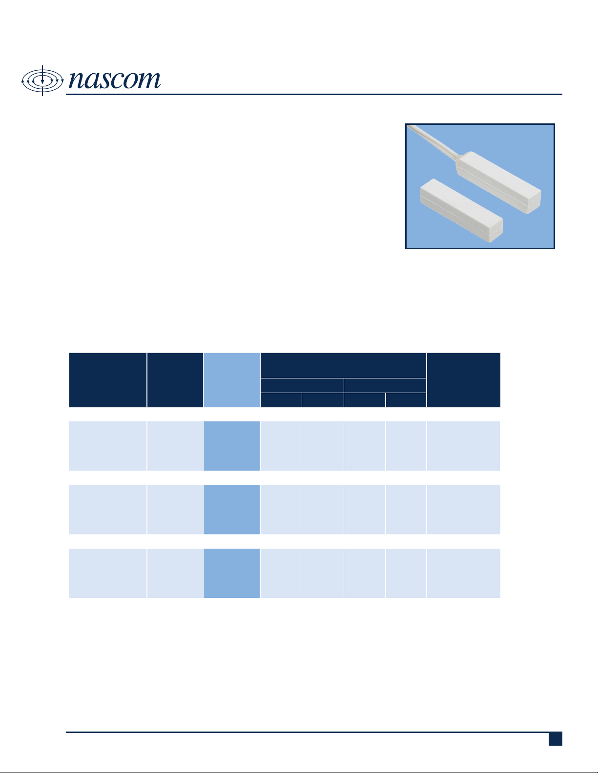
N25WG
STICK ON CONTACT, MINI D1/4” X H1/4” X L1-1/4”, END LEADS
DESCRIPTION
Nascom’s N25WG Series, 1/4” stick on contact, protects all nonferrous (e.g.
wood, aluminum and vinyl) doors and windows, in both residential and commercial settings.
The N25WG is the installer’s choice of contact conguration where excellent
air and side-to-side gap are required to prevent false alarms caused by shifting or warping doors and windows.
FEATURES
• 12” 22AWG WIRE LEADS • ENCAPSULATED HERMETICALLY SEALED CONTACTS
• WIDE GAP - N35 NdFeB RARE EARTH MAGNET • 3M VHB (Very High Bond) DOUBLE SIDED TAPE
• LISTED TO UL634 STANDARD • ABS HOUSINGS
ORDERING INFORMATION
CONTACT RATING
PART
NUMBER
COLOR
OPERATE
GAP
(in inches)
(Max DC/Peak AC Resistive)
SWITCHING CARRY
V I V I
CLOSED LOOP, NORMALLY OPEN, 1FA, SWITCH/MAGNET SET:
N25WGSW/ST
N25WGB/ST
N25WGG/ST
N25WGT/ST
N25WGW/ST
SNOW WHITE
BROWN
GREY
TAN
WHITE
0.75 to 1.125 200 VDC 0.5 Amps 10vA 1.5 Amps 150 mOhms
OPEN LOOP, NORMALLY CLOSED, 1FB, SWITCH/MAGNET SET:
N25WGSW/STFB
N25WGB/STFB
N25WGG/STFB
N25WGT/STFB
N25WGW/STFB
SNOW WHITE
BROWN
GREY
TAN
WHITE
0.65 to 1.00
30 VDC 0.2 Amps 3vA 0.5 Amps 100 mOhms
SINGLE POLE DOUBLE THROW, SWITCH/MAGNET SET:
N25WGSW/STSD
N25WGB/STSD
N25WGG/STSD
N25WGT/STSD
N25WGW/STSD
SNOW WHITE
BROWN
GREY
TAN
WHITE
0.65 to 1.00
30 VDC 0.2 Amps 3vA 0.5 Amps 100 mOhms
STATIC
CONTACT
RESISTANCE
(50mV, 100mA)
Royne Industries LLC, dba NASCOM
|
P: 800.843.5530
|
F: 800.727.4041
|
www.nascominc.com
DWG No. 131118-03 Rev. 1
1
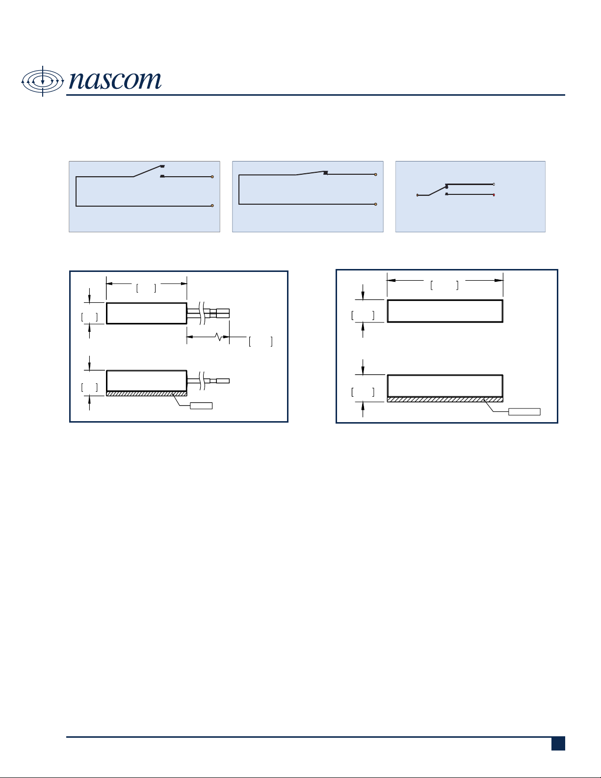
.300
7.62
3M TAPE
1.250
31.75
.250
6.35
11.250
285.75
FRONT VIEW
TOP
VIEW
.300
7.62
3M TAPE
FRONT VIEW
1.250
31.75
.250
6.35
TOP
VIEW
WIRING SCHEMATIC
N25WG
STICK ON CONTACT, MINI D1/4” X H1/4” X L1-1/4”, END LEADS
SWITCH
CONTACT
CLOSED LOOP,
NORMALLY OPEN CONTACT
DIMENSIONS - IN [mm]
SWITCH
SWITCH
CONTACT
OPEN LOOP,
NORMALLY CLOSED CONTACT
NC, OPEN LOOP (WHITE)
COMMON
(BROWN)
SPDT, SINGLE POLE DOUBLE THROW
MAGNET
NO, CLOSED LOOP (RED)
INSTALLATION INSTRUCTIONS
• Pre-t the switch and magnet in the desired location on the window.
• Clean the mounting surface area for both switch and magnet with alcohol and let dry.
• Remove the liner from the tape on the back of the switch and carefully position the switch on the window frame as close
as possible to the movable part of the window.
• Remove the liner from the tape on the back of the magnet and carefully align the magnet parallel with the switch on the
movable part of the window and as close to the window frame as possible.
• Apply rm pressure to the switch and magnet housing to ensure proper adhesion to the mounting surface.
• Connect the switch leads to the alarm system circuit. Caution! Hold wire leads, not the switch housing while cutting and
stripping to prevent damage to switch.
• Test alarm system for correct operation.
Royne Industries LLC, dba NASCOM
DWG No. 131118-03 Rev. 1
|
P: 800.843.5530
|
F: 800.727.4041
|
www.nascominc.com
2

PART NUMBERING SYSTEM
N25WG
STICK ON CONTACT, MINI D1/4” X H1/4” X L1-1/4”, END LEADS
COLOR (1 or 2 digits):
• SW = SNOW WHITE
• B = BROWN
• G = GREY
• T = TAN
• W = WHITE
PRODUCT TYPE (1 or 2 digits):
• ST = SWITCH/MAGNET SET
• SW = SWITCH ONLY
• M = MAGNET ONLY
CIRCUIT (0 or 2 digits):
• Blank = CLOSED LOOP
• FB = OPEN LOOP
• SD = SPDT
LEAD LENGTH (zero, 3 or 4 digits):
• Blank - 12 Inches
• All other lengths specied in
Inches with 3 digits (e.g. 036 =
36 Inches)
N25WG
XX XX XX/ XXXX XX XXX X XX
END OF LINE RESISTOR (zero to 4 digits):
• Blank = Resistor in series with the switch
• P = Resistor in parallel with the switch
• SP = Resistor 1 in series to the switch; resistor
2 in parallel to the switch
BUILT-IN END OF LINE RESISTOR VALUE (zero to 4
digits):
• Blank = No built-in end of line resistor
• All other resistor values are specied (e.g. 1K
= 1,000 Ω)
* END OF LINE RESISTORS NOT AVAILABE FOR SD CIRCUIT
LEAD WIRE COLOR (zero to 2 digits):
• Blank = Switch Color except:
» resistor contacts standard is red wire
» all 2 conductor jacketed wire is grey
• BL = Blue leads
• OL = Orange leads
WIRE TYPE (0 or 1 digit):
• Blank = UL1061 | 22AWG | 7/30
• Z = Zipcord ZIP NEC (UL) TYPE CL2
• J = 2-conductor PVC Jacketed NEC Type CL2
and CM
Royne Industries LLC, dba NASCOM
|
P: 800.843.5530
|
F: 800.727.4041
|
www.nascominc.com
DWG No. 131118-03 Rev. 1
3
 Loading...