

Page 1
Technical Bulletin
T743
Date:
Note:
Previous T.B.’s required: Revised from T743-H2005-05
❑❑❑❑
❑❑❑❑
DESCRIPTION: You may have the complaint that the subwoofer or other channels are
popping when switching inputs or when turning on and off.
REASON: The channel that is popping may have a muting transistor damaged due to an
external source or subwoofer causing static damage to the transistor.
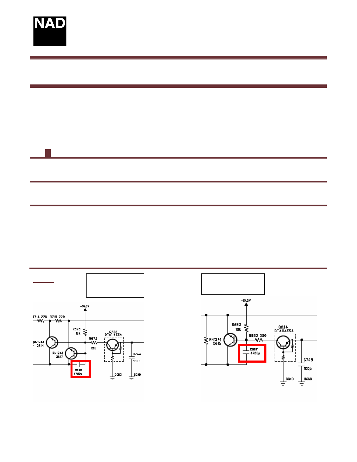
SOLUTION: Replace the transistor and install a 4700 pF capacitor between the base and
collector on the pre amp pc board , as shown in the following two schematics. The use of a
surface mount capacitor is recommended. Placing the capacitor on the bottom of the board
between the base and collector of each muting transistor is preferred . See figure 2 on page 2.
Note: It is recommended to install this capacitor to each channel’s muting transistor.The
following are the designations of the muting transistors, Q608,Q609,Q610,Q611,Q615,Q617.
Figure 1
Product: A/V Receiver
Hardware Technical Bulletin: T743-H2005-05R
March 7/05 Subject: Static protection for
muting transistors
Implemented in production from serial number:R49T74310201
YES
NO
muting circuit
Subwoofer/Multi.
muting circuit
All other channels
Page 1 of 2
Page 2
Technical Bulletin
T743
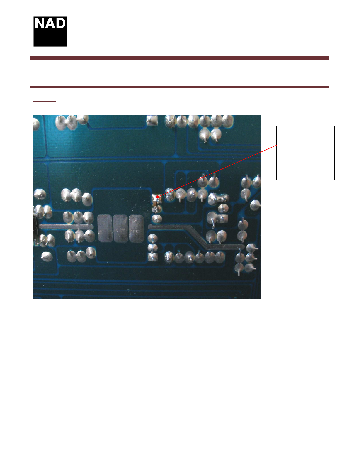
Figure 2
Product: A/V Receiver
Hardware Technical Bulletin: T743-H2005-05R
4700pF surface
mount capacitor
between base and
collector pins of
muting transistor
on the pre amp pc
board
Contact:
NAD Electronics International
633 Granite Court
Pickering, ON Canada L1K 3K1
Voice: 905-831-0799 FAX 905-837-6357
www.nadelectronics.com
Page 2 of 2
Page 3
Technical Bulletin T743
Product: A/V Receiver
Hardware Technical Bulletin: T743-H2004-03
Date:
Note:
Previous T.B.’s required:
DESCRIPTION: To improve the compatibility of HDTV signals with some TV/Monitors.
REASON: When decoding HDTV signals some TV/Monitors may experience horizontal
sync loss.
SOLUTION: Perform the following change to the Component video board.
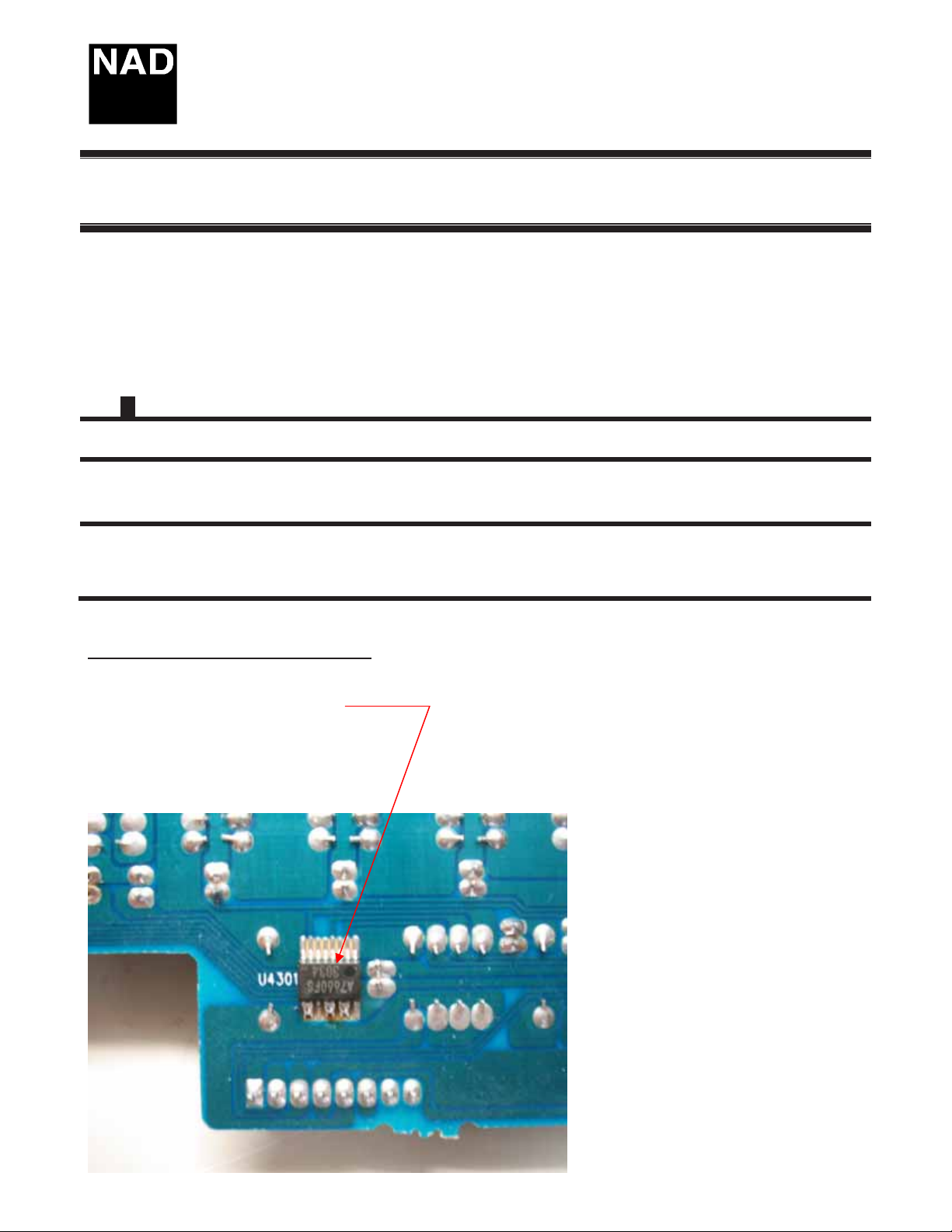
On the component video PCB U4301
June 1, 2004 Subject: HDTV Component
Video change
Implemented in production from Serial number: R44 series and onwards
T
T
YES
NO
A) Link the following pins on U4301;
Pins 9 to 10
Pins 12 to 13
Pins 14 to 15
Figure1
Page 1 OF 2
Page 4
Technical Bulletin T743
Product: A/V Receiver
Hardware Technical Bulletin: T743-H2004-03
HDTV Component Video Change
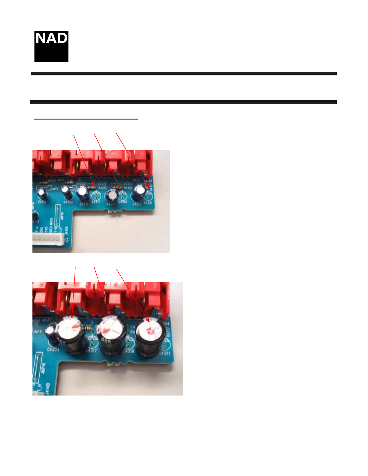
B) Remove C4317, C4319, C4321.
Figure 2
C) Replace C4316, C4318, and C4320 with 1000 uF 6V.
Figure 3
Contact:
NAD Electronics International
633 Granite Court
Pickering, ON Canada L1K 3K1
Voice: 905-831-0799 FAX 905-837-6357
www.nadelectronics.com
Page 2 OF 2
Page 5

Technical Bulletin
T743
Date:
Note:
Previous T.B.’s required:
❑❑❑❑
❑❑❑❑
DESCRIPTION: Unit may shut down, shortly after turn on.
REASON: There is a diode on the standby board that maybe operating intermittantly.
SOLUTION: Locate and identify D756 on the standby board. Change only if the diode is a
1N4148. Change from a 1N4148 to a 1N4004 or equivalent. See figure 1 for details.
Figure 1
Product: A/V Receiver
Hardware Technical Bulletin: T743-H2005-06
February 28/05
Implemented in production from serial number:R44T74306601
YES
NO
Subject:
Intermittantly shuts down
D756
CHANGE
FROM
1N4148 TO
1N4004
Contact:
NAD Electronics International
633 Granite Court
Pickering, ON Canada L1K 3K1
Voice: 905-831-0799 FAX 905-837-6357
www.nadelectronics.com
Page 1 of 1
Page 6

Technical Bulletin T743
Product: A/V Receiver
Hardware Technical Bulletin: T743-H2004-01
Date:
Note:
Previous T.B.’s required:
T
T
DESCRIPTION: : At high volume with no signal on an un-terminated input analogue input,
there maybe some residual noise from one or more channels
REASON: The residual noise is coming from the DSP PC board and power supply ground.
SOLUTION: Perform the following ground changes to lower residual noise.
1. Cut the wire running to J701 located between JMP119 and JMP161 on the main pc
board, located directly opposite U704 (a regulator tied to heatsink).
May 20.2004 Subject: Residual Noise
Implemented in production from Serial number:
1. From R44T74304001~4500
2. From R44T74305861~6400
3. From R44T74306601~Onwards
YES
NO
2. Cut the ground of the shielded cable J715 between Main board and DSP board, cut
this at the DSP side plug. See figure 1.
Figure 1
Cut this black GND wire
at the DSP side as
shown
Page 1 of 5
Page 7

Technical Bulletin T743
Product: A/V Receiver
Hardware Technical Bulletin: T743-H2004-01
3. Add a jumper from the Multi channel RCA connector to the Pre Amp RCA connector.
See figure 2.
Figure 2
Multi-channel RCA connector
to Pre Amp RCA connector
GND wire.
Contact:
NAD Electronics International
633 Granite Court
Pickering, ON Canada L1K 3K1
Voice: 905-831-0799 FAX 905-837-6357
www.nadelectronics.com
Page 2 of 5
Page 8

Technical Bulletin T743
Product: A/V Receiver
Hardware Technical Bulletin: T743-H2004-01
4. Add jumper wire from the DSP board analog ground to the Pre Amp RCA jack. See
figure 3.
5. Add jumper between Preout RCA jack and Surround Power Amp input ground See
figure 3 and figure 4.
Figure 3
Wire from Pre
Amp RCA to
Surround Amp
Contact:
NAD Electronics International
633 Granite Court
Pickering, ON Canada L1K 3K1
Voice: 905-831-0799 FAX 905-837-6357
www.nadelectronics.com
GND wire from
DSP board to Pre
Amp board
Page 3 of 5
Page 9

Technical Bulletin T743
Product: A/V Receiver
Hardware Technical Bulletin: T743-H2004-01
Figure 4
Wire from RCA connector
GND to Surround Amp GND.
6. Mount the keyboard cable jumper wire to the chassis using the nearest front panel
mounting screw. This originally is tied to the DSP analog ground. See figure 5. Float
the analog ground of the DSP board from chassis.
Figure 5
Page 4 of 5
Page 10

Technical Bulletin T743
Product: A/V Receiver
Hardware Technical Bulletin: T743-H2004-01
7. There are 2 screws on the DSP board, the one located nearest to volume knob is the
one that has to be isolated. Remove that screw and put an insulator between the PCB
copper side and front panel chassis. See figures 5, 6.
Figure 6
Contact:
NAD Electronics International
633 Granite Court
Pickering, ON Canada L1K 3K1
Voice: 905-831-0799 FAX 905-837-6357
www.nadelectronics.com
Page 5 of 5
Page 11

Technical Bulletin
T743
Product: A/V Receivers
Hardware Technical Bulletin: T743-H2004-02
Date: June 15
Note:
Previous T.B.’s required:
T
T
DESCRIPTION: The unit may be experiencing intermittent audio or display. The unit may
not always power up.
REASON: The flat ribbon cables, primarily the ones running from the front panel but may
include all flat ribbon cables. They may have intermittent contact due to oxidization.
SOLUTION: Clean all ribbon connectors using an eraser or preferably a non alcohol based
cleaner which will leave no residue. See figures 1, 2 and 3.
NO
, 2004 Subject: Flat Ribbon Cables
YES
Figure 1
Locate and remove the
ribbon cables, front
panel cables shown.
Page 1 of 2
Page 12

Technical Bulletin
T743
Product: A/V Receivers
Hardware Technical Bulletin: T743-H2004-02
Ribbon cables are easily
unplugged from these
Figure 2
Figure 3
Contact:
NAD Electronics International
633 Granite Court
Pickering, ON Canada L1K 3K1
Voice: 905-831-0799 FAX 905-837-6357
www.nadelectronics.com
Clean the ends of the
ribbon cables with
eraser or non alcohol
based cleaners.
Page 2 of 2
 Loading...