

NAD S-250 Service manual

SERVICE MANUAL
S250
FIVE CHANNEL
S250
FIVE CHANNEL
POWER AMPLIFIER
POWER AMPLIFIER

CONTENTS
FRONT PANEL / REAR PANEL VIEW . . . . . . . . . . . . . . . . . . . . . . . . . . . . . . . . . . . 3
SPECIFICATIONS . . . . . . . . . . . . . . . . . . . . . . . . . . . . . . . . . . . . . . . . . . . . . . . . . . . 4
ALIGNMENT PROCEDURE / ALIGNMENT POINTS . . . . . . . . . . . . . . . . . . . . . . . . 5
WIRING DIAGRAM . . . . . . . . . . . . . . . . . . . . . . . . . . . . . . . . . . . . . . . . . . . . . . . . . . 6
PCB LAYOUT . . . . . . . . . . . . . . . . . . . . . . . . . . . . . . . . . . . . . . . . . . . . . . . . . . . . . 7-8
SCHEMATIC DIAGRAM . . . . . . . . . . . . . . . . . . . . . . . . . . . . . . . . . . . . . . . . . . . . 9-11
ELECTRICAL PARTS LIST . . . . . . . . . . . . . . . . . . . . . . . . . . . . . . . . . . . . . . . . . 12-14
EXPLODED VIEW . . . . . . . . . . . . . . . . . . . . . . . . . . . . . . . . . . . . . . . . . . . . . . . . . . 15
EXPLODED VIEW PARTS LIST . . . . . . . . . . . . . . . . . . . . . . . . . . . . . . . . . . . . . . . 16
PACKING DIAGRAM . . . . . . . . . . . . . . . . . . . . . . . . . . . . . . . . . . . . . . . . . . . . . . . . 17
SERVICE SAFETY PRECAUTIONS
1. Replacing the Fuses
CAUTION: FOR CONTINUED PROTECTION AGAINST THE RISK OF FIRE REPLACE ONLY
WITH SAME TYPE OF FUSE.
REFERENCE NO. PART NUMBER DESCRIPTION
PSU Board
F1*AH 5120-0506-0 12.5A 250V Time Lag 6.3x32mm UR
F1*C 5120-0025-0 6.3A 250V HBC Time Lag 5x20mm SEMKO/VDE
!
!
Amp Board
F1-F2*AH 5120-0040-0 6.3A 250V Time Lag 5x20mm UL
F1-F2*C 5120-0025-0 6.3A 250V HBC Time Lag 5x20mm SEMKO/VDE
NOTE:
*AH : North American version only
*C : European version only
!
!
2. Safety-check out (North American model only)
Before returning the product to the customer, make leakage current or resistance measurements
to determine that exposed parts are acceptably insulated from the supply circuit.
Parts marked with the symbol are critical with regard to the risk of fire and electric shock.
Replace only with parts recommended by the manufacturer.
!
FRONT PANEL / REAR PANEL VIEW
RETURN TO CONTENTS
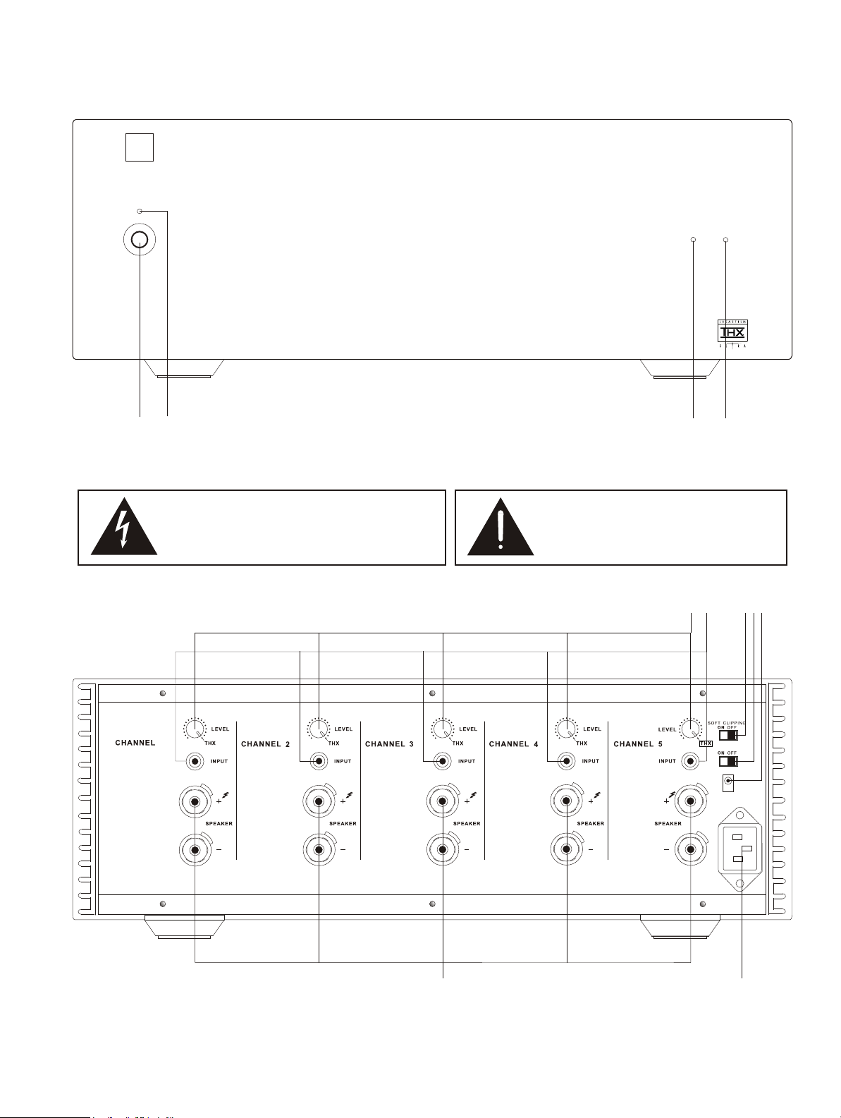
FRONT PANEL CONTROLS
NA
1 2
D
Five Channel Power Amplifier S250
1. POWER SWITCH 3. PROTECTION INDICATOR
2. POWER INDICATOR 4. SOFT CLIPPING INDICATOR
The graphic symbol of a lightning flash with an arrow point
within a triangle signifies that there is dangerous voltage
within the unit and it posses a hazard to anyone removing
the cover to gain access to the interior of the unit. Only
qualified service personnel should make such attempt.
The graphic symbol of an exclamation point within
an equilateral triangle warns a user of the device
that it is necessary to refer to the instruction
manual and its warnings for proper operation of
the unit.
PROTECTION
3
SOFT CLIPPING
4
REAR PANEL CONNECTIONS
1
1. LEVEL CONTROL 5. 12V TRIGGER INPUT
2. INPUT JACK 6. SPEAKER TERMINALS
3. SOFT CLIPPING SWITCH 7. AC INLET
4. AUTO TRIGGER SWITCH
2
3
AUTO TRIGGER
TRIGGER IN
AC MAINS INPUT
120V
4 5
7
1
+12V
6

SPECIFICATIONS
RETURN TO CONTENTS
Specifications are measured in accordance with IHF standard IHF-A-202, 1978.
NOMINAL LIMIT
1. THD #0.02% #0.03%
2. Continuous Power Output 8 ohms $125W $100W
20kHz, 5 ch. for 8 ohms, 4 ch. for 4 ohms) 4 ohms $125W $100W
3. Clipping Power $135W $110W
4. S/N Ratio A-wtd $96dB $93dB
maximum) Audio BPF $89dB $86dB
5. Frequency Response 0 ~ -0.1dB 0 ~ -0.25dB
6. Input Sensitivity 100 ± 2 mV 100 ± 3 mV
maximum)
7. Channel Separation 1kHz $77dB $70dB
20kHz $67dB $50dB
8. Soft Clipping
Output Reduction 0.4 ~ 0.6 dB 0.3 ~ 1.0 dB
THD 5 ~ 6.5% 4 ~ 10%
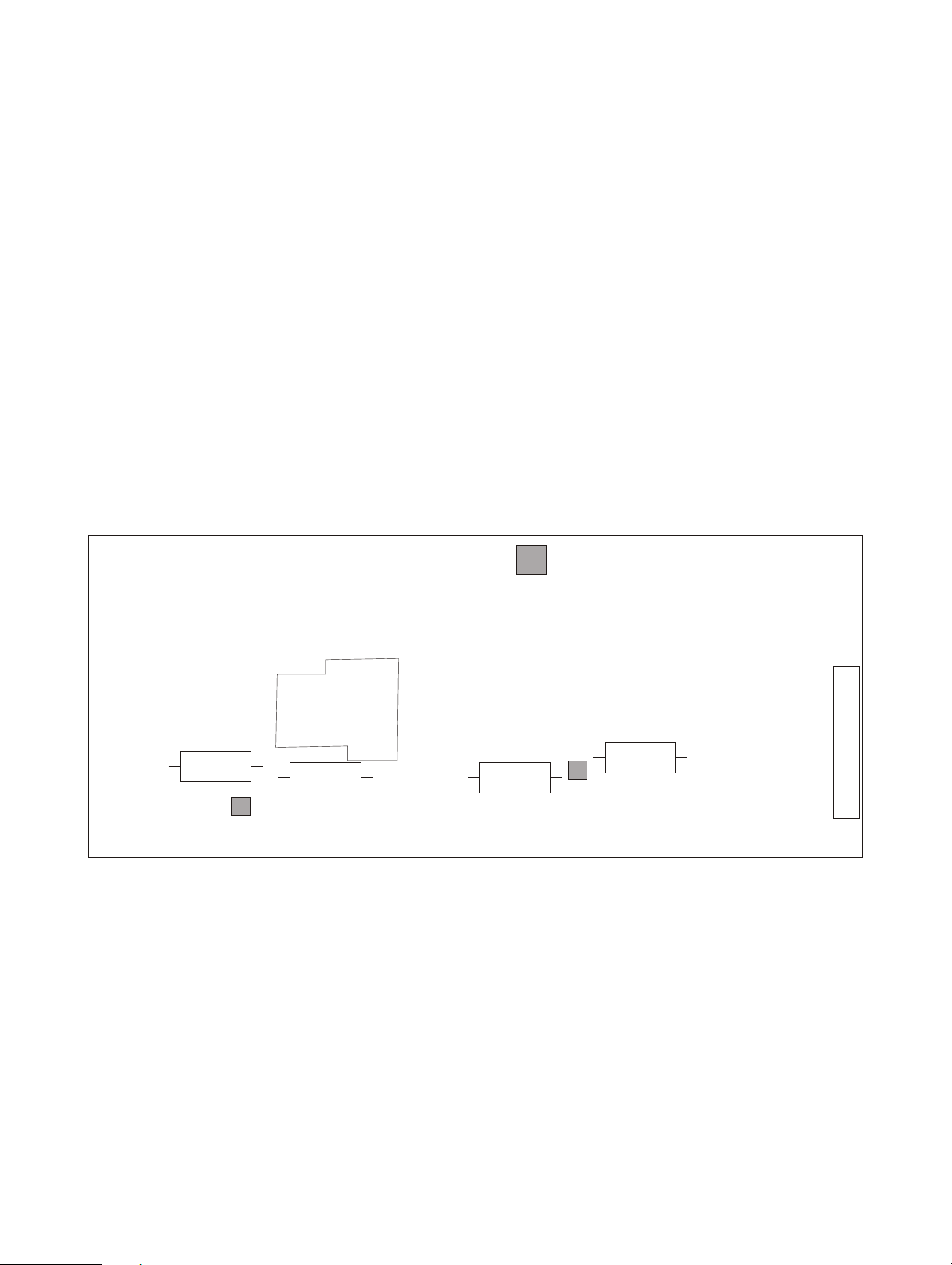
ALIGNMENT PROCEDURE
RETURN TO CONTENTS
IDLE CURRENT ALIGNMENT FOR EVERY POWER AMPLIFIER MODULE
1. Remove the load and the input signal.
2. Connect a digital voltmeter between TP1 and TP2.
3. Switch the amplifier on and, after one minute, adjust R27 to obtain a reading of
5mV ±0.5mV.
4. Leave power on for 3 minutes to allow the idle currents to stabilize. Re-adjust R27
as necessary to obtain a reading of 4.4mV ±0.5mV.
ADJUSTMENT POINTS
R44
TP1
RELAY
R40
R27
J1
R45
R41
TP2
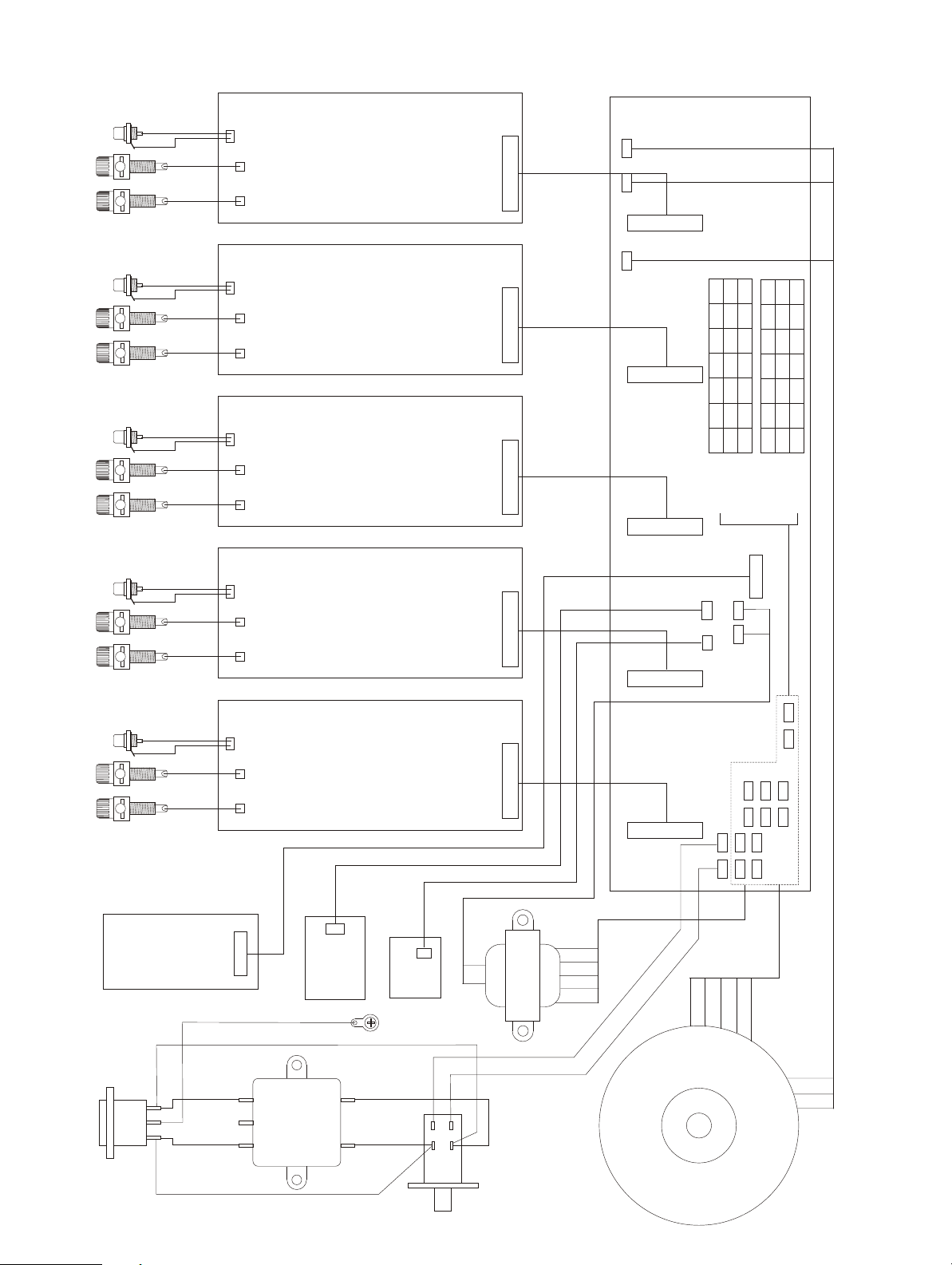
WIRING DIAGRAM
RETURN TO CONTENTS
+
RED
BLK
RED
BLK
RED
WHT
J2
J3 +
J4 -
CHANNEL 1
AMP BOARD
J19
J1
1
J17
1
VIO
ORN
RED
BLK
RED
BLK
RED
BLK
RED
BLK
RED
BLK
RED
WHT
RED
BLK
RED
WHT
RED
BLK
RED
WHT
RED
BLK
RED
WHT
J1
+
J2
J3 +
CHANNEL 2
AMP BOARD
J4 -
+
J2
J3 +
CHANNEL 3
AMP BOARD
J4 -
+
J2
J3 +
CHANNEL 4
AMP BOARD
J4 -
+
J2
J3 +
CHANNEL 5
AMP BOARD
J4 -
J1
1
J1
1
J1
1
J1
1
J18
M6
M5
M4
1
M3
J2
J3
J4
M2
M1
1
J27
1
J28
1
1
PSU BOARD
1
J5
PSL
PSN
—
BLU
RED
RED
BLU
WHT
—
WHT
BLK
BLK
BRN
BRN
120V
230V
MAIN
TRANSFORMER
SS2
YEL
SS1
YEL
M2
S2
S3
S1
M5
GRY
S6
S5
S4
S3
S2
S1
J26
1
M4
S4S5S6
—
BRN
BLU
RED
WHT
BLK
120V
STANDBY
M6
BLU
BRN
RED
—
WHT
BLK
230V
TRANSFORMER
M1
M3
J22
1
GRN-YEL (230V ONLY)
BLU (120V)
BLU (230V)
BRN (230V)
EMI FILTER
BRN (120V)
AC INLET
SWITCH
TRIGGER
N
E
L
BOARD
J24
1
LED BD
PROT/SC
CHASSIS
BLU (230V)
BRN (230V)
J25
PWR
LED
1
BD
YEL
YEL
BRN
BLU
POWER SWITCH
BRN
BLK
WHT
BLU
STANDBY
RED
TRANSFORMER
BRN
MAIN
TRANSFORMER
BLK
WHT
BLU
RED
VIO
ORN
GRY
 Loading...