

Page 1
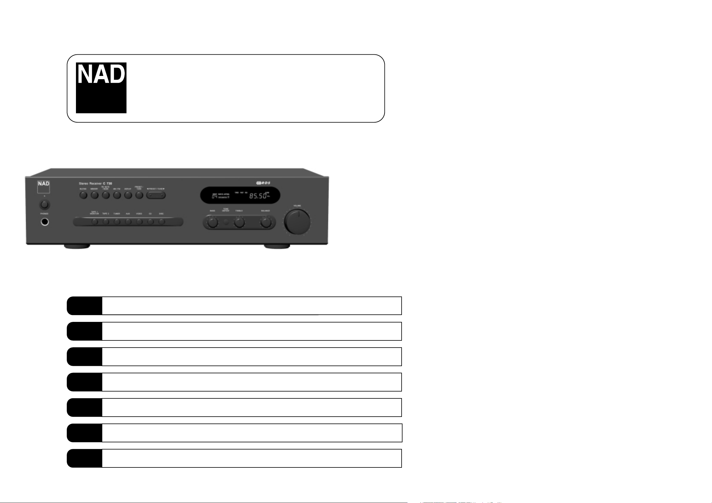
C730
Stereo AM/FM Receiver
Owner’s Manual
GB
Manuel d’Installation
F
Bedienungsanleitung
D
Manual del Usuario
E
Manuale delle Istruzioni
I
Manual do Proprietário
P
Bruksanvisning
S
Page 2
3
Warning: To reduce the risk of fire or electric shock, do not
expose this unit to rain or moisture.
The lightning flash with an arrowhead symbol within an equilateral
triangle, is intended to alert the user to the presence of uninsulated
“dangerous voltage” within the product’s enclosure that may be of
sufficient magnitude to constitute a risk of electric shock to persons.
The exclamation point within an equilateral triangle is intended to
alert the user to the presence of important operating and
maintenance (servicing) instructions in the literature accompanying
the product.
Do not place this unit on an unstable cart, stand or tripod, bracket
or table. The unit may fall, causing serious injury to a child or adult
and serious damage to the unit. Use only with a cart, stand, tripod,
bracket or table recommended by the manufacturer or sold with
the unit. Any mounting of the device on a wall or ceiling should
follow the manufacturer’s instructions and should use a mounting
accessory recommended by the manufacturer.
An appliance and cart combination should be moved with care.
Quick stops, excessive force and uneven surfaces may cause the
appliance and cart combination to overturn.
Read and follow all the safety and operating instructions before
connecting or using this unit. Retain this notice and the owner’s
manual for future reference.
All warnings on the unit and in its operating instructions should be
adhered to.
Do not use this unit near water; for example, near a bath tub,
washbowl, kitchen sink, laundry tub, in a wet basement or near a
swimming pool.
The unit should be installed so that its location or position does not
interfere with its proper ventilation. For example, it should not be
situated on a bed, sofa, rug or similar surface that may block the
ventilation openings; or placed in a built-in installation, such as a
bookcase or cabinet, that may impede the flow of air through its
ventilation openings.
The unit should be situated from heat sources such as radiators,
heat registers, stoves or other devices (including amplifiers) that
produce heat.
The unit should be connected to a power supply outlet only of the
voltage and frequency marked on its rear panel.
The power supply cord should be routed so that it is not likely to be
walked on or pinched, especially near the plug, convenience
receptacles, or where the cord exits from the unit.
Unplug the unit from the wall outlet before cleaning. Never use
benzine, thinner or other solvents for cleaning. Use only a soft
damp cloth.
The power supply cord of the unit should be unplugged from the
wall outlet when it is to be unused for a long period of time.
Care should be taken so that objects do not fall, and liquids are not
spilled into the enclosure through any openings.
This unit should be serviced by qualified service personnel when:
A. The power cord or the plug has been damaged; or
B. Objects have fallen, or liquid has been spilled into the unit; or
C. The unit has been exposed to rain or liquids of any kind; or
D. The unit does not appear to operate normally or exhibits a
marked change in performance; or
E. The device has been dropped or the enclosure damaged.
DO NOT ATTEMPT SERVICING OF THIS UNIT
YOURSELF. REFER SERVICING TO QUALIFIED
SERVICE PERSONNEL
Upon completion of any servicing or repairs, request the service
shop’s assurance that only Factory Authorized Replacement Parts
with the same characteristics as the original parts have been used,
and that the routine safety checks have been performed to
guarantee that the equipment is in safe operating condition.
REPLACEMENT WITH UNAUTHORIZED PARTS MAY RESULT IN FIRE,
ELECTRIC SHOCK OR OTHER HAZARDS.
ATTENTION
POUR ÉVITER LES CHOC ELECTRIQUES, INTRODUIRE LA
LAME LA PLUS LARGE DE LA FICHE DANS LA BORNE
CORRESPONDANTE DE LA PRISE ET POUSSER JUSQU’AU
FOND.
CAUTION
TO PREVENT ELECTRIC SHOCK, MATCH WIDE BLADE OF
PLUG TO WIDE SLOT FULLY INSERT.
If an indoor antenna is used (either built into the set or installed
separately), never allow any part of the antenna to touch the metal
parts of other electrical appliances such as a lamp, TV set etc.
CAUTION
POWER LINES
Any outdoor antenna must be located away from all power lines.
OUTDOOR ANTENNA GROUNDING
If an outside antenna is connected to your tuner or tunerpreamplifier, be sure the antenna system is grounded so as to
provide some protection against voltage surges and built-up static
charges. Article 810 of the National Electrical Code, ANSI/NFPA No.
70-1984, provides information with respect to proper grounding of
the mast and supporting structure, grounding of the lead-in wire to
an antenna discharge unit, size of grounding conductors, location of
antenna discharge unit, connection to grounding electrodes and
requirements for the grounding electrode.
a. Use No. 10 AWG (5.3mm2) copper, No. 8 AWG (8.4mm2)
aluminium, No. 17 AWG (1.0mm2) copper-clad steel or bronze
wire, or larger, as a ground wire.
b. Secure antenna lead-in and ground wires to house with stand-off
insulators spaced from 4-6 feet (1.22 - 1.83 m) apart.
c. Mount antenna discharge unit as close as possible to where lead-
in enters house.
d. Use jumper wire not smaller than No.6 AWG (13.3mm2) copper,
or the equivalent, when a separate antenna-grounding electrode
is used. see NEC Section 810-21 (j).
EXAMPLE OF ANTENNA GROUNDING AS PER NATIONAL ELECTRICAL
CODE INSTRUCTIONS CONTAINED IN ARTICLE 810 - RADIO AND
TELEVISION EQUIPMENT.
NOTE TO CATV SYSTEM INSTALLER: This reminder is
provided to call the CATV system installer’s attention to
Article 820-40 of the National Electrical Code that provides
guidelines for proper grounding and, in particular, specifies
that the ground cable ground shall be connected to the
grounding system of the building, as close to the point of
cable entry as practical.
CAUTION
RISK OF ELECTRIC
SHOCK DO NOT OPEN
A TTENTION:
RISQUE DE CHOC ELECTRIQUE
NE PAS OUVRIR
CAUTION: TO REDUCE THE RISK OF ELECTRIC
SHOCK, DO NOT REMOVE COVER (OR BACK). NO
USER SERVICEABLE PARTS INSIDE. REFER SERVICING
TO QUALIFIED SERVICE PERSONNEL.
IMPORTANT SAFETY INSTRUCTIONS
2
1. REAR PANEL CONNECTIONS
3. FRONT PANEL CONTROLS
2. ANTENNA CONNECTION
4. REMOTE CONTROL HANDSET
Page 3

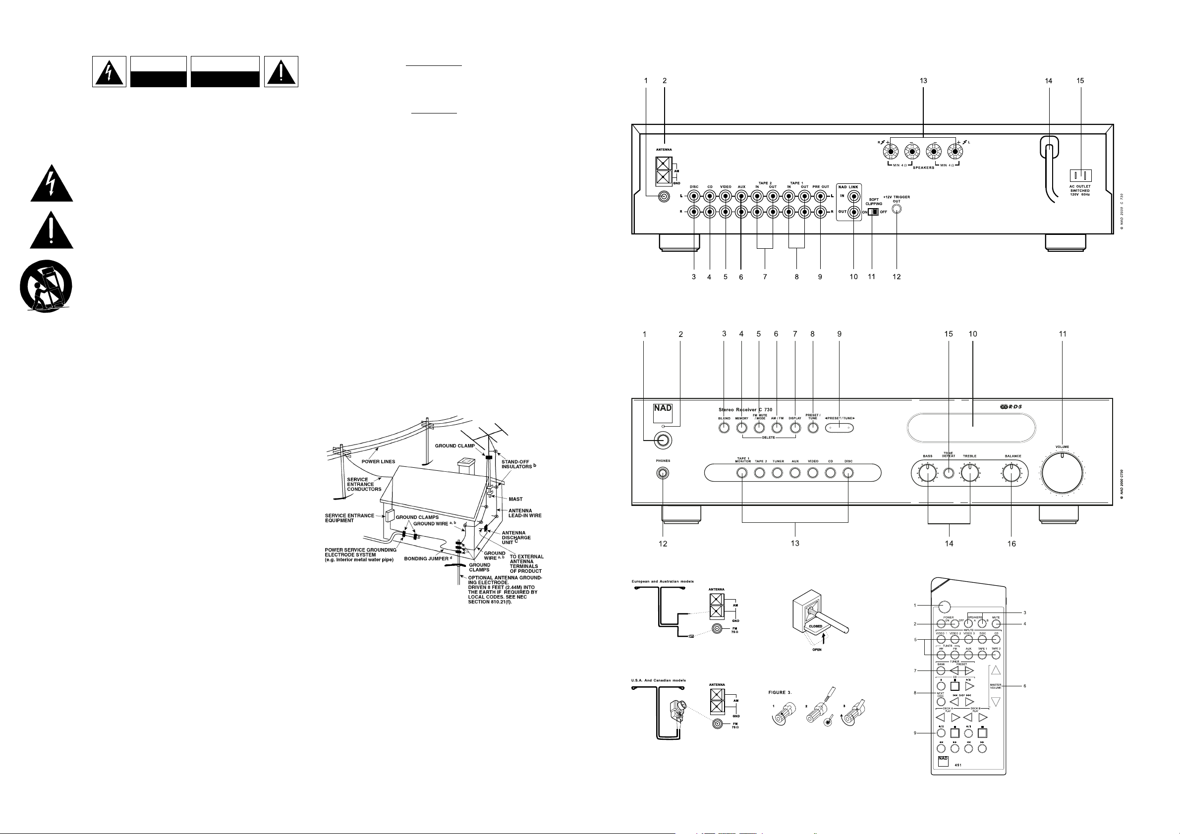
10. NAD-LINK IN, OUT
The NAD-Link connector is used to pass commands from other
units fitted with NAD-Link connectors. This allows centralised
control of a complete system, and also allows some of the basic
functions of other NAD components (such as a CD player or
cassette-deck) also equipped with NAD-Link to be controlled with
the amplifier’s remote control. To function with such other units,
connect the C730’s NAD-Link Out to the NAD-Link In on the other
unit. NAD-Link connectors can be daisy-chained, IN to OUT, so
that a whole system can be controlled from the remote control
facilities of one unit.
NOTES: It is advisable not to connect NAD-Link if these units that
have their own built-in remote control command receiver and are
positioned together, in direct view from the remote control
handset. If you are unsure, try operating the products without
NAD-Link first; If the unit responds to the remote control
command, it will not be necessary to connect NAD-Link.
Never loop the last unit back to the first NAD unit in the NAD-Link
chain. Unplug all units from the mains before connecting or
disconnecting NAD-Link.
11. SOFT CLIPPING™
When an amplifier is driven beyond its specified power output, a
hard, distorted sound can be heard on very loud sounds. This is
caused by the amplifier cutting off or “hard clipping” the peaks of
sound that it was not designed to reproduce. The NAD Soft
Clipping™ circuit gently limits the output of the system to
minimise audible distortion if the amplifier is overdriven.
If your listening involves moderate power levels you may leave the
Soft Clipping™ switch to Off. If you are likely to play at high levels,
that could stretch the amplifier’s power capability, then switch Soft
Clip On.
12. 12V TRIGGER OUT
This output allows to remotely switch on or off ancillary
equipment such as a tuner, power amplifier, etc. which are also
equipped with a 12V trigger input. This can also be an AC outlet
power strip equipped with a 12V trigger input. The 12V trigger
output is activated whenever the unit is in switched to normal
operational mode from Stand-by or Off.
For switching Stand-by/Power On of an external component
through the C730, connect the12V-trigger output of the C730 to
the remote component’s DC input jack. The plug required is a
standard 3.5mm Mini-Jack plug (“mono”): The tip is the live or
+ connection, the shaft of the input jack is the 12V-trigger - or
ground connection.
NOTES: Check the specifications of the Trigger input terminal on the
other components to ensure these are compatible with the C730’s
12V-trigger output. NAD components equipped with 12V input
triggers are fully compatible with the C730’s 12V output trigger.
The C730’s 12V-trigger output voltage is 12V DC. The total
maximum current must not exceed 200mA. Typically, NAD 12V
input triggers draw less than 10mA of current. Before making any
connections to any 12V trigger input or output, make sure all
components are disconnected from the AC mains.
Failure to observe the above may result in damage to the C730 or
any ancillary components attached to it. If in doubt over the
connections, installation and operation of the 12V trigger output
consult your NAD dealer.
13. SPEAKERS
Connect the right speaker to the terminals market “R +” and
“R-” ensuring that the “R+” is connected to the “+” terminal on
your loudspeaker and the “R-” is connected to the loudspeaker’s
“-” terminal. Connect the terminals marked “L+” and “L-” to the
left speaker in the same way.
Always use heavy duty (16 gauge; 1.5mm, or thicker) stranded wire
to connect loudspeakers to your NAD C730. The high-current binding
post terminals can be used as a screw terminal for cables terminating
in spade or pin sockets or for cables with bare wire ends.
BARE WIRES AND PIN CONNECTORS
Bare wires and pin sockets should be inserted into the hole in the
shaft of the terminal. Unscrew the speaker terminal’s plastic
bushing until the hole in the screw shaft is revealed. Insert the pin
or bare cable end into the hole and secure the cable by tightening
down the terminal’s bushing.
Ensure bare wire from the speaker cables does not touch the back
panel or another socket . Ensure that there is only 1/2” (1cm) of
bare cable or pin and no loose strands of speakers wire.
NOTE: Make sure the speaker impedance is 4 ohms or more
when connecting only one pair of speakers; make sure the
speaker impedance for all speakers is over 8 ohms when
connecting two sets of speakers.
14. AC LINE CORD
Plug the AC power cord into a live AC wall socket. Make sure all
connections have been made before connecting to mains.
15. SWITCHED AC OUTLET
The AC power cord of another component may be plugged into
this accessory outlet. Components plugged into this outlet will be
switched On and Off by the POWER button on the front panel or
by the ON and STAND-BY button on the remote control handset.
NOTE: The total power consumption of any components
connected to the AC outlets may not exceed 100 Watts.
FRONT PANEL CONTROLS (FIG 3)
1. POWER ON/OFF
Press the POWER button to switch the receiver On. The Stand-by
indicator (No. 2) over the power button will light up amber and
after a short pause will turn to green to indicate the receiver is
now ready for normal operation.
Pressing the POWER switch again will turn the unit OFF
completely, it will not respond to the remote control.
GB
5
QUICK START
1. Connect the speakers to the Speaker terminals and sources to
the relevant input sockets on the rear.
2. Plug in the AC power cord.
3. Press the POWER button to turn on the NAD C730.
4. Press the required input selector.
5. For radio listening, connect AM and FM antenna.
6. Press the AM/FM button to select AM or FM reception.
7. Press Preset/Tune button so that “PRESET” isn’t lit in display;
the tuner is now in Tune mode.
8. Use Preset/Tune or to select a station.
NOTES ON INSTALLATION
Your NAD C730 should be placed on a firm, level surface. Avoid
placing the unit in direct sunlight or near sources of heat and
damp. Allow adequate ventilation. Do not place the unit on a soft
surface like a carpet. Do not place or it in an enclosed position
such a bookcase or cabinet that may impede the air-flow through
the ventilation slots. Make sure the unit is switched off before
making any connections.
The RCA sockets on your NAD C730 are colour coded for
convenience. Red and white are Right and Left audio respectively,
and yellow for NAD Link. Use high quality leads and sockets for
optimum performance and reliability. Ensure that leads and
sockets are not damaged in any way and all sockets are firmly
pushed home.
For best performance, use quality speaker leads of 16 gauge
(1.5mm) thickness or more. If the unit is not going to be used for
some time, disconnect the plug from the AC socket.
Should water get into your NAD C730, shut off the power to the
unit and remove the plug from the AC socket. Have the unit
inspected by a qualified service technician before attempting to
use it again. Do not remove the cover, there are no user-
serviceable parts inside. Use a dry soft cloth to clean the unit.
If necessary, lightly dampen the cloth with soapy water. Do not use
solutions containing benzol or other volatile agents.
REAR PANEL CONNECTIONS (FIG 1)
1. FM ANTENNA
A ribbon wire FM antenna is included and should be connected to
the FM connector at the rear of the unit using the supplied
“balun” adapter (see fig 2). The ribbon aerial should be mounted
on a vertical surface and placed so that it forms a “T”.
Experiment with placement of the antenna to find the position that
gives the best signal strength and lowest background noise. An
inadequate FM signal normally results in high levels of hiss,
especially in stereo, and interference from external electrical
sources. In areas of poor FM reception, the tuner section’s
performance can be improved by using an externally mounted FM
antenna. A qualified aerial installer will be able to advise and fit a
recommended aerial for your reception conditions.
2. AM ANTENNA
An AM loop antenna is supplied with the NAD C730 and is
required for AM reception. To connect the AM antenna, first press
the keys on the Antenna terminals downwards. Insert the bare
antenna wires into the two terminal holes and push the connector
keys upwards again to secure the connection (see fig 2).
Test various positions for the antenna but always ensure the loop
is placed vertically for best reception. Placing the antenna close to
large metal items such as metal shelves or radiators may interfere
with reception.
3. DISC INPUT
Input for additional line level input signals such as CD, Mini Disc
player or the output signal from a step-up amplifier for a
turntable. Use a twin RCA-to-RCA lead to connect the auxiliary
unit’s left and right “Audio Outputs” to this input.
4. CD INPUT
Input for a CD or other line-level signal source. Use a twin RCAto-RCA lead to connect the CD player’s left and right “Audio
Outputs” to this input. The NAD C730 only accepts analogue
signals from your CD player.
5. VIDEO INPUT
Input for the audio signal from a stereo VCR (or stereo
TV/Satellite/Cable receiver) or other line-level audio source.
Using twin RCA-to-RCA leads, connect to the left and right “Audio
Out” of the unit to these inputs. Note: These are audio inputs only.
6. AUX INPUT
Input for additional line level input signals such as another CD
player. Use a twin RCA-to-RCA lead to connect the auxiliary unit’s
left and right “Audio Outputs” to this input.
7. TAPE 2 IN, OUT
Connections for analogue recording and playback to an audio
tape recorder of any type. Using twin RCA-to-RCA leads, connect
to the left and right “Audio Output” of the tape machine to the
TAPE 2 IN sockets for playback. Connect the left and right “Audio
Input” of the tape machine to the TAPE 2 OUT sockets for
recording.
8. TAPE 1 IN, OUT
Connections for analogue recording and playback to a secondary
audio tape recorder of any type. Using twin RCA-to-RCA leads,
connect to the left and right “Audio Output” of the tape machine
to the TAPE 1 IN sockets for playback and tape monitoring.
Connect the left and right “Audio Input” of the tape machine to the
TAPE 1 OUT sockets for recording.
9. PRE OUT
The NAD C730 allows for the connection of a different or additional
power amplifier. If you are using an external stereo power
amplifier, use a twin RCA-to-RCA lead to connect to the left and
right “Audio Input” of the Power amp to the PRE OUT 1 sockets.
NOTES: Always turn the C730 and associated external power
amplifiers off before connecting or disconnecting anything to the
PRE-OUT sockets.
The PRE-OUT output signal will be affected by the NAD C730’s
volume and tone control settings.
GB
4
NAD C730 Stereo AM/FM Receiver
Page 4

8. PRESET/TUNE
The Preset/Tune button toggles between two different modes:
a) Preset mode: In this mode you can use the Tune/Preset
or buttons (No. 9) to select a Preset. When Preset Mode
is selected “PRESET” will scroll once through the display and
the PRESET indicator lights up in the display.
b) Tune mode: By pressing the Preset/Tune button (No. 9)
or you can engage automatic or manual tuning
respectively down or up the frequency band. When Tune mode
is selected, “TUNE” will scroll through the display once.
9. PRESET/TUNE AND
The function of these buttons depends on the tuning mode
selected with the Preset/Tune button (No. 8). The Preset/Tune
button toggles between the two operation modes:
a) Preset mode (indicated in the display area): Press the
(down) button to scroll to a lower number Preset; press the
(up) button to scroll to a higher Preset number. This is a
“wrap-around” function, so that going from the highest
number Preset, the tuner will go to the lowest Preset number
or vice-versa when tuning either up or down.
b) Tune mode: Press the (down) or (up) button for
more than 1 second to engage automatic tuning respectively up
or down the frequency band. The tuner will search
automatically for the first reasonably strong radio station,
where it will stop. Press the Down/Up button again for 1
second to start searching again.
By briefly tapping the (down) or (up) buttons you can
engage manual tuning respectively up or down the frequency band
for precise tuning to a specific frequency. With each successive tap
of the keys, the tuner will take 0.05 MHz steps on FM so you can
accurately tune into the desired frequency. For AM the tuning steps
are set at 10 kHz (120V version) or 9 kHz (230V version).
This tuning mode can also be useful when trying to receive a radio
station, which is too weak for the auto search mode. When tuned
accurately to a station, “TUNED” will light up in the display. The
muting circuit, however may suppress very weak radio station
signals. If such a very weak station is in stereo it will have a high
level of background hiss. Switching to Mono Mode and
disengaging the muting circuit by depressing the FM MUTE/MODE
button (No. 5) will allow the station to be heard and will cancel
most or all of this background noise.
NOTES: Automatic tuning is available on both FM and AM.
Even if the C730 is in Tune Mode, the remote control’s Preset Up
and Down buttons will only change presets.
The Preset/Tune and buttons are also used in
conjunction with the Memory (No. 4) and Display (No. 7) buttons
to add and memorise user defined names to Presets. Refer to the
separate chapter “Storing, Recalling and Labelling Presets” for
more information.
10. DISPLAY AREA
The display area gives all vital information on the status of the
receiver. Displayed are:
• Which input is selected
• Volume MUTE On
• Tape Monitor engaged
• Tone Defeat On
• Band and frequency of current station, RDS PS (station name),
or RDS Radio Text. The latter two only if RDS is available; select
using the Display button (No. 7).
• If an FM Stereo broadcast is received.
• If the FM station also broadcasts RDS.
• If “Memory” has been engaged
• Preset number if the current station is stored in the tuner’s
memory bank.
• If Blend and FM Mute/Mode are switched On.
• Radio Signal Strength. The bars just below “ANTENNA” indicate
the radio station’s signal strength. The more bars are lit, the
stronger the station.
NOTE: The infrared sensor, which receives commands from a
remote control (not supplied), is located on the left side of the
display window. There must be a clear line-of-sight path from the
remote control to this window; if that path is obstructed, the
remote control may not work.
11. VOLUME
The VOLUME control adjusts the overall loudness of the signals
being fed to the loudspeakers. It is motor driven and can be
adjusted from the remote control handset. The VOLUME control
does not affect recordings made using the Tape outputs but will
affect the signal going to the Pre-amp output (Pre Out).
On the remote control handset, press the MUTE Button to
temporarily switch off the sound to the speakers and headphones.
Mute mode is indicated by “MUTE” flashing in red in the display
area. Press MUTE again to restore sound. Mute does not affect
recordings made using the Tape outputs but will affect the signal
going to the Pre-amp output (Pre Out).
12. HEADPHONE SOCKET
A 1/4” stereo jack socket is supplied for headphone listening and
will work with conventional headphones of any impedance.
Inserting a headphone jack into this socket automatically switches
off the loudspeakers. The volume, tone and balance controls are
operative for headphone listening. Use a suitable adapter to
connect headphones with other types of sockets, such as 3.5mm
stereo “personal stereo” jack plugs.
GB
7
REMOTE CONTROL
STANDBY/ON button (No.1)
When the receiver is switched On, pressing the green On/Off
button on the remote handset will put the receiver into Standby
mode and the Power indicator will turn amber. The amber Power
indicator shows that power is being supplied, but the system is
currently in the Standby Mode. Press again to switch the receiver
On from Stand-by mode.
ON and OFF buttons (No.2)
Besides the On/Off toggle function of the green button (No. 1), the
NAD C730 remote also has a separate On and Off button. This can
be particularly useful to keep components within a system “insync”: This way all components will switch to stand-by when Off is
pressed or switch to operating mode when On is pressed, instead
of some components switching On when the receiver is switched
to Stand-by. (Note that the other components have to be capable
of responding to the separate On and Off commands as well).
Press the ON button to switch the unit from Stand-by to the
operating mode; The Stand-by indicator (Fig. 2; No. 2) will turn
from amber to green to indicate the receiver is ready for use.
Press the OFF button to switch the unit to the Stand-by mode: The
Stand-by indicator will light up amber.
NOTE: In Stand-by mode the C730 uses very little power.
However, it is recommended that you switch the unit totally off if
it is not going to be used for more than a couple of days. Switch
off completely by pressing the POWER button on the front panel
(No. 1), all lights will extinguish.
2. STAND-BY INDICATOR
This indicator lights up green during normal operation. In Standby mode the indicator will light up amber. Refer to section 1 in
this chapter for more information. The indicator will blink when
the receiver receives a remote control command from the
supplied handset.
If the receiver goes into “protection” mode the Led will flash
continuously at a rate of two flashes per second. This can occur if
there is a short circuit in the speaker wiring. Switch the unit off
totally using the Power button on the front panel (No 1) and
check all the cables and connections both at the receiver side and
at the loudspeakers side. Once all the connections are restored
correctly, switch the Power button (No 1) on, with the volume
initially set low and then resume normal operation. If the problem
persists, switch of the power completely and consult your dealer.
3. BLEND
Weak or remote stereo radio stations are sometimes received with
noise and hiss as the antenna signal is too weak. By switching the
tuner to mono will reduce the amount of noise and hiss but at the
expense of any stereo information. The NAD Blend feature will
allow you to reduce the amount noise and hiss but still retain
some level of stereo separation, instead of mono. The Blend
button toggles between engaging or disengaging the Blend feature;
when engaged, “BLEND” lights up in the display.
NOTE: The “Blend” status can be stored for individual presets.
Refer to the separate chapter “Storing, Recalling and Labelling
Presets” for more information.
4. MEMORY
The Memory is used to store stations into the Preset Memory bank
and to store user defined names for non-RDS Preset stations. When
Memory is pressed during normal operation, the Preset number
and the red “MEMORY” indicator will flash in the Display Panel. If
no other buttons are pressed within 12 seconds, the receiver will
revert to its previous state. Refer to the separate chapter “Storing,
Recalling and Labelling Presets” for more information.
5. FM MUTE/MODE
This button combines two functions; it switches the receiver’s
tuner section from Stereo to Mono and disengages the muting
circuitry at the same time. The muting circuit will mute the tuner
in between radio stations when searching or tuning. This way the
tuning noise is avoided.
The muting circuit however may suppress very weak radio station
signals. If a weak station is in stereo it will have a high level of
background hiss. Switching to Mono Mode and disengaging the
muting circuit by depressing the FM MUTE/MODE button will
allow the station to be heard and will cancel most or all of this
background noise.
In normal operation the mute circuit is engaged, the display
indicates “FM MUTE”. Press the FM Mute/Mode button to
disengage the muting circuit and switch from stereo to mono
reception. “FM MUTE” in the display will extinguish. Press the FM
Mute/Mode switch again to return to Auto Stereo FM operation.
NOTE: The “FM Mute/Mode” status can be stored for individual
presets. Refer to the separate chapter “Storing, Recalling and
Labelling Presets” for more information.
6. AM/FM
The AM/FM button switches the tuner from the AM band to the FM
band and vice-versa. The Display Panel shows the frequency of the
tuned station and which band is selected. The FM tuning is in 0.05
MHz increments, AM tuning is in 9 kHz or 10 kHz increments,
depending on the version.
7. DISPLAY
With stations carrying RDS information, The Display button scrolls
between three different display modes, each successive push of
the button engages the next one of the three modes:
a) In the default mode, the station’s RDS name is displayed,
Program Service (PS; normally the station’s calling letters, BBC
R3, for instance).
b) From the default mode, press the button once to view Radio Text
(RT). This can be additional information such as the presenter’s
or program’s name; what song is playing, etc. This text scrolls
continuously over the 8 alphanumeric display segments.
c) Press the button from the display RT mode to display the station
frequency. Press again to return to the default mode (a).
When tuned to a non-RDS station
The Display button toggles the display to show either the station
frequency or user entered station name. If no user name was
entered the display will indicate “NO RDS”.
The Display button is also used to label non-RDS stations with a
name. Refer to the separate chapter “Storing, Recalling and
Labelling Presets” for more information.
GB
6
Page 5
DELETING A STORED PRESET
You can empty a Preset by deleting the stored information:
• Select the Preset to be emptied.
• Press and hold the Memory button (No. 4) and Display button
(No.7) for two seconds. The preset number and the text
“DELETE” will flash in the display.
• Press only the display button again (within default time of 8
seconds) to confirm you want to delete this preset. The text
“DELETED” and “—” as the Preset number appear in the
display for a couple of seconds.
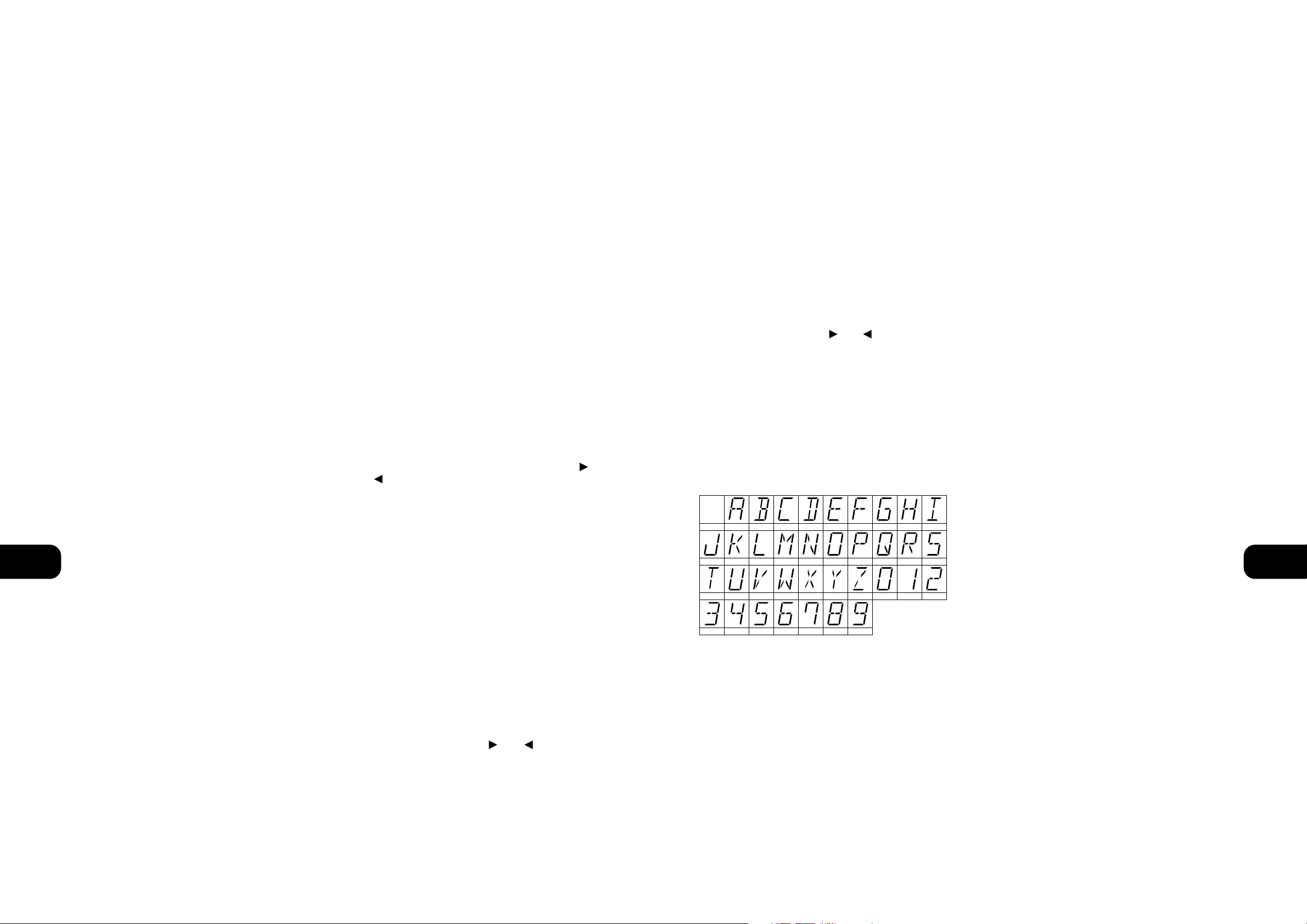
LABELLING A PRESET
When a station is transmitting RDS information, your NAD C730
will automatically show the station initials. Although the Tuner
automatically shows the frequency of any other AM or non-RDS
Preset station, it also allows you to type in the station name to
make it easier to identify which station is stored in the Memory
Preset. To enter a name:
1) Select the Preset you want to attach a name to.
2) Press and hold the Display button (No. 7) for two seconds. The
first space in the Station Data area of the Display Panel will
flash.
3) Press either the Tune/Preset or (No. 9) button to
scroll and select the first character (see Character list below
for reference).
4) Press Display to move one place to the right to enter the next
desired character.
5) Use the Tune/Preset buttons again to select the next character
in the name.
6) Repeat steps 3 to 5 until name is complete or all eight places
have been filled (up to 8 characters).
7) Press Memory once to finish the labelling procedure. Press
Memory again to store the completed name.
There are 37 characters available including a blank space.
NOTE: This function is only available for non-RDS stations. RDS
stations will always display their transmitted name and cannot be
over-written.
TO MAKE A RECORDING
When any source is selected, its signal is also fed directly to any
tape machine connected to the TAPE 1 or TAPE 2 OUTPUTS on the
rear panel for recording.
TAPE TO TAPE COPYING
You can copy between two tape machines connected to your NAD
C730. Put the source tape in the recorder connected to Tape 2 and
the blank tape into the recorder connected to Tape 1. By selecting
TAPE 2 Input, you can now record from Tape 2 to Tape 1 and
monitor the signal coming from the original tape.
REMOTE CONTROL HANDSET (FIG 4)
The Remote Control handset handles all the key functions of the
NAD C730 and has additional controls to remotely operate NAD
Tuners, Cassette and CD machines. It will operate up to a distance
of 16ft (5m). Alkaline batteries are recommended for maximum
operating life. Two AAA (R 03) batteries should be fitted in the
battery compartment at the rear of the Remote Control handset.
When replacing batteries, check that they have been put in the right
way round, as indicated on the base of the battery compartment.
Please refer to previous sections of the manual for a full
description of individual functions.
When a command from the remote control is received, the Standby/protection indicator will blink. Note that the indicator may also
blink when receiving commands not necessarily for the C730 but
for other components in the system.
1. STANDBY/ON BUTTON
When the amplifier is switched On, pressing the green On/Off
button on the remote handset will put the NAD-370 into Standby
mode and the Power indicator will turn amber. The amber Power
indicator shows that power is being supplied to the NAD-370, but
the system is currently in the Standby Mode. Press again to switch
the amplifier On from Stand-by mode.
2. POWER ON & OFF
Besides the On/Off toggle function of the green button (No. 1), the
NAD C730 remote also has a separate On and Off button. This can
be particularly useful to keep components within a system “insync”: This way all components will switch to stand-by when Off is
pressed or switch to operating mode when On is pressed, instead
of some components switching On when the amplifier is switched
to Stand-by. (Note that the other components have to be capable
of responding to the separate On and Off commands as well).
Press the ON button to switch the unit from Stand-by to the
operating mode; The Stand-by indicator (Fig. 2; No. 2) will turn
from amber to green and the indicator for the last selected input
will blink and light up. Press the OFF button to switch the unit to
the Stand-by mode: The Stand-by indicator will light up amber.
3. SPEAKERS A & B
These buttons are inoperative on the C730
4. MUTE
Press the MUTE Button (No. 4) to temporarily switch off the sound
to the speakers and headphones. Mute mode is indicated by
“MUTE” flashing in red in the display area. Press MUTE again to
restore sound. Mute does not affect recordings made using the
Tape outputs but will affect the signal going to the Pre-amp output
(Pre-Out).
5. INPUTS
The input selector buttons (No. 5) perform the same functions as
the buttons labelled the same on the front panel. There are a few
differences and extra functions with the remote control handset
however:
The TUNER AM & FM buttons select the Tuner input and
respectively the AM or FM waveband. The receiver will tune to the
last station selected on either AM or FM band.
NOTE: The Video 2 and Video 3 input selector buttons are
inoperative.
GB
9
13. INPUT SELECTORS
These buttons select the active input to the NAD C730 and the
signal sent to the loudspeakers, the Tape outputs and the PRE OUT
sockets. The buttons on the remote control handset duplicate
these buttons, with the exception of the tuner input; see below.
The display indicates which input has been selected.
DISC Selects a line-level source connected to the DISC sockets as
the active input.
CD Selects the CD (or other line-level source) connected to the
CD sockets, as the active input.
VIDEO Selects the VCR (or stereo TV/Satellite/Cable receiver)
connected to the VIDEO sockets, as the active input.
AUX Selects a line-level source connected to the AUX sockets, as
the active input.
TUNER Selects the tuner as the active input. The receiver will
return to the last selected preset or frequency. The remote control
handset has separate buttons for AM and FM; pressing either one
will select the tuner as the active input and revert to the last station
tuned to on respectively the AM or FM band.
TAPE 2 Selects Tape 2 as the active input.
TAPE 1 Monitor Selects the output from a tape recorder when
playing back tapes or monitoring recordings being made through
the Tape 1sockets. Press the Tape 1 button once to select it and
again to return to the normal input selection.
Tape 1 is a tape Monitor function which does not override the
current input selection. For example, if the CD is the active input
when TAPE 1 is selected, then the CD signal will continue to be
selected and sent to both the TAPE 1, and TAPE 2 OUTPUT sockets,
but it is the sound from recorder connected to Tape 1 that will be
heard on the loudspeakers. When Tape 1 Monitor is selected,
“TAPE 1” is indicated in the alphanumeric section of the display
for 3 seconds before it defaults to indicating the active input again.
The red box next to the preset number section in the display
indicating “TAPE MONITOR” will remain lit until Tape 1 is
disengaged again.
NOTE: The remote control handset with the C730 supplied is of a
universal NAD type, designed to operate several NAD models. Some
buttons on this handset are inoperative as the functions aren’t
supported by the C730. The Video 2, Video 3 input selector
buttons, tuner Bank button, speakers A and Speakers B buttons on
the remote control handset are inoperative in the case of the C730.
NOTE: Make certain that the volume control is turned to
minimum (fully anti-clockwise) before connecting or
disconnecting headphones. Listening at high levels can damage
your hearing.
14. BASS & TREBLE CONTROLS
The NAD C730 is fitted with BASS and TREBLE tone controls to
adjust the tonal balance of your system.
The 12 o’clock position is “flat” with no boost or cut and a detent
indicates this position. Rotate the control clockwise to increase
the amount of Bass or Treble. Rotate the control anti-clockwise to
decrease the amount of Bass or Treble. The Tone controls do not
affect recordings made using the Tape outputs but will affect the
signal going to the Pre-amp output (Pre Out).
15. TONE DEFEAT
The TONE DEFEAT switch by-passes the tone control section of the
NAD C730. If the Tone Controls are not normally used and left in
the 12 o’clock position, then it is advisable to switch out the Tone
Control section altogether by using this switch. In the “out”
position, the Tone Control circuits are active, pushing the TONE
DEFEAT switch “in” bypasses the Tone Control section.
16. BALANCE
The BALANCE control adjusts the relative levels of the left and right
speakers. The 12 o’clock position provides equal level to the left
and right channels. A detent indicates this position.
Rotating the control clockwise moves the balance towards the
right. Rotating the control anti-clockwise moves the balance to the
left. The BALANCE control does not affect recordings made using
the Tape outputs but will affect the signal going to the Pre-amp
output (Pre Out).
STORING, RECALLING
AND LABELLING PRESETS
Up to 30 presets in total can be stored in the C730’s memory bank;
these can be any mix of either AM or FM stations. When scrolling
through the presets, empty preset places will be skipped; it is thus
possible to go from preset No. 4 to No. 7 without having seen No.
5 and 6. With the presets you can also store whether you want
Blend (No. 3) and FM Mute/Mode (No. 5) to be activated as well
every time you recall the preset.
TO STORE A PRESET
• Tune to the radio station you wish to enter into a Preset (refer
to this chapter’s section 9). If the station is transmitting RDS
information, the RDS indicator will light up and station initials
or name will be shown in the Display Panel. If a non-RDS
station is found, then just the frequency will be shown.
• Select Blend (No. 3) or FM Mute/Mode (No. 5) if desired.
• To store that station as a Preset, press Memory (No. 4). The
Preset number and the red “MEMORY” indicator are flashing
in the Display Panel. The lowest available empty preset number
will be shown. If no other buttons are pressed within 8
seconds, the tuner will revert to its previous state.
• Press Memory again to store the preset. If you wish to assign a
different preset number, press either the Preset/Tune or
button to select the desired preset number. You can overwrite an existing preset. If the preset number already has been
assigned, “MEMORY” will stop blinking, but the preset will
continue to blink. When you have selected the desired preset
number, press Memory again to store the station.
NOTES: You can enter a new station into an unused Preset or
over-write an existing programmed Memory Preset. By doing this
you will replace all the data previously held on that Preset number.
When Memory is pressed during normal operation, the Preset
number and the red “MEMORY” indicator will flash in the Display
Panel. If no other buttons are pressed within 8 seconds, the tuner
will revert to its previous state. The Memory Presets have a memory
back-up, so they will remain stored for several weeks even if the
Tuner is switched off or unplugged from the mains supply.
RECALLING A PRESET
• To select a Preset station, check if Preset mode is engaged (the
display indicates “PRESET”). If not, press the Preset/Tune
Mode button (No. 8); “PRESET” will now light up in the
display.
• Press either the Preset/Tune or buttons (No. 9)
until the right Preset is found and shown in the Display Panel.
Any unused Presets will be skipped; this avoids having to scroll
through empty presets.
GB
8
SPACE
A B C D E F G H I
J K L M N O P Q R S
T U V W X Y Z 0 1 2
3 4 5 6 7 8 9
Page 6

GB
11
GB
10
TROUBLESHOOTING
NO SOUND • Power AC lead unplugged or power not
switched on
• Tape 2 Monitor selected
• Mute on
• Rear Pre-out/Main-in amp links not
fitted
• Speakers not switched on
• Check if AC lead is plugged in and
power switched on
• De-select Tape 2 Monitor mode
• Switch off Mute
• Fit links
• Switch Speakers A or B on
NO SOUND ONE CHANNEL • Balance control not centered
• Speaker not properly connected or
damaged.
• Input lead disconnected or damaged
• Center Balance control
• Check connections and speakers
• Check leads and connections
REMOTE CONTROL HANDSET
NOT WORKING
• Batteries flat, or incorrectly inserted
• IR transmitter or receiver windows
obstructed
• IR receiver in direct sun or very bright
ambient light
• Check or replace batteries
• Remove obstruction
• Place unit away from direct sun, reduce
amount of ambient light
NO SOUND WITH TUNER • Antenna leads incorrectly connected
• Station not selected or weak signal with
FM Mute on.
• Internal fuse blown
• Check antenna connections to receiver
• Re-tune or switch off FM Mute
• Consult dealer
Problem Cause Solution
WEAK BASS/DIFFUSE STEREO IMAGE • Speakers wired out of phase • Check connections to all speakers in
the system
NOISE, HISS ON AM AND FM • Weak signal • Check station tuning. Adjust or replace
antenna.
DISTORTION ON FM • Multi-path signals or interference from
another station
• Check station tuning. Adjust or replace
antenna
WHISTLES OR BUZZES ON FM & AM • Interference from other electrical
sources - computers, games consoles
• Check station tuning. Switch off or
move the source of the electrical noise
WHISTLES OR BUZZES ON AM • Interference from fluorescent lighting
or electrical motors
• Check station tuning. Adjust or replace
AM antenna
NO RDS INFORMATION • Station signal too weak.
• Station not transmitting RDS data
• Check station tuning. Adjust or replace
antenna
• No remedy
6. MASTER VOLUME
Press the MASTER VOLUME or (No. 7) buttons to
increase, respectively decrease the loudness level. Release the button
when the desired level is reached. The motorised Volume Control on
the front panel will indicate the level set. The Master Volume buttons
do not affect recordings made using the Tape outputs but will affect
the signal going to the Pre-amp output (Pre-Out).
7. TUNER CONTROL BUTTONS
PRESET or selects respectively higher or lower number
station preset.
The BANK button is inoperative on the C730.
8. CD PLAYER CONTROL BUTTONS
(for use with NAD CD Player).
engages Pause
engages Stop
engages Play or toggles between Play and Pause
or engages Track skip; Press once to respectively go
to the next track or to return to start of current or previous track.
NEXT DISC Go to next disc (for NAD CD changers).
9. CASSETTE DECK CONTROL BUTTONS
(for use with single (DECK B) or double transport (A and B)
NAD Cassette Decks).
or engages Forward Play or Reverse Play.
Record/Pause. Press to put cassette deck into record-pause.
Press Play to start recording.
Stops Play or Recording.
engages Rewind.
engages Fast Forward.
NOTES: The remote control handset supplied with the C730 is of
a universal NAD type, designed to operate several NAD models.
Some buttons on this handset are inoperative, as the functions
aren’t supported by the C730. The Video 2, Video 3 input selector
buttons (inside section 5), tuner Bank button (section 7),
speakers A and Speakers B buttons (section 3) on the remote
control handset are inoperative in the case of the C730.
Direct sunlight or very bright ambient lighting may affect the
operating range and angle for the remote control handset.
The infrared remote control command receiver, located on the far
left of the display window, receives commands from the remote
control. There must be a clear line-of-sight path from the remote
control to this window; if that path is obstructed, the remote
control may not work.
Page 7

“ENTREE MAGNETOPHONE 1” (TAPE 1 IN) pour la lecture et le
contrôle d’enregistrement des bandes. Reliez les connecteurs d’
“Entrée Audio” gauche et droit du magnétophone aux prises de
“SORTIE MAGNETOPHONE 1” (TAPE 1 OUT) pour
l’enregistrement des bandes.
9. SORTIE PREAMPLI (PRE OUT)
Le NAD C730 permet la connexion d’un amplificateur de
puissance supplémentaire ou différent. Si vous souhaitez
connecter un amplificateur de puissance stéréophonique externe,
utilisez un câble jumelé RCA vers RCA pour relier les “Entrées
Audio” gauche et droite de l’Ampli de Puissance aux connecteurs
de “SORTIE PREAMPLI 1” (PRE OUT 1).
NOTES: Vous devez toujours mettre hors tension le C730 ainsi
que tous les amplificateurs de puissance extérieurs avant de
brancher ou de débrancher quoi que ce soit aux connecteurs de
“SORTIE PREAMPLI” (PRE OUT). Le signal de sortie
préamplificateur Pre-Out sera affecté par les réglages de volume
et de tonalité du NAD C730.
10. ENTREE/SORTIE LIAISON-NAD (NAD-LINK
IN, OUT)
Le connecteur de “Liaison-NAD” (NAD-Link) sert à relayer les
commandes en provenance d’autres appareils équipés de
connecteurs de Liaison-NAD. Ceci permet de commander le
système entier depuis un point central, et assure aussi quelques
fonctions de base pour d’autres composants NAD (tels que le
tuner, le lecteur de CD ou le lecteur de cassettes) pourvus
également d’une liaison NAD qui est commandée par la
télécommande du récepteur. Pour assurer le relais vers d’autres
appareils, reliez le connecteur de “SORTIE Liaison-NAD” (NADLink OUT) du C730 à l’ “ENTREE Liaison-NAD” (NAD-Link IN) de
l’autre appareil. Il est possible de relier les connecteurs de
Liaison-NAD en chaîne, ENTREE vers SORTIE, et donc de
commander tout un réseau d’appareils à l’aide de la
télécommande d’un seul d’entre eux.
NOTES: Il est conseillé de ne pas connecter la Liaison-NAD si ces
appareils comportent leur propre récepteur de télécommande
intégré et qu’ils sont situés au même endroit, à portée directe de
la télécommande. En cas de doute, commencez par essayer de
faire fonctionner les appareils sans la Liaison-NAD; si l’appareil
réagit à la commande émise par le combiné de télécommande, il
ne sera pas nécessaire de connecter la Liaison-NAD.
Ne reliez jamais le dernier appareil de la chaîne Liaison-NAD au
premier. Débranchez tous les appareils du secteur avant de
brancher ou de débrancher la Liaison-NAD.
11. ECRETAGE DOUX (SOFT CLIPPING™)
Lorsqu’un amplificateur est poussé au-delà de sa puissance de
sortie spécifiée, on entend un son dur et déformé lors des
passages à sonorité forte. Cela provient du fait que l’amplificateur
coupe ou “écrête de façon dure” les pointes sonores pour
lesquelles sa conception ne permet pas la reproduction. Le circuit
d’écrêtage doux, de NAD, limite en douceur la forme d’onde à la
sortie, pour minimiser la distorsion audible lorsque
l’amplificateur est poussé au-delà de ses limites.
Si votre écoute comporte des niveaux modérés de puissance, vous
pouvez laisser l’Ecrêtage Doux sur “ARRET” (OFF). Si, par contre,
vous pensez passer de la musique à des niveaux très élevés,
susceptibles de dépasser la capacité de puissance de
l’amplificateur, nous préconisons de mettre l’Ecrêtage Doux sur
“MARCHE” (ON).
12. SORTIE ASSERVISSEMENT 12 V
(12 V TRIGGER)
Cette sortie permet de télécommander la mise en marche ou l’arrêt
d’appareils auxiliaires comme par exemple un tuner, un
amplificateur de puissance, etc…, dans la mesure où ces appareils
sont aussi équipés d’une entrée d’asservissement 12 V. Il est aussi
possible de télécommander une barrette de prises secteur équipée
d’une entrée d’asservissement 12 V. La sortie d’asservissement 12
V est activée chaque fois que l’appareil est commuté en mode de
fonctionnement normal à partir du mode Veille ou Arrêt.
Pour commuter un appareil externe entre les modes Veille et
Marche, à travers le C730, branchez la sortie asservissement 12 V
du C730 au jack d’entrée CC de l’appareil concerné. Le connecteur
requis est une fiche Mini-Jack standard de 3,5 mm (“mono”):
L’extrémité de la fiche jack correspond au “+” et la tige correspond
à l’asservissement 12 V, c’est à dire au “-” ou à la masse.
NOTES: Vérifiez les spécifications de la borne d’entrée
d’Asservissement sur les autres appareils pour vous assurer de leur
compatibilité avec la sortie Asservissement 12 V du C730. Tous les
appareils NAD équipés d’un Asservissement 12 V sont entièrement
compatibles avec la sortie Asservissement 12 V du C730.
La tension de sortie de l’Asservissement 12 V du C730 est de 12 V
CC. Le courant total maximum consommé ne doit pas dépasser
200 mA. Typiquement, les asservissements 12 V NAD consomment
un courant inférieur à 10 mA. Avant de réaliser un quelconque
branchement à une entrée ou à une sortie d’Asservissement 12 V,
assurez-vous que tous les appareils sont débranchés du secteur.
Tout non respect de la consigne ci-dessus pourrait provoquer la
détérioration du C730 ou de tout appareil auxiliaire qui lui est
connecté. En cas de doute concernant les branchements,
l’installation et l’utilisation de la sortie d’Asservissement 12 V,
consultez votre revendeur NAD.
13. HAUT-PARLEURS
Branchez le haut-parleur droit sur les bornes repérées “R+” et
“R-”, en vous assurant que le “R+” est relié à la borne “+” de
votre haut-parleur et que “R-” est relié à la borne “-” de votre
haut-parleur. Branchez les bornes repérées “L+” et “L-” au hautparleur gauche en procédant de la même manière.
N’utilisez que du fil torsadé haute puissance (calibre 16; 1,5 mm
ou plus) pour brancher les haut-parleurs à votre NAD C730.
Il est possible d’utiliser les bornes pour courants élevés comme
bornes à visser pour les câbles comportant des cosses plates, des
broches ou des fils nus.
FILS NUS ET BORNES A BROCHES
Les fils nus et les broches s’insèrent dans le trou diamétral percé
dans la tige de la borne. Desserrez la bague en plastique de la
borne de haut-parleur jusqu’à ce que le trou axial dans la tige soit
visible. Insérez la broche ou le fil nu dans le trou, puis fixez le
câble en vissant la bague de la borne.
Veillez à ce qu’aucun fil nu des câbles des haut-parleurs ne touche
le panneau arrière ou une autre prise. Veillez à ce qu’il n’y ait que
1 cm (1/2”) de fil nu ou de broche et qu’il n’y ait aucun brin libre
sur les fils des haut-parleurs.
NOTA: Assurez-vous que l’impédance des haut-parleurs est d’au
moins 4 ohms si vous ne connectez qu’une paire de haut-parleurs
; assurez-vous que l’impédance de tous les haut-parleurs est d’au
moins 8 ohms si vous connectez deux paires de haut-parleurs.
F
13
MISE EN MARCHE RAPIDE
1. Connectez les haut-parleurs aux bornes Haut-Parleurs et
connectez les sources aux prises d’entrées appropriées à
l’arrière de l’appareil.
2. Branchez le cordon d’alimentation secteur.
3. Appuyez sur le bouton-poussoir “ALIMENTATION” (POWER]
pour mettre le NAD C730 sous tension.
4. Appuyez sur le sélecteur d’entrée requis.
5. Pour écouter la radio, connectez l’antenne AM et FM.
6. Appuyez sur le bouton-poussoir AM/FM pour sélectionner la
réception sur la bande AM ou FM.
7. Appuyez sur le bouton de Préréglage/Accordage (Preset/Tune]
de manière à éteindre le mot Préréglage (PRESET] sur
l’affichage ; le tuner est alors en mode Tune.
8. Utilisez les boutons fléchés de préréglage/accordage
PRESET/TUNE ou pour trouver une station.
NOTES CONCERNANT L’INSTALLATION
Posez le NAD C730 sur une surface stable, plane et horizontale.
Evitez les rayons directs du soleil et les sources de chaleur et
d’humidité. Assurez une ventilation adéquate. Ne posez pas cet
appareil sur une surface molle (moquette, par exemple). Ne le
placez pas dans un endroit confiné (sur une étagère de bibliothèque
ou derrière des portes vitrées), où le flux d’air à travers les ouïes de
ventilation risque d’être entravé. Vérifiez que l’appareil est mis hors
tension avant de réaliser des connexions quelconques.
Pour vous faciliter la tâche, les bornes RCA de votre NAD C730
sont codées couleur. Rouge pour l’audio droite, blanc pour
l’audio gauche, et jaune pour la Liaison-NAD. N’utilisez que des
câbles et des connecteurs de très bonne qualité de manière à
obtenir un branchement dont la fiabilité est parfaite et les
performances optimales. Vérifiez que les câbles et les connecteurs
ne présentent aucune détérioration, et que tous les connecteurs
sont bien enfoncés jusqu’en butée.
Pour obtenir les meilleures performances, utilisez des câbles de hautparleurs d’une épaisseur égale ou supérieure au calibre 16 (1,5
mm). Si l’appareil doit rester inutilisé pendant un certain temps,
débranchez le cordon d’alimentation de la prise de secteur murale.
Si de l’eau pénètre à l’intérieur de votre NAD C730, coupez
l’alimentation de l’appareil et retirez la fiche de la prise secteur.
Faites contrôler l’appareil par un technicien de service après-vente
qualifié, avant toute tentative de remise en service. Ne retirez pas
le couvercle. A l’intérieur, il n’y a aucun élément sur lequel
l’utilisateur peut intervenir. Utilisez un chiffon doux sec et
propre pour nettoyer l’appareil. Si nécessaire, humectez le chiffon
avec un peu d’eau savonneuse. N’utilisez pas de solution contenant
du benzol ou un quelconque autre agent volatile.
BRANCHEMENTS SUR LE PANNEAU ARRIERE
(FIGURE 1).
1. ANTENNE FM
Une antenne filiaire FM, sous forme de câble plat, est livrée avec
le C730. Cette antenne se branche à l’arrière de l’appareil à l’aide
de l’adaptateur “balun” fourni (Cf. Figure 2). L’antenne câble plat
doit être fixée sur une surface verticale, et doit former un “T”.
Faites des essais en mettant l’antenne dans différentes positions,
de manière à obtenir le meilleur signal possible avec un minimum
de bruit de fond. Un signal FM insuffisant entraîne beaucoup de
sifflements, surtout en réception stéréophonique, et de
l’interférence en provenance de sources électriques externes.
Dans les endroits où la réception FM est faible, il est possible
d’améliorer les performances du tuner en utilisant une antenne
FM montée à l’extérieur du bâtiment. Un installateur d’antennes
qualifié pourra vous donner les conseils appropriés, et poser une
antenne adaptée aux conditions de réception locales.
2. ANTENNE AM
Une antenne cadre AM est livrée avec le NAD C730 et permet de
recevoir les stations émettant sur la bande AM. Pour brancher
l’antenne AM, il faut d’abord pousser les clés sur les bornes
d’antenne vers le bas. Insérez les fils d’antenne nus dans les trous
des deux bornes et poussez les clés des bornes vers le haut pour
assurer la connexion (Cf. Figure 2).
Faites des essais en mettant l’antenne dans différentes positions,
mais en vous assurant que le cadre est toujours vertical afin que la
réception soit optimale. Le fait de positionner l’antenne à proximité
d’éléments métalliques de taille importante, comme des étagères en
métal ou des radiateurs par exemple, peut affecter la réception.
3. ENTREE DISQUE
Entrée pour les signaux d’entrée supplémentaires de niveau ligne,
tels qu’un lecteur CD, un lecteur Mini-Disc ou le signal de sortie
provenant d’un amplificateur de rehausseur pour tourne-disques.
Utilisez un câble jumelé RCA vers RCA pour relier les connecteurs
de “Sortie Audio” (Audio Outputs] gauche et droit de l’appareil
audio auxiliaire à cette entrée.
4. ENTREE CD
Entrée pour un lecteur CD ou pour toute autre source de signal de
niveau ligne. Utilisez un câble jumelé RCA vers RCA pour relier les
connecteurs de sortie audio gauche et droit du lecteur CD à cette entrée.
Le NAD C730 n’accepte que les signaux analogiques de votre lecteur CD.
5. ENTREE VIDEO
Entrée pour le signal audio provenant d’un magnétoscope stéréo (ou
TV stéréo/Satellite/Récepteur de télédistribution) ou d’une autre
source audio de niveau ligne. Utilisez des câbles jumelés RCA vers
RCA pour relier les connecteurs de “Sortie Audio” gauche et droit de
l’appareil à ces entrées. Nota : Il s’agit d’entrées audio uniquement.
6. ENTREE AUX
Entrée pour d’autres signaux de niveau ligne, comme un deuxième
lecteur CD par exemple. Utilisez un câble jumelé RCA vers RCA
pour relier les connecteurs de “Sortie Audio” (Audio Outputs]
gauche et droit de l’appareil audio auxiliaire à cette entrée.
7. ENTREE/SORTIE MAGNETOPHONE 2
(TAPE 2 IN, OUT)
Branchements pour enregistrement et lecture analogiques sur un
magnétophone audio de type quelconque. Utilisez des câbles jumelés
RCA vers RCA pour relier les connecteurs de “Sortie Audio” gauche
et droit du magnétophone aux prises d’ “ENTREE MAGNETOPHONE
2” (TAPE 2 IN) pour la lecture et le contrôle d’enregistrement des
bandes. Reliez les connecteurs d’ “Entrée Audio” gauche et droit du
magnétophone aux prises de “SORTIE MAGNETOPHONE 2” (TAPE 2
OUT) pour l’enregistrement des bandes.
8. ENTREE/SORTIE MAGNETOPHONE 1
(TAPE 1 IN, OUT)
Branchements pour enregistrement et lecture analogiques sur un
deuxième magnétophone audio de type quelconque. Utilisez des
câbles jumelés RCA vers RCA pour relier les connecteurs de
“Sortie Audio” gauche et droit du magnétophone aux prises d’
F
12
Recepteur Stereo AM/FM NAD C730
Page 8

NOTA: Il est possible de mettre en mémoire l’état Silencieux FM/Mode
FM individuellement pour chaque station préréglée. Reportez-vous au
chapitre spécifique intitulé “Mise en mémoire, rappel et désignation
des stations préréglées” pour plus d’informations.
6. AM/FM
Le bouton AM/FM permute le tuner entre la bande AM et la bande
FM et vice versa. L’affichage signale la fréquence de la station
accordée et la bande sélectionnée. L’accordage FM se fait en
accroissements de 0,05 MHz tandis que l’accordage AM se fait en
accroissements de 9 ou 10 kHz, tout selon la version.
7. AFFICHAGE
Pour les stations offrant des informations RDS, le bouton
d’Affichage (Display) fait défiler trois différents modes d’affichage
et chaque impulsion de bouton successif active le mode suivant
parmi les trois modes:
a) En mode “par défaut” (default), l’affichage indique le nom
RDS de la station, “Service Programme” (Program Service)
(PS; normalement le sigle d’une station, p.ex. BBC R3).
b) En partant de ce mode par défaut, appuyez une fois sur le bouton
pour afficher le Radio Texte (RT). Ceci peut offrir des informations
supplémentaires, comme par exemple le nom du présentateur ou
du programme, la chanson qui passe, etc. Ce texte défile en
continu sur les 8 segments de l’affichage alphanumérique.
c) Appuyez sur le bouton du mode d’affichage RT pour afficher la
fréquence de la station. Réappuyez pour retourner au mode
par défaut (a).
Accordage sur une station sans RDS
Le bouton d’affichage (Display) bascule l’affichage pour afficher
soit la fréquence de la station, soit le nom de station entré par
l’utilisateur. Si aucun nom d’utilisateur n’a été entré, l’affichage
indique “PAS DE RDS” (NO RDS).
Le bouton d’Affichage (Display) permet aussi d’enregistrer une
désignation pour les stations non RDS. Reportez-vous au chapitre
spécifique intitulé “Mise en mémoire, rappel et désignation des
stations préréglées” pour plus d’informations.
8. PRE-REGLAGE/ACCORDAGE (PRESET/TUNE)
Le bouton de Préréglage/Accordage (Preset/Tune) permute entre
deux modes différents:
a) Mode Station Préréglée (Preset): Dans ce mode, vous pouvez
utiliser les boutons de Préréglage/Accordage (Preset/Tune)
(No. 9) pour choisir une station préréglée. Lorsque le mode
de Préréglage est sélectionné, le mot PREREGLAGE (PRESET)
défile une fois sur l’affichage, puis le témoin de PREREGLAGE
(PRESET) s’allume sur l’affichage. (????Where )
b) Mode “Accordage” (Tune): En appuyant sur les boutons de
Préréglage/Accordage (Preset/Tune) (N° 9) ou , il
est possible de lancer un accordage automatique ou manuel
qui balaye la bande de fréquences dans le sens montant ou
descendant. Lorsque le mode d’Accordage est sélectionné, le
mot “TUNE” (ACCORDAGE) défile une fois sur l’affichage.
9. PRÉRÉGLAGE/ACCORDAGE ET
(PRESET/TUNE ET )
La fonction de ces boutons dépend du mode d’accordage
sélectionné grâce au bouton de Préréglage/Accordage
(Preset/Tune) (N° 8). Le bouton de Préréglage/Accordage
permute entre les deux modes de fonctionnement:
a) Mode “Station Préréglée” (Preset) (indiqué sur l’affichage):
Appuyez sur le bouton (bas) pour défiler jusqu’à une
Station Préréglée ayant un numéro inférieur; appuyer sur le
bouton (haut) pour faire le défilement jusqu’à une
Station Préréglée ayant un numéro plus élevé. Il s’agit d’une
fonction “circulaire”, ce qui veut dire qu’après avoir atteint le
numéro de préréglage le plus élevé, le tuner passe ensuite au
numéro le plus bas, ou inversement, suivant si l’on fait défiler
les chiffres avec le bouton haut ou bas.
b) Mode “Accordage” (Tune) : Appuyez sur le bouton (bas)
ou sur le bouton (haut) pendant plus de 1 seconde pour
lancer l’accordage automatique en balayant la bande de
fréquences respectivement vers le haut ou vers le bas. Le tuner
recherche automatiquement la première station dont le signal
est suffisamment puissant et il s’arrête là. Appuyez à nouveau
sur le bouton Bas/Haut pendant plus de 1 seconde pour
reprendre la recherche de stations.
En donnant de brèves impulsions sur les boutons (bas) ou
(haut), vous pouvez effectuer un accordage manuel,
respectivement vers le bas ou vers le haut de la bande de fréquences,
de manière à accorder le tuner sur une fréquence spécifique. Pour
chaque impulsion sur la touche concernée, le tuner effectuera un
saut de 0,05 MHz sur la bande FM, de manière à ce qu’il vous soit
possible de d’accorder avec précision sur la fréquence que vous
souhaitez. Pour la bande AM, les pas d’accordage sont de 10 kHz
(version 120 V) ou de 9 kHz (version 230 V).
Ce mode d’accordage peut aussi être utile quand il s’agit de
recevoir une station radio trop faible pour être captée par le mode
de recherche automatique. Lorsque la station est accordée de
façon précise, TUNED (Accordée) s’allume sur l’affichage. Le
circuit de silencieux peut néanmoins supprimer les signaux de
stations très faibles. Si une station très faible émet en stéréo, la
réception se fera avec un important sifflement de fond. Le fait de
passer en Mode Mono et de désactiver le circuit de silencieux en
appuyant sur le bouton SILENCIEUX DE RECHERCHE FM/MODE
FM (FM MUTE/MONO) (N° 5) permettra d’entendre la station et
éliminera tout ou la plupart de ce bruit de fond.
NOTES: L’accordage automatique fonctionne aussi bien en FM qu’en AM.
Même si le C730 est en Mode d’Accordage, les boutons “Préréglage Haut”
(Preset Up) et “Préréglage Bas” (Preset Down) de la télécommande
n’auront pour seul effet que de changer de station préréglée.
Les boutons fléchés de Préréglage/Accordage (Preset/Tune
et ) s’utilisent aussi avec les boutons de Mémoire (Memory)
(N° 4) et d’Affichage (Display) (N° 7) pour ajouter et mettre en
mémoire des désignations pour les stations préréglées, ces
désignations étant définies par l’utilisateur. Reportez-vous au
chapitre spécifique intitulé “Mise en mémoire, rappel et
désignation des stations préréglées” pour plus d’informations.
10. ZONE D’AFFICHAGE
La zone d’affichage vous permet de voir toutes les informations
essentielles concernant l’état du récepteur. Les informations
suivantes sont affichées:
• L’entrée sélectionnée
• Si le Silencieux de Volume (MUTE) est actif
• Si le Moniteur de Bande (Tape Monitor) est actif
• Si la Tonalité Neutre (Tone Defeat) est active
• La bande et la fréquence de la station sélectionnée, RDS PS
(nom de la station), ou RDS Radio Text. RDS Radio Text n’est
affiché que si le RDS est disponible; La sélection se fait à l’aide
du bouton d’Affichage (Display) (N° 7).
• FM Stereo, si l’émission captée est en FM Stéréo
• Si la station FM émet ou non des signaux RDS.
• Si la fonction Mémoire (Memory) a été activée.
• Le numéro de la station préréglée, si la station en cours de réception
a été mise en mémoire dans la banque de mémoire du tuner.
• Fondu (Blend) et Silencieux FM/Mode FM (FM Mute/Mode) si
ces fonctions sont actives.
F
15
14. CORDON ALIMENTATION SECTEUR
Branchez le cordon secteur à une prise de courant murale en état
de marche. Veillez à ce que tous les branchements aient été faits
avant de brancher le cordon au secteur.
15. PRISE SECTEUR AUXILIAIRE COMMUTEE
Le cordon secteur d’un autre appareil pourra être branché sur cette
prise auxiliaire. Les appareils branchés sur cette prise seront
commutés entre Marche et Arrêt par le bouton d’ “ALIMENTATION”
(POWER) sur la face parlante, ou par les boutons “MARCHE” (ON)
et “VEILLE” (STAND-BY) de la télécommande.
NOTA: La consommation totale de tous les modules connectés
aux sorties secteur ne doit pas dépasser 100 Watts.
COMMANDES SUR LA FACE PARLANTE
1. MARCHE/ARRET (POWER ON/OFF)
Appuyez sur le bouton “MARCHE” (POWER) pour mettre le
récepteur sous tension. La lampe témoin de “Veille” (Stand-by)
(N° 2) au dessus du bouton Marche s’allume en rouge puis, après
un court laps de temps, passe au vert pour indiquer que
l’amplificateur est prêt à fonctionner normalement.
Le fait d’appuyer à nouveau sur le bouton “MARCHE” (POWER) mettra
l’appareil complètement hors tension ; il ne réagira plus à la télécommande.
TELECOMMANDE (CF. FIGURE 4)
BOUTON VEILLE/MARCHE (STANDBY/ON) (N° 1)
Lorsque l’amplificateur est sous tension (“MARCHE” (POWER)), le fait
d’appuyer sur le bouton vert Marche/Arrêt du combiné de
télécommande fait passer le NAD C730 en mode Veille et la lampe témoin
“Marche” (Power) passe à l’orange. La lampe témoin orange
d’Alimentation (Power) indique que la chaîne est sous tension, mais
qu’elle est actuellement en mode Veille. Appuyez à nouveau sur ce bouton
pour mettre le récepteur en mode Marche à partir du mode Veille.
Boutons “MARCHE” (ON) et “ARRET” (OFF) (N° 2):
En plus de la fonction de permutation Marche/Arrêt du bouton
vert (N° 1), le NAD C730 comporte aussi un bouton Marche et
Arrêt distinct. Ceci est particulièrement utile pour maintenir la
synchronisation des appareils constituant la chaîne: De cette
manière, tous les appareils passeront en mode Veille lorsque vous
appuierez sur “Arrêt” (Off), ou passeront en mode Marche
lorsque vous appuierez sur “On” (Marche), plutôt que de se
mettre en Marche lorsque vous mettrez le récepteur en mode
Veille. (A noter que les autres appareils doivent eux aussi être
capables de répondre à des commandes de Marche/Arrêt
distinctes). Appuyez sur le bouton “Marche” (ON) pour faire
passer l’appareil du mode Veille au mode de fonctionnement; La
lampe témoin Veille (Stand-by) (Fig. 2; N° 2) passera de l’orange
au vert pour indiquer que le récepteur est prêt à fonctionner.
Appuyez sur le bouton OFF pour mettre l’appareil en mode Veille
: la lampe témoin de Veille passera à l’orange.
NOTA: Le C730 ne consomme que très peu de courant en mode
Veille. Toutefois, si l’appareil doit rester inutilisé pendant plusieurs
jours, nous préconisons de le mettre hors tension. Pour mettre
l’appareil hors tension, appuyez sur le bouton “Marche-Arrêt”
(POWER) (N° 1) de la face parlante; tous les voyants s’éteindront.
2. LAMPE TEMOIN DE VEILLE
Cette lampe témoin s’allume en vert lors d’un fonctionnement
normal. En mode Veille, la lampe témoin s’allume en orange.
Reportez-vous à la section 1 de ce même chapitre pour de plus
amples informations. La lampe témoin clignote lorsque le
récepteur reçoit une télécommande envoyée par le combiné de
télécommande fourni avec l’appareil.
Si le récepteur se met en mode de “protection”, la LED clignote
de façon permanente à une vitesse de deux coups par seconde.
Cela arrive, par exemple, si un court-circuit se produit dans le
câblage des haut-parleurs. Eteignez complètement l’appareil en
appuyant sur le bouton d’Alimentation (Power) (N° 1) sur la face
parlante, puis vérifiez tous les câbles et toutes les connexions
aussi bien du côté récepteur que du côté haut-parleurs. Après
avoir remis les branchements en état, allumez l’appareil à l’aide
du bouton d’Alimentation (Power) (N° 1), après avoir réglé la
commande de volume au minimum, puis reprenez une utilisation
normale. Si le problème persiste, désalimentez complètement
l’appareil et consultez votre revendeur.
3. FONDU (BLEND)
Certaines stations radio stéréo faibles ou éloignées sont parfois
captées avec du bruit ou des sifflements dus à un signal d’antenne
trop faible. Vous pouvez atténuer le bruit et les sifflements en
mettant le tuner sur mono, mais cet apport de qualité d’écoute se
fait aux dépens de la stéréophonie. La fonction “Fondu” (Blend)
de NAD, quant à elle, vous permet d’atténuer le bruit et les
sifflements tout en gardant un certain niveau de séparation
stéréophonique, plutôt qu’une monophonie totale. Le bouton
Fondu (Blend) permute entre le mode Fondu (Blend) et le mode
stéréophonique normal; lorsque celle-ci est activée, l’indicateur
de FONDU (BLEND) s’allume sur l’affichage.
NOTA: L’état d’activation de la fonction “Fondu” peut être mis en
mémoire en même temps que les différentes stations préréglées.
Reportez-vous au chapitre spécifique intitulé “Mise en mémoire, rappel
et désignation des stations préréglées” pour plus d’informations.
4. MEMOIRE (MEMORY)
La Mémoire est utilisée pour stocker des stations dans la banque
de Mémoire des Stations Préréglées, ainsi que pour stocker des
désignations définies par l’utilisateur pour les stations préréglées
non RDS. Lorsque vous appuyez sur le bouton Mémoire
(Memory) pendant le fonctionnement normal, le numéro de la
Station Préréglée et le témoin rouge MEMOIRE (MEMORY)
clignotent sur l’affichage. Si vous n’appuyez sur aucun autre
bouton pendant 12 secondes, le récepteur repasse à l’état qui était
actif avant d’appuyer sur MEMOIRE. Reportez-vous au chapitre
spécifique intitulé “Mise en mémoire, rappel et désignation des
stations préréglées” pour plus d’informations.
5. SILENCIEUX DE RECHERCHE FM/MODE FM
(FM MUTE/MODE)
Ce bouton combine deux fonctions; il commute la section tuner du
récepteur de Stéréo en Mono et désactive en même temps les circuits
du silencieux de recherche. Le circuit du silencieux de recherche
rend le tuner silencieux entre les stations radio lors de la recherche
ou de l’accordage. Ceci permet d’éviter le bruit d’accordage.
Il arrive cependant que le circuit silencieux élimine les signaux de
stations radio très faibles. Si une station faible est en mode stéréo,
vous entendrez un sifflement de fond important. Le fait de changer
en mode Mono et de désactiver le circuit du silencieux de
recherche en appuyant sur le bouton “Silencieux FM/Mode FM”
(FM MUTE/MODE) vous permet d’entendre la station et d’annuler
tout ou la plupart du bruit de fond. En fonctionnement normal, le
circuit du silencieux de recherche est activé et l’affichage indique
“Silencieux FM” (FM MUTE). Appuyez sur le bouton “Silencieux
FM/Mode FM” (FM Mute/Mode) pour désactiver le circuit du
silencieux et pour changer la réception stéréo en réception mono.
Le voyant du “Silencieux FM” (FM MUTE) s’éteint sur l’affichage.
Réappuyez sur le bouton “Silencieux FM/Mode FM” (FM
Mute/Mode) pour retourner à l’état Auto-Stéréo-FM.
F
14
Page 9

MISE EN MEMOIRE, RAPPEL ET DESIGNATION
DES STATIONS PREREGLEES (PRESETS)
Il est possible de stocker jusqu’à 30 stations préréglées dans la
banque de mémoire du C730; il peut s’agir de n’importe quel
panachage de stations AM ou FM. Lorsque vous faites défiler les
stations préréglées, les emplacements non utilisés sont sautés.
Cela veut dire qu’il est possible de passer de la station préréglée
N° 4 à la N° 7, sans pour autant voir passer la N° 5 et la N° 6 si
elles ne contiennent aucune station préréglée
En mettant en mémoire vos stations préréglées, vous pouvez aussi
préciser si vous voulez que les modes Fondu (Blend) (N° 3) et/ou
Silencieux FM/Mode FM (N° 5) soient activés chaque fois que
vous choisissez telle ou telle station préréglée.
MISE EN MEMOIRE D’UNE STATION
PREREGLEE
• Accordez le tuner sur la station radio que vous voulez mettre
en mémoire (reportez-vous à la section 9 de ce même
chapitre). Si la station émet des informations RDS, le voyant
RDS s’allumera et les initiales ou le nom sera indiqué sur
l’affichage. Si le tuner repère une station sans RDS, seule la
fréquence sera affichée.
• Sélectionnez les modes Fondu (Blend) (N° 3) et/ou Silencieux
FM/Mode FM (N° 5), si vous le souhaitez.
• Pour mettre cette station en mémoire comme une station
préréglée, appuyer sur le bouton “Mémoire” (MEMORY) (N° 4).
Le numéro de la station préréglée et le témoin rouge MEMOIRE
(MEMORY) clignotent sur le panneau d’affichage. Le numéro de
station préréglée libre le moins élevé s’affiche. Si vous n’appuyez
sur aucun autre bouton pendant 8 secondes, le tuner repasse à
l’état qui était actif avant d’appuyer sur MEMOIRE.
• Appuyez à nouveau sur Mémoire (Memory) pour mettre la
station en mémoire. Si vous souhaitez affecter un numéro de
préréglage différent à la station, appuyez sur l’un des boutons
de Préréglage/Accordage (Preset/Tune) ou pour
choisi le numéro de station souhaité. Il est possible d’écraser
une station préréglée existante. Si le numéro que vous
sélectionnez contient déjà une station, le mot MEMOIRE
(MEMORY) cessera de clignoter mais le numéro de station
clignotera encore. Une fois que vous aurez sélectionné le
numéro de station que vous voulez, appuyez à nouveau sur le
bouton Mémoire (Memory) pour mettre la station en mémoire.
NOTES: Vous pouvez entrer une nouvelle station sous un numéro de
Station Préréglée libre ou remplacer une Station Préréglée déjà
programmée. Vous détruisez ainsi toutes les données mémorisées
jadis sous ce numéro de Station Préréglée.
Lorsque vous appuyez sur le bouton Mémoire (Memory) pendant le
fonctionnement normal du tuner, le numéro de la Station Préréglée
et le témoin rouge MEMOIRE (MEMORY) clignotent sur l’affichage.
Si vous n’appuyez sur aucun autre bouton pendant 8 secondes, le
tuner repasse à l’état qui était actif avant d’appuyer sur MEMOIRE.
Les valeurs présélectionnées sont aussi sauvegardées en mémoire
auxiliaire, afin de les sauvegarder pendant plusieurs semaines même
si le tuner est éteint, débranché ou l’alimentation secteur est coupée.
RAPPEL D’UNE STATION PREREGLEE
• Pour choisir une station préréglée, vérifiez d’abord que le
mode Préréglage est actif (si c’est le cas, le panneau d’affichage
indique PREREGLAGE (PRESET)). Sinon, appuyez sur le bouton
de Mode Préréglage/Accordage (Preset/Tune Mode) (N° 8).
L’affichage indiquera alors PREREGLAGE (PRESET).
• Appuyez sur l’un des boutons “Station Préréglée/Accordage”
(Preset/Tune) ou (N° 9) jusqu’à ce que la station
préréglée soit affichée sur l’affichage.
Tous les numéros de préréglage non utilisés sont sautés, ce qui
évite d’avoir à faire défiler tous les numéros, y compris ceux qui
sont vides.
SUPPRESSION D’UNE STATION DE LA MEMOIRE
Vous pouvez vider un numéro de Station Préréglée en effaçant
toutes ses informations mémorisées.
• Sélectionnez le numéro de Station Préréglée à vider.
• Appuyez pendant 2 secondes sur le bouton Mémoire (Memory
(N° 4) et sur le bouton d’Affichage (Display) (N° 7). Le
numéro de la station préréglée et le texte “DELETE”
(SUPPRIMER) clignotent sur le panneau d’affichage.
• Appuyez ensuite sur le bouton d’Affichage (Display) seul (dans
un délai de 8 secondes) pour valider la suppression de la
station préréglée concernée. Le texte “DELETED” (SUPPRIME)
et “—” en guise de numéro de station préréglée apparaissent
sur le panneau d’affichage pendant quelques secondes.
CREATION D’UNE DESIGNATION DE
STATION PREREGLEE
Lorsqu’une station émet des informations RDS, votre NAD C730
affiche automatiquement les initiales de la station. Le Tuner
montre automatiquement la fréquence de toute station
présélectionnée AM ou sans RDS, mais il vous permet également
d’entrer le nom de la station afin d’identifier plus facilement
quelle station est sauvegardée en mémoire sous un numéro de
présélection donné. Pour entrer une désignation:
1) Sélectionnez la Station Préréglée que vous souhaitez nommer.
2) Appuyez sur le bouton d’Affichage (Display) (N° 7) pendant
deux secondes. Le premier emplacement dans la zone Données
Station (Station Data) du Panneau d’Affichage clignote.
3) Appuyez sur l’un des boutons “Station Préréglée/Accordage”
(Preset/Tune) ou (N° 9) pour faire défiler et
sélectionner le premier caractère (Reportez-vous à la liste des
caractères ci-dessous).
4) Appuyez sur le bouton d’Affichage (Display) pour déplacer le
curseur vers la droite d’un caractère, afin de pouvoir entrer le
caractère suivant de la désignation.
5) Utilisez à nouveau les boutons Préréglage/Accordage pour
sélectionner le caractère suivant de la désignation.
6) Reprenez les opérations 3 à 5 autant de fois que nécessaire
pour compléter la désignation, jusqu’à concurrence de 8
caractères en tout.
7) Appuyez une fois sur Mémoire (Memory) pour terminer
l’opération de désignation. Appuyez à nouveau sur Memory
(Mémoire) pour mémoriser le nom complet.
37 caractères sont disponibles, y compris un caractère d’espace.
NOTA: Cette fonction est uniquement disponible pour les stations
sans RDS. Les stations RDS afficheront toujours la désignation
transmise par l’émetteur. Cette désignation ne peut pas être
écrasée par une autre.
F
17
• La Puissance du Signal Radio. Les barres sous le mot
“ANTENNA” (ANTENNE) donnent une indication de la
puissance de la station radio. Plus il y de barres allumées, plus
la station est puissante.
NOTA: Le capteur infrarouge recevant les commandes émises à
partir d’un combiné de télécommande se trouve dans le côté
gauche de la fenêtre d’affichage. L’espace entre la télécommande
et le récepteur doit être dégagé de tout obstacle, sinon la
télécommande peut refuser de fonctionner.
11. VOLUME
La commande de VOLUME sonore règle le volume global des
signaux envoyés aux haut-parleurs. Elle est motorisée et peut être
réglée depuis la télécommande. La commande de VOLUME
n’affecte pas les enregistrements faits au moyen des Sorties
“Magnétophone” (TAPE) mais agit toutefois sur le signal allant
vers la “Sortie de préamplification” (Pre Out).
Sur la télécommande, appuyez sur le bouton “SILENCIEUX”
(MUTE) pour couper provisoirement le son des haut-parleurs et
du casque. Le mode Silencieux est indiqué par le clignotement du
mot “MUTE” en rouge, dans la zone d’affichage. Réappuyez sur
“SILENCIEUX” (MUTE) pour rétablir le son. La commande Mute
n’affecte pas les enregistrements faits au moyen des Sorties
“Magnétophone” (TAPE) mais agit toutefois sur le signal allant
vers la “Sortie de Préamplification” (Pre Out).
12. PRISE CASQUE (HEADPHONE)
Une prise stéréo pour fiche à jack de 1/4” est prévue pour
l’écoute avec casque et convient aux casques conventionnels à
impédance quelconque. Le fait de brancher la fiche jack d’un
casque dans cette prise coupe automatiquement le son des hautparleurs. Les commandes de volume sonore, de tonalité et de
balance agissent aussi sur l’écoute sur casque. Utilisez un
adaptateur approprié pour brancher des casques équipés d’un
autre type de connecteur, tel qu’un jack stéréophonique de 3,5
mm de type “baladeur stéréo”.
13. SELECTEURS D’ENTREES
Ces boutons permettent de sélectionner l’entrée active du NAD C730
ainsi que le signal envoyé aux haut-parleurs, aux sorties
Magnétophone et aux prises PRE OUT. Les boutons sur la
télécommande sont identiques à ces boutons, à l’exception de l’entrée
tuner; voir ci-dessous. L’affichage indique l’entrée sélectionnée.
DISC Sélectionne, comme entrée active, une source de niveau
ligne branchée aux prises DISC.
CD Sélectionne, comme entrée active, le lecteur CD (ou une
source de niveau ligne) branchée aux prises CD.
VIDEO Sélectionne, comme entrée active, le magnétoscope (ou
un téléviseur stéréo/décodeur satellite/récepteur de
télédistribution) connecté aux prises VIDEO.
AUX Sélectionne, comme entrée active, une source de niveau
ligne branchée aux prises AUX.
TUNER Sélectionne, comme entrée active, le tuner. Le récepteur
affiche la dernière station préréglée ou la dernière fréquence
accordée. Le combiné de télécommande est pourvu de boutons
distincts AM et FM; une impulsion sur l’un ou l’autre
sélectionnera l’entrée Tuner comme entrée active et affichera la
dernière station accordée de la bande AM ou FM, suivant le cas.
“MAGNETOPHONE 2” (TAPE 2)
Sélectionne “Magnétophone 2” (Tape 2) comme l’entrée active.
Moniteur “MAGNETOPHONE 1” (TAPE 1)
Sélectionne la sortie d’un magnétophone lors de la lecture de
cassettes ou du suivi d’enregistrements à partir des prises
“Magnétophone 1” (Tape 1). Appuyez une fois sur le bouton
“Magnétophone 1” (Tape 1) pour l’activer et une deuxième fois
pour rétablir la sélection d’entrée normale.
“Magnétophone 1” (Tape 1) est une fonction de suivi magnétophone
qui n’annule pas la sélection d’entrée en cours. Par exemple, si le
CD est l’entrée active lorsque TAPE 2 est sélectionné, le signal CD
continue d’être sélectionné et est envoyé aussi bien aux prises de
sortie TAPE 1 et TAPE 1, mais c’est le son du magnétophone relié à
TAPE 1 qui sera entendu sur les haut-parleurs. Lorsque le Moniteur
de Bande (Tape Monitor) est sélectionné, “TAPE 1” est affiché
pendant 3 secondes dans la partie alphanumérique de l’affichage,
puis l’affichage repasse à sa configuration par défaut. La boîte rouge
près du numéro de préréglage reste allumée ,jusqu’à ce que
Magnétophone 1 (Tape 1) soit désactivé.
NOTA: Le combiné de télécommande fourni avec le C730 est de
type NAD Universel; il est conçu pour fonctionner avec plusieurs
modèles d’appareils NAD. Certains boutons de ce combiné ne
fonctionnent pas car les fonctions concernées ne sont pas
supportées par le C730. Les boutons de sélection des entrées
Vidéo 2 et Vidéo 3 , le bouton de Banque Mémoire Tuner et les
boutons des Haut-Parleurs A et Haut-Parleurs B du combiné de
télécommande sont sans effet dans le cas du C730.
NOTA: Vérifiez que la commande de volume sonore est au
minimum (butée anti-horaire) avant de brancher ou de
débrancher le casque. L’écoute à des niveaux sonores élevés peut
entraîner des dommages auditifs permanents.
14. COMMANDES DES GRAVES (BASS) ET
DES AIGUS (TREBLE)
Le NAD C730 est équipé de commandes de “GRAVES” (BASS) ET
d’ “AIGUS” (TREBLE), qui permettent de régler la tonalité globale
de votre chaîne.
La position médiane (12 heures) correspond à une courbe plate,
sans amplification ni atténuation; un léger déclic peut être ressenti
dans le mouvement du bouton à cet endroit. Tournez le bouton en
sens horaire pour amplifier les Graves ou les Aigus. Tournez le
bouton en sens anti-horaire pour atténuer les Graves ou les Aigus. Les
commandes de Tonalité n’affectent pas les enregistrements faits au
moyen des Sorties “Magnétophone” (TAPE) mais agissent toutefois
sur le signal allant vers la “Sortie de Préamplification” (Pre Out).
15. TONALITE NEUTRE (TONE DEFEAT).
L’interrupteur de “TONALITE NEUTRE” (TONE DEFEAT)
contourne la section de commande de la tonalité du NAD C730. Si
vous n’utilisez pas les commandes de tonalité, c’est à dire si vous
les laissez toujours en position médiane (12 heures), il est
conseillé de mettre les dispositifs de réglage de la tonalité
complètement hors circuit grâce à ce bouton-interrupteur. Si le
bouton n’est pas enfoncé, les circuits de tonalité sont actifs; le fait
d’enfoncer le bouton “TONALITE NEUTRE” (TONE DEFEAT)
contourne les circuits de réglage de la tonalité.
16. BALANCE
La commande BALANCE règle les niveaux relatifs des hautparleurs gauche et droit. La position médiane (12 heures) assure
un niveau égal pour les voies gauche et droite. Un léger déclic
peut être ressenti dans le mouvement du bouton à cet endroit.
En tournant le bouton en sens horaire, vous déportez l’équilibre
vers la droite. En tournant le bouton en sens anti-horaire, vous
déportez l’équilibre vers la gauche. La commande de BALANCE
n’affecte pas les enregistrements faits au moyen des Sorties
“Magnétophone” (TAPE) mais agit toutefois sur le signal allant
vers la “Sortie de Préamplification” (Pre Out).
F
16
ESPACE
A B C D E F G H I
J K L M N O P Q R S
T U V W X Y Z 0 1 2
3 4 5 6 7 8 9
Page 10
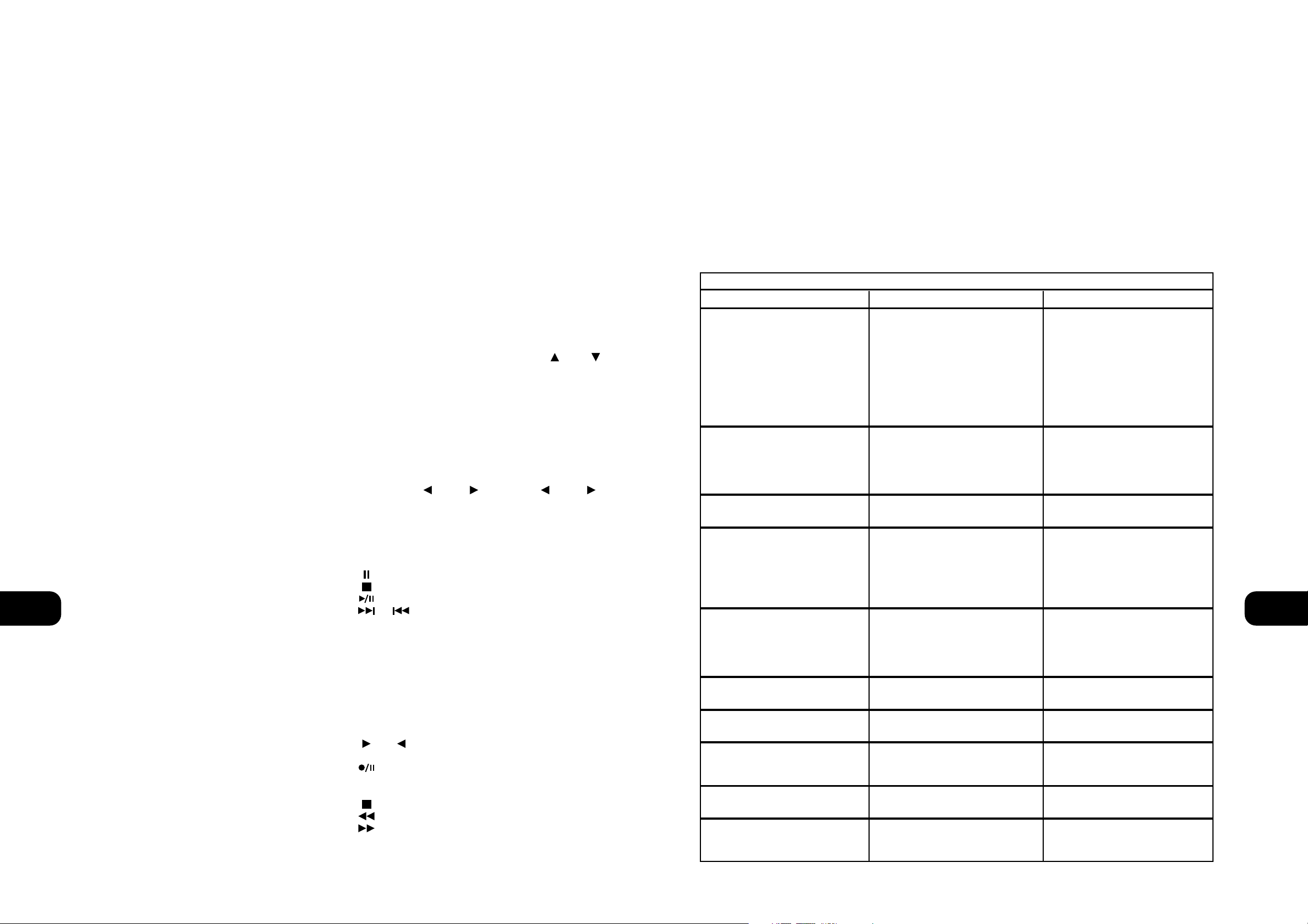
NOTES: La télécommande livrée avec le C730 est de type
universel NAD et est conçue pour commander plusieurs modèles
NAD. Certains boutons de ce combiné ne fonctionnent pas car les
fonctions concernées ne sont pas supportées par le C730. Les
boutons de sélection des entrées Vidéo 2 et Vidéo 3 (dans la
section 5), le bouton de Banque Mémoire Tuner (section 7) et les
boutons des Haut-Parleurs A et Haut-Parleurs B (section 3) du
combiné de télécommande sont sans effet dans le cas du C730.
Les rayons de soleil directs ou un éclairage d’ambiance très
lumineux peuvent avoir une incidence sur la plage et l’angle de
fonctionnement de la télécommande.
Le capteur infrarouge recevant les commandes émises à partir
d’un combiné de télécommande se trouve dans le côté gauche de
la fenêtre d’affichage. L’espace entre la télécommande et le
récepteur doit être dégagé de tout obstacle, sinon la
télécommande peut refuser de fonctionner.
F
19
ENREGISTREMENT
Toute source sélectionnée est aussi envoyée vers tout magnétophone
que vous connectez aux SORTIES MAGNETOPHONE 1 ou
MAGNETOPHONE 2 (TAPE 1 ou TAPE 2 OUTPUTS) sur le panneau
arrière. Cela vous permet d’enregistrer la source sélectionnée.
COPIER ENTRE CASSETTES (TAPE TO TAPE)
Il est possible de réaliser des copies entre deux magnétophones
connectés à votre NAD C730. Mettez la bande source sur le
magnétophone connecté à “Magnétophone 2” (Tape 2) et la
bande vierge sur le magnétophone connecté à “Magnétophone 1”
(Tape 1). En sélectionnant l’Entrée “MAGNETOPHONE 2” (TAPE
2), il est possible d’enregistrer de “Magnétophone 2” à
“Magnétophone 1”, et de contrôler le signal en provenance de la
bande d’origine.
COMBINE DE TELECOMMANDE (CF. FIGURE 4)
La Télécommande reproduit toutes les fonctions clés du NAD
C730, et comporte aussi des commandes supplémentaires
permettant de télécommander les Tuners, les Magnétophones et
les Lecteurs de CD NAD. Elle fonctionne depuis une distance
pouvant aller jusqu’à 5 mètres.
Il est conseillé d’utiliser des piles alcalines pour une longévité
maximale. Le compartiment des piles, à l’arrière de la
télécommande, est prévu pour deux piles de type (R 03) AAA.
Lors du remplacement des piles, assurez-vous de leur bonne
orientation conformément au dessin dans le fond du
compartiment des piles.
Reportez-vous aux sections précédentes du manuel pour des
descriptions détaillées des différentes fonctions.
Lors de la réception d’une commande en provenance du combiné
de télécommande, la lampe témoin “Veille/Protection” (Standby/Protection) clignote. A noter que la lampe témoin peut aussi
clignoter lors de la réception d’autres télécommandes, même si elles
ne sont pas destinées au C730 mais à d’autres modules de la chaîne.
1. BOUTON VEILLE/MARCHE
Lorsque le récepteur est sous tension (“MARCHE” (POWER)), le
fait d’appuyer sur le bouton vert Marche/Arrêt du combiné de
télécommande fait passer le NAD 730 en mode Veille et la lampe
témoin “Marche” (Power) passe à l’orange. La lampe témoin
orange indique que le NAD 730 est sous tension, mais que la
chaîne est actuellement en mode Veille. Une nouvelle impulsion
fait passer le récepteur du mode Veille au mode Marche.
2. MARCHE/ARRET ALIMENTATION
En plus de la fonction de permutation Marche/Arrêt du bouton vert
(N° 1), le NAD C730 comporte aussi un bouton Marche et Arrêt
distinct. Ceci est particulièrement utile pour maintenir la
synchronisation des appareils constituant la chaîne: De cette
manière, tous les appareils passeront en mode Veille lorsque vous
appuierez sur “Arrêt” (Off), ou passeront en mode Marche lorsque
vous appuierez sur “On” (Marche), plutôt que de se mettre en
Marche lorsque vous mettrez l’amplificateur en mode Veille.
(A noter que les autres appareils doivent eux aussi être capables de
répondre à des commandes de Marche/Arrêt distinctes).
Appuyez sur le bouton “MARCHE” (ON) pour faire passer
l’appareil du mode Veille au mode Marche; la lampe témoin de
Veille (Fig. 2, N° 2) passe de l’orange au vert et la lampe témoin
de la dernière source sélectionnée clignote puis s’allume.
Appuyez sur le bouton OFF pour mettre l’appareil en mode Veille:
la lampe témoin de Veille passe à l’orange.
3. HAUT-PARLEURS (SPEAKERS) A & B
Ces boutons n’ont aucun effet sur le C730.
4. SILENCIEUX (MUTE)
Appuyez sur le bouton “SILENCIEUX” (MUTE) (N° 4) pour
couper provisoirement le son des haut-parleurs et du casque. Le
mode Silencieux est indiqué par le clignotement du mot “MUTE”
en rouge, dans la zone d’affichage. Réappuyez sur “SILENCIEUX”
(MUTE) pour rétablir le son. La commande Mute n’affecte pas les
enregistrements faits au moyen des Sorties “Magnétophone”
(TAPE) mais agit toutefois sur le signal allant vers la “Sortie de
Préamplification” (Pre Out).
5. ENTREES
Les boutons de sélection des entrées (N° 5) ont les mêmes
fonctions que les boutons repérés de façon identique sur la face
parlante. Il y a toutefois certaines différences et quelques
fonctions supplémentaires sur le dispositif de télécommande:
Les boutons TUNER AM & FM sélectionnent l’entrée Tuner et la
bande AM ou FM, respectivement. Le récepteur s’accorde sur la
dernière station sélectionnée sur la bande AM ou FM, suivant le cas.
NOTA: Les boutons de sélection d’entrées Vidéo 2 et Vidéo 3 sont
sans effet.
6. VOLUME GLOBAL (MASTER VOLUME)
Appuyez sur les boutons MASTER VOLUME ou
(VOLUME GLOBAL) (N° 6) pour augmenter ou diminuer le
niveau sonore, respectivement. Relâchez le bouton dès que le
niveau sonore souhaité a été atteint. La Commande de Volume
motorisée sur la face parlante indiquera le niveau réglé. Les
boutons de Volume Global n’affectent pas les enregistrements faits
au moyen des Sorties “Magnétophone” (Tape) mais agissent
toutefois sur le signal allant vers la “Sortie de préamplification”
(Pre Out).
7. BOUTONS DE COMMANDE TUNER.
PREREGLAGE ou (PRESET ou )
Sélectionnent le numéro de station présélectionnée suivante ou
précédente, respectivement. Le bouton BANQUE DE MEMOIRE
(BANK) est sans effet sur le C730.
8. BOUTONS DE COMMANDE DU LECTEUR CD
(pour utilisation avec un Lecteur CD NAD).
active la fonction Pause
active l’Arrêt
active la “Lecture” (Play) ou bascule entre Lecture et Pause
ou activent le “Saut de Piste” (TRACK SKIP); appuyez
une fois sur les boutons respectifs soit pour sauter à la piste
suivante, soit pour retourner au début de la piste en cours ou
précédente.
“NEXT DISC” (Disque Suivant) Passe au disque suivant (pour
changeurs de CD NAD).
9. COMMANDE DE LA PLATINE A CASSETTES
(N° 9, pour utilisation avec une platine à magnétophone simple
(PLATINE B) ou avec une platine NAD à double magnétophone (A
et B) NAD).
ou active la “Lecture en Avant” (Forward Play) ou la
“Lecture en Arrière” (Reverse Play)
Enregistrement/Pause (Record/Pause). Appuyez pour
mettre la platine à cassettes en mode enregistrement-pause.
Appuyez sur “Lecture” (Play) pour commencer l’enregistrement.
Arrête la Lecture” ou l’Enregistrement
active le “Rembobinage Rapide” (Rewind)
active l’ “Avance Rapide” (Fast Forward).
F
18
AUCUN SON • Câble secteur débranché, ou
alimentation coupée.
• Tape 2 Monitor est sélectionné
• Fonction “Silencieux” (Mute) actif .
• Les liaisons d’amplificateur Preout/Main-in ne sont pas présentes à
l’arrière
• Les haut-parleurs ne sont pas branchés
• Vérifiez si le cordon d’alimentation est
branché et que la prise murale est
sous tension
• Désélectionnez le Mode Tape 2 Monitor.
• Désactivez la fonction “Silencieux”
(Mute).
• Assurez les liaisons
• Branchez les haut-parleurs
DEPANNAGE
PAS DE SON SUR UNE VOIE • La commande de Balance n’est pas
au centre
• Haut-parleurs incorrectement
branchés ou détériorés.
• Câble d’entrée débranché ou détérioré.
• Centrez la commande de Balance
• Vérifiez les branchements et les
haut-parleurs.
• Vérifiez les câbles et les branchements.
LA TELECOMMANDE NE FONCTIONNE PAS • Piles usées ou incorrectement insérées.
• Fenêtre d’émission ou de réception
IR obstruée.
• Le récepteur IR se trouve en plein
soleil ou sous un éclairage ’ambiance
trop puissant
• Vérifiez ou remplacer les piles.
• Retirez les obstructions.
• Eloignez l’appareil des rayons de
soleil directs, réduisez la luminosité
AUCUN SON EN MODE TUNER • Les câbles des antennes sont
mal branchés
• La station n’est pas sélectionnée ou il
y a un signal faible avec le Silencieux
FM (FM Mute) activé.
• Vérifiez les branchements de l’antenne
sur le récepteur
• Accordez à nouveau la station ou
désactivez le Silencieux FM (FM Mute)
Problème Cause Solution
GRAVES FAIBLES/IMAGE STEREO DIFFUSE • Haut-parleurs câblés en déphasé. • Vérifiez le branchement de tous les
haut-parleurs de la chaîne.
BRUIT, SIFFLEMENT SUR LES BANDES
AM ET FM
• Signal faible. • Vérifiez le réglage de la station.
Réglez ou remplacez l’antenne.
DISTORSION SUR LA BANDE FM • Signaux multivoie ou interférence
d’une autre station
• Vérifiez le réglage de la station.
Réglez ou remplacez l’antenne.
SIFFLEMENTS OU BOURDONNEMENTS
SUR LES BANDES FM ET AM
• Interférences en provenance d’autres
sources électriques - ordinateurs,
consoles de jeux.
• Vérifiez le réglage de la station.
Eteignez ou déplacez la source du
bruit électrique.
SIFFLEMENTS OU BOURDONNEMENTS
SUR LA BANDE AM
• Interférences en provenance
d’éclairages ou de moteurs électriques.
• Vérifiez le réglage de la station.
Réglez ou remplacez l’antenne AM.
AUCUNE INFORMATION RDS • Le signal de la station est trop faible
• La station n’émet pas d’informations RDS
• Vérifiez le réglage de la station.
Réglez ou remplacez l’antenne.
• Sans remède
Page 11

gummiisolierten Anschlußkabel mit den Anschlüssen “TAPE 1 IN”
(Tonbandeingang 1). Für die Aufnahme verbinden Sie den linken
und rechten Audioeingang der Bandmaschine mit den Buchsen
“TAPE OUT 1” (Tonbandausgang 1).
9. VORVERSTÄRKERAUSGANG (PRE OUT)
An den NAD C730 kann ein anderer oder zusätzlicher Endverstärker
angeschlossen werden. Wenn Sie einen externen StereoLeistungsverstärker verwenden, verbinden Sie die Buchsen PRE OUT
mit dem linken und rechten Audioeingang des Leistungsverstärkers
über ein zweifaches, gummiisoliertes Anschlußkabel.
HINWEISE: Schalten Sie den C730 und andere angeschlossene
externe Leistungsverstärker immer aus, bevor Sie Verbindungen
an den Buchsen PRE-OUT herstellen oder trennen.
Die Lautstärke- und Klangeinstellungen des NAD C730
beeinflussen das Ausgangssignal PRE-OUT.
10. SYSTEMSTEUERUNG (NAD LINK IN, OUT)
Über den NAD-LINK-Anschluß werden Befehle von und zu
anderen mit NAD-LINK-Anschlüssen ausgestatteten Geräten
übertragen. Dadurch ist die zentrale Steuerung eines ganzen
Systems und der Grundfunktionen anderer NAD-Komponenten
(Tuner, CD-Player oder Kassettendecks), die ebenfalls mit NADLink ausgestattet sind, über die Fernbedienung des Verstärkers
möglich. Für eine Funktion mit anderen Geräten verbinden Sie
den Anschluß NAD-LINK OUT am C730 mit dem Anschluß NADLINK IN eines anderen Gerätes. NAD-LINK-Anschlüsse können in
Reihe geschaltet werden, immer IN auf OUT, so daß ein ganzes
System über die Fernbedienung eines Gerätes bedient werden kann.
HINWEISE: Es wird empfohlen, NAD-Link nicht zu verbinden,
wenn Geräte mit eigenem eingebautem Fernsteuerungsempfänger
so nahe beieinander stehen, daß eine direkte Sichtverbindung zur
Fernbedienung besteht. Im Zweifelsfall versuchen Sie zuerst die
Geräte ohne NAD-Link zu steuern. Reagiert das Gerät auf die
Befehle der Fernbedienung, ist eine Verbindung von NAD-Link
nicht erforderlich.
Stellen Sie niemals eine Verbindung vom letzten Gerät zurück auf
das erste NAD-Gerät in der Kette her.
Vor dem Ein- oder Ausstecken von NAD-Link alle Geräte vom Netz trennen.
11. SOFT CLIPPING™
Die Belastung eines Verstärkers über seine nominale
Ausgangsleistung hinaus erzeugt bei lauten Passagen harte
Verzerrungen. Dies wird durch das Abschneiden oder “Hard
Clipping” der Ausgangsspitzen verursacht, für deren Wiedergabe
der Verstärker nicht ausgelegt ist. Der „Soft Clipping”-Schaltkreis
von NAD sorgt in solchen Fällen für eine weiche
Ausgangssignalbegrenzung und minimiert hörbare Verzerrungen
bei einer Übersteuerung des Verstärkers.
Wenn Sie in der Regel bei niedriger Ausgangslautstärke Musik
hören, kann der Schalter für Soft Clipping™ in Stellung AUS
(OFF) bleiben. Bevorzugen Sie jedoch eine hohe
Ausgangslautstärke mit ausgereizter Verstärkerleistung, schalten
Sie das “Soft Clipping” über diesen Schalter ein.
12. 12-V-TRIGGERAUSGANG (12 V TRIGGER OUT)
Mit diesem Ausgang können andere Geräte wie z. B. Tuner,
Leistungsverstärker usw., die ihrerseits mit einem 12-VTriggereingang ausgestattet sind, ferngesteuert werden. Dabei
kann es sich auch um eine Wechselstrom-Netzleiste mit einem 12-
V-Triggereingang handeln. Der 12-V-Triggerausgang wird
automatisch beim Einschalten des NAD C730 aus der AUS- oder
STANDBY-Stellung aktiviert.
Soll über den C730 eine externe Komponente vom Netzbetrieb in
den Bereitschaftsmodus geschaltet werden, verbinden Sie den 12V-Triggerausgang des C730 mit dem Gleichspannungseingang
dieser Komponente. Dazu wird ein 3,5-mm-StandardMiniaturstecker („Mono”) benötigt. Die Spitze ist
spannungsführend oder die “Plus”-Verbindung und der Kragen
des Eingangssteckers bildet die 12-V-Trigger- oder GroundVerbindung (“Minus”).
HINWEISE: Überprüfen Sie die Daten des 12-V-Triggereingangs
des anderen Gerätes und stellen Sie sicher, daß diese mit dem 12V-Triggerausgang des C730 kompatibel sind. NAD-Komponenten
mit einem 12-V-Triggereingang sind mit dem 12-V-Triggerausgang
des C730 voll kompatibel.
Die Spannung des 12-V-Triggerausgangs am C730 beträgt 12 V=.
Der maximale Strom darf 200 mA nicht überschreiten. Die
Stromaufnahme der 12-V-Triggereingänge von NAD ist in der
Regel niedriger als 10 mA.
Bevor Sie Verbindungen zu irgendwelchen 12-V-Triggerein-/oder ausgängen herstellen, achten Sie darauf, daß alle Geräte vom Netz
getrennt sind.
Nichtbeachten kann zu Schäden am C730 oder an mit ihm
verbundenen Geräten führen. Wenn Sie noch Fragen zu Anschluß,
Installation und Betrieb des 12-V-Triggerausgangs haben, wenden
Sie sich bitte an Ihren NAD-Händler.
13. LAUTSPRECHER (SPEAKERS)
Verbinden Sie den rechten Lautsprecher mit den Klemmen “R +”
(rechts +) und “R -” (rechts -) und achten Sie dabei darauf, daß
“R +” mit der Klemme “+” des Lautsprechers und “R -” mit der
Klemme “-” des Lautsprechers verbunden ist.
Schließen Sie den linken Lautsprecher an den Klemmen “L +”
(links +) und “L -” (links -) in der gleichen Weise an.
Verwenden Sie für den Anschluß von Lautsprechern am NAD C730
immer schwere Litzenleitungen (1,5 mm_ oder höher).
An die Schraubanschlußklemmen mit hoher Strombelastbarkeit
können Kabel mit Kabelschuhen oder Endhülsen oder Kabel mit
blanken Leitungsenden angeschlossen werden.
BLANKE DRÄHTE UND ENDHÜLSEN
Blanke Leitungsenden und Endhülsen sollten in das Stiftloch der
Anschlußbuchse eingeführt werden. Lösen Sie die
Lautsprecheranschluß-Kunststoffmutter, bis das Stiftloch freiliegt.
Führen Sie die Endhülse oder das blanke Leitungsende in das Loch ein
und sichern Sie die Leitung durch festes Anziehen der Kunststoffmutter.
Stellen Sie sicher, daß keine blanken Litzen von
Lautsprecherleitungen die Rückwand oder andere Anschlüsse
berühren. Stellen Sie sicher, daß nur ca. 1 cm blankes Kabel oder
Endhülse und keine losen Litzen vorhanden sind.
HINWEIS: Stellen Sie sicher, daß die Lautsprecher-Impedanz 4
Ohm oder mehr beträgt, wenn nur ein Lautsprecherpaar
angeschlossen wird. Achten Sie beim Anschluß von zwei
Lautsprecherpaaren unbedingt darauf, daß die Impedanz aller
Lautsprecher 8 Ohm übersteigt.
D
21
SCHNELLSTART
1. Schließen Sie die Lautsprecher an den Buchsen SPEAKERS und
die Tonquellen an den jeweiligen Eingangsbuchsen auf der
Rückwand an.
2. Stecken Sie das Netzkabel ein.
3. Drücken Sie die Taste POWER, um den NAD C730 einzuschalten.
4. Drücken Sie die erforderliche Eingangswahltaste.
5. Um Radio zu hören, schließen Sie die MW- (AM) und UKW(FM) Antenne an.
6. Drücken Sie die Taste AM/FM zur Auswahl des AM- oder
FM-Empfangs.
7. Drücken Sie die Taste PRESET/TUNE bis “PRESET” im Display
verlöscht. Der Tuner ist jetzt im Abstimmungsmodus.
8. Wählen Sie mit TUNE/PRESET oder einen Radiosender.
HINWEISE ZUR AUFSTELLUNG
Der NAD C730 sollte auf einer festen und ebenen Oberfläche
aufgestellt werden. Vermeiden Sie es, das Gerät direktem
Sonnenlicht oder Hitze und Feuchtigkeit auszusetzen.
Achten sie auf ausreichende Luftzirkulation. Stellen Sie das Gerät
nicht auf weiche Oberflächen wie z. B. Teppiche, und nicht in
abgeschlossene Bereiche wie Bücherregale oder -schränke, wenn
diese keine ausreichende Luftzirkulation gewährleisten. Schalten
Sie das Gerät aus, bevor Sie irgendwelche Verbindungen herstellen.
Zur besseren Übersicht sind die gummiisolierten
Anschlußbuchsen am NAD C730 farblich gekennzeichnet. Rot und
weiß entsprechen dem linken bzw. rechten Audiokanal, und gelb
wird für die Systemsteuerung (NAD Link) verwendet.
Verwenden Sie für den Anschluß nur hochwertige Leitungen und
Buchsen, damit der NAD C730 immer optimal und zuverlässig
arbeitet. Achten Sie außerdem darauf, daß Anschlußleitungen und
Buchsen frei von Beschädigungen sind und alle
Steckverbindungen fest sitzen.
Verwenden Sie für beste Leistung nur hochwertige
Lautprecherkabel mit mindestens 1,5 mm_ Querschnitt oder
höher. Ziehen Sie den Netzstecker aus der Steckdose, wenn das
Gerät längere Zeit nicht benutzt wird.
Sollte Wasser in den NAD C730 eindringen, schalten Sie das Gerät
aus und ziehen den Netzstecker aus der Steckdose. Lassen Sie das
Gerät von einem qualifizierten Servicetechniker untersuchen,
bevor Sie es wieder verwenden. Nehmen Sie nicht den
Gehäusedeckel ab. Im Geräteinnern befinden sich keine
vom Benutzer reparierbaren Teile. Säubern Sie das Gerät mit
einem trockenen weichen Tuch. Befeuchten Sie das Tuch bei
Bedarf leicht mit etwas Seifenwasser. Verwenden Sie keine
Lösungsmittel, die Benzol oder andere Verdunstungsmittel enthalten.
RÜCKWANDANSCHLÜSSE (Abb. 1)
1. UKW-ANTENNE (FM ANTENNA)
Die im Lieferumfang enthaltene UKW-Flachbandleitungsantenne
sollte auf der Gehäuserückseite am Anschluß FM ANTENNA (Abb.
2) über den ebenfalls mitgelieferten Symmetrieradapter
angeschlossen und auf einer senkrechten Oberfläche in Form
eines “T” angebracht werden.
Probieren Sie verschiedene Positionen der Antenne aus, um
diejenige mit der höchsten Signalstärke und den niedrigsten
Störgeräuschen zu finden. Ein mangelhaftes FM-Signal führt in der
Regel und besonders bei Stereoempfang zu einem hohen
Störgeräuschpegel und zu Störungen durch externe elektrische
Energiequellen. In Gegenden mit schlechtem UKW-Empfang kann
die Leistung des Tuners durch die Verwendung einer extern
montierten UKW-Antenne verbessert werden. In einem
Elektrofachgeschäft erhalten Sie die erforderlichen Informationen
und Dienstleistungen für eine Ihren Empfangsbedingungen
entsprechende Außenantenne.
2. MITTELWELLE-ANTENNE (AM ANTENNA)
Eine für den Mittelwelle-Empfang erforderliche AM-Ringantenne
ist im Lieferumfang des NAD C730 enthalten. Um die Antenne
anzuschließen, drücken Sie die Tasten an den
Antennenanschlußklemmen nach unten. Führen Sie die blanken
Antennendrähte in die beiden Klemmenlöcher ein und drücken
die Anschlußtasten wieder nach oben, um die Verbindung zu
sichern (siehe Abb. 2).
Probieren Sie verschiedene Antennenpositionen aus. Achten Sie
dabei auf eine senkrechte Stellung des Rings, die den
bestmöglichen Empfang bietet. Vermeiden Sie die Nähe von
großen Metallgegenständen wie Metallregale oder Ventilatoren,
da diese den Empfang stark beeinträchtigen können.
3. DISC-EINGANG (DISC INPUT)
Eingang für zusätzliche Linepegel-Signale wie CD, Mini-DiscPlayer oder Ausgangssignale von Vorverstärkern für Plattenspieler.
Verbinden Sie diesen Eingang mit dem linken und rechten
Audioausgang des Zusatzgerätes über ein zweifaches,
gummiisoliertes Anschlußkabel.
4. CD-PLAYER-EINGANG (CD INPUT)
Eingang für einen CD-Player oder eine andere LinepegelSignalquelle. Verbinden Sie diesen Eingang mit dem linken und
rechten CD-Player-Audioausgang über ein zweifaches,
gummiisoliertes Anschlußkabel. Der NAD C730 verarbeitet von
einem CD-Player nur analoge Signale.
5. VIDEOEINGANG (VIDEO INPUT)
Eingang für das Audiosignal eines Stereo-Videorekorders (oder
Stereo-TV-/Satelliten-/Kabelempfängers) oder einer anderen
Linepegel-Signalquelle. Verbinden Sie den linken und rechten
Audioausgang eines Videogerätes mit zweifachen, gummiisolierten
Anschlußkabeln mit diesen Eingängen. Hinweis: Nur Audioeingänge.
6. ZUSATZEINGANG (AUX INPUT)
Eingang für zusätzliche Linepegel-Signale wie z. B. eine zweiter
CD-Player. Verbinden Sie diesen Eingang mit dem linken und
rechten Audioausgang des Zusatzgerätes über ein zweifaches,
gummiisoliertes Anschlußkabel.
7. EIN-/AUSGANG TONBAND 2 (TAPE 2 IN, OUT)
Anschlüsse für analoge Aufzeichnung und Wiedergabe eines
beliebigen Tonbandgerätes. Verbinden Sie für die Wiedergabe den
linken und rechten Audioausgang der Bandmaschine mit einem
zweifachen, gummiisolierten Anschlußkabel mit den Anschlüssen
“TAPE 2 IN” (Tonbandeingang 2). Für die Aufnahme verbinden
Sie den linken und rechten Audioeingang der Bandmaschine mit
den Buchsen “TAPE OUT 2” (Tonbandausgang 2).
8. EIN-/AUSGANG TONBAND 1 (TAPE 1 IN, OUT)
Anschlüsse für analoge Aufzeichnung und Wiedergabe eines
beliebigen zweiten Tonbandgerätes. Verbinden Sie zur
Wiedergabe und Bandüberwachung den linken und rechten
Audioausgang der Bandmaschine mit einem zweifachen,
D
20
NAD C730 Stereo AM/FM Receiver
Page 12

6. TASTE AM/FM (MW/UKW)
Mit der Taste AM/FM wird der Tuner vom Mittelwelleband (AM) in
das UKW-Band (FM) geschaltet und umgekehrt. Im Anzeigefeld
wird die Frequenz der abgestimmten Radiostation und das
ausgewählte Frequenzband angezeigt. Die UKW-Abstimmung
erfolgt in 0,05-MHz-Schritten, die Mittelwelle-Abstimmung in 9
oder 10-kHz-Schritten, je nach Version.
7. TASTE DISPLAY
Bei Radiosendern, die RDS-Informationen übertragen, ermöglicht die
Taste DISPLAY die Umschaltung von drei verschiedenen Anzeigemodi.
Jeder Tastendruck ruft nacheinander einen der drei Modi auf:
a) Im Standardmodus wird der RDS-Name des Radiosenders
angezeigt. PS (Program Service, normalerweise der Rufname,
z. B. BBC R3)
b) Drücken Sie die Taste im Standardmodus einmal, erscheint
Radiotext (RT). Dieser kann aus dem Programmnamen, dem
Namen des Moderators, dem gerade gespielten Titel usw.
bestehen. Der Text läuft kontinuierlich in den 8
alphanumerischen Anzeigesegmenten.
c) Drücken Sie die Taste im Radiotext-Modus, wird die
Radiosendefrequenz angezeigt. Drücken Sie die Taste erneut
zur Rückkehr in den Standardmodus (a).
Bei Empfang eines Radiosenders ohne RDS:
Die Taste DISPLAY schaltet die Anzeige zwischen der
Radiosendefrequenz und dem vom Benutzer eingegebenen
Sendernamen um. Wurde kein Sendername eingegeben, wird im
Display “NO RDS” angezeigt.
Mit der Taste DISPLAY kann auch Radiosendern ohne RDS ein
Namen gegeben werden. Weitere Informationen dazu finden Sie im
Kapitel “Speichern, Abrufen und Bezeichnen von Voreinstellungen”.
8. TASTE PRESET/TUNE
(VOREINSTELLUNG/ABSTIMMUNG)
Die Taste PRESET/TUNE schaltet zwischen zwei Modi um:
a) Voreinstellungsmodus: In diesem Modus können Sie mit der
Taste PRESET/TUNE oder (Nr. 9) eine Voreinstellung
auswählen. Bei aktivem Voreinstellungsmodus wird einmal im
Display “PRESET” als Laufschrift angezeigt und die Anzeige
PRESET leuchtet im Display.
b) Abstimmungsmodus: Durch Drücken der Taste PRESET/TUNE
(Nr. 9) oder können Sie die automatische oder
manuelle Abstimmung im Frezquenzband nach oben bzw. unten
aktivieren. Bei aktivem Abstimmungsmodus wird einmal im
Display “TUNE” als Laufschrift angezeigt.
9. TASTE PRESET/TUNE UND
Die Funktion dieser Tasten ist abhängig von dem mit der
Taste PRESET/TUNE (Nr. 8) ausgewählten Einstellmodus. Im
Normalbetrieb gibt es zwei Modi:
a) Voreinstellungsmodus (im Anzeigefeld dargestellt): Drücken
Sie (tiefer) für eine niedrigere Voreinstellungsnummer
und (höher) für eine höhere. Diese Funktion arbeitet
mit “Überlauf”, d. h., wenn Sie bei der höchsten
Voreinstellungsnummer die Taste (höher) drücken, wird
wieder die niedrigste Voreinstellungsnummer (und
umgekehrt) angezeigt.
b) Abstimmungsmodus: Drücken Sie länger als eine halbe
Sekunde auf (tiefer) oder (höher) startet die
automatische Senderabstimmung nach unten bzw. oben im
Frequenzband. Der Tuner sucht automatisch nach dem ersten
einigermaßen starken Radiosender und hält dann an. Drücken
Sie zur weiteren Suche die Taste “Höher/Tiefer” erneut länger
als eine Sekunde.
Durch kurzes Tippen auf (tiefer) oder (höher) können
Sie die manuelle, präzise Abstimmung für eine bestimmte
Frequenz nach unten bzw. oben auf dem Frequenzband aktivieren.
Mit jedem Tippen auf die Tasten wird der Tuner um 0,05 MHz
nach oben oder unten im UKW-Band gesetzt. Dadurch ist eine
genaue Abstimmung auf die gewünschte Sendefrequenz möglich.
Die Abstimmung im Mittelwelleband (AM) erfolgt in 10-kHz(120-V-Version) oder 9-kHz-Schritten (230-V-Version).
Dieser Einstellmodus eignet sich sehr gut für den Empfang von
Sendern, die für eine automatische Sendersuche zu schwach sind.
Ist ein Radiosender genau abgestimmt, leuchtet “TUNED” im
Anzeigefeld auf. Die Stummschaltung kann jedoch sehr schwache
Radiosignale unterdrücken. Ein sehr schwacher Empfang eines
Stereo-Senders wird zudem durch ein starkes
Hintergrundrauschen gestört. Umschalten in den Mono-Betrieb
und Deaktivieren der Stummschaltung durch Drücken der Taste
FM MUTE/MONO (Nr. 5) verbessert den Empfang und blendet die
meisten oder sogar alle Hintergrundstörgeräusche aus.
HINWEISE: Die automatische Abstimmung funktioniert im UKW(FM) und Mittelwelleband (AM).
Selbst wenn der C730 im Abstimmungsmodus ist, wirken die
Fernbedienungstasten (PRESET UP/DOWN) nur auf die
Voreinstellungen.
Die Tasten PRESET/TUNE und werden auch in
Verbindung mit MEMORY (Nr. 4) und DISPLAY (Nr. 7) verwendet,
um anwenderdefinierte Voreinstellungen hinzuzufügen und zu
speichern. Weitere Informationen dazu finden Sie im Kapitel
“Speichern, Abrufen und Bezeichnen von Voreinstellungen”.
10. DISPLAY (ANZEIGEFELD)
Im Anzeigefeld werden alle wichtigen Receiver-Statusinformationen
angezeigt. Im Display kann abgelesen werden:
• Welcher Eingang ausgewählt ist
• Ob die Stummschaltung aktiv ist (MUTE On)
• Ob Tape Monitor aktiv ist
• Ob die Klangeinstellung deaktiviert ist (Tone Defeat On)
• Frequenzband und Frequenz des aktuellen Senders, RDS-PS
(Sendername) oder RDS-Radiotext. Letzteres nur mit RDS; mit
der Taste DISPLAY (Nr. 7) auswählen.
• Ob eine UKW-Stereosendung empfangen wird.
• Ob der UKW-Sender auch RDS ausstrahlt.
• Ob “MEMORY” aktiv ist.
• Die Voreinstellungsnummer, wenn der aktuelle Sender im
Speicher des Tuners gespeichert ist.
• Ob BLEND und FM MUTE/MODE eingeschaltet sind.
• Die Radiosignalstärke. Der Balken direkt unter “ANTENNA”
zeigt die Signalstärke des Radiosenders an. Je mehr Segmente
aufleuchten, um so stärker ist das empfangene Signal.
HINWEIS: Der Infrarotsensor für den Empfang von Signalen einer
Fernbedienung (nicht mitgeliefert) befindet sich im Anzeigefenster
links. Es muß eine klare Sichtverbindung von der Fernbedienung
zu diesem Anzeigefeldbereich bestehen. Ist diese Strecke blockiert,
funktioniert die Fernbedienung wahrscheinlich nicht.
11. LAUTSTÄRKE (VOLUME)
Mit dem Einsteller VOLUME kann die Gesamtlautstärke der an die
Lautsprecher gesendeten Signale eingestellt werden. Er wird mit
einem Motor angetrieben und ist mit der Fernbedienung
einstellbar. Der Laustärkeeinsteller (VOLUME) beeinflußt das
Tonsignal am Vorverstärkerausgang (PRE OUT), Aufnahmen über
die TAPE-Ausgänge jedoch nicht.
D
23
14. NETZKABEL (AC POWER)
Stecken Sie das Netzkabel in eine funktionstüchtige
Wechselspannungs-Steckdose ein. Stellen Sie sicher, daß vor dem
Netzanschluß alle Anschlüsse hergestellt sind.
15. GESCHALTETER NETZAUSGANG
(SWITCHED AC OUTLET)
An diesem Zusatzausgang kann das Netzkabel eines anderen
Stereogerätes eingesteckt werden. Geräte, die an diesem
Wechselspannungsausgang angeschlossen sind, werden über den
Schalter POWER auf der Frontplatte oder die Taste ON und STANDBY der Fernbedienung ein- und ausgeschaltet.
HINWEIS: Die Gesamtleistungsaufnahme aller an den
Netzausgängen angeschlossenen Geräten darf 100 Watt nicht
überschreiten.
FRONTPLATTENELEMENTE
1. NETZ EIN/AUS (POWER ON/OFF)
Drücken Sie die Taste POWER, um den Receiver einzuschalten.
Die Stand-by-Anzeige (Nr. 2) über der Drucktaste POWER leuchtet
rot auf und zur Anzeige, daß der Verstärker für den normalen
Betrieb bereit ist, kurz danach grün.
Erneutes Drücken des Schalters POWER schaltet das Gerät
vollständig AUS. Es reagiert dann nicht mehr auf die Fernbedienung.
FERNBEDIENUNG (SIEHE ABBILDUNG 4)
Taste STANDBY/ON (Nr. 1)
Wenn der Verstärker in Betrieb ist und die grüne Taste ON/OFF auf
der Fernbedienung gedrückt wird, wechselt der NAD C730 in den
Bereitschaftsmodus und die Netzanzeige leuchtet gelb. Mit einer
gelben Netzanzeige wird angezeigt, daß der Receiver zwar noch
mit Strom versorgt wird, das System aber im Bereitschaftsmodus
ist. Drücken Sie die Taste erneut, um das Gerät vom
Bereitschaftsmodus in den Betriebsmodus zu schalten.
Tasten ON und OFF (Nr. 2):
Neben der grünen Taste (Nr. 1) mit Ein-/Ausschaltfunktion hat die
Fernbedienung des NAD C730 auch die separaten Tasten ON und
OFF, mit denen Systemkomponenten besonders bequem
„sychronisiert” werden können, d. h., alle Komponenten schalten
in den Bereitschafts- oder Betriebsmodus, wenn die Taste OFF
bzw. ON gedrückt wird. So wird vermieden, daß manche Geräte
einschalten, wenn der Receiver in den Bereitschaftsmodus
geschaltet wird. (Beachten Sie, daß die anderen Komponenten
ebenfalls in der Lage sein müssen, diese Ein-/Aus-Signale zu
verarbeiten). Schalten Sie mit der Taste ON das Gerät vom
Bereitschafts- in den Betriebsmodus; das Wechseln der Stand-ByAnzeige (Abb. 2, Nr. 2) kurz danach von gelb nach grün zeigt an,
daß der Receiver betriebsbereit ist. Drücken Sie die Taste OFF, um
das Gerät in den Bereitschaftsmodus (STAND-BY) zu schalten. Die
Breitschaftsanzeige leuchtet gelb.
HINWEIS: Im Bereitschaftsmodus verbraucht der C730 nur sehr
wenig Energie. Wir empfehlen aber trotzdem, das Gerät ganz
auszuschalten, wenn es für mehrere Tage nicht benutzt wird. Das Gerät
wird durch Drücken auf die Drucktaste POWER auf der Frontplatte
(Nr. 1) ganz ausgeschaltet. Dabei verlöschen alle Leuchtanzeigen.
2. BEREITSCHAFTSMODUS-ANZEIGE
(STAND-BY-ANZEIGE)
Im normalen Betrieb leuchtet diese Anzeige grün. Im
Bereitschaftsmodus leuchtet sie gelb. Weitere Informationen dazu
finden Sie im Abschnitt 1 in diesem Kapitel.
Diese Anzeige leuchtet ebenfalls auf, wenn der Receiver einen
Befehl von der mitgelieferten Fernbedienung erhält. Wechselt der
Receiver in den Schutzmodus, blinkt die LED ununterbrochen
zweimal in der Sekunde. Dies kann bei einem Kurzschluß in der
Lautsprecherverdrahtung auftreten. Schalten Sie das Gerät
vollständig mit der Taste POWER (Nr. 1) auf der Frontplatte aus
und überprüfen Sie alle Kabel und Anschlüsse auf der Receiverund auf der Lautsprecherseite. Wenn alle Verbindungen
einwandfrei hergestellt sind, schalten Sie mit der Taste POWER
(Nr. 1) und bei niedriger Lautstärkeeinstellung wieder ein.
Besteht das Problem weiterhin, schalten Sie das Gerät aus und
wenden Sie sich an Ihren Händler.
3. TASTE BLEND (MISCHEN)
Schwache oder weit entfernte Stereo-Radiosender werden manchmal
durch das zu schwache Antennensignal mit lauten Störgeräuschen
empfangen. Wird der Tuner dann in den Monobetrieb geschaltet,
reduzieren sich zwar die Störgeräusche, aber auf Kosten des
Stereoempfangs. Mit der Blend-Funktion von NAD können Sie die
Störgeräusche reduzieren und trotzdem einen kleinen Pegel
Stereokanaltrennung behalten, anstelle eines reinen Monosignals.
Die Taste BLEND schaltet die Blend-Funktion ein oder aus. Bei
aktiver Blend-Funktion wird im Display “BLEND” angezeigt.
HINWEIS: Der Blend-Status kann für einzelne Voreinstellungen
gespeichert werden. Weitere Informationen dazu finden Sie im
Kapitel “Speichern, Abrufen und Bezeichnen von Voreinstellungen”.
4. TASTE MEMORY (SPEICHERN)
Mit der Taste MEMORY können Radiosender in den
Voreinstellungsspeicher gespeichert und anwenderdefinierte
Namen für Sender, die kein RDS senden, eingegeben werden.
Wenn im normalen Betrieb die Taste MEMORY gedrückt wird,
blinken die Voreinstellungsnummer und die rote Anzeige
“MEMORY” im Anzeigefeld. Wird innerhalb von 12 Sekunden
keine andere Taste gedrückt, kehrt der Receiver in die vorherige
Einstellung zurück. Weitere Informationen dazu finden Sie im
Kapitel “Speichern, Abrufen und Bezeichnen von Voreinstellungen”.
5. TASTE FM MUTE/MODE
(UKW-STUMMSCHALTUNG/MODUS)
In dieser Taste sind zwei Funktionen vereint: Der Receiver wird
vom Stereo- in den Mono-Betrieb geschaltet und gleichzeitig wird
die Stummschaltung deaktiviert. Der Schaltkreis für die
Stummschaltung blendet den Tuner bei einer Sendersuche oder
Abstimmung zwischen den Radiosendern aus. Auf diese Weise
wird das Rauschen beim Abstimmen vermieden.
Die Stummschaltung kann jedoch sehr schwache Radiosignale
unterdrücken. Ein sehr schwacher Empfang eines Stereo-Senders
wird zudem durch ein starkes Hintergrundrauschen gestört.
Umschalten in den Mono-Betrieb und Deaktivieren der
Stummschaltung durch Drücken der Taste FM MUTE/MODE
verbessert den Empfang und blendet die meisten oder sogar alle
Hintergrundstörgeräusche aus.
Im normalen Betrieb ist die Stummschaltung aktiviert und im
Anzeigefeld leuchtet “FM MUTE” auf. Drücken Sie die Taste FM
MUTE/MODE wenn Sie die Stummschaltung deaktivieren und vom
Stereo- in den Monoempfang schalten möchten. “FM MUTE” verlöscht
daraufhin im Anzeigefeld. Drücken Sie FM MUTE/MODE erneut, um
zum automatischen Stereo-UKW-Empfang zurückzukehren.
HINWEIS: Der Status von FM MUTE/MODE kann für einzelne
Voreinstellungen gespeichert werden. Weitere Informationen dazu
finden Sie im Kapitel “Speichern, Abrufen und Bezeichnen von
Voreinstellungen”.
D
22
Page 13

oder die gewünschte Nummer aus. Eine bestehende
Voreinstellung können Sie überschreiben. Falls die
Voreinstellungsnummer bereits belegt ist, hört “MEMORY” auf
zu blinken, aber die Voreinstellung blinkt weiterhin. Wenn Sie
die gewünschte Voreinstellung ausgewählt haben, drücken Sie
“MEMORY” erneut, um den Radiosender zu speichern.
HINWEISE: Ein neuer Radiosender kann in einen freien
Voreinstellungsplatz eingegeben oder eine bereits programmierte
Voreinstellung kann überschrieben werden. Dadurch werden alle
bisher auf diesem Voreinstellungsplatz gespeicherten Daten ersetzt.
Wenn im normalen Betrieb die Taste MEMORY gedrückt wird,
blinken die Voreinstellungsnummer und die rote Anzeige
“MEMORY” im Anzeigefeld. Wird innerhalb von 8 Sekunden keine
andere Taste gedrückt, kehrt der Tuner in die vorherige
Einstellung zurück. Die voreingestellten Radiosender werden in
einem gepufferten Speicher abgelegt. Diese Informationen bleiben
auch nach einem vollständigem Ausschalten oder Trennen des
Gerätes vom Netz für mehrere Wochen erhalten.
ABRUFEN EINER VOREINSTELLUNG
• Um einen voreingestellten Radiosender auszuwählen, überprüfen
Sie, ob der Voreinstellungsmodus aktiv ist (im Display wird
“PRESET” angezeigt). Falls nicht, drücken Sie die Taste
PRESET/TUNE (Nr. 8) und “PRESET” leuchtet im Display auf.
• Wählen Sie mit oder der Einstelltaste
“PRESET/TUNE” (Nr. 9) die Sendervoreinstellung aus, bis die
gewünschte im Anzeigefeld erscheint.
Da unbelegte Voreinstellungen übersprungen werden, müssen Sie
nicht durch leere Voreinstellungen durchblättern.
LÖSCHEN EINER GESPEICHERTEN
VOREINSTELLUNG
Ein Voreinstellungsplatz kann frei gemacht werden, indem die
darin enthaltene Information gelöscht wird:
• Wählen Sie die Voreinstellung, die gelöscht werden soll.
• Halten Sie die Tasten MEMORY (Nr. 4) und DISPLAY (Nr.7)
zwei Sekunden lang gedrückt. Die Voreinstellungsnummer und
der Text “DELETE” blinken im Display.
• Drücken Sie innerhalb von 8 Sekunden nur die Taste DISPLAY
erneut, um die Löschung dieser Voreinstellung zu bestätigen.
Für ein paar Sekunden wird der Text “DELETED” und “—” als
Voreinstellungsnummer im Display angezeigt.
BEZEICHNEN EINER VOREINSTELLUNG
Werden von einem Radiosender RDS-Informationen übertragen,
zeigt der NAD C730 automatisch die Senderkennnung an. Der
Tuner zeigt bei anderen Sendern ohne RDS oder MittelwelleSendern zwar automatisch deren Sendefrequenzen an, sie können
aber zur einfacheren Erkennung des in der Voreinstellung
gespeicherten Senders ebenfalls den Sendernamen im Klartext
eingeben: So geben Sie einen Namen ein:
1) Wählen Sie die Voreinstellung zur Bezeichnung aus.
2) Halten Sie die Taste DISPLAY (Nr. 7) zwei Sekunden lang
gedrückt. Die erste Stelle im Senderdatenbereich des
Anzeigefeldes blinkt.
3) Drücken Sie entweder oder der Einstelltaste
PRESET/TUNE (Nr. 9) zur Auswahl des ersten Zeichens (siehe
Zeichenliste unten).
4) Drücken Sie DISPLAY, um das nächste Zeichen rechts einzugeben.
5) Wählen Sie mit den Tasten PRESET/TUNE den nächsten
Buchstaben des Namens.
6) Wiederholen Sie die Schritte 3 bis 5 bis der Name oder alle
acht Stellen vollständig eingegeben sind (max. 8 Zeichen).
7) Drücken Sie die Taste MEMORY einmal, um den Vorgang
abzuschließen. Drücken Sie zur Speicherung des eingebenen
Namens die Taste MEMORY erneut.
Es sind 37 Zeichen einschließlich eines Leerzeichens verfügbar.
HINWEIS: Diese Funktion ist nur für Sender ohne RDS
einsetzbar. Bei Radiosendern mit RDS wird immer der gesendete
Name angezeigt, der auch nicht überschrieben werden kann.
AUFZEICHNEN
Das Signal jedes gewählten Eingangs wird ebenfalls direkt an eine
mit den Ausgängen “TAPE 1” oder “TAPE 2” auf der Rückwand
verbundene und aufnahmebereite Bandmaschine gesendet.
KOPIEREN VON BAND ZU BAND
Zwischen zwei Bandmaschinen, die an den NAD C730
angeschlossen sind, kann Tonmaterial kopiert werden. Legen Sie
das Quellenband in das an TAPE 2, und das leere Band in das an
TAPE 1 angeschlossene Tonbandgerät ein. Wenn Sie jetzt den
Eingang TAPE 2 wählen, können Sie von TAPE 2 auf TAPE 1
überspielen und dabei das Signal vom Originalband hören.
FERNBEDIENUNG (SIEHE ABBILDUNG 4)
Mit der Fernbedienung können alle Hauptfunktionen des NAD
C730 ausgeführt werden. Sie bietet außerdem zusätzliche externe
Steuerungsmöglichkeiten für NAD Tuner, Kassettendecks und CDPlayer. Der Betrieb ist innerhalb einer Reichweite von 5 m
möglich. Für eine maximale Betriebsdauer werden AlkalineBatterien empfohlen, die auf der Rückseite der Fernbedienung in
das Batteriefach eingelegt werden. Achten Sie beim Austausch von
Batterien darauf, daß diese entsprechend dem Schema auf dem
Batteriefachboden richtig eingesetzt werden. Eine ausführliche
Beschreibung der einzelnen Fernbedienungsfunktionen finden Sie
in vorherigen Abschnitten dieser Bedienungsanleitung.
Die Bereitschaftsmodus-/Schutzschaltungsanzeige blinkt, wenn
der Verstärker einen Befehl von der Fernbedienung erhält.
Beachten Sie, daß die LED-Anzeige nicht nur beim Empfang von
Befehlen für den C730 sondern auch bei Befehlen für andere
Systemkomponenten blinkt.
1. BEREITSCHAFTSMODUS/EIN (STANDBY/ON)
Wenn der Receiver in Betrieb ist und die grüne Taste ON/OFF auf
der Fernbedienung gedrückt wird, wechselt der NAD C730 in den
Bereitschaftsmodus und die Netzanzeige leuchtet gelb. Mit einer
gelben Netzanzeige wird angezeigt, daß der NAD C730 zwar noch
mit Strom versorgt wird, das System aber im Bereitschaftsmodus
ist. Drücken Sie die Taste erneut, um das Gerät vom
Bereitschaftsmodus in den Betriebsmodus zu schalten.
D
25
Drücken Sie die Taste MUTE auf der Fernbedienung, um die
Klangwiedergabe der Lautsprecher oder Kopfhörer kurzzeitig
abzuschalten. Der MUTE-Modus wird durch eine rote, blinkende
Anzeige von “MUTE” im Anzeigefeld signalisiert. Nochmaliges
Drücken der Taste MUTE schaltet die Klangwiedergabe wieder ein.
“MUTE” beeinflußt das Tonsignal am Vorverstärkerausgang (PRE
OUT), Aufnahmen über die TAPE-Ausgänge jedoch nicht.
12. KOPFHÖRERBUCHSE (HEADPHONE)
Musikhören über Kopfhörer ermöglicht eine 6,3-mm-StereoKlinkenbuchse, die für alle handelsübliche Kopfhörer mit beliebiger
Impedanz geeignet ist. Wenn Sie einen Kopfhörer-Stecker in diese
Buchse einstecken, werden die Lautsprecher automatisch
abgeschaltet. Lautstärke-, Klang- und Balanceeinsteller arbeiten
dann für den Kopfhörerbetrieb. Um Kopfhörer mit anderen
Anschlußsteckern wie z. B. 3,5-mm-Klinkenstecker anzuschließen,
können entsprechende Adapter verwendet werden.
13. EINGANGSWAHLTASTEN (INPUT SELECTORS)
Diese Tasten wählen den aktiven Eingang für den NAD C730 und
damit das an die Lautsprecher, die Tonbandausgänge und an den
Vorverstärkerausgang gesendete Signal. Mit Ausnahme des
Tunereingangs finden Sie dieselben Tasten auch auf der
Fernbedienung (siehe unten). Im Display wird angezeigt, welcher
Eingang gerade ausgewählt ist.
DISC Wählt die an den Buchsen “DISC” angeschlossene
Linepegel-Signalquelle als aktiven Eingang.
CD Wählt den an den Buchsen “CD” angeschlossenen CD-Player
(oder eine andere Linepegel-Signalquelle) als aktiven Eingang.
VIDEO Wählt das Signal von einem an den Buchsen “VIDEO”
angeschlossenen Videorekorder (oder Stereo-TV/Kabel/Satellitenempfänger) als aktiven Eingang.
AUX (Zusatzeingang) Wählt die an den Buchsen “AUX”
angeschlossene Linepegel-Signalquelle als aktiven Eingang.
TUNER (Radioempfänger) Wählt den Tuner als aktiven
Eingang. Der Receiver stellt die zuletzt ausgewählte Voreinstellung
oder Frequenz ein. Auf der Fernbedienung sind separate Tasten
für AM (Mittelwelle) und FM (UKW); drücken Sie eine dieser
Tasten wird der Tuner als Eingang aktiviert und der zuletzt
ausgewählte Radiosender im Mittelwelle- (AM) bzw. UKW- (FM)
Frequenzband eingestellt.
TAPE 2 (Tonband 2) Wählt “TAPE 2” als aktiven Eingang.
TAPE 1 Monitor (Hinterbandkontrolle) Wählt die
Wiedergabe einer Bandmaschine oder die Überwachung von
Aufnahmen, die gerade über den Eingang TAPE 1 gemacht
werden. Drücken Sie die Taste TAPE 1 einmal für eine Aktivierung
und ein weiteres Mal, um zur normalen Eingangseinstellung
zurückzukehren. Die Bandüberwachungsfunktion “TAPE 1”
ändert nicht die gerade aktuelle Eingangsauswahl. Ist z. B. “CD”
der aktive Eingang, wenn TAPE 1 gedrückt wird, bleibt das CDSignal aktiv und wird immer noch an die Ausgangsbuchsen “TAPE
1” und “TAPE 2” gesendet. Sie hören dann allerdings den Ton von
der an “TAPE 1” angeschlossenen Bandmaschine. Die Anzeige im
alphanumerischen Abschnitt des Anzeigefelds ändert sich bei
aktiver Bandüberwachung für 3 Sekunden in „TAPE 1”. Danach
wird wieder der aktive Eingang angezeigt. Die Anzeige „TAPE
MONITOR” im roten Feld neben der Voreinstellungsnummer im
Display bleibt so lange erhalten bis TAPE 1 wieder deaktiviert wird.
HINWEIS: Die mit dem C730 mitgelieferte NAD-UniversalFernbedienung ist für mehrere NAD-Modelle geeignet. Einige
Tasten auf dieser Fernbedienung werden vom C730 nicht
unterstützt und sind daher ohne Funktion. Die Eingangswahltasten
VIDEO 2, VIDEO 3, die Tasten TUNER BANK sowie SPEAKERS A
und SPEAKERS B auf der Fernbedienung bleiben für den C730
ohne Wirkung.
HINWEIS: Stellen Sie vor dem Anschließen oder Entfernen von
Kopfhörern sicher, daß der Lautstärkeeinsteller in Minimalstellung
(ganz entgegen dem Uhrzeigersinn) eingestellt ist. Musikhören bei
sehr hoher Lautstärke kann das Gehör schädigen.
14. EINSTELLER FÜR BASS UND HÖHEN
(BASS & TREBLE)
Der NAD C730 ist mit Klangeinstellern BASS und TREBLE
ausgestattet, um das System-Klangbild anpassen zu können.
Die mit einer Einrastung gekennzeichnete 12-Uhr-Position
bewirkt ein flaches Klangbild, ohne Verstärkung oder
Abschwächung einzelner Frequenzen. Drehen Sie den Einsteller
im Uhrzeigersinn für mehr und gegen den Uhrzeigersinn für
weniger Bässe und Höhen. Die Klangeinsteller beeinflussen das
Tonsignal am Vorverstärkerausgang (PRE OUT), Aufnahmen über
die TAPE-Ausgänge jedoch nicht.
15. KLANGEINSTELLER AUS (TONE DEFEAT)
Der Schalter TONE DEFEAT schaltet die Klangregelung des NAD
C730 aus. Wenn Sie die Klangeinsteller normalerweise sowieso in
der 12-Uhr-Position lassen, ist es ratsam, das Klangregelsystem
komplett durch Drücken der Taste TONE DEFEAT abzuschalten. In
der nichtgedrückten Stellung ist das Klangregelsystem aktiv. Wenn
Sie die Taste TONE DEFEAT hineindrücken, werden die
Klangeinsteller deaktiviert.
16. BALANCE
Der Einsteller BALANCE beeinflußt die relativen Pegel der linken
und rechten Lautsprecher. Die 12-Uhr-Position stellt die gleichen
Pegel für den linken und rechten Kanal ein. Eine Einrastung
kennzeichnet diese Position.
Drehen des Einstellers im Uhrzeigersinn verschiebt die Balance
nach rechts. Drehen des Einstellers gegen den Uhrzeigersinn
verschiebt die Balance nach links. Der Einsteller BALANCE
beeinflußt das Tonsignal am Vorverstärkerausgang (PRE OUT),
Aufnahmen über die TAPE-Ausgänge jedoch nicht.
SPEICHERN, ABRUFEN UND BEZEICHNEN
VON VOREINSTELLUNGEN
Im Speicher des C730 können bis zu 30 Voreinstellungen mit
beliebigen UKW- und Mittelwelle-Sendern gespeichert werden. Da
beim Blättern durch die Voreinstellungen leere Plätze
übersprungen werden, ist es möglich, nach der Voreinstellung Nr.
4, ohne Anzeige von Nr. 5 oder 6, direkt Nr. 7 aufzurufen.
Mit den Voreinstellungen können Sie auch speichern, ob BLEND
(Nr. 3) und FM MUTE/MODE (Nr. 5) bei jedem Abrufen der
Voreinstellung ebenfalls aktiviert werden sollen.
SPEICHERN EINER VOREINSTELLUNG
• Stellen Sie den für die Voreinstellung gewünschten
Radiosender ein (siehe Abschnitt 9 in diesem Kapitel).
Überträgt der Sender RDS-Informationen, leuchtet die RDSAnzeige auf und Kurzzeichen oder Name des Senders werden
im Anzeigefeld dargestellt. Bei Radiosendern ohne RDS wird
nur die Radiosenderfrequenz angezeigt.
• Aktivieren Sie bei Bedarf BLEND (Nr. 3) oder FM MUTE/MODE
(Nr. 5).
• Drücken Sie die Taste MEMORY (Nr. 4) zur Speicherung dieses
Senders als Voreinstellung. Die Voreinstellungsnummer und
die rote Anzeige “MEMORY” blinken im Display. Die niedrigste
verfügbare Voreinstellungsnummer wird angezeigt. Wird
innerhalb von 8 Sekunden keine andere Taste gedrückt, kehrt
der Tuner in die vorherige Einstellung zurück.
• Drücken Sie die Taste MEMORY erneut, um die Voreinstellung
zu speichern. Wenn Sie eine andere Voreinstellungsnummer
zuweisen möchten, wählen Sie mit der Taste PRESET/TUNE
D
24
LEERZEICHEN
A B C D E F G H I
J K L M N O P Q R S
T U V W X Y Z 0 1 2
3 4 5 6 7 8 9
Page 14

D
27
2. NETZ EIN/AUS (POWER ON/OFF)
Neben der grünen Taste (Nr. 1) mit Ein-/Ausschaltfunktion hat die
Fernbedienung des NAD C730 auch die separaten Tasten ON und
OFF, mit denen Systemkomponenten besonders bequem
„sychronisiert” werden können, d. h., alle Komponenten schalten in
den Bereitschafts- oder Betriebsmodus, wenn die Taste OFF bzw. ON
gedrückt wird. So wird vermieden, daß manche Geräte einschalten,
wenn der Receiver in den Bereitschaftsmodus geschaltet wird.
(Beachten Sie, daß die anderen Komponenten ebenfalls in der Lage
sein müssen, diese Ein-/Aus-Signale zu verarbeiten).
Schalten Sie mit der Taste ON das Gerät vom Bereitschafts- in den
Betriebsmodus; die Stand-By-Anzeige (Abb. 2, Nr. 2) wechselt
kurz danach von gelb nach grün, und die Anzeige für die zuletzt
gewählte Tonquelle leuchtet auf. Drücken Sie die Taste OFF, um
das Gerät in den Bereitschaftsmodus (STAND-BY) zu schalten. Die
Breitschaftsanzeige leuchtet gelb.
3. LAUTSPRECHER A, B (SPEAKERS A, B)
Diese Tasten haben für den C730 keine Wirkung.
4. MUTE (STUMMSCHALTUNG)
Drücken Sie die Taste „MUTE” (Nr. 4), um die Klangwiedergabe
der Lautsprecher oder Kopfhörer kurzzeitig abzuschalten. Der
MUTE-Modus wird durch eine rote, blinkende Anzeige von
“MUTE” im Anzeigefeld signalisiert. Nochmaliges Drücken der
Taste MUTE schaltet die Klangwiedergabe wieder ein. “MUTE”
beeinflußt das Tonsignal am Vorverstärkerausgang (PRE OUT),
Aufnahmen über die TAPE-Ausgänge jedoch nicht.
5. EINGÄNGE (INPUTS)
Die Eingangswahltasten (Nr. 5) erfüllen dieselben Funktionen wie
die gleichnamigen Tasten auf der Geräte-Frontplatte. In manchen
Bereichen unterscheidet sich die Fernbedienung jedoch und
bietet zusätzliche Funktionen:
Die Tasten TUNER AM & FM aktivieren den Tunereingang und das
AM- bzw. FM-Frequenzband. Der Receiver stellt den zuletzt
ausgewählten Mittelwelle- oder UKW-Sender ein.
HINWEIS: Die Eingangswahltasten VIDEO 2 und VIDEO 3 haben
keine Wirkung.
6. LAUTSTÄRKE (MASTER VOLUME)
Drücken Sie die Tasten MASTER VOLUME oder (Nr. 7),
um die Lautstärke zu erhöhen bzw. zu verringern. Lassen Sie die
Taste los, wenn die gewünschte Lautstärke erreicht ist. Der
motorgesteuerte Lautstärkeeinsteller auf der Frontplatte bewegt
sich entsprechend der eingestellten Lautstärke. Die Tasten
MASTER VOLUME beeinflussen das Tonsignal am
Vorverstärkerausgang (PRE OUT), Aufnahmen über die TAPEAusgänge jedoch nicht.
7. TUNEREINSTELLUNG (TUNER CONTROL)
PRESET oder wählt eine niedrigere bzw. höhere
Voreinstellungsnummer. Die Taste BANK hat für den C730 keine Wirkung.
8. TASTEN CD PLAYER CONTROL
(FÜR NAD CD-PLAYER)
aktiviert Pause
aktiviert Stop
aktiviert Wiedergabe oder schaltet zwischen Wiedergabe und
Pause um
oder aktiviert Titelspringen. Einmal drücken, um auf
den nächsten Titel bzw. auf den Anfang des aktuellen oder
vorherigen Titels zu springen.
“NEXT DISC” wählt nächste CD (für NAD CD-Wechsler).
9. TASTEN CASSETTE DECK CONTROL
(für einfache (DECK B) oder doppelte (A und B) NAD
Kassettendecks).
oder aktiviert Vorwärts- oder Rückwärtswiedergabe.
Aufnahme/Pause. Drücken für Aufnahmepause. Wiedergabe
drücken für Aufnahmebeginn.
stoppt Wiedergabe oder Aufnahme.
aktiviert Zurückspulen.
aktiviert schnellen Vorlauf.
HINWEISE: Die mit dem C730 mitgelieferte NAD-UniversalFernbedienung ist für mehrere NAD-Modelle geeignet. Einige
Tasten auf dieser Fernbedienung werden vom C730 nicht
unterstützt und sind daher ohne Funktion. Die Eingangswahltasten
VIDEO 2, VIDEO 3 (in Abschnitt 5), die Tasten TUNER BANK
(Abschnitt 7) sowie SPEAKERS A und SPEAKERS B (Abschnitt 3)
auf der Fernbedienung bleiben für den C730 ohne Wirkung.
Direkte Sonneneinstrahlung oder sehr helle
Umgebungsbeleuchtung kann den Wirkungsbereich und
Strahlungswinkel der Fernbedienung beeinträchtigen.
Der Infrarotsensor in der linken Ecke des Anzeigefeldes empfängt
die Befehle von der Fernbedienung. Es muß eine klare
Sichtverbindung von der Fernbedienung zu diesem
Anzeigefeldbereich bestehen. Ist diese Strecke blockiert,
funktioniert die Fernbedienung wahrscheinlich nicht.
D
26
PROBLEMLÖSUNG
KEIN TON • Netzkabel ausgesteckt oder
Netzschalter nicht “ON”
• “Tape 2 Monitor” ausgewählt
• “MUTE” aktiv
• Hintere Pre-Out/Main-In
Verstärkerverbindungen fehlen
• Lautsprecher nicht aktiviert
• Netzkabel und Netzschalter
überprüfen
• “Tape 2 Monitor” deaktivieren
• “MUTE” deaktivieren
• Verbindungen herstellen
• Lautsprecher A oder B aktivieren
EIN KANAL OHNE TON • Balanceeinsteller nicht in Mittelstellung
• Lautsprecher nicht richtig
angeschlossen oder defekt.
• Eingangsanschlußleitung ausgesteckt
oder defekt
• Balanceeinsteller in Mittelstellung
bringen
• Lautsprecher und Anschlüsse
überprüfen
• Anschlußleitungen und Verbindungen
überprüfen
FERNBEDIENUNG FUNKTIONIERT NICHT • Batterien leer oder falsch eingelegt
• IR-Sender- oder Empfängerfenster
verdeckt
• IR-Empfänger in direktem Sonnenlicht
oder sehr hohe Umgebungsbeleuchtung
• Batterien überprüfen oder ersetzen
• Hindernis beseitigen
• Gerät nicht in direktem Sonnenlicht
aufstellen, Umgebungsbeleuchtung
reduzieren
KEIN TON BEI RADIOEMPFANG • Antennenanschlüsse falsch eingesteckt
• Kein Sender ausgewählt oder sehr
schwaches Signal mit aktiviertem
FM MUTE.
•
Antennenanschluß am Receiver
überprüfen
• Sender nachstellen oder FM MUTE
deaktivieren
Problem Ursache Abhilfe
SCHWACHE BÄSSE/UNDEUTLICHES
STEREOKLANGBILD
• Lautsprecheranschlüsse verpolt • Alle Lautsprecheranschlüsse im
System überprüfen
RAUSCHEN UND STÖRUNGEN BEI
AM- UND FM-EMPFANG
• Schwaches Signal • Senderabstimmung überprüfen.
Antenne einstellen oder ersetzen
VERZERRUNGEN BEI FM-EMPFANG • Überlagerungen oder Streuungen von
anderen Sendern
• Senderabstimmung überprüfen.
Antenne einstellen oder ersetzen
Mittelwelle (AM)- und UKW (FM)
Empfang mit pfeifenden und
brummenden Geräuschen
• Störungen durch andere elektrische
Verbraucher – Computer,
Spielekonsolen
• Senderabstimmung überprüfen.
Störendes elektrisches Gerät
ausschalten oder Abstand vergrößern
Mittelwelle (AM)-Empfang mit pfeifenden
und brummenden Geräuschen
• Störungen durch fluoreszierende
Beleuchtung oder Elektromotore
• Senderabstimmung überprüfen.
Mittelwelle-Antenne einstellen
oder ersetzen
KEINE RDS-INFORMATION • Sendersignal zu schwach
• Sender überträgt keine RDS-Daten
• Senderabstimmung überprüfen.
Antenne einstellen oder ersetzen
• Keine Abhilfe
Page 15

para conectar la entrada “Audio Input” izquierda y derecha del
amplificador de potencia a las tomas PRE OUT 1
NOTAS: Ponga siempre en off eñ C730 y los amplificadores de
potencia externos asociados antes de conectar o desconectar
cualquier cosaa las tomas PRE-OUT.
La señal de salida Pre-Out quedará afectada por los ajustes de
control de volumen y tono del NAD C730.
10. NAD LINK IN, OUT
(ENTRADA, SALIDA DE CONEXIÓN NAD)
El conector NAD-Link se usa para transmitir órdenes de otros
equipos que tengan conectores NAD-Link. Esto permite control
central de un sistema completo, y también algunas de las
funciones básicas de otros componentes NAD (como tocadiscos
CD o tocacassettes) también equipados con NAD-Link que se
controlan con el control remoto del receptor. Para funcionar con
tales otros equipos, conecte la salida “NAD-Link” del C730 con la
entrada “NAD-Link” del otro equipo. Los conectores NAD-Link se
pueden encadenar en margarita, IN con OUT, de modo que un
sistema completo puede controlarse desde los dispositivos de
control remoto de un solo equipo.
NOTAS: Es aconsejable no conectar NAD-Link si estos equipos
tienen incorporado su propio receptor de órdenes de control
remoto y están colocados juntos, directamente a la vista del
equipo manual de control remoto. Si usted no está seguro, intente
hacer funcionar los productos primero sin NAD-Link, si el equipo
responde a la orden del control remoto, no será necesario
conectar NAD-Link.
No conecte jamás el último equipo otra vez al primer equipo NAD
de la cadena NAD-Link. Desenchufe todos los equipos de la red
antes de conectar o desconectar NAD-Link.
11. SOFT CLIPPING™ (RECORTE BLANDO)
Cuando un amplificador se excita más allá de la salida de potencia
especificada, puede oírse un sonido duro y distorsionado en los
volúmenes muy altos. Esto se debe a que el amplificador corta o ‘hace
recorte duro’ de los picos máximos de sonido para cuya
reproducción no ha sido diseñado. El circuito NAD Soft Clipping(tm)
(recorte suave) limita suavemente la salida del sistema para
minimizar la distorsión audible si el amplificador es sobreexcitado.
Si usted al escuchar utiliza niveles de potencia moderados puede
dejar el interruptor Soft Clipping™ en Off. Si es probable que
escuche usted altos niveles, que pudieran forzar la capacidad de
potencia del amplificador, ponga el interruptor Soft Clipping en
On (conectado).
12. 12V TRIGGER OUT
(SALIDA DE DISPARADOR DE 12V)
Esta salida permite conectar o desconectar remotamente el
equipo auxiliar tal como un sintonizador, amplificador de
potencia, etc. que estén también equipados con una entrada de
disparador de 12V. Esto puede ser también una banda de
alimentación de toma de CA equipada con una entrada de
disparador de 12V. La salida de disparador de 12V se activa
siempre que el equipo esté activado y conmutado para modo
normal de funcionamiento a partir de Stand-by u Off.
Para poner un componente externo en Stand.by/Power On a
través del C730, conecte la salida de disparador de 12V del C730
con el enchufe jack de entrada CC del componente remoto. El
enchufe necesario es un enchufe Mini-Jack standard de 3,5 mm
(“mono”). La punta es la conexión con corriente o +, el fuste del
jack de entrada es la conexión de disparador de 12V - o de tierra.
NOTAS: Compruebe las especificaciones del terminal de entrada
Trigger de los otros componentes para asegurar que sean compatibles
con la salida de disparador de 12V del C730. Los componentes NAD
equipados con disparadores de entrada de 12V son totalmente
compatibles con el disparador de salida de 12V del C730.
El voltaje de salida del disparador de 12V del C730 es de 12V CC.
La corriente máxima total no ha de excederse de 200mA.
Típicamente, los disparadores de entrada NAD de 12V toman
menos de 10mA de corriente. Antes de hacer cualesquiera
conexiones con cualquier entrada o salida de disparador de 12V,
asegúrese de que todos los componentes estén desconectados de
la red de CA.
Si no se hace lo anterior puede producirse daño al C730 o
cualquier componente auxiliar unido al mismo. Si tiene alguna
duda sobre las conexiones, instalación y funcionamiento de la
salida de disparador de 12 V consulte a su concesionario NAD.
13. SPEAKERS (ALTAVOCES)
Conecte el altavoz derecho a los terminales marcados con ‘R +’ y
‘R -’ asegurando que el ‘R+’ esté conectado al terminal ‘+’ de su
altavoz y el ‘R-’ está conectado al terminal ‘-’ del altavoz.
Conecte los terminales marcados con ‘L+’ y ‘L-’ al altavoz
izquierdo de la misma manera.
Use siempre cable de trenzado para trabajos pesados (calibre 16;
1,5mm, o más grueso) para conectar los altavoces a su NAD C730.
Pueden usarse los terminales de poste de doblado de alta corriente
como terminal de corriente para cables que terminen en tomas de
horquilla o pasador o para cables con extremos de hilo desnudo.
CONECTORES DE CABLE DE HILO DESNUDO Y
DE PASADOR
Los cables de hilo desnudo y tomas de pasador han de insertarse en
el orificio de fuste del terminal. Desenrosque el casquillo de plástico
del terminal del altavoz hasta que quede expuesto el orificio de fuste
del tornillo. Inserte el pasador o extremo de cable desnudo en
orificio y sujete el cable apretando el casquillo del terminal.
Asegure que el hilo desnudo de los cables de altavoz no toque el panel
trasero ni otra toma. Asegure que haya únicamente 1 cm de cable
desnudo o pasador y no haya torones sueltos del hilo de los altavoces.
NOTA: Asegúrese de que la impedancia de altavoz sea de 4
ohmios o más al conectar sólo un par de altavoces; asegúrese de
que la impedancia de altavoz de todos los altavoces sea de más de
8 ohmios al conectar dos conjunto de altavoces.
14. CORDON DE LINEA DE CA
Enchufe el cordón de línea de CA a una toma de pared de CA con
corriente. Asegure que todas las conexiones se hayan hecho antes
de conectar con la alimentación eléctrica de la red.
15. SWITCHED AC OUTLET
(TOMA DE CA CONMUTADA)
El cordón de alimentación eléctrica de CA de otro componente
puede enchufarse en esta salida de accesorio. Los componentes
enchufados a esta salida se pondrán en On y Off con el pulsador
POWER del panel delantero o con el pulsador ON y STAND-BY del
equipo manual de control remoto.
NOTA: El consumo eléctrico total de cualesquiera componentes
conectados a las salidas de CA no puede sobrepasar los 100 Vatios.
E
29
INICIO RAPIDO
1. Conecte los altavoces a los terminales de Speaker y las fuentes
de sonido a las correspondientes tomas en la parte trasera.
2. Enchufe el cordón de alimentación de CA.
3. Pulse el pulsador POWER para poner en On el NAD C 730.
4. Pulse el selector de entrada requerido.
5. Para escuchar radio, conecte la antena de AM y FM.
6. Pulse el pulsador AM/FM para seleccionarrecepción de AM o FM.
7. Pulse el pulsador “Preset/Tune” de modo que no se encienda
PRESET en el visualizador, el sintonizador está ahora en modo
Tune (sintonización).
8. Use Preset/Tune o para seleccionar una estación.
NOTAS SOBRE LA INSTALACION
Su NAD C730 debe colocarse sobre una superficie firme y nivelada.
Evite colocar el equipo a la luz directa del sol o cerca de calor o
humedad. Deje una ventilación adecuada. No coloque el equipo
sobre una superficie blanda como una alfombra. No lo coloque en
un área cerrada, como una estantería o armario, que impida el
paso del aire por las ranuras de ventilación. Asegure que el equipo
esté desconectado antes de hacer cualquier conexión.
Los enchufes RCA de su NAD C730 tienen código de colores para
mayor comodidad. El rojo y el blanco son audio de Derecha e
Izquierda respectivamente, y el amarillo es para la NAD Link
(conexión NAD). Use conductores y tomas de alta calidad para
rendimiento y fiabilidad óptimos. Asegure que los conductores y
tomas de enchufe no estén dañados en modo alguno y que las
tomas de enchufe estén enchufadas firmemente hasta el fondo.
Para mejor rendimiento, use conductores de altavoz de calidad de
calibre 16 (1,5 mm) de espesor o más. Si el equipo no va a usarse
durante algún tiempo, desconecte el enchufe de la toma de CA.
Si penetra agua en su NAD C730, corte la alimentación eléctrica
del equipo y quite el enchufe de la toma de CA. Haga que
inspeccione el equipo un técnico de servicio cualificado antes
intentar usarlo otra vez. No quite la cubierta, no hay piezas
en el interior que puedan ser objeto de servicio por el
usuario. Use un paño suave y seco para limpiar el equipo. Si es
necesario, humedezca un poco el paño con agua jabonosa. No
use soluciones que contengan benzol ni otros agentes volátiles.
CONEXIONES DEL PANEL TRASERO (fig 1)
1. ANTENA FM
Se incluye una antena de FM de cable de cinta y debe conectarse
al conector FM en la parte trasera del equipo usando el adaptador
“balun” (vea fig 2). La antena de cinta debe montarse sobre una
superficie vertical y colocarse de modo que forme una “T”.
Experimente con la colocación de la antena para encontrar la
posición que dé la mejor fuerza de señal y el ruido de fondo más
bajo. Una señal FM inadecuada normalmente produce altos
niveles de susurro, especialmente en estéreo, e interferencia de
fuentes eléctricas externas. En áreas de recepción FM defectuosa,
el rendimiento de la sección del sintonizador puede mejorarse
usando una antena FM montada externamente. Un instalador de
antenas cualificado podrá asesorar y montar una antena
recomendada para las condiciones de recepción de usted.
2. ANTENA AM
Se suministra una antena AM de bucle con el NAD C730 y se
necesita para la recepción AM. Para conectar la antena AM,
primero pulse las teclas de los terminales “Antenna” abajo.
Inserte los cables desnudos de antena en los dos orificios de
terminales y pulse las teclas de conector arriba otra vez para
asegurar la conexión (vea fig 2).
Pruebe varias posiciones para la antena pero asegure siempre que el
bucle esté colocado verticalmente para mejor recepción. Si se coloca
la antena próxima a artículos metálicos grandes como estanterías
metálicas o radiadores esto puede interferir con la recepción.
3. DISC INPUT (ENTRADA DE DISCO)
Entrada para señales de entrada de nivel de línea adicional como
CD, tocadiscos Mini Disc o la señal de salida de un amplificador
de realce para un tocadiscos. Use un conductor doble RCA-a-RCA
para conectar las ‘Salidas de Audio’ de derecha e izquierda de los
equipos auxiliares a esta entrada.
4. CD INPUT (ENTRADA DE CD)
Entrada para una fuente de señal de CD u otra señal de nivel de
línea. Use un conductor doble RCA-a-RCA para conectar las
‘Audio Output’ de izquierda y derecha del tocadiscos de CD a esta
entrada. El NAD C730 acepta únicamente señales analógicas de su
tocadiscos de CD.
5. VIDEO INPUT (ENTRADA DE VÍDEO)
Entrada para la señal de audio procedente de una cámara de
grabación de vídeo VCR (o receptor estéreo de TV/Satélite/Cable)
u otra fuente de audio de nivel de línea. Usando conductores
dobles RCA-a-RCA, conecte la ‘Salida de Audio’ de izquierda y
derecha del equipo a estas entradas. Nota: Estas son entradas de
audio únicamente.
6. AUX INPUT (ENTRADA AUXILIAR)
Entrada para señales de entrada de nivel de línea adicional como
otro tocadiscos CD. Use un conductor doble RCA-a-RCA para
conectar las ‘Salidas de Audio’ de derecha e izquierda de los
equipos auxiliares a esta entrada.
7. TAPE 2 IN, OUT
(ENTRADA, SALIDA DE CINTA 2)
Conexiones para grabación y escucha analógicas para una
grabadora de cinta de audio de cualquier tipo. Usando conductores
dobles RCA-a-RCA conecte la ‘Salida de Audio’ de izquierda y
derecha de la máquina de cintas a las tomas TAPE 2 IN para
escuchar. Conecte la ‘Entrada de Audio’ de izquierda y derecha de
la máquina de cintas a las tomas TAPE 2 OUT para grabar.
8. TAPE 1 IN, OUT
(ENTRADA, SALIDA DE CINTA 1)
Conexiones para grabación y escucha analógicas para una
grabadora de cinta de audio secundaria de cualquier tipo. Usando
conductores dobles RCA-a-RCA, conecte la ‘Salida de Audio’ de
izquierda y derecha de la máquina de cintas a las tomas TAPE 1
IN para escucha y control de cintas. Conecte la ‘Entrada de Audio’
de izquierda y derecha de la máquina de cintas a las tomas TAPE
1 OUT para grabar.
9. PRE OUT (SALIDA PRE)
El NAD C730 permite la conexión de un amplificador de potencia
diferente o adicional. Si está usted usando un amplificador de
potencia externo estéreo, use un conductor doble RCA-a-RCA
E
28
Receptor Estereo de AM/FM NAD C730
Page 16

7. VISUALIZADOR
Con estaciones que tienen información RDS, el pulsador Display
(visualizador) repasa tres modos diferentes de visualización, con cada
pulsación sucesiva del pulsador se activa el siguiente de los tres modos:
a) En modo de por defecto, se visualiza el nombre RDS de la estación,
el Program Service (servicio de programa) (PS; normalmente las
letras de llamada de estación, BBC R3, por ejemplo).
b) A partir del modo de por defecto, pulse el pulsador una vez para
visionar Radio Text (RT) (texto de radio). Este puede ser
información adicional como el nombre del presentador o del
programa; la canción que se escucha, etc. Este texto se repasa
continuamente en los 8 segmentos del visualizador alfanumérico.
c) Pulse el pulsador a partir del modo de visualización RT para
visualizar la frecuencia de la estación. Púlselo otra vez para
volver al modo de por defecto (a).
Cuando se sintoniza una estación no RDS
El pulsador Display alterna la visualización mostrando la
frecuencia de la estación o el nombre de la estación introducido
por el usuario. Si el usuario no introdujo nombre el visualizador
indica “NO RDS”.
También se usa el pulsador Display para etiquetar estaciones no
RDS con un nombre. Vea el capítulo separado “Memorización,
Reactivación y Etiquetado de Presets” para más información.
8. PRESET/TUNE (PREAJUSTE/SINTONIZACIÓN)
El pulsador “Preset/Tune” (preajuste/sintonización) alterna entre
dos modos diferentes:
a) Modo Preset: En este modo usted puede usar los pulsadores
Preset/Tune o (No. 9) para seleccionar un Preset.
Seleccionado Preset Mode, PRESET repasa una vez el
visualizador y se enciende el indicador PRESET en el visualizador.
b) Modo sintonización Pulsando el pulsador Preset/Tune (No. 9)
o puede usted activar sintonización automática o
manual respectivamente abajo o arriba de la banda de
frecuencia. Seleccionado modo Tune, TUNE repasa todo el
visualizador una vez.
9. PRESET/TUNE Y
La función de estos pulsadores depende del modo de sintonización
que se seleccione con el pulsador Preset/Tune (No. 8). El pulsador
Preset/Tune alterna entre los dos modos de funcionamiento:
a) Modo Preset (indicado en el área del visualizador): Pulse el
pulsador (abajo) para pasar a un número inferior de
Preset; pulse el pulsador (arriba) para pasar a un
número superior de Preset. Esta es una función de “envuelta”,
de modo que si se va a partir del número superior de Preset,
el sintonizador va al número inferior de Preset o viceversa
cuando se sintoniza hacia arriba o hacia abajo.
b) Modo sintonización Pulse el pulsador (abajo) o el
pulsador (arriba) durante más de 1 segundo para activar
sintonización automática respectivamente arriba o abajo de la
banda de frecuencia. El sintonizador busca automáticamente
la primera estación de radio razonablemente fuerte, y allí se
para. Pulse otra vez el pulsador “Down/Up” (abajo/arriba)
durante 1 segundo para comenzar a buscar otra vez.
Pulsando brevemente los pulsadores (abajo) o
(arriba) usted puede activar sintonización manual
respectivamente hacia arriba o hacia abajo de la banda de
frecuencia para sintonización exacta con una frecuencia
específica. Con cada breve pulsación, el sintonizador da pasos de
0.05 MHz en FM con lo que usted puede sintonizar exactamente
la frecuencia deseada. Para AM los pasos de sintonización están
ajustados a 10 kHz (versión de 120V) o 9 kHz (versión de 230V).
Este modo de sintonización también puede ser útil cuando se
intenta recibir una estación de radio, que es demasiado débil para
el modo de búsqueda automática. Cuando se sintoniza
exactamente una estación, se enciende TUNED (sintonizada)
arriba en el visualizador. No obstante, los circuitos de
silenciamiento pueden suprimir las señales de estación de radio
muy débiles. Si tal debilísima estación está en estéreo tendrá un
alto nivel de susurro de fondo. Cambiando a Mono Mode y
desactivando los circuitos de silenciamiento pulsando el pulsador
FM MUTE/MODE (No. 5) se permite escuchar la estación y se
cancela gran parte o la totalidad de este ruido de fondo.
NOTAS: Se dispone de sintonización automática tanto en FM
como en AM.
Aunque el C730 esté en Tune Mode, estos pulsadores Preset Up y
Down del control remoto únicamente cambian presets.
Los pulsadores “Preset/Tune” y se usan también con
los pulsadores “Memory” (No. 4) y “Display” (No. 7) para añadir
y memorizar nombres definidos por el usuario para Presets. Vea
el capítulo separado “Memorización, Reactivación y Etiquetado
de Presets” para más información.
10. AREA DE VISUALIZACION
El área de visualización da toda la información vital sobre el
estado del receptor. Se visualizan:
• qué entrada està seleccionada
• Volume MUTE On (SILENCIAMIENTO Volumen On)
• Tape Monitor engaged (Monitor de Cinta activado)
• Tone Defeat On (Anulación de Tono On)
• Banda y frecuencia de la estación actual, RDS PS (nombre de
la estación), o Texto de Radio RDS. Las dos últimas cosas
únicamente si se dispone de RDS; seleccione usando el
pulsador Display (No. 7).
• Si se recibe una retransmisión FM Stereo.
• Si la estación FM retransmite también RDS.
• Si se ha activado “Memory”.
• El número de Preset si la estación actual está memorizada en
la bancada de memoria del sintonizador.
• Si se han puesto en “On” “Blend” y “FM Mute/Mode”.
• Fuerza de Señal de Radio. Las barras justo debajo de
“ANTENNA” indican la fuerza de señal de la estación de radio.
Cuanto más barras se enciendan, más fuerte es la estación.
NOTA: El sensor de infrarrojos, que recibe órdenes del control
remoto (no se suministra), está situado al lado derecho de la
ventanilla de visualizador. Debe haber un paso libre de obstáculos
de línea de mira desde el control remoto a esta ventanilla; si tal
paso está obstruido, el control remoto puede que no funcione.
11. VOLUME (VOLUMEN)
El control VOLUME ajusta el nivel general de las señales que se
alimentan a los altavoces. Es accionado por motor y se puede
ajustar desde el equipo manual de control remoto.. El control
VOLUME no afecta a las grabaciones hechas usando las salidas
Tape pero afecta a las señales que van a la salida Pre-amp
(preamplificador) (Pre-Out).
En el equipo manual de control remoto, pulse el pulsador MUTE
para poner temporalmente en off el sonido que va a los altavoces
y auriculares. El modo Mute se indica con la plabra “MUTE” que
centellea en el área de visualización. Pulse otra vez MUTE para
restablecer el sonido. Mute no afecta a las grabaciones hechas
usando las salidas Tape pero afecta a la señal que va a la salida
Pre-amp (Pre Out).
E
31
CONTROLES DEL PANEL DELANTERO.
1. POWER ON/OFF (ALIMENTACIÓN
ELÉCTRICA CONECTADA/DESCONECTADA)
Pulse el pulsador POWER para poner el amplificador en On. Se
enciende con color ámbar el indicador Power (No. 2) encima del
pulsador de alimentación eléctrica y transcurrida una corta pausa
se pone con color verde para indicar que ahora el receptor está
dispuesto para funcionamiento normal.
Si se pulsa el interruptor POWER otra vez se pone el equipo
totalmente en OFF, no responderá al control remoto.
CONTROL REMOTO (VEA LA FIGURA 4)
Pulsador STANDBY/ON (No. 1)
Cuando el receptor está puesto en On, si se pulsa el pulsador
verde de On/Off en el equipo manual de control remoto el NAD
C730 se pone en modo Stand-by y el indicador Power se pone de
color ámbar. El indicador Power ambar muestra que se alimenta
energía pero actualmente el sistema está en reserva en Modo
Standby. Pulse otra vez para poner el receptor en On a partir del
modo Stand-by.
Pulsador ON y OFF (No. 2):
A parte de la función alternativa de On/Off del pulsador verde (No.
1), el control remoto del NAD C730 tiene también un pulsador
separado de On y Off. Este puede ser particularmente útil para
mantener los componentes dentro de un sistema “in-sync”
(sincronizados). De esta manera todos los componentes se ponen
en Stand-by cuando se pulsa Off en el interruptor para modo de
funcionamiento cuando se pulsa On, en lugar de que algunos
componentes se pongan en On cuando el receptor se pone en
Stand-by. (Observe que los demás componentes han de ser
capaces de responder también a las órdenes separadas de On y
Off). Pulse el pulsador ON para cambiar el equipo de Stand-by a
modo de funcionamiento; El indicador Stand-by (Fig. 2; No. 2)
cambia de ambar a verde para indicar que el receptor está
preparado para uso. Pulse el pulsador OFF para poner el equipo
en modo Stand-by. El indicador de Stand-by se enciende con color
ámbar.
NOTA: En el modo Stand-by el C730 usa muy poca corriente
eléctrica. No obstante, recomendamos que desconecte totalmente
el equipo si no lo va a usar durante más de un par de días.
Desconecte completamente pulsando el pulsador POWER del
panel delantero (No. 1), se apagarán todas las luces.
2. STAND-BY INDICATOR
Este indicador se enciende con color verde durante el
funcionamiento normal. En modo Stand-by ek indicador se enciende
con color ambar. Vea la seccion 1 de este capítulo para más
información. El indicador centellea cuando el receptor recibe una
orden del control remoto desde el equipo manual que se suministra.
Si el receptor se pone en modo “protection” el diodo Led
centellea continuamente a dos centelleos por segundo. Esto
puede ocurrir si hay un cortocircuito en el cableado de altavoces.
Ponga el equipo totalmente en off usando el pulsador Power del
panel delantero (No 1) y compruebe todos los cables y
conexiones tanto en el equipo como en los altavoces.
Restablecidas correctamente todas las conexiones, ponga el
pulsador Power (No 1) en on, inicialmente con el volumen
ajustado bajo y luego reanude el funcionamiento normal.
Si persiste el problema, desconecte totalmente la alimentacióny
consulte a su concesionario.
3. BLEND (MEZCLA)
Las estaciones de radio estéreo débiles o remotas se reciben
algunas veces con ruido y susurro porque la señal de antena es
demasiado débil. Poniendo el sintonizador en mono se reduce la
cantidad de ruido y susurro pero a expensas de cualquier
información de estéreo. La prestación NAD “Blend” le permite a
usted reducir la cantidad de ruido y susurro pero sin embargo
mantiene algún nivel de separación estéreo, en lugar de mono.
El pulsador “Blend” alterna entre activar o desactivar la
prestación “Blend”; cuando está activada, se enciende BLEND en
el visualizador.
NOTA: El estado “Blend” puede memorizarse para preajustes
individuales de estación. Vea el capítulo separado “Memorización,
Reactivación y Etiquetado de Presets” para más información.
4. MEMORY (MEMORIA)
Memoria se usa para memorizar estaciones en la bancada de “Preset
Memory” y memorizar los nombres definidos por el usuario para
estaciones Preset no RDS. Si se pulse “Memory” durante el
funcionamiento normal, el número de Preset y el indicador rojo
MEMORY centellean en el Panel Visualizador. Si no se pulsan otros
pulsadores antes de transcurridos 12 segundos, el receptor vuelve a
su estado previo. Vea el capítulo separado “Memorización,
Reactivación y Etiquetado de Presets” para más información.
5. FM MUTE/MODE
Este pulsador combina dos funciones; cambia el sintonizador del
receptor de Stereo a Mono y desactiva los circuitos de silenciamiento
el mismo tiempo. Los circuitos de silenciamiento silencian el
sintonizador entre las estaciones de radio cuando se hace búsqueda
o sintonización. De esta manera se evita el ruido de sintonización.
No obstante, los circuitos de silenciamiento pueden suprimir
señales de estación de radio muy débiles. Si una estación débil
está en estéreo tendrá un alto nivel de susurro de fondo.
Cambiando a Mono Mode y desactivando los circuitos de
silenciamiento pulsando el pulsador FM MUTE/MODE se permite
escuchar la estación y se cancela la mayor parte o la totalidad de
este ruido de fondo.
En funcionamiento normal están activados los circuitos de
silenciamiento, el visualizador indica FM MUTE. Pulse el pulsador
“FM Mute/Mode” para desactivar los circuitos de silenciamiento y
cambiar de recepción estéreo a mono. Se apaga en el visualizador
FM MUTE. Pulse otra vez el interruptor “FM Mute/Mode” para
volver al funcionamiento automático Auto Stereo FM.
NOTA: El estado “FM Mute/Mode” puede memorizarse para
presets individuales. Vea el capítulo separado “Memorización,
Reactivación y Etiquetado de Presets” para más información.
6. AM/FM
El pulsador AM/FM cambia el sintonizador de la banda AM a la
banda FM y viceversa. El Panel Visualizador muestra la frecuencia
de la estación sintonizada y la banda que está seleccionada. La
sintonización FM se hace en incrementos de 0,05 MHz, la
sintonización AM se hace en incrementos de 9 kHz o 10 kHz,
según la versión.
E
30
Page 17

Los Presets de Memory tienen soporte de memoria, con lo que
permanecen memorizados durante varias semanas aunque el
Sintonizador se desconecte o se desenchufe de su alimentación de la red.
REACTIVACION DE UN PRESET
• Para seleccionar una estación Preset, compruebe si está
activado el modo Preset (el visualizador indica PRESET). Si no
es así, pulse el pulsador “Preset/Tune” Mode (No. 8); se
enciende ahora PRESET en el visualizador.
• Pulse los pulsadores “Preset/Tune” o (No. 9) hasta
encontrar el Preset correcto, que se muestra en el Panel Visualizador.
Se saltan los Presets no usados; esto evita tener que repasar los
presets vacíos.
BORRADO DE UN PRESET MEMORIZADO
Usted puede vaciar un Preset borrando la información memorizada:
• Seleccione el Preset que ha de vaciarse.
• Pulse y mantenga pulsados el pulsador Memory (No. 4) y el
pulsador Display (No. 7) durante dos segundos. Centellean el
número de preset y el texto DELETE (borrar) en el visualizador.
• Pulse el pulsador Display únicamente otra vez (durante un
tiempo por defecto de 8 segundos) para confirmar que desea
borrar este. Durante un par de segundos aparecen en el
visualizador el texto DELETED y “—” como número del Preset.
PARA ETIQUETAR UN PRESET
Si una estación transmite información RDS, su NAD C730 muestra
automáticamente las iniciales de la estación. Aunque el
Sintonizador muestra automáticamente la frecuencia de cualquier
otra estación Preset de AM o no RDS, le permite a usted también
escribir el nombre de la estación para facilitar la identificación que
se memoriza en el Preset de Memory. Para introducir un nombre:
1) Seleccione el Preset a que desea asignar un nombre.
2) Pulse y mantenga pulsado durante dos segundos el pulsador
“Display” (No. 7). Centellea el primer espacio del área
“Station Data” (datos de estación) del Panel Visualizador.
3) Pulse el pulsador “Preset/Tune” o (No. 9) para
repasar y seleccionar el primer carácter (vea la lista de
Caracteres siguiente para referencia).
4) Pulse “Display” para moverse un lugar a la derecha para
introducir el siguiente carácter deseado.
5) Use the Tune/Preset buttons again to select the next character
in the name.
6) Repita los pasos 3 a 5 hasta que esté completo el nombre o se
hayan llenado todos los ocho lugares (hasta 8 caracteres).
7) Pulse una vez “Memory” para acabar el procedimiento de
etiquetado. Pulse otra vez “Memory” para memorizar el
nombre completo.
Hay 37 caracteres disponibles incluyendo un espacio en blanco.
NOTA: Sólo se dispone de esta función para estaciones no RDS.
Las estaciones RDS visualizan siempre su nombre transmitido y no
pueden sobreescribirse.
PARA HACER UNA GRABACION
Cuando se selecciona cualquier fuente de sonido, su señal se
alimenta también directamente a cualquier máquina de cintas
conectada a las salidas TAPE 1 o TAPE 2 OUTPUTS del panel
trasero para grabación.
COPIA DE CINTA A CINTA
Usted puede copiar entre dos máquinas de cintas conectadas a su
NAD C730. Ponga la cinta fuente de la grabadora conectada a Tape
2 y la cinta en blanco en la grabadora conectada a Tape 1.
Seleccionando la entrada TAPE 2 usted puede ahora grabar de la
Tape 2 a la Tape 1 y vigilar la señal procedente de la cinta original.
EQUIPO MANUAL DE CONTROL REMOTO
(VEA LA FIGURA 4)
El equipo manual de Control Remoto sirve para todas las
funciones de tecla del NAD C730 y tiene controles adicionales
para hacer funcionar remotamente Sintonizadores, máquinas de
cassettes y CD NAD. Funcionará a una distancia de hasta 5 m.
Recomendamos pilas alcalinas para máxima vida de
funcionamiento. Deben montarse dos pilas AAA (R 03) en el
compartimento de pilas situado en la parte trasera del equipo de
mano de Control Remoto. Al cambiar las pilas, compruebe que se
pongan en la dirección correcta, que se indica en la base del
compartimento de pilas.
Rogamos consulte las secciones anteriores del manual para una
descripción completa de las funciones individuales.
Cuando se recibe una orden desde el control remoto, el indicador
Stand-by/protection centellea. Observe que el indicador también
puede centellear cuando reciba órdenes que no sea necesariamente
para el C730 sino para otros componentes del sistema.
1. PULSADOR STANDBY/ON
Cuando el receptor está puesto en On, si se pulsa el pulsador
verde de On/Off en el equipo manual de control remoto el NAD
C730 se pone en modo Stand-by y el indicador Power se pone de
color ámbar. El indicador ámbar de Power muestra que la
alimentación eléctrica está siendo alimentada al NAD-730, pero el
sistema está actualmente en Modo Stand-by. Pulse otra vez para
poner el receptor en On a partir del modo Stand-by.
2. POWER ON & OFF
A parte de la función alternativa de On/Off del pulsador verde (No.
1), el control remoto del NAD C730 tiene también un pulsador
separado de On y Off. Este puede ser particularmente útil para
mantener los componentes dentro de un sistema “in-sync”
(sincronizados). De esta manera todos los componentes se ponen
en Stand-by cuando se pulsa Off en el interruptor para modo de
funcionamiento cuando se pulsa On, en lugar de que algunos
componentes se pongan en On cuando el receptor se pone en
Stand-by. (Observe que los demás componentes han de ser capaces
de responder también a las órdenes separadas de On y Off).
Pulse el pulsador ON para cambiar el equipo de Stand-by a modo
de funcionamiento. (Fig. 2; No. 2) cambia de ámbar a verde y el
indicador de la última entrada seleccionada centellea y se
enciende. Pulse el pulsador OFF para poner el equipo en modo
Stand-by. El indicador de Stand-by se enciende con color ámbar..
3. SPEAKERS A & B (ALTAVOCES)
Estos pulsadores no funcionan en el C730
E
33
12. TOMA DE AURICULARES
Se suministra una toma de enchufe jack estéreo de 1/4 pulgadas
para escuchar con auriculares que funciona con auriculares
convencionales de cualquier impedancia. Insertando un enchufe
jack de auriculares en la toma se desconectan automáticamente
los altavoz. Los controles de volumen, tono y equilibrio funcionan
para escuchar con auriculares. Use un adaptador adecuado para
conectar los auriculares con otros tipos de tomas, como enchufes
jack estéreo de 3,5 mm. de ‘estéreo personal’.
13. SELECTORES DE ENTRADA
Estos pulsadores seleccionan la entrada activa al NAD C730 y la señal
que se transmite a los altavoces, las salidas Tape y las tomas PRE
OUT. Los pulsadores del control remoto duplican estos pulsadores,
con excepción de entrada de sintonizador, vea a continuación. El
visualizador indica qué entrado se ha seleccionado.
DISC Selecciona una fuente de nivel de línea conectada a las
tomas DISC como entrada activa.
CD Selecciona el CD (u otra fuente de nivel de línea) conectado
a las tomas CD, como entrada activa.
VIDEO Selecciona la VCR (o grabadora estéreo de TV/Satélite/Cable)
conectada a las tomas VIDEO, como entrada activa.
AUX Selecciona una fuente de nivel de línea conectada a las tomas
AUX, como entrada activa.
TUNER Selecciona el sintonizador como entrada activa. El receptor
vuelve al último preset o frecuencia seleccionados. El equipo
masnual de control remoto tiene pulsadores separados para AM y
FM; si se pulsa cualquiera de los dos se selecciona el sintonizador
como entrada activa y se vuelve a la última estación sintonizada en
la banda de AM o FM respectivamente.
TAPE 2 Selecciona Tape 2 como entrada activa.
TAPE 1 Monitor Selecciona la salida procedente de una
grabadora de de cintas cuando se escuchan cintas o se controlan
grabaciones hechas con las tomas Tape 1. Pulse elpulsador Tape
1 una vez para seleccionar y otra vez< para volver a selección de
entrada normal.
Tape 1 es una función de Monitor de cintas que no anula la
selección de entrada actual. Por ejemplo, si es entrada activa el CD
cuando se selecciona TAPE 1, la señal CD continúa seleccionada y
se transmite tanto a las tomas TAPE 1, como a TAPE 2 OUTPUT, pero
es el sonido procedente de la grabadora conectada a Tape 1 lo que
se escuchará en los altavoces.Si se seleccionar Tape 1 Monitor, se
indica “TAPE 1” en la sección alfanumérioca del visualizador
durante 3 segundos antes de que pase por defecto a indicar otra vez
la entrada activa. La casilla roja del visualizdlr junto a la sección
dell número de preset que indica “TAPE MONITOR” permanece
encendida hasta se desactive otra vez Tape 1.
NOTA: El equipo manual de control remoto que se suministra con
el C730 es de tipo NAD universal, diseñado para hacer funcionar
varios modelos NAD. Algunos pulsadores de este equipo manual de
control remoto no funcionan porque las funciones no están
soportadas por el C730. Los pulsadores selectores de entrada
Video 2, Video 3 , el pulsador de Bancada de sintoniz<ador, los
pulsadores de altavoces A y altavoces B del equipo manual de
control remoto no funcionan en el caso del C730.
NOTA: Asegúrese de que el control de volumen esté puesto al
mínimo (totalmente a la izquierda) antes de conectar o
desconectar los auriculares. Si escucha con niveles altos puede
dañar sus oídos.
14. CONTROLES DE BASS & TREBLE
(BAJOS Y TREMOLOS)
El NAD C730 está equipado con controles de tono BASS y TREBLE
para ajustar el equilibrio tonal de su sistema. La posición de las
12 horas es ‘plana’ sin refuerzo ni corte y un detente indica esta
posición. Gire el control a la derecha para aumentar la cantidad
de Bass o Treble. Gire el control a la izquierda para disminuir la
cantidad de Bass o Treble. Los controles de Tone (Tono) no
afectan a las grabaciones hechas usando las salidas Tape pero
afectan a las señales que van a la salida Pre-amp (Pre-out).
15. TONE DEFEAT (DESVIO DE TONO)
El interruptor TONE DEFEAT desvía la sección de tono del NAD
C730. Si los Controles de Tono no se usan normalmente y se dejan
en la posición de las 12 horas, es aconsejable desactivar
totalmente la sección de Control de Tono usando este interruptor.
En la posición ‘out’ (afuera), los circuitos de Control Tone están
activos, si se empuja el interruptor TONE DEFEAT ‘in’ (adentro)
se desvía la sección de Control Tone.
16. BALANCE (EQUILIBRIO)
El control BALANCE ajusta los niveles relativos de los altavoces de
izquierda y derecha. La posición de las 12 horas da un nivel igual a los
canales izquierdo y derecho. Hay un detente que indica esta posición.
Girando el control a la derecha se mueve el equilibrio a la
derecha. Girando el control a la izquierda se mueve el equilibrio
a la izquierda. El control BALANCE no afecta a las grabaciones
hechas usando las salidas Tape pero afecta a las señales que van
a la salida Pre-amp (pre-out).
MEMORIZACION, REACTIVACION Y
ETIQUETADO DE PRESETS
Pueden memorizarse hasta 30 presets en total en la bancada de
memoria del C730; pueden ser cualquier mezcla de estaciones
AM o FM. Cuando se repasan los presets, se saltan los lugares
vacíos de preset; con lo que es posible ir desde el preset No. 4 al
No. 7 sin tener que ver los No. 5 y 6. Con los presets usted puede
memorizar también si desea que se activen también “Blend” (No.
3) y FM Mute/Mode (No. 5) siempre que reactive el preset.
PARA MEMORIZAR UN PRESET
• Sintonice la estación de radio que desea introducir en un
Preset (vea la sección 9 del capítulo presente). Si la estación
transmite información RDS, se enciende el indicador RDS
arriba y se muestran las iniciales o el nombre de la estación en
el Panel Visualizador. Si se encuentra una estación no-RDS, se
muestra sólo la frecuencia
• Seleccione “Blend” (No. 3) o “FM Mute/Mode” (No. 5) si se desea.
• Para memorizar tal estación como Preset, pulse Memory (No. 4).
El número de Preset y el indicador rojo de “MEMORY” centellean
en el Panel Visualizador. El número más bajo de presente vacío se
muestra. Si no se pulsan otros pulsadores antes de transcurridos
8 segundos, el sintonizador vuelve a su estado previo.
• Pulse otra vez Memory para memorizar el preset. Si desea
asignar un número de preset diferente, pulse el pulsador
“Preset/Tune” o para seleccionar el número de
preset que desee. Usted puede sobreescribir un preset
existente. Si el número de preset se ha asignado ya, para de
centellear MEMORY, pero continúa centelleando el preset.
Cuando haya usted seleccionado el número de preset deseado,
pulse otra vez Memory para memorizar la estación.
NOTAS: Usted puede introducir una nueva estación en un Preset
no usado o sobreescribir un Preset de Memoria existente
programado. Si hace esto usted substituye todos los datos que
tenía antes tal número de Preset.
Si se pulsa “Memory” durante el funcionamiento normal, el
número de Preset y el indicador rojo MEMORY centellean en el
Panel Visualizador. Si no se pulsan otros pulsadores antes de
transcurridos 8 segundos, el sintonizador vuelve a su estado previo.
E
32
SPACE
A B C D E F G H I
J K L M N O P Q R S
T U V W X Y Z 0 1 2
3 4 5 6 7 8 9
Page 18

E
35
4. MUTE
Pulse el Pulsador MUTE (No. 4) para desconectar temporalmente
el sonido de los altavoces y auriculares. El modo Mute se indica
con la palabra “MUTE” que centellea en el área de visualización.
Pulse otra vez MUTE para restablecer el sonido. Mute no afecta a
las grabaciones hechas usando las salidas Tape pero afecta a la
señal que va a la salida Pre-amp (Pre Out).
5. INPUTS (ENTRADAS)
Los pulsadores selectores de entrada (No. 5) realizan las mismas
funciones que los pulsadores que están etiquetados igual en el
panel delantero. No obstante, hay unas pequeñas diferencias y
funciones extra en el equipo manual de control remoto:
Los pulsadores TUNER AM & FM seleccionan la entrada Tuner y la
banda de AM o FM respectivamente. El receptor sintoniza con la
última estaciónseleccionada enla banda AM o FM.
NOTA: Los pulsadores selectores de entrada Video 2 y Video 3 no
funcionan.
6. MASTER VOLUME (VOLUMEN PRINCIPAL)
Pulse los pulsadores MASTER VOLUME o (No. 6) para
aumentar, disminuir respectivamente el nivel de sonido. Suelte el
pulsador cuando se alcance el nivel deseado. El Control de
Volumen motorizado del panel delantero indica el ajuste de nivel.
Los pulsadores Master Volume no afectan a las grabaciones
hechas usando las salidas Tape pero afectan a la señal que va a la
salida Pre-amp (Pre-Out).
7. PULSADORES DE CONTROL DE TUNER.
PRESET o selecciona respectivamente preajuste de
estación de número más alto o más bajo.
El pulsador BANK (bancada) no funciona en el C730.
8. PULSADOES CD PLAYER CONTROL
(para uso con Tocadiscos CD NAD).
activa Pause (pausa)
activa Stop (parada)
activa Play (escucha) o alterna entre Play y Pause
o activa salto de Pista, pulse una vez para ir
respectivamente a la pista siguiente o volver al principio de la
pista actual o anterior.
NEXT DISC (disco siguiente) Va al disco siguiente (para
cambiadores de discos CD NAD).
9. CASSETTE DECK CONTROL (CONTROL DE
TOCACASSETTES)
(Para uso con Tocacassettes NAD de un solo transporte
(PLATAFORMA B) o doble (A y B))
o activa Forward Play (escucha adelante) o Reverse
Play (escucha atrás).
Record/Pause (grabación/pausa). Pulse para poner la
máquina tocacassettes en grabación-pausa. Pulse Play para
comenzar a grabar.
para el Play o Recording (escucha o grabación).
activa Rewind (rebobinado)
activa Fast Forward (adelante rápido).
NOTAS: El equipo manual de control remoto que se suministra
con el C730 es de tipo NAD universal, diseñado para hacer
funcionar varios modelos NAD. Algunos pulsadores de este
equipo manual de control remoto no funcionan porque las
funciones no están soportadas por el C730. Los pulsadores
selectores de entrada Video 2, Video 3 (en la sección 5),
pulsador Bank de sintonizador (sección 7),pulsadores de
altavoces A y B (sección 3) del equipo manual de control remoto
no funcionan en el caso del C730.
La luz solar directa o una iluminación ambiental muy brillante
pueden afectar el alcance y ángulo operativo del equipo manual
de control remoto.
El receptor de órdenes de control remoto de infrarrojos, situado
a la extrema izquierda de la ventanilla de visualizador, recibe
órdenes del controdl remoto. Debe haber un paso libre de
obstáculos de línea de mira desde el control remoto a esta
ventanilla; si tal paso está obstruido, el control remoto puede que
no funcione.
E
34
INVESTIGACION DE AVERIAS
NO HAY SONIDO • Conductor de alimentación eléctrica
CA no enchufado o no conectado
• Monitor Tape 2 seleccionado
• Mute conectado
• Conexiones traseras Pre-out/Main-in
amp no puestas
• Altavoces no conectados
• Compruebe si el conductor de CA está
enchufado y la alimentación está conectada
• Deseleccione Monitor Tape 2
• Desconecte Mute
• Monte conexiones
• Conecte los Altavoces
NO HAY SONIDO EN UN CANAL • Control Balance no centrado
• Altavoz no bien conectado o dañado
• Conductor de entrada desconectado
o dañado
• Centre el control Balance
• Compruebe conexiones y altavoces
• Compruebe conductores y conexiones
NO FUNCIONA EL EQUIPO DE MANO DE
CONTROL REMOTO
• Pilas descargadas o mal insertadas
• Ventanillas de transmisor o receptor
de Rayos Infrarrojos obstruidas
• Receptor de Rayos Infrarrojos bajo luz
solar directa o luz ambiente brillante
• Compruebe o cambie las pilas
• Quite la obstrucción
• Coloque el equipo lejos de la luz solar
directa, reduzca la luz ambiental
SIN SONIDO CON SINTONIZADOR • Conductores de Antena
incorrectamente conectados
• Estación no seleccionada o señal débil
con FM Mute “On”.
• Compruebe conexiones de antena
con receptor
• Resintonice o desconecte FM Mute
Problemas Causa Solución
BAJOS DEBILES/IMAGEN DE
ESTEREO DIFUSA
• Altavoces cableados fuera de fase • Compruebe las conexiones de todos
los altavoces del sistema
RUIDO DE ZUMBIDO EN AM Y FM • Señal débil • Compruebe la sintonización de
estación. Ajuste o cambie la antena.
DISTORTION ON FM • Señales de paso múltiple o
interferencia desde otra estación
• Compruebe la sintonización de
estación. Ajuste o cambie la antena
SILBIDOS O ZAUMBIDOS EN FM & AM • Interferencia de otras fuentes
eléctricas - ordenadores, consolas de
juegos
• Compruebe la sintonización de
estación. Desconecte o traslade la
fuente del ruido eléctrico
SILBIDOS O ZUMBIDOS EN AM • Interferencia de iluminación
fluorescente o motores eléctricos
• Compruebe la sintonización de estación.
Ajuste o cambie la antena de AM
NO RDS INFORMATION • Señal de estación demasiado débil.
• Estación que no transmite datos RDS
• Compruebe la sintonización de
estación. Ajuste o cambie la antena
• No hay remedio
Page 19

NOTE: Spegnere sempre il C730 e tutti gli amplificatori esterni
prima di collegare o scollegare alle/dalle prese PRE-OUT.
Il segnale di uscita “PRE-OUT” dipende dalle impostazioni dei
controlli del tono e del volume del NAD C730.
10. NAD LINK IN/OUT
Il connettore NAD-Link viene impiegando per inviare comandi
dalle altre unità dotate di connettori NAD-Link. In questo modo si
ottiene un perfetto controllo centralizzato dell’intero sistema e si
ha inoltre la possibilità di controllare tramite il telecomando del
ricevitore alcune delle funzioni basilari di altri componenti NAD
(ad esempio: il riproduttore per CD o per cassette). Per
ammettere il funzionamento con tali unità differenti, collegare il
NAD-Link OUT del C730 al NAD-Link IN. I connettore “NAD-Link”
possono essere concatenati “IN” ad “OUT” pertanto è possibile
comandare un intero sistema tramite i telecomandi di un’unità.
NOTE: Si raccomanda di non collegare il NAD-Link se queste
unità sono dotate di ricevitore telecomando incorporato e sono
“allineate” direttamente di fronte al trasmettitore. In caso di
dubbi, cercare per prima cosa di fare funzionare i complessivi
senza il NAD-Link; Se l’unità risponde correttamente al
telecomando, non occorre allo collegare il NAD-Link.
Non collegare mai a ponte l’unità unità al primo complessivo NAD
nella catena NAD-Link. Scollegare tutte le unità dalla rete prima di
collegare o scollegare il NAD-Link.
11. SOFT CLIPPING™
Quando l’amplificatore viene azionato oltre l’output prescritto a
volumi molto alti si noterà un suono “sporco” e con forte
distorsione. Ciò è dovuto al fatto che l’amplificatore elimina ovvero
“mozza” per distorsione i picchi del suono che non è in grado di
riprodurre. Lo speciale circuito di distorsione/limitazione NAD Soft
Clipping™ l’output del sistema per ridurre al minimo la
distorsione sonora se l’amplificatore viene “tirato al massimo”.
Se l’ascolto comporta livelli di potenza moderati, l’interruttore del Soft
Clipping™ può essere SPENTO. Se invece si ascolta ad alto volume,
oltre le capacità esecutive dell’altoparlante, abilitare “Soft Clip”.
12. 12V TRIGGER OUT
Questo output permette di accendere o spegnere a distanza le
apparecchiature ausiliarie, quali il sintonizzatore, l’amplificatore,
ecc., dotati anch’essi di input di inserimento 12V. Impiegabile
anche quale uscita C.A. con input di inserimento 12V. L’uscita per
l’inserimento 12 volt è attivata ogni volta che l’unità viene fatta
funzionare nel modo convenzionale da Stand-by oppure Spento.
For switching Stand-by/Power On of an external component
through the C730, connect the12V-trigger output of the C730 to
the remote component’s DC input jack. La spina richiesta é un
mini-jack standard da 3,5 mm (“mono”): la punta é il
collegamento in tensione o +, mentre lo stelo del jack di input é
l’inserimento 12 volt - o connessione verso massa.
NOTE: Controllare le specifiche del terminale di input per
l’inserimento sugli altri componenti per accertarsi che siano
compatibili con l’output di inserimento 12 volt del C730. I
componenti NAD dotati di inserimento 12 volt sono perfettamente
compatibili con l’inserimento output 12 volt del C730.
La tensione di uscita per l’inserimento 12 volt del C730 é 12 volt
C.C. La corrente massima totale non deve superare 200 mA. In
linea di massima, gli inserimenti input 12 volt del NAD richiamano
meno di 10 mA di corrente.
Prima di perfezionare qualsiasi connessione ad un input oppure
output di inserimento 12 volt, assicurarsi che tutti I componenti
siano scollegati dalla rete C.A..
Se non si osservano le precauzioni succitate si corre il rischio di
danneggiare il C730 o i componenti ausiliari ad esso allacciati In
caso di dubbio in merito alle connessioni, installazione e
funzionamento dell’inserimento 12 volt di output, consultare il
Concessionario NAD.
13. ALTOPARLANTI
Collegare l’altoparlante destro ai terminali marcati “R +” ed “R -”,
assicurandosi che “R +” sia collegato al terminale “+”
sull’altoparlante, con “R -” collegato al terminale “-”
dell’altoparlante. Collegare i terminali marcati “L +” ed “L -” in
pari modo all’altoparlante sinistro.
Impiegare sempre un cavo a filo attorcigliato tipo heavy duty
(calibro 16 - spessore 1,5 mm o piú) filo attorcigliato per
collegare gli altoparlanti al Vs. NAD C730. I terminali a morsetto
per l’alta corrente possono essere impiegati quali terminali a vite
per quei cavi con prese o capocorda a forcella oppure a piedini,
oppure infine per cavi con fili scoperti.
FILI SCOPERTI E CONNETTORI A PIEDINI
I fili scoperti e le prese a piedini vanno infilati nel foro nel gambo
del terminale. Svitare la boccola in plastica dei terminali degli
altoparlanti per scoprire il foro nel gambo della vite. Infilare il
piedino o il cavo scoperto nel foro e fissare il cavo serrando la
boccola del terminale.
Assicurarsi che il filo spelato dai cavi degli altoparlanti non possa
fare contatto contro il pannello posteriore o altre prese.
Assicurarsi che vi sia solo un centimetro di cavo o piedino
scoperto, controllando inoltre che i cavi degli altoparlanti non
abbiano trefoli allentati.
NOTA: Assicurarsi che l’impedenza degli altoparlanti sia pari a 4
ohm o piú quando si collega solo una coppia di altoparlanti;
assicurarsi che l’impedenza per tutti gli altoparlanti sia superiore
ad 8 ohm quando si collegano due serie di altoparlanti.
14. CAVO D’ALIMENTAZIONE C.A.
Collegare il cordone C.A. nella presa a muro in tensione.
Assicurarsi che tutte le connessioni siano state perfezionate a
regola d’arte prima di collegare l’unità alla rete.
15. USCITA COMMUTATA C.A.
Il cavo di alimentazione C.A. di un altro componente può essere
collegato in questa uscita accessoriale. I componenti collegati a
questa uscita vengono accesi e spenti tramite il pulsante “POWER”
sul pannello anteriore oppure tramite il pulsante ON e STAND-BY
sul telecomando.
NOTA: Il consumo totale di corrente dei componenti collegati alle
uscite C.A. non deve superare 100 watt.
COMANDI DEL QUADRO ANTERIORE
1. POWER ON/OFF (ACCESO/SPENTO)
Premere il pulsante “POWER” per accendere il ricevitore.
L’indicatore Standby (No. 2) sopra il pulsante di alimentazione si
accende a luce ambra e, dopo un breve intervallo, diventa verde
per confermare che il ricevitore é pronto per l’utilizzo normale.
Premendo una seconda volta l’interruttore “POWER” si spegne
completamente l’unità che non risponderà cosí al telecomando.
I
37
AVVIAMENTO RAPIDO
1. Collegare gli altoparlanti ai terminali “Speaker” e le sorgenti
alle prese di input prescritte sul retro.
2. Allacciare il cavo di alimentazione C.A.
3. Premere il pulsante “POWER” per accendere il NAD C730.
4. Premere il selettore di input richiesto.
5. Per l’ascolto radio, collegare l’antenna AM ed FM.
6. Premere il pulsante AM/FM per scegliere l’ascolto AM oppure FM.
7. Premere il pulsante Preset/Tune in modo che “PRESET” non
sia acceso nel display; il sintonizzatore si trova ora nel modo
di sintonizzazione (“Tune”).
8. Impiegare PRESET/TUNE oppure per selezionare
una stazione.
NOTE RELATIVE ALL’INSTALLAZIONE.
Il NAD C730 va collocato su una superficie piana e non cedevole.
Evitare di collocare l’unità in posizioni assolate oppure vicino a
fonti di calore o umidità. Assicurarsi che vi sia ventilazione
sufficiente. Non collocare l’unità su superficie soffice, quale ad
esempio tappeti e stuoie. Non collocare l’unità in aree chiuse, ad
esempio dentro librerie o scaffali che possono impedire il
passaggio di aria tramite le aperture di ventilazione. Assicurarsi che
l’unità sia spenta prima di perfezionare qualsiasi collegamento.
Le prese RCA sul NAD C730 sono contraddistinte da codice colori
per maggior convenienza. Rosso e bianco indicano l’audio lati
Destro e Sinistro: giallo è per il collegamento NAD-Link.
Per garantire prestazioni ottimali e la massima affidabilità delle
connessioni, impiegare sempre ed esclusivamente cavi e prese di
marca. Assicurarsi che i cavi e le prese non siano danneggiati ed
accertarsi che tutte le prese siano ben calzate.
Per assicurare prestazioni perfette, impiegare sempre cavi di
marca per gli altoparlanti, calibratura 16 (1,5 mm) o spessore
maggiore. Se non si intende impiegare l’unità per un certo
periodo di tempo, scollegare la spina dalla presa della C.A.
Se il NAD C730 venisse contaminato da acqua, spegnere
l’alimentazione elettrica e scollegare la spina dalla presa della C.A.
Fare controllare l’unità da un tecnico specializzato prima di
cercare di accenderla. Non staccare il coperchio: si fa notare
che al suo interno non vi sono componenti riparabili
dall’Utente. Pulire l’unità impiegando un panno soffice ed
asciutto. Se necessario, inumidire leggermente il panno con un
po’ di acqua e sapone. Non impiegare soluzioni a base di benzolo
o altri prodotti volatili.
COLLEGAMENTI PANNELLO POSTERIORE (FIG. 1)
1. ANTENNA FM
L’unità è dotata anche di un’antenna a piattina per le stazioni a
modulazione di frequenza (FM); questa va collegata al connettore
FM sul retro dell’unità impiegando l’adattatore ad accoppiamento
simmetrico/asimmetrico “balun” (fornito) (vedere la Fig. 2).
L’antenna a piattina va montata su una superficie verticale, in
modo che formi una “T”.
Orientare l’antenna in varie posizioni per individuare quella
migliore, ottenendo cioè il massimo segnale possibile con minimo
rumore di fondo. Un segnale FM non perfetto dà di solito sibilo
molto forte, specie in ascolto stereo, nonché interferenze da fonti
elettriche esterne. Se la ricezione FM è molto scadente, è possibile
peraltro migliorare le prestazioni del sintonizzatore impiegando
un’antenna FM esterna. Interpellare a questo proposito un tecnico
specializzato che provvederà ad installare l’antenna nel modo
migliore possibile a seconda della zona.
2. ANTENNA AM
Il NAD C730 è fornito di un’antenna AM a filo aereo che serve per
garantire la ricezione delle stazioni a modulazione d’ampiezza
(A.M.). Per collegare l’antenna AM, premere in giú i tasti sui
terminali Antenna. Infilare i cavi spelati dell’antenna nei due fori
terminali e spingere i tasti dei connettori verso l’alto per fissare le
connessioni (vedere la Fig. 2).
Sperimentare l’orientamento dell’antenna assicurandosi sempre
che il cerchio sia in verticale per garantire una buona ricezione.
La ricezione può essere pregiudicata se l’antenna viene collocata
accanto a componenti metallici, quali scaffali o termosifoni.
3. INPUT DISCO
Input per segnali input livello (in un punto determinato di una
linea di trasmissione) supplementari, quali CD, riproduttore Mini
Disc oppure segnale output per un amplificatore adattatore
elevatore per un giradischi. Impiegare un doppio cavo RCA-RCA
per collegare gli “Audio Outputs” sinistro e destro dell’unità
ausiliaria a questo input.
4. INPUT CD
Input per il riproduttore per CD o altra fonte di segnale di livello.
Impiegare un doppio cavo RCA-RCA per collegare gli output di
livello sinistra e destra “Audio Outputs” del riproduttore per CD a
questo input. Il NAD C730 accetta solo segnali analogici dal Vs.
riproduttore per CD.
5. VIDEO INPUT
Input per il segnale audio da un VCR stereo (o ricevitore TV
stereo/satellite/cavo) o altra sorgente audio di livello. Impiegando
doppi cavi RCA-RCA, collegare “Audio Out” sinistro e destro
dell’unità a questi input. Nota: questi sono solo input audio.
6. AUX INPUT – INPUT GRUPPI AULISIARI
Input per segnali supplementari di input di livello, ad esempio un
altro riproduttore per CD. Impiegare un doppio cavo RCA-RCA per
collegare gli “Audio Outputs” sinistro e destro dell’unità ausiliaria
a questo input.
7. TAPE 2 IN, OUT (NASTRO 2 IN, OUT)
Connessioni per registrazione ed ascolto analogici ad un registratore
a nastro di qualsiasi tipo. Impiegando doppi cavi RCA-RCA collegare
“Audio Output” sinistro e destro del registratore ai connettori “TAPE
2 IN” per l’ascolto. Collegare “Audio Input” sinistro e destro del
registratore alle prese “TAPE 2 OUT” per la registrazione.
8. TAPE 1 IN, OUT (NASTRO 1 IN, OUT)
Connessioni per registrazione ed ascolto analogici ad un
registratore ausiliario a nastro di qualsiasi tipo. Impiegando
doppi cavi RCA-RCA, collegare “Audio Output” sinistro e destro
del registratore alle prese “TAPE 1 IN” per l’ascolto e controllo
del nastro. Collegare “Audio Input” sinistro e destro del
registratore alle prese “TAPE 1 OUT” per la registrazione.
9. PRE OUT
Il NAD C730 permette il collegamento di un amplificatore differente
oppure supplementare. Se si utilizza un amplificatore esterno
stereo, impiegare un doppio cavo RCA-RCA per collegare “Audio
Input” sinistro e destro del preamplificatore alle prese PRE OUT 1.
I
36
Il Recevitore Stereo AM/FM NAD C730
Page 20

Il pulsante Display viene impiegato inoltre per etichettare le
stazioni non RDS con un nome. Fare riferimento al capitolo a
parte “Come memorizzare, richiamare ed “etichettare” le
preimpostazioni” per maggiori informazioni.
8. PRESET/TUNE
Il pulsante Preset/Tune permette di passare da un modo di
funzionamento all’altro:
a) Modo “PRESET”: il questo modo é possibile impiegare i
pulsanti Preset/Tune oppure (No. 9) per
selezionare una preimpostazione.Quando si seleziona il modo
di preimpostazione “Preset “PRESET” viene scorso una volta
sul display e l’indicatore PRESET si accende sul display.
b) Modo di sintonizzazione: premendo il pulsante “Preset/Tune”
(No. 9) oppure é possibile attivare la
sintonizzazione manuale, rispettivamente in su oppure in giú
lungo la gamma di frequenza. Quando si seleziona il modo di
sintonizzazione, “TUNE” è scorso una volta sul display.
9. PRESET/TUNE E
La funzione di questi pulsanti dipende dal modo di sintonizzazione
selezionato con il pulsante di preimpostazione/sintonizzazione
“Preset/Tune” (No. 8). Il pulsante Preset/Tune permette di
passare da un modo di funzionamento all’altro:
a) Modo preimpostazione (indicato nell’area del display):
premere il pulsante (giú) per passare ad una
preimpostazione identificata da un numero inferiore; premere
il pulsante (su) per passare ad una preimpostazione
identificata da un numero superiore. Si tratta di una funzione
di “riavvolgimento” pertanto partendo dal numero di
preimpostazione piú alto, il sintonizzatore passa al numero di
preimpostazione piú basso o viceversa quando si effettua la
sintonizzazione in su oppure in giú.
b) Modo di sintonizzazione: premere il pulsante (giú)
oppure (su) per piú di un secondo per inserite la
sintonizzazione automatica in su oppure in giú lungo la gamma
delle frequenze. Il sintonizzatore ricercherà automaticamente
la prima stazione radio con segnale abbastanza forte, e si
arresterà su tale stazione. Premere nuovamente il pulsante
Down/Up per un secondo per iniziare nuovamente la ricerca.
Tamburellando per alcuni istanti i pulsanti (giú) oppure
(su) si può inserire la sintonizzazione manuale in su oppure
in giú lungo la gamma delle frequenze per sintonizzarsi con
precisione su una frequenza particolare. Cliccando i tasti, il
sintonizzatore scatta di 0,05 Mhz per le stazioni FM, pertanto è
possibile sintonizzarsi con precisione su una frequenza
particolare. Nel caso delle stazioni AM, gli scatti di sintonizzazione
sono preimpostati a 10 kHz (modelli 120 volt) oppure 9 kHz
(modelli 230 volt).
Questo modo di sintonizzazione può essere utile anche quando si
cerca di captare una stazione radio che è troppo debole per il
modo di ricerca automatica. Una volta sintonizzatisi con precisione
su una stazione, “TUNED” si accende nel display. Il circuito di
tacitazione può peraltro sopprimere segnali da radiostazioni molto
deboli. Trovandosi di fronte ad una stazione radio molto debole
che trasmette in stereo, si noterà quasi sempre un forte rumore di
sfondo. Passando al modo Mono e disinserendo il circuito di
tacitazione premendo il pulsante “FM MUTE/MODE” (No. 5) si
ottiene l’ascolto della stazione e si annulla la maggior parte del
rumore di sfondo, o quasi tutti i fruscii.
NOTE: La sintonizzazione automatica è disponibile su FM ed AM.
Anche se il C730 si trova nel modo di sintonizzazione, i pulsanti
del telecomando per la preimpostazione in su oppure in giú
cambiano solo le preimpostazioni.
I pulsanti Preset/Tune e vengono impiegati anche
insieme ai pulsanti Memory (No. 4) e Display (No. 7) per
aggiungere e memorizzare nelle preimpsotazioni Presets i nomi
prescelti dall’Utente. Fare riferimento al capitolo a parte “Come
memorizzare, richiamare ed “etichettare” le preimpostazioni” per
maggiori informazioni.
10. AREA DEL DISPLAY
L’area del display riporta tutte le informazioni piú importanti in
merito alla condizione del ricevitore. Vengono visualizzate le seguenti:
• Quale input é selezionato;
• Tacitazione volume inserita (MUTE On);
• “Tape Monitor” inserito;
• Esclusione toni inserita.
• Gamma e frequenza della stazione corrente, RDS PS (nome
della stazione) oppure testo radio RDS. Queste due ultime
condizioni valgono solo se si dispone di RDS; selezionare
impiegando il pulsante Display (No. 7).
• Se viene captata una trasmissione FM stereo.
• Se la stazione FM trasmette anche RDS.
• Se “Memoria” è stata inserita
• Il numero di preimpostazione se la stazione corrente è iscritta
nella memoria del sintonizzatore.
• Se Blend ed FM Mute/Mode sono inseriti.
• Intensità del segnale radio. Le barre in basso “ANTENNA”
indicano l’intensità del segnale della stazione radio. Piú barre
sono accese e maggiore è l’intensità della stazione.
NOTA: Il sensore ad infrarossi che riceve i comandi dal
telecomando (non fornito) è montato sulla sinistra del riquadro
del display. La retta tra il telecomando e questa finestrella non
deve essere ostruita; se il percorso è ostruito, il telecomando non
sempre funziona come prescritto.
11. VOLUME
Il comando “VOLUME” regola l’intensità sonora totale dei segnali
alimentati agli altoparlanti. E’ condotto da un motorino e può
essere regolato dal telecomando. Il comando del VOLUME non ha
alcun effetto sulle registrazioni fatte impiegando gli output Tape,
ma ha effetto sul segnale che passa all’output del preamplificatore
(Pre Out).
Premere il pulsante di tacitazione (“MUTE”) sul telecomando per
eliminare provvisoriamente il suono agli altoparlanti e alla cuffia. Il
modo di tacitazione è confermato dalla dicitura “MUTE” che
lampeggia a luce rossa nell’area del display. Ripremere “MUTE” per
ripristinare il suono. Con la tacitazione non si pregiudica la
registrazione in corso con gli output “Tape”, ma si pregiudica il
segnale che viene portato all’output del preamplificatore (Pre Out).
12. PRESA PER CUFFIA
Viene fornita la presa jack stereo da un quarto di pollice per
l’ascolto in cuffia: questa presa è perfetta per tutte le cuffie
convenzionali, qualunque sia la loro impedenza. Inserendo un
jack per cuffia in questa presa si escludono automaticamente gli
altoparlanti. I comandi volume, tonalità ed equilibrio acustico
funzionano per l’ascolto in cuffia. Impiegare un adattatore idoneo
per collegare la cuffia con tipi differenti di prese, ad esempio
spine a jack “personal stereo” da 3,5 mm.
I
39
TELECOMANDO (VEDERE LA FIG. 4)
Pulsante STANDBY/ON (No. 1)
Quando il ricevitore viene acceso, premendo il pulsante verde
On/Off sul telecomando si porta appunto il complessivo in
condizione di attesa: l’indicatore dell’alimentazione si accende a
luce ambra. L’inidicatore ambra conferma che il l’apparecchiatura
riceve corrente, ma che il sistema é in modo di attesa. Premere
nuovamente l’interruttore per portare il ricevitore su acceso dal
modo Standby.
Pulsanti ON ed OFF (No. 2).
Oltre alla funzione a snodo Acceso/Spento del pulsante verde (No.
1), il telecomando del NAD C730 ha un pulsante separato On ed
Off. Ciò é molto utile per mantenere i componenti di un sistema
“sincronizzati reciprocamente”: in questo modo, tutti i
componenti passa in Standby quando si preme Off oppure massa
al modo di funzionamento quando si preme On (invece che avere
una situazione nella quale alcuni componenti si accendono
quando il ricevitore viene portato in Standby). (Si fa notare che gli
altri componenti devono potere rispondere correttamente ai
comandi separati On ed Off.
Premere il pulsante ON per portare l’unità dal modo Standby a
quello di funzionamento; L’indicatore Stand-by (Fig. 2; No. 2)
passa da ambra a verde per indicare che il ricevitore é pronto per
l’utilizzo. Premere il pulsante OFF per portare l’unità nel modo
Standby: l’indicatore Stand-by si accenderà color ambra.
NOTA: Il C730 consuma pochissima corrente quando nel modo
Stand-by. Si raccomanda peraltro si spegnere completamente
l’unità se si ritiene che non verrà impiegata per piú di un paio di
giorni. Spegnere completamente premendo il pulsante
dell’alimentazione POWER sul pannello anteriore (No. 1): tutte le
luci si spengono.
2. INDICATORE STAND-BY
Questa spia si accende a luce verde durante il normale
funzionamento. Nel modo di attesa, la spia si accende a luce
ambra. Per ulteriori informazioni fare riferimento alla sezione 1
del presente capitolo. La spia lampeggia quando il ricevitore capta
un telecomando dal trasmettitore fornito.
Se il ricevitore passa nel modo detto di protezione, il LED allora
lampeggia continuamente ad un ritmo di due lampeggi ogni
secondo. Ciò può insorgere se vi é un cortocircuito nel cablaggio
dell’altoparlante. Spegnere completamente l’unità per mezzo del
pulsante di alimentazione sul pannello anteriore (No. 1) e
controllare tutti i cavi e le connessioni, sia sul ricevitore sia sugli
altoparlanti. Una volta ripristinate tutte le connessioni, accendere
il pulsante Power (No. 1), con il volume abbassato, quindi
ripristinare il normale funzionamento. Se il problema persiste,
spegnere completamente ed interpellare il Concessionario.
3. MISCELAZIONE
Spesso e volentieri, le stazioni stereo deboli o lontane trasmettono
rumori, fruscii e ronzii, poichè il segnale all’antenna è troppo
debole. Passando in mono si riduce il ronzio/fruscio, minando però
la ricezione stereo. Il dispositivo “miscelatore” NAD Vi permette di
ridurre il rumore/fruscio, pur mantenendo un livello discreto di
separazione stereo, invece che passare all’ascolto in mono.
Il pulsante “Blend” serve appunto per inserire oppure disinserire
questo speciale sistema di miscelazione; quando inserito, “
BLEND “ si accende nel display.
NOTA: L’interruttore “Blend” e la condizione possono essere
memorizzati per le singole preimpostazioni. Fare riferimento al
capitolo a parte “Come memorizzare, richiamare ed “etichettare”
le preimpostazioni” per maggiori informazioni.
4. MEMORIA
“Memory” serve per memorizzare le stazioni nella linea di
Memoria Preimpostabile oppure per memorizzare nomi prescelti
dall’Utente nel caso di stazioni non RDS. Quando si preme
“Memory” durante il normale funzionamento, il numero della
preimpostazione e l’indicatore rosso “MEMORIA” lampeggiano sul
quadro del display. Se non si preme alcun pulsante entro dodici
secondi, il ricevitore ritorna alla condizione precedente.m Fare
riferimento al capitolo a parte “Come memorizzare, richiamare ed
“etichettare” le preimpostazioni” per maggiori informazioni.
5. FM MUTE/MODE (MODO/SILENZIO FM)
Questo pulsante espleta due funzioni abbinate: commuta la
sezione sintonizzatore del ricevitore da Stereo a Mono e
disinserisce nel contempo il circuito di tacitazione. Il circuito di
tacitazione “spegne” il sintonizzatore durante la ricerca o la
sintonizzazione tra le varie radiostazioni. In questo modo si
elimina il tipico rumore riscontrato durante la sintonizzazione.
Il circuito di tacitazione può peraltro sopprimere segnali da
radiostazioni molto deboli. Trovandosi di fronte ad una stazione
radio molto debole che trasmette in stereo, si noterà quasi
sempre un forte rumore di sfondo. Passando al modo Mono e
disinserendo il circuito di tacitazione premendo il pulsante “FM
MUTE/MODE” si ottiene l’ascolto della stazione e si annulla la
maggior parte del rumore di sfondo, o quasi tutti i fruscii.
Quando in uso normale, il circuito di tacitazione è inserito: il display
riporta quindi la dicitura “FM MUTE” (tacitazione FM). Premere il
pulsante “FM Mute/Mode” per disinserire il circuito di tacitazione e
passare da ricezione stereo a ricezione mono. “FM MUTE” sul display
si spegne. Premere nuovamente l’interruttore “FM MUTE/MODE” per
ritornare al funzionamento automatico Stereo FM.
NOTA: L’interruttore “FM mute/mode” (Modo/Silenzio FM) e la
condizione possono essere memorizzati per le singole preimpostazioni.
Fare riferimento al capitolo a parte “Come memorizzare, richiamare
ed “etichettare” le preimpostazioni” per maggiori informazioni.
6. AM/FM
Il pulsante AM/FM commuta il sintonizzatore dalla gamma AM a
quella FM e viceversa. Il quadro del display riporta la frequenza
della stazione sintonizzata e quale gamma è stata scelta. La
sintonizzazione FM è in scarti di 0,05 MHz, la sintonizzazione AM
è in scarti di 9 Khz o 10 kHz, a seconda del modello.
7. DISPLAY
Nel caso delle stazioni che trasmettono informazioni RDS, il
pulsante DISPLAY “legge” tra tre modi differenti di display:
premendo il pulsante si passa al modo successivo:
a) Nel modo basilare, il nome della stazione RDS viene indicato
sul display – Servizio Programma (PS; di solito le lettere di
appello della stazione, ad esempio BBC R3 nel Regno Unito)
b) Dal modo di base, premere quindi il pulsante una volta per
visionare il Testo Radio (RT). Si possono ottenere
informazioni supplementari, quali ad esempio il nome
dell’annunciatore o il nome del programma; quale brano viene
trasmesso, ecc. Questo testo scorre continuamente sugli otto
segmenti alfanumerici del display.
c) Premere il pulsante dal modo display RT per visionare la frequenza
della stazione. Ripremerlo per ritornare al modo di base (a).
Una volta sintonizzatisi su una stazione non RDS
Il pulsante Display permette di commutare il display per
evidenziare la frequenza della stazione oppure il nome datole
dall’Utente. Se non è stato iscritto un nome particolare, il display
allora riporterà “NO RDS”.
I
38
Page 21

Quando si preme “Memory” durante il normale funzionamento, il
numero della preimpostazione e l’indicatore rosso “MEMORIA”
lampeggiano sul quadro del display. Se non si preme alcun pulsante
entro 8 secondi, il sintonizzatore ritorna alla condizione precedente.
Le Preselezioni della Memoria sono registrate in una memoria backup, pertanto rimangono memorizzate per parecchie settimane,
anche se il sintonizzatore viene spento o staccato dalla rete.
COME RICHIAMARE UNA PREIMPOSTAZIONE
• Per selezionare una stazione preimpostata, controllare che il
modo Preset sia inserito (il display indica “PRESET”). In caso
contrario, premere il pulsante Preset/Tune Mode (No. 8);
“PRESET” si accende nel display.
• Premere i pulsanti Preset/Tune oppure (No. 9)
finché non si individua la preimpostazione corretta che viene
evidenziata sul quadro del display.
Tutte le preimpostazioni non utilizzate vengono saltate; in questo
modo si evita di scorrere tutte le preimpostazioni “vacanti”.
COME CANCELLARE UNA
PREIMPOSTAZIONE MEMORIZZATA
Una preimpostazione può essere liberata cancellando le
informazioni memorizzate:
• Selezionare la preimpostazione che si desidera annullare.
• Premere e tenere premuto il pulsante Memory (No. 4) e il pulsante
Display (No. 7) per due secondi. Il numero della preselezione e il
testo CANCELLA (DELETE) lampeggerà sul display.
• Premere nuovamente solo il pulsante del display (entro il
tempo ammesso di otto secondi) per confermare che si
desidera cancellare la preimpostazione. Il testo “DELETED”
(Annullato) e “—” quando il numero della preimpostazione
compare sul display per un paio di secondi.
COME ETICHETTARE UNA PREIMPOSTAZIONE
Quando una stazione sta trasmettendo informazioni RDS, il NAD
C730 visualizza automaticamente la sigla della stazione. Sebbene
il sintonizzatore visualizzi automaticamente la frequenza di tutte le
altre stazioni preimpostate AM oppure non RDS, è possibile
digitare la sigla della stazione per rendere piú facile identificare
quale stazione è iscritta nella Preselezione della memoria. Come
iscrivere un nome:
1) Scegliere la preimpostazione per la quale si desidera iscrivere
un nome.
2) Premere e tenere premuto il pulsante Display (No. 7) per due
secondi. Il primo spazio nell’area dei dati della stazione
“Station Data” del quadro del display lampeggerà.
3) Premere i pulsanti “Tune/Preset” oppure (No. 9)
per visionare e scegliere il primo carattere (vedere l’elenco dei
caratteri qui sotto).
4) Premere Display per spostarsi di uno spazio verso destra ed
iscrivere cosí la seconda lettera.
5) Impiegare nuovamente i pulsanti “Tune/Preset” per
selezionare la lettera successiva del nome.
6) Ripetere le operazioni dalla 3 alla 5 finché il nome non è
completo o non si sono riempiti tutti gli otto spazi disponibili
(fino ad otto lettere).
7) Premere Memory una volta per terminare la procedura di
etichettatura. Premere nuovamente “Memory” per
memorizzare l’intera sigla.
Vi sono in tutto 37 lettere o caratteri, compreso uno spazio in bianco.
NOTA: Questa funzione è disponibile solo per le stazioni non
RDS. Le stazioni RDS visualizzano sempre la sigla trasmessa che
non può essere cancellata.
COME EFFETTUARE UNA REGISTRAZIONE
Selezionando una qualsiasi sorgente, il relativo segnale viene portato
direttamente anche al registratore collegato agli OUTPUT “TAPE 1”
oppure “TAPE 2” sul pannello posteriore per la registrazione.
COME COPIARE UN NASTRO SU UN ALTRO
E’ possibile copiare tra due registratori collegati al NAD C730.
Inserire il nastro originale nel registratore collegato a “Tape 2” ed
inserire il nastro sul quale si vuole incidere nel registratore
collegato a “Tape 1”. Selezionando l’input “TAPE 2” è ora
possibile registrare dal Nastro 2 al Nastro 1, controllando inoltre
il segnale che proviene dal nastro originale.
TRASMETTITORE TELECOMANDI
(VEDERE LA FIG. 4)
Il telecomando serve per tutte le funzioni principali del NAD C730:
vanta inoltre telecomandi supplementari per i sintonizzatori, i
riproduttori per cassette e CD della NAD. Funziona fino ad una
distanza massima di 5 metri. Per garantire la massima durata di
funzionamento si raccomandano batteriee alcaline. Lo scomparto
sul retro del telecomando va dotato di due batterie AAA (R 03).
Quando si sostituiscono le batterie, controllare sempre che siano
state infilate nel verso giusto, come appunto indicato all’interno
dello scomparto portabatterie. Vi preghiamo di fare riferimento
alle sezioni precedenti del Manualetto per una descrizione piú
completa di tutte le singole funzioni.
Quando l’unità riceve un telecomando, l’indicatore di
protezione/Standby lampeggia. Si fa notare che l’indicatore può a
volte lampeggiare quando riceve comandi non strettamente
puntati al C730, ma ad altri componenti del sistema.
1. PULSANTE STAND-BY/ON (ATTESA/ACCESO)
Quando il ricevitore viene acceso, premendo il pulsante verde
On/Off sul telecomando si porta appunto il NAD-730 in
condizione di attesa: l’indicatore dell’alimentazione si accende a
luce ambra. The amber Power indicator shows that power is
being supplied to the NAD 730, but the system is currently in the
Standby Mode. Premere nuovamente l’interruttore per portare il
ricevitore su acceso dal modo Standby.
2. POWER ON & OFF (ACCESO E SPENTO)
Oltre alla funzione a snodo Acceso/Spento del pulsante verde (No.
1), il NAD C730 ha un pulsante separato On ed Off. Ciò é molto
utile per mantenere i componenti di un sistema “sincronizzati
reciprocamente”: in questo modo, tutti i componenti passa in
Standby quando si preme Off oppure massa al modo di
I
41
13. SELETTORI INPUT
Questi pulsanti selezionano l’input attivo al NAD C730 e il segnale
trasmesso agli altoparlanti, gli output del nastro “Tape” e le prese
“PRE-OUT”. I pulsanti sul telecomando rappresentano il
doppione, ad eccezione dell’input per il sintonizzatore; vedere
sotto. Il display indica quale input é stato selezionato.
DISCO Seleziona un’altra sorgente di livello collegata alle prese
del disco “DISC” quale input attivo.
CD Sceglie il CD (o altra sorgente di livello) collegato alle prese
del CD quale input attivo.
VIDEO Seleziona il VCR (oppure ricevitore stereo
TV/Satellite/Cavo) collegato alle prese VIDEO quale input attivo.
AUSILIARI Seleziona un’altra sorgente di livello collegata alle
prese AUX quale input attivo.
SINTONIZZATORE Seleziona il sintonizzatore quale input attivo.
Il ricevitore ritornerà quindi all’ultima preimpostazione o
frequenza selezionata. Il telecomando é dotato di pulsanti separati
per AM ed FM; premendo uno di questi pulsanti si seleziona il
sintonizzatore quale input attivo e si ritorna all’ultima stazione
sulla quale si era sintonizzati, rispettivamente per la gamma AM
oppure FM.
NASTRO 2 Seleziona Tape 2 quale input attivo.
Monitor TAPE 1 Scegliere l’output dal registratore quando si
ascoltano nastro o si controllano registrazioni tramite le prese
“Tape 1”. Premere una volta il pulsante “Tape 1” per selezionarlo;
ripremerlo poi per ritornare alla sezione normale di input.
“Tape 1” è una funzione per il controllo del nastro che non
esclude la selezione attuale di input. Ad esempio, se il CD si trova
in condizione di input attivo quando si seleziona “TAPE 1”, il
segnale per il CD continua ad essere selezionato e trasmesso alle
prese OUTPUT “TAPE 1” e “TAPE 2” ma è il suono dal registratore
collegato a Tape 1 che viene ascoltato dagli altoparlanti.
Selezionando “Tape 1 Monitor” per il controllo del nastro No. 1,
la sezione alfanumerica del display riporta la dicitura “TAPE 1”
per tre secondi prima di ritornare ad indicare l’input attivo. La
casella rossa accanto alla sezione del numero di preimpostazione
nel display che indica “TAPE MONITOR” rimane accesa finch‚
Tape 1 non viene nuovamente disinserito
NOTA:
Il telecomando fornito con il C730 è del tipo universale NAD,
realizzato specificatamente in modo che funzioni perfettamente
con moltissimi modelli NAD. Alcuni pulsanti del trasmettitore non
sono abilitati in quanto le relative funzioni non trovano riscontro
nel C730. I pulsanti dei selettori Video 2 e Video 3, il pulsante
Bank del sintonizzatore e i pulsanti Altoparlante A ed Altoparlante
B sul telecomando non funzionano sul C730.
NOTA: Assicurarsi che il comando del volume sia abbassato al
minimo (girandolo completamente in senso antiorario) prima di
collegare o scollegare la cuffia. L’ascolto ad alto volume può
minare l’udito!.
14. COMANDO PER REGOLAZIONE ALTI E BASSI
Il NAD C730 è dotato di comandi per la regolazione dei toni bassi
ed alti - BASS e TREBLE - che permettono di ottenere un equilibrio
acustico perfetto.
La posizione “ore dodici” conferma la condizione detta piatta
senza amplificazione o interruzione: la posizione è indicata da un
arresto. Girare il comando in senso orario per aumentare
l’intensità dei Bassi o degli Alti. Girare il comando in senso
antiorario per diminuire l’intensità dei Bassi o degli Alti. I
comandi per i toni non hanno alcun effetto sulle registrazioni fatte
impiegando gli output Tape, ma hanno effetto invece sul segnale
che passa all’output del preamplificatore (Pre Out).
15. ESCLUSIONE TONI
L’interruttore “TONE DEFEAT” devia la sezione dei comandi della
tonalità del NAD C730. Se i comandi della tonalità non vengono
impiegati di solito, e lasciati pertanto nella posizione “ore 12”, si
suggerisce allora di cancellare completamente la sezione “Tone
Control” impiegando questo interruttore. Nella posizione
all’esterno, i circuiti “Tone Control” sono eccitati; premendo
l’interruttore “TONE DEFEAT” si devia la sezione “Tone Control”.
16. EQUILIBRIO
Il comando di equilibrio (“BALANCE”) regola i livelli relativi degli
altoparlanti sinistro e destro. La posizione “ore dodici” dà pari
livelli ai canalini di sinistra e di destra. Questa posizione è indicata
da un incavo.
Ruotando il comando in senso orario si sposta l’equilibrio
acustico verso destra. Ruotando il comando in senso antiorario si
sposta l’equilibrio acustico verso sinistra. Il comando “BALANCE”
non ha alcun effetto sulle registrazioni fatte impiegando gli output
Tape, ma hanno invece effetto sul segnale che passa all’output del
preamplificatore (Pre Out).
COME MEMORIZZARE, RICHIAMARE ED
“ETICHETTARE” LE PREIMPOSTAZIONI
La memoria del C730 può contenere fino a trenta
preimpostazioni; è possibile mischiare stazioni AM oppure FM.
Quando si scorrono le preimpostazioni, le “sedi vacanti” vengono
saltate automaticamente; è cosí possibile passare dalla
preimpostazione No. 4 a quella del No. 7 senza passare attraverso
le No. 5 e 6. Con le preimpostazioni è inoltre possibile
memorizzare anche se si desidera che Blend (No. 3) ed FM
Mute/Mode (No. 5) vengano attivati ogni volta che si richiama una
preimpostazione.
COME MEMORIZZARE UNA
PREIMPOSTAZIONE
• Sintonizzarsi sulla stazione radio che si desidera memorizzare
in una preimpostazione (fare riferimento alla sezione 9 del
presente capitolo). Se la stazione sta trasmettendo
informazioni RDS, l’indicatore RDS si accende e la sigla o
nome della stazione vengono visualizzati sul quadro del
display. Se si capta una stazione non RDS, allora solo la
frequenza viene visualizzata.
• Selezionare Blend (No. 3) oppure FM Mute/Mode (No. 5), se
lo si desidera.
• Per memorizzare tale stazione quale preimpostazione basta
premere il pulsante “Memory” (No. 4). Il numero della
preselezione e l’indicatore rosso “MEMORIA” lampeggiano nel
quadro del display. Verrà evidenziato il numero della
preimpostazione piú bassa disponibile. Se non si preme alcun
pulsante entro 8 secondi, il sintonizzatore ritorna alla
condizione precedente.
• Premere nuovamente “Memory” per memorizzare la
preimpostazione. Se si desidera assegnare un numero differente
di preimpostazione, premere il pulsante Preset/Tune
oppure il pulsante per selezionare cosí il numero
desiderato di preimpostazione. Una preimpostazione esistente
può essere sovrascritta. Se il numero della preimpostazione è già
stato assegnato, “MEMORIA” cessa di lampeggiare, ma la
preimpostazione continuerà a lampeggiare. Una volta selezionato
il numero della preimpostazione desiderata, premere una
seconda volta Memory per memorizzare la stazione.
NOTA: Si può iscrivere una nuova stazione in una preselezione
non utilizzata oppure scrivere su una preselezione della memoria
già esistente. Intervenendo in questo modo si sostituiscono tutti i
dati registrati in precedenza per quel numero di preselezione.
I
40
SPACE
A B C D E F G H I
J K L M N O P Q R S
T U V W X Y Z 0 1 2
3 4 5 6 7 8 9
Page 22

I
43
funzionamento quando si preme On (invece che avere una
situazione nella quale alcuni componenti si accendono quando il
ricevitore viene portato in Standby). (Si fa notare che gli altri
componenti devono potere rispondere correttamente ai comandi
separati On ed Off.
Premere il pulsante ON per portare l’unità dal modo Standby a
quello di funzionamento; L’indicatore Stand-by (Fig. 2; No. 2)
passa da ambra a verde e l’indicatore per l’ultimo input
selezionato lampeggia e si accende. Premere il pulsante OFF per
portare l’unità nel modo Standby: l’indicatore Stand-by si
accenderà color ambra.
3. ALTOPARLANTI A, B
Questi pulsanti non hanno alcuna funzione sul C730.
4. MUTE
Premere il pulsante “MUTE” (No. 4) per interrompere
provvisoriamente il suono agli altoparlanti e alla cuffia. Il modo di
tacitazione è confermato dalla dicitura “MUTE” che lampeggia a
luce rossa nell’area del display. Ripremere “MUTE” per ripristinare
il suono. Con la tacitazione non si pregiudica la registrazione in
corso con gli output “Tape”, ma si pregiudica il segnale che viene
portato all’output del preamplificatore (Pre Out).
5. INPUTS
I pulsanti dei selettori per l’input (No. 5) espletano le medesime
funzioni di quelli con pari etichettatura sul pannello anteriore. Vi
sono alcune differenze e funzioni supplementari ammesse con il
telecomando.
I pulsanti del sintonizzatore TUNER AM & FM selezionano l’input
del sintonizzatore e rispettivamente le gamme d’onda AM oppure
FM. Il ricevitore si sintonizza sull’ultima stazione selezionata, AM
oppure FM.
NOTA: I pulsanti dei selettori “Video 2” e “Video 3” sono esclusi
6. VOLUME PRINCIPALE MASTER VOLUME
Premere i pulsanti MASTER VOLUME ( oppure ( (No. 6) per
aumentare, diminuendo rispettivamente il livello della sonorità.
Una volta raggiunto il livello desiderato, rilasciare il pulsante. La
manopola per il comando motorizzato del volume sul pannello
indica il livello impostato.
I pulsanti Master Volume non hanno alcun effetto sulla
registrazione effettuata tramite gli output Tape, ma agiscono sul
segnale che passa all’output del preamplificatore (Pre-Out).
7. PULSANTI DI COMANDO DEL
SINTONIZZATORE (TUNER CONTROL)
“PRESET” – PRESELEZIONE oppure seleziona
rispettivamente la preimpostazione di una stazione con numero
superiore oppure inferiore.
Il pulsante BANK non ha alcun funzione sul C730.
8. COMANDO RIPRODUTTORE PER CD
(per impiego con riproduttore per CD NAD).
inserisce la Pausa
inserisce lo STOP
inserisce Ascolto e permette la commutazione tra
Ascolto e Pausa
oppure inserisce il salto di una pista (Track Skip);
Premere una volta per passare alla pista successiva oppure per
ritornare all’inizio della pista precedente o quella in ascolto.
Il comando “NEXT DISC” permette di passare al disco successivo
(cambiadischi CD NAD).
9. COMANDI PER IL RIPRODUTTORE
PER CASSETTE
(Per impiego con lettori per cassette NAD a singolo (DECK B) o
doppio comando di trascinamento (A e B)).
oppure inserisce Ascolto avanti oppure indietro.
(Registrazione/Pausa. Premere per portare il lettore nel modo di
pausa durante la registrazione. Premere “PLAY” per iniziare la
registrazione.
Interrompe l’ascolto o la registrazione.
inserisce Riavvolgimento.
inserisce Avanzamento rapido.
NOTE: Il telecomando fornito con il C730 è del tipo universale
NAD, realizzato specificatamente in modo che funzioni
perfettamente con moltissimi modelli NAD. Alcuni pulsanti del
trasmettitore non sono abilitati in quanto le relative funzioni non
trovano riscontro nel C730. I pulsanti selettori degli input Video
2, Video 3 (vedere la sezione 5), il pulsante Bank del
sintonizzatore (sezione 7), i pulsanti degli altoparlanti A e B
(sezione 3) sul telecomando non funzionano sul C730.
La luce diretta o un’illuminazione molto forte possono pregiudicare
la “portata” operativa e l’angolo attivo del telecomando.
Il telericevitore ad infrarossi sull’estrema sinistra della finestrella
del display riceve i comandi dal telecomando. La retta tra il
telecomando e questa finestrella non deve essere ostruita; se il
percorso è ostruito, il telecomando non sempre funziona come
prescritto.
I
42
RICERCA GUASTI
NON VI E’ SUONO • Cavo alimentazione C.A. scollegato,
oppure non vi è tensione
• Selezionato “Monitor Tape 2”
• “Mute” inserito
• Collegamenti posteriori amplificatori
Pre-out/Main-in non in dotazione
• Altoparlanti non collegati
• Controllare che il cavo C.A. sia collegato
e che l’apparecchiatura sia in tensione
• Disabilitazione del modo “Tape 2 Monitor”
• Spegnere il “Mute”
• Montare i collegamenti
• Collegare gli altoparlanti A oppure B
NON SI HA SUONO DA UN CANALE • Comando “Balance” non centrato
• Altoparlante non collegato come
prescritto oppure danneggiato.
• Cavo input scollegato o danneggiato
• Centrare il comando Balance
• Controllare le connessioni e
gli altoparlanti
• Controllare i cavi e le connessioni
MANCATO FUNZIONAMENTO
DEL TELECOMANDO
• Batterie scariche o non inserite
come prescritto
• Finestrelle trasmettitore o ricevitore
ad infrarossi “IR” ostruite
• Ricevitore infrarossi IR direttamente
esposto ai raggi solari oppure luce
ambiente molto forte
• Controllare o sostituire le batterie
• Eliminare l’ostruzione
• Collocare l’unità lontano dal sole;
ridurre l’intensità luminosa
dell’ambiente
NON SI HA SUONO DAL SINTONIZZATORE • Cavi dell’antenna non collegati
come prescritto
• Stazione non selezionata oppure
segnale debole con “FM Mute” inserito.
• Controllare le connessioni
dell’antenna al ricevitore
• Risintonizzare o spegnere “FM Mute”
Problema Causa Soluzione
IMMAGINE DEBOLE BASSI
STEREO DIFFUSO
• Altoparlanti collegati fuori fase • Controllare le connessioni a tutti gli
altoparlanti dell’impianto
RUMORI, SIBILO/FRUSCII SU AM ED FM • Segnale debole • Controllare la sintonizzazione.
Regolare o sostituire l’antenna
DISTORSIONE SU FM • Segnali diversificati oppure
interferenza da un’altra stazione
• Controllare la sintonizzazione.
Regolare o sostituire l’antenna
FISCHI O RONZII IN FM & AM • Interferenze e disturbi vari da altri
sorgenti elettriche – computer,
console giochi
• Controllare la sintonizzazione.
Spegnere o spostare la sorgente delle
interferenze elettriche
FISCHI O RONZII IN AM • Interferenze da luci al neon o
motorini elettrici
* Controllare la sintonizzazione. Regolare
o sostituire l’antenna AM
NON SI HANNO INFORMAZIONI RDS • Segnale della stazione troppo debole.
• La stazione non trasmette dati RDS
• Controllare la sintonizzazione.
Regolare o sostituire l’antenna
• Non rimediabile
Page 23

7. TAPE 2 IN, OUT (ENTRADA, SAÍDA DO
GRAVADOR 2)
Ligações para gravação e reprodução analógica e para um
gravador de cassetes áudio de qualquer tipo. Com a ajuda de cabos
bifilares RCA-para-RCA, ligue as “Saídas Áudio” esquerda e direita
do gravador de cassetes aos terminais TAPE 2 IN (ENTRADA DO
GRAVADOR 2) para iniciar a reprodução. Ligue as “Entradas
Audio” esquerda e direita do gravador de cassetes aos terminais
TAPE 2 OUT (SAÍDA DO GRAVADOR 2) para iniciar a gravação.
8. TAPE 1 IN, OUT (ENTRADA, SAÍDA DO
GRAVADOR 1)
Ligações para gravação e reprodução analógica e para um
gravador de cassetes áudio de qualquer tipo. Com a ajuda de
cabos bifilares RCA-para-RCA, ligue as “Saídas Audio” esquerda e
direita do gravador de cassetes aos terminais TAPE 1 IN
(ENTRADA DO GRAVADOR 1) para iniciar reprodução e a
monitorização da cassete. Ligue as “Entradas Audio” esquerda e
direita do gravador de cassetes aos terminais TAPE 1 OUT (SAÍDA
DO GRAVADOR 1) para iniciar a gravação.
9. PRE OUT (SAÍDA DO PRÉ-AMPLIFICADOR)
O NAD C730 permite efectuar a ligação de um amplificador de
potência diferente ou adicional. Caso esteja a utilizar um
amplificador de potência estéreo externo, utilize um cabo bifilar
RCA-para-RCA para ligar as “Entradas Áudio” esquerda e direita
do Amplificador de Potência aos terminais Pre-Out 1 (saída do
pré-amplificador 1).
NOTAS: Desligue sempre o C730 e os amplificadores de potência
externos que lhe estão associados antes de ligar ou desligar
qualquer equipamento às tomadas de saída do pré-amplificador.
O sinal de saída do pré-amplificador (Pre-Out) será afectado
pelas regulações da tonalidade e do volume do NAD C730.
10. NAD-LINK IN, OUT (ENTRADA, SAÍDA DA
INTERLIGAÇÃO NAD)
O conector NAD-Link (Interligação NAD) é utilizado para transmitir
comandos de outras unidades equipadas com conectores NAD-Link.
Isto permite o controlo centralizado de todo um sistema, permitindo
ainda que algumas das funções básicas de outros componentes NAD
(como, por exemplo, um leitor de Discos Compactos ou um
gravador de cassetes) também equipados com interligações NAD
possam ser controladas a partir do controlo remoto do receptor. De
modo a tornar possível o funcionamento com outras unidades deste
tipo, ligue o terminal NAD-LINK OUT (saída da interligação NAD) do
receptor C730, ao terminal NAD-LINK IN (entrada da interligação
NAD) da outra unidade. Os conectores NAD-Link podem ser ligados
em cadeia, IN (Entrada) para OUT (Saída), de forma a que todo o
sistema possa ser controlado a partir do comando de controlo
remoto de uma unidade.
NOTAS: É aconselhável que não seja efectuada a ligação do NADLink no caso de estas unidades terem o seu próprio receptor de
comando do controlo remoto incorporado e estarem localizadas
juntas e directamente posicionadas relativamente ao comando do
controlo remoto. Caso não tenha a certeza, tente primeiro operar
a unidade sem a interligação NAD (NAD-Link); se a unidade
responder ao comando do controlo remoto, não será necessário
efectuar a ligação da interligação NAD (NAD-Link).
Nunca efectue uma ligação circular da última unidade à primeira
unidade NAD da cadeia de interligações NAD. Desligue todas as
unidades da tomada de alimentação principal antes de ligar ou
desligar a interligação NAD (NAD-Link).
11. SOFT CLIPPING™ (LIMITAÇÃO SUAVE)
Sempre que um amplificador é submetido a um esforço excessivo
que ultrapassa a sua potência de saída especificada, podem ser
produzidos níveis extremamente elevados de distorção do som
quando este se encontra demasiado alto. Esta situação ocorre
porque o circuito de corte ou “hard clipping” (limitação rígida)
do amplificador elimina os picos de som que este não foi
concebido para reproduzir. O circuito de Limitação Suave Soft
Clipping™ da NAD limita suavemente a potência de saída do
sistema por forma a minimizar o nível de distorção audível, sempre
que o amplificador é submetido a esforços de potência excessivos.
Se a audição pretendida envolver níveis de potência moderados,
poderá manter-se o circuito de limitação suave (Soft Clipping)
desligado. Se existir a possibilidade de efectuar a reprodução a
níveis elevados, que possam ultrapassar a capacidade de potência
do amplificador, então deverá comutar o circuito de Soft Clipping
(Limitação suave) para a posição de ligado (On).
12. SAÍDA DE DISPARO DE 12 V
Esta saída permite-lhe ligar ou desligar de forma remota
equipamentos auxiliares como, por exemplo, um sintonizador,
um amplificador de potência, etc., que também estejam
equipados com uma entrada de disparo de 12 V. Isto poderá
também ser constituído por uma tomada de alimentação de AC
múltipla equipada com uma entrada de disparo de 12 V. A saída
de disparo de 12 V é activada sempre que a unidade é comutada
para o modo normal de funcionamento depois de estar em modo
Stand-by ou desligada (Off).
Para ligar um componente externo ou para o colocar em modo
Stand-by/Ligado (Power On) através do C730, é necessário
efectuar a ligação da saída de disparo de 12 V do C730 à ficha de
entrada DC do componente remoto. Deverá utilizar uma ficha
standard de 3,5 mm Mini-Jack plug (“mono”): A extremidade é a
ligação sob tensão ou +, sendo o eixo da ficha de entrada o
disparo de 12 V - ou a ligação à terra.
NOTAS: Verifique as especificações do terminal de Entrada de
Disparo existente nos outros componentes de forma a certificarse de que estes são compatíveis com a Saída de Disparo de 12 V
do C730. Os componentes da NAD equipados com entradas de
disparo de 12 V são totalmente compatíveis com a Saída de
Disparo de 12 V do C730.
A voltagem da Saída de Disparo de 12 V do C730 é de 12 V DC. A
corrente máxima total não poderá ser superior a 200 mA.
Normalmente, as entradas de disparo de 12 V da NAD consomem
menos de 10 mA de corrente. Antes de efectuar qualquer ligação
a qualquer entrada ou saída de disparo de 12 V, certifique-se de
que todos os componentes estão desligados da fonte de
alimentação principal de AC.
O não cumprimento das indicações acima referidas poderá
resultar em danos no C730 ou em quaisquer componentes
auxiliares que estejam ligados a este. Caso tenha quaisquer
dúvidas relativamente às ligações, à instalação e ao
funcionamento da saída de disparo de 12 V deverá entrar em
contacto com o seu revendedor NAD.
P
45
ÍINSTALAÇÃO E LIGAÇÃO RÁPIDA.
1. Ligue os altifalantes aos terminais para Altifalantes e as fontes
aos respectivos terminais de entrada no painel traseiro.
2. Efectue a ligação do cabo de alimentação AC.
3. Prima o botão de alimentação (POWER) para ligar o NAD C730.
4. Prima o selector de entrada necessário.
5. Para ouvir rádio deverá efectuar a ligação das antenas de AM e de FM.
6. Prima o botão de AM/FM para seleccionar a recepção em AM ou FM.
7. Prima o botão de Pré-sintonia/Sintonização (Preset/Tune) de
forma a que a indicação “PRESET” (Pré-sintonia) não apareça
iluminada no visor; o sintonizador encontra-se agora em
modo de Sintonização (Tune mode).
8. Use os botões de Pré-sintonia/Sintonização ou
(Preset/Tune or ) para seleccionar uma estação.
NOTAS SOBRE A INSTALAÇÃO.
O seu receptor NAD C730 deverá ser instalado sobre uma
superfície nivelada e sem vibrações. Evite instalar a unidade de
modo a que esta fique directamente exposta aos raios solares, ou
junto a fontes de calor e humidade. Garanta uma ventilação
adequada da unidade. Não coloque a unidade sobre uma
superfície mole, como por exemplo uma alcatifa. Não coloque a
unidade num espaço fechado, como por exemplo uma estante
para livros ou um armário, que possa impedir o fluxo do ar
através das aberturas de ventilação. Certifique-se de que a unidade
se encontra desligada antes de efectuar quaisquer ligações.
Os terminais RCA existentes no seu NAD C730 são codificados por
cores, para sua conveniência. O vermelho e o branco
correspondem, respectivamente, às saídas áudio Right (Direita) e
Left (Esquerda), e o amarelo corresponde à Interligação NAD.
Utilize terminais e cabos de alta qualidade, por forma a obter um
desempenho e uma fiabilidade óptimas. Certifique-se de que os
cabos e os terminais não apresentam quaisquer danos e de que
todos os terminais estão firmemente introduzidos.
Para obter um melhor desempenho, utilize cabos de altifalantes
de alta qualidade, com uma espessura de bitola igual ou superior
a 16 (1,5 mm). Se a unidade não for utilizada durante algum
tempo, desligue a ficha da tomada de alimentação de AC.
No caso de cair água em cima do seu receptor NAD C730,
desligue a alimentação (Power) da unidade e retire a ficha da
tomada de alimentação de AC. Antes de voltar a utilizar a unidade,
esta deverá ser inspeccionada por um técnico de assistência
qualificado. Não retire a cobertura da unidade, pois no seu
interior não existem quaisquer peças que possam ser
reparadas pelo utilizador. Utilize um pano macio e seco para
limpar a unidade. Se necessário, humedeça ligeiramente o pano
com água e sabão. Não utilize soluções que contenham benzol ou
outros agentes voláteis.
LIGAÇÕES DO PAINEL TRASEIRO (fig. 1)
1. FM ANTENNA (ANTENA DE FM)
É fornecida uma antena de fita com fios FM que deverá ser ligada
ao conector de FM localizado na parte traseira da unidade através
da utilização do adaptador “balun” fornecido (consultar a fig. 2)
A antena de fita deverá ser instalada numa superfície vertical e
colocada de maneira a formar um “T”.
Experimente colocar a antena em diversas posições de forma a
encontrar a posição que proporciona o melhor sinal e com maior
potência, bem como a menor quantidade de ruído de fundo. Um
sinal de FM inadequado resulta normalmente em elevados níveis
de assobios, especialmente em modo estéreo, e de interferências
provocadas por fontes eléctricas externas. Em zonas de fraca
recepção de FM, o desempenho das secções do sintonizador
poderá ser melhorado através da utilização de uma antena de FM
montada no exterior. Um técnico qualificado de instalação de
antenas poderá recomendar-lhe uma antena adequada para as
suas condições de recepção e proceder à sua instalação.
2. AM ANTENNA (ANTENA DE AM)
É fornecida uma antena circular de AM com o NAD C730, sendo
esta necessária para efectuar a recepção em AM. Para efectuar a
ligação da antena de AM deverá, em primeiro lugar, premir para
baixo as teclas existentes nos terminais da antena. Introduza os
fios a descoberto da antena nos dois orifícios terminais e volte a
premir as teclas do conector para cima, para fixar a ligação
(consultar a fig. 2) Experimente colocar a antena em diversas
posições, mas certifique-se sempre de que a parte circular está
colocada na posição vertical de forma a proporcionar uma
melhor recepção. A colocação da antena na proximidade de
artigos de metal de grandes dimensões como, por exemplo,
prateleiras de metal ou radiadores, poderá provocar
interferências na recepção.
3. DISC INPUT (ENTRADA DISC)
Entrada para sinais de entrada do nível de linha adicionais como,
por exemplo, um leitor de Discos Compactos ou um leitor de
MiniDisc, ou para o sinal de saída de um amplificador elevador para
um gira-discos. Utilize um cabo bifilar RCA-para-RCA para ligar as
“Saídas Áudio” esquerda e direita da unidade auxiliar a esta entrada.
4. CD INPUT (ENTRADA DO LEITOR DE
DISCOS COMPACTOS)
Entrada para um leitor de CD’s ou outra fonte com sinal de nível
de linha. Utilize um cabo bifilar RCA-para-RCA para ligar as
“Saídas Áudio” esquerda e direita do Leitor de Discos Compactos
a esta entrada. O receptor NAD C730 apenas aceita sinais
analógicos do seu leitor de Discos Compactos.
5. VIDEO INPUT (ENTRADA DE VÍDEO)
Entrada para o sinal áudio de um vídeo gravador estéreo (ou
receptor estéreo de TV/Satélite/Cabo) ou outra fonte de nível de
linha áudio. Utilize cabos bifilares RCA-para-RCA para ligar as
“Saídas Audio” esquerda e direita da unidade a estas entradas.
Nota: Estas entradas destinam-se apenas a áudio.
6. AUX INPUT (ENTRADA AUX)
Entrada para sinais de entrada do nível de linha adicionais como,
por exemplo, um outro leitor de CD. Utilize um cabo bifilar RCApara-RCA para ligar as “Saídas Áudio” esquerda e direita da
unidade auxiliar a esta entrada.
P
44
Receptor AM/FM Estéreo NAD C730
Page 24

3. BLEND
(Mistura. Quando o sinal da antena é demasiado fraco, as estações
de rádio fracas ou remotas são por vezes recebidas com ruídos e
assobios. Ao comutar o sintonizador para mono reduzirá a
quantidade de ruídos e assobios, mas será obrigado a perder todas
as informações estéreo. A função de Mistura (Blend) do NAD
permite-lhe reduzir a quantidade de ruídos e assobios e continuar
a manter algum nível de separação estéreo, em vez de mono.
O botão de Mistura (Blend) alterna entre activar e desactivar a
função de Mistura (Blend); quando esta está activada, a indicação
“BLEND” (Mistura) acende-se no visor.
NOTA: O estado de Mistura (“Blend”) pode ser memorizado para
pré-sintonias individuais. Queira, por favor, consultar também o
capítulo individual “Como memorizar, chamar e atribuir um
nome às Pré-sintonias” para obter mais informações.
4. MEMORY (MEMÓRIA)
A função de Memória (Memory) é utilizada para guardar estações
no banco de Memorização de Pré-sintonias (Preset Memory) e
para guardar os nomes definidos pelo utilizador para Estações de
Pré-sintonia não RDS.
Quando o botão de Memória (Memory) é premido durante o
funcionamento normal, o número de pré-sintonia e o indicador
vermelho de “MEMORY” (Memória) piscarão no painel do visor.
Caso não sejam premidos quaisquer outros botões no espaço de
12 segundos, o receptor regressará ao seu estado anterior.
Queira, por favor, consultar também o capítulo individual “Como
memorizar, chamar e atribuir um nome às Pré-sintonias” para
obter mais informações.
5. MODO DE FM/SUPRESSÃO (FM MUTE/MODE)
Este botão alia duas funções: comuta o sintonizador de Estéreo para
Mono e, simultaneamente, desactiva o circuito de supressão. O
circuito de supressão destina-se a suprimir o som do sintonizador
entre estações de rádio quando este efectua uma pesquisa ou uma
sintonização. Desta forma, evita-se o ruído de sintonização.
No entanto, o circuito de supressão poderá também suprimir
sinais de estações de rádio demasiado fracos. Se uma estação
fraca estiver em estéreo, terá um elevado nível de assobios de
fundo. Se se comutar para o modo de Mono e se desactivar o
circuito de supressão premindo o botão de Modo FM/Supressão
(FM/MUTE MODE) irá permitir-se que a estação seja ouvida e que
a maior parte ou a totalidade do seu ruído de fundo desapareça.
Em modo de funcionamento normal o circuito de supressão
encontra-se activado e o visor exibe a indicação “FM MUTE”
(Supressão FM). Prima o botão de Modo de FM/Supressão (FM
Mute/Mode) para desactivar o circuito de supressão e comutar de
recepção estéreo para mono. A indicação “FM MUTE” (Supressão
FM) exibida no visor apagar-se-á. Volte a premir o botão de Modo
FM/Supressão (FM/MUTE MODE) para regressar ao
funcionamento automático em estéreo (Auto Stereo FM).
NOTA: O estado do Modo FM/Supressão (FM MUTE/MODE) pode
ser memorizado para pré-sintonias individuais. Queira, por favor,
consultar também o capítulo individual “Como memorizar,
chamar e atribuir um nome às Pré-sintonias” para obter mais
informações.
6. AM/FM
O botão de AM/FM comuta o sintonizador da banda de AM para a
banda de FM e vice-versa. O painel do visor indica a frequência da
estação sintonizada e qual a banda que está seleccionada.
A sintonização de FM é efectuada em incrementos de 0,05 MHz e
a sintonização de AM é efectuada em incrementos de 9 kHz ou 10
kHz, consoante a versão.
7. VISOR
No caso de estações que disponham de informação RDS, o botão
de visualização desloca-se entre três modos de visualização
diferentes, sendo que cada pressão sucessiva do botão activa o
modo seguinte de entre os três disponíveis:
a) No modo por defeito é exibido o nome RDS da estação, o
Serviço de Programa (Program Service - PS; normalmente
trata-se das letras que designam a estação, como, por
exemplo, BBC R3).
b) A partir do modo por defeito, prima uma vez o botão para
visualizar o Texto de Rádio (Radio Text - RT). Este texto poderá
ser constituído por informação adicional, como, por exemplo,
o nome do apresentador ou do programa, qual a canção que
está a ser tocada, etc. Este texto desloca-se continuamente
através dos 8 segmentos alfanuméricos de visualização.
c) Prima o botão a partir do modo de visualização RT para exibir
a frequência da estação. Volte a premi-lo para regressar ao
modo por defeito (a).
Quando estiver sintonizado para uma estação
não RDS
O botão de visualização alterna o visor de modo a que este exiba
quer a frequência da estação quer o nome da estação introduzido
pelo utilizador. Caso não tenha sido introduzido qualquer nome
pelo utilizador o visor exibirá a indicação “NO RDS” (Sem RDS).
O botão de visualização é também utilizado para atribuir um
nome a uma estação não RDS. Queira, por favor, consultar
também o capítulo individual “Como memorizar, chamar e
atribuir um nome às Pré-sintonias” para obter mais informações.
8. PRÉ-SINTONIA/SINTONIZAÇÃO (PRESET/TUNE)
O botão de Pré-sintonia/Sintonização (Preset/Tune) alterna entre
dois modos diferentes:
a) Modo de pré-sintonia (Preset mode): neste modo pode utilizar
o botão de Pré-sintonia/Sintonização (Preset/Tune) (Nº. 9)
para seleccionar uma pré-sintonia. Quando o modo de présintonia é seleccionado, a indicação “PRESET” aparecerá uma
vez no visor e o indicador de Pré-sintonia acender-se-á no
visor. ( WHERE??)
b) Modo de sintonização (Tune mode): Ao premir o botão de
Pré-sintonia/Sintonização (Preset/Tune) (Nº. 9) ou
pode activar a sintonização automática ou manual, ,
respectivamente, para cima ou para baixo na banda de
frequência. Quando o modo de sintonização (Tune mode) é
seleccionado, a indicação “TUNE” (Sintonização) aparecerá
uma vez no visor.
P
47
13. SPEAKERS (ALTIFALANTES)
Ligue o altifalante direito aos terminais assinalados com ‘R+’ e
‘R-’ (Direito + e Direito -), certificando-se que o ‘R+’ é ligado ao
terminal ‘+’ do seu altifalante e o ‘R-’ é ligado ao terminal ‘-’ do
altifalante. Efectue a ligação dos terminais marcados com a
indicação ‘L+’ e ‘L-’ (Esquerdo + e Esquerdo -) ao altifalante
esquerdo, procedendo da mesma forma.
Utilize sempre cabos de fios entrançados reforçados (bitola 16;
espessura igual ou superior a 1,5 mm) ou cabos específicos para
altifalantes, para ligar os altifalantes ao seu receptor NAD C730.
Os terminais com travas de ligação de alta corrente podem ser
utilizados como terminais de aperto para os cabos cujas
extremidades possuam patilhas ou terminais de pinos, ou para
cabos com fios a descoberto nas extremidades.
CABOS A DESCOBERTO E TERMINAIS DE PINOS
Os cabos a descoberto e os terminais de pinos deverão ser
introduzidos no orifício existente no interior do terminal. Deverá
desapertar o casquilho de plástico dos terminais do altifalante até
que o orifício existente no interior roscado fique a descoberto.
Introduza a extremidade do pino ou do cabo a descoberto no
orifício e fixe-a apertando o casquilho do terminal.
Certifique-se de que as zonas metálicas dos cabos de ligação dos
altifalantes não entram em contacto com o painel traseiro ou com
qualquer outro terminal. Certifique-se de que existe apenas 1 cm
(1/2”) de cabo a descoberto ou pino e de que não existem fios
soltos no cabo de ligação dos altifalantes.
NOTA: Certifique-se de que a impedância dos altifalantes é de 4
ohms ou superior quando efectuar a ligação de apenas um par de
altifalantes; Certifique-se de que a impedância dos altifalantes
para todos os altifalantes é superior a 8 ohms quando efectuar a
ligação de dois conjuntos de altifalantes.
14. CABO DE ALIMENTAÇÃO AC.
Efectue a ligação do cabo de alimentação AC a uma tomada AC de
parede sob tensão. Certifique-se de que todas as ligações foram
efectuadas antes de ligar o aparelho à fonte de alimentação principal.
15. SWITCHED AC OUTLET (SAÍDA
COMUTADA AC)
É possível efectuar a ligação do cabo de alimentação AC de outro
componente a esta saída adicional. Os componentes que estejam
ligados a esta saída serão comutados para Ligado (On) e
Desligado (Off) pelo botão de Alimentação (POWER) existente no
painel dianteiro ou pelo botão de Ligado e Stand-by (ON e STANDBY) existente no comando do controlo remoto.
NOTA: O consumo total de energia de quaisquer componentes
que estejam ligados às saídas AC não pode exceder os 100 Watts.
COMANDOS DO PAINEL DIANTEIRO
1. POWER ON/OFF (ALIMENTAÇÃO LIGAR/DESLIGAR)
Prima o botão de Alimentação (POWER) para ligar o receptor
(On). O indicador de Stand-By (No. 2) localizado sobre o botão
de alimentação irá acender-se e ficar amarelo e, após uma curta
pausa, ficará verde para indicar que o receptor se encontra agora
pronto para funcionar normalmente.
Se voltar a premir o botão de POWER (Alimentação) desligará (OFF)
totalmente a unidade e esta não responderá ao controlo remoto.
CONTROLO REMOTO
(queira, por favor, consultar a figura 4):
Botões de Standby/Ligado (Standby/On) (No. 1)
Quando o receptor está ligado (On), se premir o botão verde de
ligar/desligar (On/Off) existente no comando de controlo remoto
colocará o NAD-730 em modo de Standby e o indicador de
Alimentação (Power) ficará amarelo. O indicador de Alimentação
(Power) amarelo indica que está a ser fornecida alimentação ao
NAD-730 mas o sistema está actualmente em modo de Standby.
Volte a premir o botão para comutar o receptor para Ligado (On)
quando estiver no modo de Stand-by.
Botões de Ligar e Desligar (ON e OFF) (No. 2).
Para além da função de comutação entre Ligar/Desligar (On/Off)
do botão verde (No. 1), o controlo remoto do NAD C730 está
também equipado com um botão independente de Ligar e
Desligar (On e Off). Esta função pode ser especialmente útil para
manter “sincronizados” os componentes de um sistema: Desta
forma, todos os componentes comutarão para stand-by quando o
botão de Desligado (Off) é premido, ou comutarão para o modo
de funcionamento quando o botão de Ligado (On) é premido, em
vez de alguns componentes comutarem para Ligado (On) quando
o receptor é comutado para Stand-by. (Tenha em atenção o facto
de ser necessário que os outros componentes também tenham
capacidade para responder a comandos independentes de Ligar e
Desligar (On e Off)).
Prima o botão de Ligar (ON) para comutar a unidade do modo de
Stand-by para o modo de funcionamento; O indicador de Standby (Fig. 2; No. 2) passará de amarelo para verde, de forma a
indicar que o receptor está pronto para ser utilizado. Prima o
botão de Desligar (Off) para comutar a unidade para o modo de
Stand-by: O indicador de Stand-by irá acender-se e ficará amarelo.
NOTA: No modo de Stand-by o C730 consome muito pouca
energia. No entanto, recomenda-se que desligue totalmente a
unidade, caso esta só venha a ser utilizada alguns dias depois.
Desligue completamente a unidade, pressionando o botão de
Alimentação (POWER) situado no painel dianteiro (Nº 1), e todas
as luzes se apagarão.
2. INDICADOR DE STANDBY
Este indicador acende-se e fica verde durante o funcionamento
normal. No modo de Stand-by o indicador acenderá uma luz
amarela. Queira, por favor, consultar a secção 1 do presente
capítulo para obter informações adicionais.
O indicador piscará quando o receptor receber um comando
remoto do comando de controlo remoto.
Caso o receptor entre em modo de “protecção (“protection” mode)
o Led irá piscar continuamente a uma taxa de dois clarões por
segundo. Esta situação poderá ocorrer se houver um curto-circuito
na cablagem do altifalante. Desligue totalmente a unidade utilizando
o botão de Alimentação (Power) localizado no painel dianteiro (Nº
1) e verifique todos os cabos e ligações, tanto do lado do receptor
como do do altifalante. Quando todas as ligações tiverem sido
correctamente repostas, comute o botão de Alimentação (Power)
(Nº 1) para a posição de Ligado (On), com o volume inicialmente
regulado para uma posição baixa, e em seguida retome o
funcionamento normal. Caso o problema persista, desligue
totalmente a alimenta e consulte o seu revendedor.
P
46
Page 25

13. INPUT SELECTORS
(SELECTORES DE ENTRADA)
Estes botões permitem seleccionar as entradas activas do
amplificador NAD C730, bem como o sinal áudio enviado para os
altifalantes, para as saídas Tape e para os terminais PRE OUT. Os
botões existentes no aparelho de controlo remoto são iguais a
estes botões permitindo executar as mesmas acções, com
excepção da entrada do sintonizador; ver em baixo. O visor indica
qual a entrada que foi seleccionada.
DISC (DISCO) Selecciona uma fonte do nível de linha ligada aos
terminais DISC, como a entrada activa.
CD (Leitor de CD) Selecciona o leitor de Discos Compactos (ou
outra fonte do nível de linha) ligada aos terminais CD, como a
entrada activa.
VIDEO Selecciona o Vídeo gravador (VCR) (ou receptor estéreo
de TV/Satélite/Cabo) que esteja ligado às tomadas VIDEO, como a
entrada activa
AUX Selecciona uma fonte do nível de linha ligada aos terminais
AUX, como a entrada activa.
SINTONIZADOR Selecciona o Tape 2 (Gravador de Cassetes 2),
como a entrada activa. O receptor irá regressar à última présintonia ou frequência seleccionada. O aparelho de controlo
remoto possui botões distintos para AM e FM; ao pressionar
qualquer um dos botões irá seleccionar Tuner (sintonizador)
como entrada activa e regressará à última estação que tinha sido
sintonizada respectivamente na banda de AM ou de FM.
TAPE 2 Selecciona o Tape 2 (Gravador de Cassetes 2), como a
entrada activa.
Controlo TAPE 1 Selecciona a saída de um gravador de cassetes
durante a reprodução e leitura de cassetes, ou durante o controle
das gravações que são efectuadas por intermédio dos terminais
Tape 1 (Gravador de cassetes 1). Pressione uma vez o botão Tape
1 (Gravador de cassetes 1) para seleccionar esta entrada e
pressione novamente este botão para regressar à selecção de
entrada normal.
Tape 1 é uma função de Controlo do gravador de cassetes que não
se sobrepõe à selecção da entrada actual. Por exemplo, se a
função CD for a entrada activa quando a função TAPE 1 é
seleccionada então o sinal CD irá continuar a ser seleccionado e
enviado para os terminais TAPE 1 e TAPE 2 OUTPUT (SAÍDA DO
GRAVADOR DE CASSETES 1 E DO GRAVADOR DE CASSETES 2),
mas será o som proveniente do gravador de cassetes ligado à
entrada Tape 1 que será escutado através dos altifalantes. Quando
a função de Controlo do Gravador de Cassetes 1 (Tape 1 monitor)
é seleccionada, a indicação “TAPE 1” (Gravador de Cassetes 1) é
exibida na secção alfanumérica do visor durante 3 segundos,
antes de regressar novamente à exibição da indicação da entrada
activa. A caixa vermelha, localizada ao lado da secção do número
de pré-sintonia do visor que indica “TAPE MONITOR” (Controlo
do Gravador de Cassetes), permanecerá acesa até que Tape 1
(Gravador de Cassetes 1) seja desactivado novamente.
NOTA: O aparelho de controlo remoto que é fornecido em
conjunto com o receptor C730 é de um tipo NAD universal,
concebido para comandar vários modelos NAD. Alguns dos
botões existentes neste aparelho de controlo remoto não
funcionam, uma vez que as respectivas funções não se encontram
contempladas no receptor C730. Os botões de selecção de
entrada Vídeo 2 e Vídeo 3, o botão de banco do Sintonizador
(Tuner bank) e os botões dos Altifalantes A e B (Speaker A e
Speakers B) localizados no comando do controlo remoto estão
desactivados e não funcionam no caso do C730.
NOTA: Certifique-se que o controlo do volume se encontra
regulado no mínimo (rodado completamente no sentido
contrário ao dos ponteiros do relógio), antes de ligar os
auscultadores. A utilização dos auscultadores com um volume
muito elevado poderá provocar lesões auditivas.
14. COMANDOS DE BASS
(GRAVES) E TREBLE (AGUDOS)
O receptor NAD C730 encontra-se equipado com comandos da
tonalidade BASS e TREBLE que permitem ajustar o balanço de
tonalidade do seu sistema.
A posição das 12 horas é uma posição neutra sem qualquer
amplificação ou supressão, e existe uma lingueta para indicar esta
posição. Rode o botão de comando no sentido dos ponteiros do
relógio para aumentar a quantidade de Bass (Graves) ou Treble
(Agudos). Rode o botão no sentido contrário ao dos ponteiros do
relógio para diminuir a quantidade de Bass (Graves) ou Treble
(Agudos). Os controles da Tonalidade não afectam as gravações
efectuadas através da utilização das saídas Tape (gravador de
cassetes), mas irão afectar o sinal enviado para a saída do préamplificador (Pre Out).
15. TONE DEFEAT
(DESACTIVAÇÃO DA TONALIDADE)
O comutador de TONE DEFEAT (Desactivação da Tonalidade) faz
uma derivação da secção de controlo da tonalidade do NAD C730.
Se, normalmente, os comandos de controle da tonalidade não
forem utilizados e ficarem na posição das 12 horas, é
aconselhável desligar totalmente a secção de controle da
tonalidade através da utilização deste interruptor. Com o botão na
posição “para fora”, os circuitos de Controle da Tonalidade
encontram-se activos, e ao pressionar o botão TONE DEFEAT
“para dentro” irá ignorar-se a secção de Controle da Tonalidade.
16. BALANCE (BALANÇO)
O comando BALANCE permite ajustar os níveis relativos dos
altifalantes esquerdo e direito. A posição das 12 horas
proporciona um nível igual para os canais áudio esquerdo e
direito. Existe uma lingueta que indica esta posição.
Se rodar o botão de comando no sentido dos ponteiros do relógio
desloca o balanço para o lado direito. Se rodar o botão de
comando no sentido contrário ao dos ponteiros do relógio,
desloca o balanço para o lado esquerdo. O comando BALANCE
não afecta as gravações efectuadas através da utilização das saídas
Tape (gravador de cassetes), mas irá afectar o sinal enviado para
a saída do pré-amplificador (Pre Out).
COMO MEMORIZAR, CHAMAR E ATRIBUIR
UM NOME ÀS PRÉ-SINTONIAS
É possível guardar até 30 pré-sintonias no banco de memória do
C730; estas podem ser constituídas por uma mistura de estações
quer de AM quer de FM. Quando se desloca através das présintonias, os locais onde não existam pré-sintonias serão
ignorados; desta forma, é possível passar da pré-sintonia Nº 4
para a Nº 7 sem ter visto as Nº 5 e 6. Com as pré-sintonias, pode
também memorizar se pretende que as funções de Mistura Blend
(No. 3) e Modo de FM/Supressão (FM Mute/Mode) (No. 5) sejam
também activados sempre que chama a pré-sintonia.
P
49
9. PRÉ-SINTONIA/SINTONIZAÇÃO A
(PRESET/TUNE AND )
A função destes botões depende do modo de sintonização
seleccionado através do botão de Pré-sintonia/Sintonização
(Preset/Tune) (Nº 8). O botão de Pré-sintonia/Sintonização
(Preset/Tune) alterna entre dois modos de funcionamento:
a) Modo de pré-sintonia (Preset mode) (indicado na área de
visualização): Prima o botão (down - para baixo) para se
deslocar para um número de pré-sintonia mais baixo; Prima o
botão (up - para cima) para se deslocar para um
número de pré-sintonia mais elevado. Esta função é uma
função “circular” e, desta forma, partindo do número de présintonia mais elevado o sintonizador deslocar-se-á até ao
número de pré-sintonia mais baixo ou vice-versa, quando se
efectua a sintonização quer para cima quer para baixo.
b) Modo de sintonização (Tune mode): Prima o botão
(down - para baixo) ou (up - para cima) durante mais
de 1 segundo para activar a sintonização automática
respectivamente para cima ou para baixo na banda de
frequência. O sintonizador efectuará uma pesquisa automática
da primeira estação de rádio que tenha um sinal relativamente
forte e parará nela. Prima novamente o botão de Para
Baixo/Para Cima (Down/Up) durante 1 segundo para voltar a
iniciar a pesquisa.
Se premir brevemente os botões (down - para baixo) ou
(up - para cima) poderá activar a sintonização manual
respectivamente para cima ou para baixo na banda de frequência
para sintonizar com precisão uma frequência específica. Cada vez
que premir sucessivamente os botões, o sintonizador avança ou
retrocede em passos de 0,05 MHz, em FM, de forma a que possa
sintonizar com precisão a frequência pretendida. Em AM os
passos de sintonização estão regulados para 10 kHz (Versão de
120 V) ou para 9 kHz (Versão de 230 V).
Este modo de sintonização poderá também ser útil quando se tenta
receber uma estação de rádio que é demasiado fraca para ser
encontrada com o modo de pesquisa automática (auto search
mode). Quando se sintonizou correctamente uma estação, a
indicação “TUNED” (Sintonizada) acender-se-á no visor. No
entanto, é possível que o circuito de supressão suprima sinais de
estações de rádio muito fracos. Se este tipo de estação de sinal
extremamente fraco estiver em estéreo terá um elevado nível de
ruído de fundo. A comutação para modo Mono e a desactivação do
circuito de supressão através da pressão do botão de Supressão
FM/MODE (FM MUTE/MODE) (Nº 5) permitirá ouvir a estação e
suprimirá a maior parte ou a totalidade do ruído de fundo.
NOTA: A sintonização automática pode ser efectuada tanto em FM
como em AM.
Mesmo que o C730 se encontre em Modo de Sintonização (Tune Mode),
os botões de Pré-sintonia para cima e para baixo (Preset Up e Down)
localizados no controlo remoto apenas irão alterar as pré-sintonias.
Os botões de Pré-sintonia/Sintonização e (Preset/Tune
e ) são também usados em conjunto com os botões de
Memória (Memory) (Nº 4) e de Visualização (Display) (Nº 7)
para adicionar às Pré-sintonias nomes definidos pelo utilizador e
para os memorizar. Queira, por favor, consultar também o
capítulo individual “Como memorizar, chamar e atribuir um
nome às Pré-sintonias” para obter mais informações.
10. ÁREA DE VISUALIZAÇÃO
A área de visualização proporciona todas as informações vitais relativas
ao estado do receptor. São exibidas as seguintes informações:
• qual a entrada que está seleccionada
• Supressão (Mute) do volume ligada (On).
• Controlo da cassete (tape monitor) activado.
• Desactivação da tonalidade (tone defeat) ligada (on).
• Banda e frequência da estação actual, RDS PS (nome da
estação), ou Texto de Rádio RDS. As duas últimas apenas são
exibidas se a função RDS estiver disponível; efectue a selecção
utilizando o botão de visualização (Nº 7).
• Se está a ser recebida uma transmissão em FM estéreo.
• Se a estação de FM também transmite RDS.
• Se a função de memória (“Memory”) foi activada.
• Número de pré-sintonia se a estação actual estiver guardada
no banco de memória do sintonizador.
• Se a função de Mistura (Blend) e o modo FM/Supressão (FM
Mute/Mode) estão ligadas (On).
• Potência do sinal de rádio. As barras exibidas imediatamente
abaixo da indicação “ANTENNA” (Antena) indicam qual a
potência do sinal de rádio da estação. Quantas mais barras
estiverem iluminadas mais potente é a estação.
NOTA: O sensor de infravermelhos, que recebe os comandos de
um controlo remoto (não fornecido), encontra-se localizado no
lado esquerdo da janela do visor. É necessário que exista uma
linha de mira desobstruída entre o controlo remoto e esta janela,
pois se essa linha estiver obstruída é possível que o controlo
remoto não funcione.
11. VOLUME
O controlo de VOLUME destina-se a ajustar o volume geral dos
sinais que estão a ser transmitidos aos altifalantes. Funciona
através de um motor e pode ser ajustado a partir do telecomando
de controlo remoto. O comando VOLUME não afecta as gravações
efectuadas através da utilização das saídas Tape (gravador de
cassetes), mas irá afectar o sinal enviado para a saída do préamplificador (Pre Out).
No comando do controlo remoto, prima o botão de Supressão do
som (MUTE) para desligar temporariamente o som que é
transmitido aos altifalantes e aos auscultadores. O modo de
Supressão do som (MUTE) é indicado pela indicação “Mute”
(supressão) que aparece a piscar na área de visualização.
Pressione novamente o botão MUTE para voltar a ouvir som. O
comando MUTE não afecta as gravações efectuadas através da
utilização das saídas Tape (gravador de cassetes), mas irá afectar
o sinal enviado para a saída do pré-amplificador (Pre Out).
12. TOMADA DE AUSCULTADORES
Existe uma mini-tomada estéreo para auscultadores de 1/4” que
permite ouvir através de auscultadores e que funciona com
auscultadores convencionais de qualquer impedância. Ao inserir
a ficha dos auscultadores nesta tomada, desligará
automaticamente o som dos altifalantes. O controlo do volume,
tonalidade e balanço mantêm-se em funcionamento quando se
utilizam os auscultadores para ouvir. Utilize um adaptador
adequado para ligar os auscultadores com outro tipo de
terminais, como por exemplo fichas macho “estéreo individual”
estéreo de 3.5mm.
P
48
Page 26

PARA EFECTUAR UMA GRAVAÇÃO
Quando se efectua a selecção de uma fonte, seja ela qual for, o seu
sinal também é transmitido directamente a qualquer gravador de
cassetes que esteja ligado às saídas de TAPE 1 ou TAPE 2, para que
se possa efectuar uma gravação.
CÓPIA DE CASSETE PARA CASSETE
É possível efectuar cópias (reproduções) entre dois gravadores
de cassetes que estejam ligados ao seu NAD C730. Coloque a
cassete fonte no gravador que está ligado à entrada Gravador de
Cassetes 2 (Tape 2) e a cassete virgem no gravador que está
ligado à entrada Gravador de Cassetes 1 (Tape 1). Ao seleccionar
a entrada Gravador de Cassetes 2 (TAPE 2) poderá efectuar
gravações a partir do Gravador de Cassetes 2 (Tape 2) para o
Gravador de Cassetes 1 (Tape 1) e monitorizar o sinal proveniente
da cassete original.
COMANDO DO CONTROLO REMOTO (QUEIRA,
POR FAVOR, CONSULTAR A FIGURA 4)
O aparelho de controlo remoto permite comandar todas as
funções chave do receptor NAD C730 e possui ainda comandos
adicionais para o controlo à distância de Sintonizadores,
Gravadores de Cassetes e Leitores de Discos Compactos NAD. O
controlo remoto poderá funcionar até uma distância de 5 m.
Recomenda-se a utilização de pilhas alcalinas para uma maior
duração. Deverão ser colocadas duas pilhas AAA (R 03) no
compartimento das pilhas situado na parte detrás do aparelho de
Controlo Remoto. Quando substituir as pilhas, verifique se as
mesmas foram correctamente colocadas, tendo em atenção a
respectiva polaridade, tal como se indica na base do
compartimento das pilhas.
Queira, por favor, consultar as secções anteriores deste manual
para obter uma descrição completa das funções individuais.
Quando o indicador de Stand-by/Protecção recebe um comando
do controlo remoto começa a piscar intermitentemente. Tenha
em conta que o indicador poderá também piscar
intermitentemente quando estiver a receber comandos que não
têm necessariamente de ser provenientes do C730, podendo ser
emitidos por outros componentes existentes no sistema.
1. BOTÃO DE STANDBY/LIGADO
(STANDBY/ON)
Quando o receptor está ligado (On), se premir o botão verde de
ligar/desligar (On/Off) existente no comando de controlo remoto
colocará o NAD-730 em modo de Standby e o indicador de
Alimentação (Power) ficará amarelo. O indicador de Alimentação
(Power) amarelo indica que está a ser fornecida alimentação ao
NAD-730 mas o sistema está actualmente em modo de Standby.
Volte a premir o botão para comutar o receptor para Ligado (On)
quando estiver no modo de Stand-by.
2. POWER ON & OFF
(ALIMENTAÇÃO LIGAR/DESLIGAR)
Para além da função de comutação entre Ligar/Desligar (On/Off) do
botão verde (No. 1), o controlo remoto do NAD C730 está também
equipado com um botão independente de Ligar e Desligar (On e Off).
Esta função pode ser especialmente útil para manter “sincronizados”
os componentes de um sistema: Desta forma, todos os componentes
comutarão para stand-by quando o botão de Desligado (Off) é
premido, ou comutarão para o modo de funcionamento quando o
botão de Ligado (On) é premido, em vez de alguns componentes
comutarem para Ligado (On) quando o receptor é comutado para
Stand-by. (Tenha em atenção o facto de ser necessário que os outros
componentes também tenham capacidade para responder a
comandos independentes de Ligar e Desligar (On e Off)).
Prima o botão de Ligar (ON) para comutar a unidade de modo de
Stand-by para modo de funcionamento; O indicador de Stand-by
(Fig. 2; No. 2) passará de amarelo para verde e o indicador da
última entrada seleccionada irá piscar e acender-se. Prima o
botão de Desligar (Off) para comutar a unidade para o modo de
Stand-by: O indicador de Stand-by irá acender-se e ficará amarelo.
3. SPEAKERS A & B (ALTIFALANTES A E B)
No C730 estes botões estão desactivados e inoperacionais.
4. MUTE (SUPRESSÃO DO SOM)
Prima o botão de MUTE (Supressão do som) (Nº 4) para desligar
temporariamente o som que é transmitido aos altifalantes e aos
auscultadores. O modo de Supressão do som (MUTE) é indicado
pela indicação “Mute” (supressão) que aparece a piscar na área de
visualização. Pressione novamente o botão MUTE para voltar a ouvir
som. O comando MUTE não afecta as gravações efectuadas através
da utilização das saídas Tape (gravador de cassetes), mas irá afectar
o sinal enviado para a saída do pré-amplificador (Pre Out).
5. INPUTS (ENTRADAS)
Os botões de selecção de entrada (No. 5) executam as mesmas
funções que os botões com o mesmo nome existentes no painel
dianteiro. No entanto, existem algumas pequenas diferenças e
funções extra no caso do aparelho de controlo remoto:
Os botões de Sintonizador AM e FM (TUNER AM & FM)
seleccionam a entrada do sintonizador (Tuner input) e a banda de
frequência AM ou FM, respectivamente. O receptor regressará à
última estação que foi sintonizada quer em AM quer em FM.
NOTA: Os botões de selecção de entrada Vídeo 2 e Vídeo 3 estão
desactivados e inoperacionais.
P
51
PARA MEMORIZAR UMA PRÉ-SINTONIA
• Sintonize o rádio para a estação que deseja guardar na présintonia (deverá consultar a secção 9 do presente capítulo).
Caso a estação esteja a transmitir informação RDS, o indicador
de RDS acender-se-á e o nome ou as iniciais da estação serão
exibidas no painel do visor. Caso seja encontrada uma estação
não RDS, apenas será exibida a frequência.
• Caso pretenda, seleccione as funções de Mistura (Blend) (No.
3) ou de modo de FM/Supressão (FM Mute/Mode) (No. 5)
• Para guardar essa estação como uma pré-sintonia, prima o
botão de Memória (Memory) (Nº 4). O número da présintonia e o indicador vermelho de “MEMORY” (memória)
piscarão no painel de visualização. Será exibido o número da
pré-sintonia disponível mais baixo. Caso não prima quaisquer
outros botões no espaço de 8 segundos, o sintonizador
regressará ao seu estado anterior.
• Volte a premir o botão de Memória (Memory) para guardar a
pré-sintonia. Caso deseje atribuir um número diferente à présintonia deverá premir o botão de Pré-sintonia/Sintonização
ou ) (Preset/Tune ou ) para seleccionar
o número de pré-sintonia desejado. Poderá sobrepor este
número a uma pré-sintonia já existente. Caso o número de
pré-sintonia já tenha sido atribuído, a indicação de
“MEMORY” (Memória) deixará de piscar mas a indicação de
pré-sintonia continuará a fazê-lo. Quando tiver seleccionado o
número de pré-sintonia desejado volte a premir o botão de
Memória (Memory) para guardar a estação.
NOTA: Poderá introduzir uma nova estação numa pré-sintonia
que ainda não tenha sido utilizada ou sobrepor uma Pré-sintonia
em Memória já programada. Ao fazê-lo, irá substituir todos os
dados previamente guardados nesse número de pré-sintonia.
Quando o botão de Memória (Memory) é premido durante o
funcionamento normal, o número de pré-sintonia e o indicador
vermelho de “MEMORY” (Memória) piscarão no painel do visor.
Caso não prima quaisquer outros botões no espaço de 8
segundos, o sintonizador regressará ao seu estado anterior.
As pré-sintonias memorizadas dispõem de um sistema de
segurança de memória, de forma a ficarem guardadas durante
várias semanas, mesmo que o sintonizador seja totalmente
comutado para a posição de desligado (Off) ou desligado da
tomada de alimentação principal.
PARA CHAMAR UMA PRÉ-SINTONIA
* Para seleccionar uma pré-sintonia verifique se o modo de présintonia está activado (o visor exibe a indicação “PRESET”). Caso
não esteja activado, prima o botão de modo de Présintonia/Sintonização (Preset/Tune Mode) (Nº 8); e a indicação
de “PRESET” acender-se-á então no visor.
* Prima o botão de Pré-sintonia/Sintonização ou
(Preset/Tune ou ) (Nº 9) até encontrar a pré-sintonia
correcta, que será então exibida no painel de visualização.
Quaisquer pré-sintonias não utilizadas serão ignoradas, o que
evita que tenha de se deslocar através de pré-sintonias vazias.
ELIMINAR UMA PRÉ-SINTONIA GUARDADA
Poderá retirar a informação de uma pré-sintonia através da
eliminação da informação guardada:
• Seleccione a pré-sintonia a que deseja retirar a informação.
• Prima e mantenha premido o botão de Memória (Memory)
(Nº 4) e o botão de Visualização (Display) (Nº 7) durante dois
segundos. O número da pré-sintonia e o texto “DELETE”
(Eliminar) irão piscar no visor.
• Volte a premir apenas o botão de Visualização (Display) (no
espaço de tempo, por defeito, de 8 segundos) para confirmar
que pretende eliminar a referida pré-sintonia. O texto
“DELETED” (Eliminada) e a indicação “—”, em vez do número
da pré-sintonia, aparecerão no visor durante alguns segundos.
ATRIBUIR UM NOME A UMA PRÉ-SINTONIA
Quando uma estação está a transmitir informação RDS, o seu NAD
C730 exibe automaticamente as iniciais da estação. Embora o
sintonizador exiba automaticamente a frequência de qualquer
outra estação de AM ou não RDS que esteja guardada em présintonia, também lhe permite digitar o nome da estação de forma
a identificar mais facilmente qual a estação que está guardada na
memória de pré-sintonia. Para introduzir um nome:
1) Seleccione a pré-sintonia à qual deseja atribuir um nome.
2) Prima e mantenha premido o botão de Visualização (Display)
(Nº 7) durante dois segundos. O primeiro espaço existente na
área dos Dados da Estação (Station Data) do painel do visor
começará a piscar.
3) Prima o botão de Pré-sintonia/Sintonização ou
(Preset/Tune ou (Nº 9) para se deslocar e
seleccionar o primeiro caractere (Deverá consultar a lista de
caracteres apresentada abaixo para referência).
4) Prima o botão de Visualização (Display) para se deslocar um
espaço para a direita e introduzir o próximo caractere desejado.
5) Volte a utilizar os botões de Pré-sintonia/Sintonização
(Preset/Tune) para seleccionar o próximo caractere do nome.
6) Repita os passos 3 a 5 até que o nome esteja completo ou até
ter preenchido os oito espaços (até 8 caracteres).
7) Prima uma vez o botão de Memória (Memory) para terminar
o processo de atribuição de um nome. Volte a premir o botão
de Memória (Memory) para guardar o nome completo.
Existem 37 caracteres disponíveis, incluindo um espaço em branco.
NOTA: Esta função apenas está disponível para estações não RDS.
As estações RDS exibirão sempre o seu nome transmitido e não
podem ser sobrepostas.
P
50
ESPAÇO
A B C D E F G H I
J K L M N O P Q R S
T U V W X Y Z 0 1 2
3 4 5 6 7 8 9
Page 27

P
53
P
52
RESOLUÇÃO DE PROBLEMAS
AUSÊNCIA DE SOM • O cabo de alimentação AC está
desligado, ou a alimentação eléctrica
não está ligada
• Modo Controle Tape 2 seleccionado
• Função Mute activada
• As ligações traseiras da saída do Préamplificador/Entrada principal (Preout/Main-in) não foram efectuadas.
• Os altifalantes não estão ligados (On).
• Verifique se o cabo de alimentação AC
se encontra ligado e se a alimentação
eléctrica está ligada
• Desactive o modo de Controle Tape 2
• Desactive a função Mute
• Instale as interligações
• Ligue os Altifalantes A ou B (Speakers
A ou B)
AUSÊNCIA DE SOM NUM CANAL • O comando de controlo do Balanço
(Balance control) não está centrado.
• O altifalante está mal ligado ou
danificado.
• O cabo de entrada está desligado ou
danificado
• Faça a centragem do comando de
controlo do Balanço (Balance control).
• Verifique as ligações e os altifalantes
• Verifique os cabos e as ligações
APARELHO DE CONTROLO REMOTO
NÃO FUNCIONA
• Pilhas gastas, ou colocadas
incorrectamente
• Janelas do receptor ou transmissor IR
obstruídas.
• Receptor IR exposto a raios solares
ou a luz ambiente muito brilhante.
• Verifique ou substitua as pilhas
• Elimine a obstrução
• Coloque a unidade num local em que
não esteja directamente exposto aos
raios solares e reduza a quantidade de
luz ambiente
AUSÊNCIA DE SOM COM O
SINTONIZADOR LIGADO
• Os cabos da antena estão
incorrectamente ligados
• A estação não foi seleccionada ou o
sinal é fraco quando a Supressão de
FM (FM Mute) está ligada (On).
• Verifique as ligações da antena para
o receptor.
• Voltar a sintonizar ou desligue a
Supressão FM (FM Mute)
Problema Causa Solução
BAIXOS FRACOS/IMAGEM
ESTÉREO DIFUSA
• Os altifalantes estão ligados fora de
fase
• Verifique as ligações para todos os
altifalantes no sistema
RUÍDO E ASSOBIOS EM AM E FM • Sinal fraco • Verifique a sintonização da estação.
Ajuste ou substitua a antena.
DISTORÇÃO EM FM • Sinais de frequência múltipla ou
interferência de outra estação
• Verifique a sintonização da estação.
Ajuste ou substitua a antena
ASSOBIOS OU ZUMBIDOS EM FM E AM • Interferência de outras fontes
eléctricas - computadores, consolas
de jogos
• Verifique a sintonização da estação.
Desligue ou desloque a fonte de
ruído eléctrico
ASSOBIOS OU ZUMBIDOS EM AM • Interferência de iluminação
fluorescente ou de motores eléctricos
• Verifique a sintonização da estação.
Ajuste ou substitua a antena AM
INEXISTÊNCIA DE INFORMAÇÃO RDS • O sinal da estação é demasiado fraco.
• A estação não transmite dados RDS
• Verifique a sintonização da estação.
Ajuste ou substitua a antena
• Não há solução
6. MASTER VOLUME (VOLUME PRINCIPAL)
Prima os botões de MASTER VOLUME (Volume Principal) ou
(Nº 6), respectivamente para aumentar ou diminuir o nível do
volume. Liberte o botão quando tiver atingido o nível desejado. O
comando motorizado de Controlo de Volume existente no painel
dianteiro indica qual o nível para que o volume foi regulado. Os
controles da Tonalidade não afectam as gravações efectuadas através
da utilização das saídas Tape (gravador de cassetes), mas irão
afectar o sinal enviado para a saída do pré-amplificador (Pre Out).
7. BOTÕES DE COMANDO DO
SINTONIZADOR (TUNER CONTROL)
PRESET (Estação pré-seleccionada) ou selecciona,
respectivamente, um número de estação pré-seleccionada mais
elevado ou mais baixo.
No C730, o botão de Banco (BANK) está desactivado e
inoperacional.
8. CD PLAYER CONTROL
(COMANDO DO LEITOR DE CD)
(para utilizar com o Leitor de CD NAD).
acciona Pause (pausa)
acciona Stop (paragem)
acciona Play (reprodução) ou comuta entre Play e Pause
ou activa a função Track skip (Saltar faixa); Premir
uma vez, respectivamente, para voltar ao início da faixa actual ou
da faixa anterior ou para ir para a próxima faixa.
NEXT DISC Leitura do próximo disco (para comutadores de
CD’s NAD).
9. CASSETTE DECK CONTROL
(COMANDO DO GRAVADOR DE CASSETES)
(Para utilizar com gravadores de cassetes NAD com deck único
(DECK B) ou com deck duplo (A e B)).
ou activa a função Forward Play (Reprodução do lado
frontal da cassete) ou Reverse Play (Reprodução do lado reverso
da cassete).
Record (gravação)/Pause (pausa). Premir para colocar o
gravador de cassetes em modo de gravação-pausa. Premir Play
(Reprodução) para dar início à gravação.
Interrompe a reprodução ou a gravação da cassete.
activa a função Rewind (rebobinar).
activa a função Fast Forward (Avanço Rápido).
NOTAS: O aparelho de controlo remoto que é fornecido em
conjunto com o receptor C730 é de um tipo NAD universal,
concebido para comandar vários modelos NAD. Alguns dos
botões existentes neste aparelho de controlo remoto não
funcionam, uma vez que as respectivas funções não se encontram
contempladas no receptor C730. Os botões de selecção de
entrada Vídeo 2 e Vídeo 3 (no interior da secção 5), o botão de
banco do Sintonizador (Tuner bank) (Secção 7) e os botões dos
Altifalantes A e B (Speaker A e Speakers B) (Secção 3),
localizados no comando do controlo remoto estão desactivados e
inoperativos no caso do C730.
A exposição à luz solar directa ou a uma luz ambiente demasiado
forte pode afectar a gama e o ângulo de funcionamento do
telecomando de controlo remoto.
O receptor de infravermelhos do comando de controlo remoto,
localizado na extremidade esquerda da janela do visor, recebe os
comandos transmitidos pelo controlo remoto. É necessário que
exista uma linha de mira desobstruída entre o controlo remoto e
esta janela, pois se essa linha estiver obstruída é possível que o
controlo remoto não funcione.
Page 28

10. NAD-LINK IN/UTGÅNG
NAD-Link anslutningarna används för att skicka
fjärrkontrollkommandon mellan olika enheter utrustade med
NAD-Link. Det ger dig möjlighet att kontrollera din anläggning
med NAD komponenter (som t.ex. radiodel, Cd-spelare eller
kassettdäck) som också är utrustade med NAD-Link från
receiverns fjärrkontroll. För att kunna styra fler enheter än C 730
så måste dessa kopplas ihop via NAD-Link in- och utgångar. Flera
enheter kan seriekopplas så att anläggningens samtliga
fjärrkontrollfunktioner kan styras centralt.
OBSERVERA Vi rekommenderar att inte koppla in NAD-Link om
apparaterna har egen fjärrkontrollmottagare och är placerade
tillsammans. Om du kan manövrera apparaterna utan NAD-Link
med fjärrkontrollen, behöver inte NAD-Link anslutas.
Koppla aldrig ihop den sista apparaten i en NAD-Link kedja med
den första. Koppla ur alla apparater från nätuttagen innan du gör
några anslutningar med NAD-Link.
11. SOFT CLIPPING™
När en förstärkare drivs så att den angivna effekten överskrids
“klipper” förstärkaren. Det innebär att topparna på vågformerna
klipps av och ljudet låter sprucket och obehagligt. Risken att
förstöra högtalarna är mycket stor om en förstärkare klipper.
NADs SOFT CLIPPING™ är en krets som reducerar graden av
klippning mjukt så att ljudet inte förvrängs lika mycket.
Om du bara lyssnar på musik med ganska låg nivå kan du låta
denna funktion vara frånkopplad. Men den bör användas om man
kan tänkas spela så högt att förstärkaren kommer att arbeta på
gränsen av sin förmåga.
12. 12V TRIGGER UTGÅNG
Denna utgången kan man använda för att kontrollera av- och
påslag av annan utrustning t.ex. slutsteg eller radiodel etc. som är
utrustade med en “Trigger” funktion för fjärrstyrt av- och påslag.
12V Trigger utgången skickar en signal varje gång C730 slås på
eller från Stand-by läge. För att kunna styra av- och påslag på en
extern komponent genom C730, ansluter du 12V utgången från
C730 till den andra apparatens motsvarande ingång. Kontakten är
en standard mini tele plugg 3,5mm (mono), Spetsen är den
positiva och andra jord.
Kontrollera specifikationerna på de komponenter du skall ansluta
så att du förvissar dig om att de är kompatibla med NADs utgång.
Utgångsspänningen är 12 Volt likspänning. Maximal ström får ej
överstiga 200mA. NADs egna 12Volt ingångar drar i
storleksordningen 10mA. Innan några anslutningar görs skall
apparaten kopplas från elnätet. Om ovanstående instruktioner
inte beaktas kan skada uppstå på C730 eller anslutna apparater.
Om du är osäker på anslutningar, installation och användning, bör
du kontakta din NAD handlare.
13. HÖGTALARTERMINALER
Här ansluter du höger högtalare till terminalerna märkta “R+”
och “R-” och försäkra dig om att “R+” är ansluten till högtalarens
pluspol och “R-” är ansluten till högtalarens minuspol. Anslut
vänster högtalare till “L+” och “L-” på samma sätt.
Använd högtalarkablar med en grovlek på minst 1,5mm2 och av
god kvalitet. Högtalarterminalerna klarar av höga effekter och kan
anslutas på flera olika sätt:
Skalade kablar och “PIN”-kontakter
Sära på kablarna och skala av ungefär en centimeter isolering på
varje kabel och tvinna ihop änden på varje kabel för sig. Skruva
ur hylsan på högtalarterminalen och för in den skalade änden på
kabeln eller pinkontakten i det hål som finns igenom sidan på
kontakten och spänn åt hylsan så hårt som förnuftet medger.
Kontrollera så att inga lösa koppartrådar hänger löst utanför
kontakten och kan orsaka kortslutning. En pinkontakt är ett tunt
metallstift som kläms eller löds fast i änden på kabeln. Stiftets
smala ände kan sedan träs igenom högtalarterminalen på tvären
genom det hål som finns där, hylsan på terminalen spännes sedan
åt så att stiftet låses.
OBSERVERA: Försäkra dig om att högtalarna har en impedans på
4 ohm eller mer när du ansluter ett par högtalare. Om du skall
ansluta två par högtalare samtidigt skall dessa ha en impedans
som är på 8 ohm eller mer.
14. NÄTSLADD
Sätt i nätsladden i ett fungerande vägguttag. Se till att alla
anslutningar gjorts innan du ansluter apparaten.
15. SWITCHAT NÄTUTTAG
Nätsladden från någon annan apparat kan anslutas i detta uttag.
Apparater som ansluts här kan sättas på och stängas av med
huvudströmbrytaren eller via Stand-by knappen på
fjärrkontrollen.
De anslutna apparaternas sammanlagda strömförbrukning får ej
överstiga 100W.
KONTROLLER PÅ APPARATENS FRAMSIDA
(SE FIGUR 3)
1. AV/PÅ KNAPP
Man sätter på apparaten med POWER knappen och efter ett par
sekunder lyser Stand-By indikatorn (nr 2) orange och efter ett
litet tag, grönt för att visa att apparaten är klar att använda.
Ytterligare ett tryck på POWER knappen stänger av apparaten
helt. Den svarar nu inte på några fjärrkontrollkommandon.
FJÄRRKONTROLL (SE FIGUR 4)
AV/PÅ knapp (nr 1)
När förstärkaren är påslagen och man trycker på den gröna av/på
knappen på fjärrkontrollen kopplas C730 över i Stand-by läge och
POWER indikatorn blir orange. När indikatorn är orange betyder
det att C730 är inkopplad, men systemet är i Stand-by läge. Tryck
igen för att sätta på apparaten.
AV/PÅ knappar (nr 2)
Förutom av/på funktionen för den gröna knappen (nr1) så har
NAD 730 separata knappar för AV och PÅ. Detta kan vara
användbart för att se till att alla apparater i anläggningen sätts på
och av samtidigt. (Apparaterna måste kunna reagera på separata
av - och på-kommandon). Tryck på ON knappen för att sätta på
apparaten från Stand-by till “PÅ”. Stand-by indikatorn (figur 2, nr
2) ändrar färg från orange till grönt efter ett litet tag och den
senast använda signalkällan tänds. Tryck på OFF knappen för att
stänga av apparaten till Stand-by läge. Stand-by indikatorn ändrar
färg till orange.
S
55
SNABBSTART
1. Anslut högtalare till högtalarkontakterna och signalkällorna till
respektive ingångskontakt.
2. Sätt i nätsladden.
3. Tryck på POWER för att sätta på NAD C 730.
4. Tryck på önskad ingångskälla.
5. För att lyssna på radio behöver du koppla in en FM eller AM
antennerna.
6. Tryck på AM eller FM knappen för att välja vilken
mottagningstyp.
8. Tryck på PRESET/TUNE tills “PRESET” inte visas i displayen för
att välja sökläge
9. Använd PRESET/TUNE för att välja station
TÄNK PÅ FÖLJANDE VID INKOPPLING
NAD C 730 bör placeras på en jämn stabil yta. Undvik att placera
apparaten så att den utsätts för direkt solljus, står nära värmekällor
eller utsätts för fukt. Sörj för god ventilation runt apparaten.
Placera inte apparaten på en mjuk yta som t.ex. en matta. Placera
inte apparaten på en instängd plats som en bokhylla eller i ett skåp
som kan hindra luftflödet runt apparatens lufthål. Se till att
apparaten är avslagen innan några anslutningar görs.
Anslutningskontakterna är färgkodade för att underlätta
inkoppling. Röd och vit är höger respektive vänster kanal, gula är
för NAD-Link. Använd signalkablar av hög kvalitet, konsultera din
handlare angående val av bra signalkablar. Försäkra dig om att
kablar och kontakter inte är skadade på något sätt och att alla
kablar är ordentligt intryckta i kontakterna.
För bästa prestanda skall högtalarkablar av god kvalitet användas.
Vi rekommenderar att man använder kablar med en grovlek på
minst 1,5mm2. Om apparaten inte skall användas under en längre
tid bör nätsladden kopplas ur vägguttaget.
Om det skulle komma vatten i apparaten så måste strömmen
brytas omedelbart genom att nätsladden kopplas ur vägguttaget.
Innan apparaten får tas i bruk måste den gås igenom av en
auktoriserad verkstad. Avlägsna inte locket på apparaten själv, det
finns inga delar i apparaten som du som kund själv kan åtgärda.
Vid rengöring använder man en ren mjuk trasa, vid behov
lätt fuktad. Använd inga starka lösningsmedel på höljet då det
kan skada finishen, en mild tvållösning kan användas mot
fettfläckar etc.
ANSLUTNINGAR PÅ APPARATENS BAKSIDA
(SE FIGUR 1)
1. FM ANTENNINGÅNG
Med apparaten följer det en trådantenn för FM mottagning som
anslut till kontakterna på apparatens baksida med den
medföljande adaptern.(Se fig. 2) Trådantennen är formad som ett
T. Antennen skall sättas upp som ett T på t.ex. en vägg, orienterad
så att signalen blir så stark som möjligt.
Experimentera med antennens placering så att mottagningen blir
den starkast möjliga med minst bakgrundsbrus. I områden med
dålig mottagning kan radions mottagningsförhållande förbättras
med en bättre antenn eller en centralantenn. Kontakta en
antenninstallatör för mer information.
2. AM ANTENNINGÅNG
För mottagning av lokala AM stationer räcker det med en så kallad
Loop-antenn som följer med. Anslut den till terminalen genom att
vika ner låsblecken och sticka de skalade ändarna i hålen och
sedan låsa dem (se figur 2). Prova med att rikta antennen åt olika
håll för bästa mottagning. Tänk på att loopen alltid skall placeras
vertikalt. Försök att hålla undan antennen från stora metallytor då
de skärmar av mottagningen.
3. DISC INGÅNG
En extra ingång som kan användas till alla ljudkällor med signal
på linjenivå av typen: CD, Mini Disc eller signal från ett separat
grammofonsteg. Anslut signalkällans höger och vänster
audioutgångar till denna ingång med en RCA kabel.
4. CD INGÅNG
Här ansluter du din Cd-spelare eller någon annan signalkälla med
linjenivåsignal kopplas in här istället. Anslut signalkällans höger
och vänster audioutgångar till denna ingång med en RCA kabel.
NAD C730 kan bara hantera analoga signaler från CD spelare.
5. INGÅNG FÖR VIDEOLJUD
Här kan du ansluta en ljudsignal från en HiFi video (eller
TV/Satellit/Kabeldekoder) eller någon annan linjesignal. Anslut
signalkällans höger och vänster audioutgångar till denna ingång
med en RCA kabel.
OBSERVERA att detta är endast en ingång.
6. AUX INGÅNG (EXTRA INGÅNG)
AUX är en extra ingång som kan användas till alla ljudkällor med
signal på linjenivå, t..ex. en extra CD spelare.
Anslut signalkällans höger och vänster audioutgångar till denna
ingång med en RCA kabel.
7. IN OCH UTGÅNG FÖR BANDSPELARE 2
Anslutningar för analog inspelning och avspelning av ytterligare ett
kassettdäck eller motsvarande enhet. Använd två par RCA kablar.
Anslut en kabel från TAPE 2 OUT på C 730 till däckets LINE IN
kontakter, och en andra kabel till däckets LINE OUT kontakter till
TAPE 2 IN kontakter.
8. IN OCH UTGÅNG FÖR BANDSPELARE 1
Anslutningar för analog inspelning och avspelning av ett
kassettdäck eller motsvarande enhet. Använd två par RCA kablar.
Anslut en kabel från TAPE 1 OUT på C 730 till däckets LINE IN
kontakter, och en andra kabel till däckets LINE OUT kontakter till
TAPE 1 IN kontakter.
9. FÖRFÖRSTÄRKARUTGÅNG
Anslutningarna är för att koppla in externa effektförstärkare eller
signalprocessorer, t.ex. en Surrounddekoder.
För att ansluta NAD C 730 till en extern enhet avlägsnar du
byglarna. Anslut ett par signalkablar till höger och vänster “Audio
Input” kontakt på effektförstärkaren eller processorn till “PRE
OUT” kontakterna.
TÄNK PÅ ATT se till att alla apparater är avslagna innan några
anslutningar görs till PRE OUT.
OBSERVERA att nivån på “Pre Out” signalen följer inställningen
på volymreglaget och tonkontrollerna.
S
54
NAD C730 Stereo AM/FM Receiver
Page 29

Genom att trycka snabbt på eller knapparna kan du
söka manuellt för att exakt kunna hitta en specifik frekvens.
Tunern söker då i 0,1 MHz steg (120 Volts version) eller 0,05
MHz (230 Volts version) på FM. För AM är stegen 10kHz (120
Volts version) och 9kHz (230 Volts version).
Denna metod är också användbar när du skall ställa in en station
som är för svag för självsökningsläget. När du har ställt in en
station rätt lyser, “>TUNED<” i displayen. Svaga stationer kan
dock undertryckas av Muting-krestsen. Om en sådan svag station
sänder i stereo kommer den att ha ett högt bakgrundsbrus. Om
man slår över till mono med FM MUTE/MODE, försvinner det
mesta av bakgrundsbruset och stationen kan höras. Automatisk
avsökning fungerar på både FM och AM
Vissa NAD systemfjärrkontroller som fungerar tillsammans med
C730, har knappar för Snabbval upp och ner. Även om C730 är i
avstämningsläge kommer dessa knapparna bara att styra
snabbval.
OBSERVERA: Snabbval/Avstämnings knapparna används också
tillsammans med Memory (Nr. 4) och Display (Nr 7) knappen för
att lägga till och memorisera användardefinerade namn på
snabbvalen. Se det separata kapitlet “Lagring, hämtning och
namngivning av snabbval” för mer information.
10. DISPLAY
I displayen får du all relevant information om mottagningen.
Följande visas:
• Vilken ingång som valts
• Om Mute-funktionen är aktiverad.
• Om Tape Monitor är inkopplad
• Om tonkontrollerna är urkopplade
• Frekvensband och frekvens på den inställda stationen. RDS PS
(stationens namn), eller RDS Radio Text. De två senare visas
bara om stationen sänder RDS, man väljer med
displayknappen (Nr7).
• Om en FM station tas emot i stereo.
• Om en FM station sänder RDS.
• Om minnet används.
• Snabbvalsnumret på den inställda stationen.
• Om Blend eller FM Mute/Mode är på.
• Signalstyrkan på den mottagna stationen. Stapeln under
“ANTENNA” visar den inställda stationen signalstyrka. Ju större
stapel, desto starkare signal.
Fjärrkontrollens mottagare sitter i displayens vänstra sida. För att
styrning via fjärrkontroll skall fungera får mottagaren inte
skymmas av några hinder.
11. VOLUME
Volymkontrollen justerar styrkan på den signal som matas till
högtalarna. Den är också motordriven och kan styras från
fjärrkontrollen. Den påverkar inte inspelningar som görs via TAPE
utgångarna men påverkar signalen ut på förförstärkarutgången
PRE OUT.
På fjärrkontrollen kan man trycka på “MUTE” knappen för att
tillfälligt stänga av ljudet till högtalarna och hörlurarna. Om
funktionen är inkopplad visa det med texten “MUTE” som blinkar
i displayen. Ytterliggare ett tryck på knappen kopplar ur “MUTE”.
Funktionen påverkar inte inspelningar som görs via TAPE
utgångarna men påverkar signalen ut på förförstärkarutgången
PRE OUT.
12. HÖRLURSUTTAG
För lyssning i hörlurar finns ett 6.3mm (1/4”) hörlursuttag på
frontpanelen och den kan driva alla konventionella hörlurar
oavsett impedans.
När hörlurarna kopplas in, kopplas högtalarna bort. För att åter
lyssna via högtalarna skall hörlurarna kopplas ur. När du lyssnar
i hörlurar kan du reglera volym, bas, diskant och balans som
vanligt.
Om dina hörlurar har en annan typ av anslutningskontakt, t.ex. en
3,5 mm “Walkman” måste du skaffa en passande adapter.
13. INGÅNGSVÄLJARE
De här knapparna används för att välja vilken signalkälla på C 730
som höras i högtalarna och skickas till Tape utgångarna och PRE
OUT.
Knapparna på fjärrkontrollen har samma funktion som
knapparna på apparaten utom Tuner, se nedan. Varje knapp har
en grön lysdiod som visar vilken ingång som valts.
DISC Väljer den källa på linjenivå som kopplats på DISC ingången
som aktiv ingång.
CD Väljer Cd-spelare (eller annan källa på linjenivå) som
kopplats på CD ingången som aktiv ingång.
VIDEO Väljer den videoljudkälla (eller annan källa på linjenivå)
som kopplats på VCR ingången som aktiv ingång.
AUX Väljer den källa på linjenivå som kopplats på AUX ingången
som aktiv ingång.
TUNER Väljer radiodelen (eller annan källa på linjenivå) som
kopplats på Tuner ingången som aktiv ingång. Fjärrkontrollen har
separata knappar för AM och FM. Oavsett vilken av dessa man
trycker väljs Tuner som aktiv ingång.
TAPE 2 Väljer TAPE 2 som aktiv ingång.
TAPE 1 MONITOR Väljer utgången på en ansluten bandspelare
när man spelar upp band eller monitorlyssnar på en inspelning
som görs via TAPE 1 ingången. Tryck på Tape 1 knappen en gång
för att välja den och en gång till för att koppla ur. Tape 1 är en
monitoringång som inte påverkar vilken källa som valts.
Till exempel om man valt CD som aktiv ingång när man trycker in
Tape 1, kommer CD fortfarande att vara aktiv och skickas till både
Tape 1 och Tape 2 utgångarna. Ljudet ut i högtalarna är det som
kommer från TAPE 2 ingångarna.
Förutom den orange lysdioden för TAPE 1 kommer lysdioden för
signalkällan att lysa för att visa vilken ingång som är aktiv i
monitorläget.
TÄNK PÅ ATT... Fjärrkontrollen som följer med C730 är en
universal NAD fjärrkontroll. Det innebär att den kan styra flera
olika NAD modeller och att vissa knappar används inte. På NAD
C730 används inte knapparna VIDEO 2, VIDEO 3, Tuner bank och
knapparna för högtalare A och B.
VARNING! Innan hörlurarna kopplas in eller ur bör du vrida ner
volymen. Tänk på att lyssning på höga ljudnivåer kan skada din
hörsel.
14. BAS & DISKANTKONTROLLER
NAD C 730 är utrustad med bas och diskantkontroller för man
skall kunna justera klangbalansen. När kontrollen står rakt upp
(klockan 12) påverkas signalen inte, ett klickläge visar att den
står i mitten. Om basen eller diskanten skall ökas, skall reglaget
vridas medsols, om du vill minska skall reglaget vridas motsols.
Bas och diskantkontrollerna påverkar inte vid inspelning men
påverkar signalen ut på förförstärkarutgången (PRE OUT).
S
57
OBSERVERA: I Stand-by läge förbrukar C730 mycket lite effekt.
Vi rekommenderar dock att man stänger av apparaten helt om den
inte skall användas på ett par dagar. Stäng av den helt genom att
trycka på POWER knappen på apparatens framsida (nr 1). Nu
släcks alla lampor.
2. STAND-BY INDIKATOR
När man slår på apparaten, tänds indikatorn med rött sken och
efter ett tag med grönt sken när förstärkaren är klar att använda.
I de fall förstärkaren utsätts för överansträngning som t.ex.
överhettning, extremt låg högtalarimpedans eller kortslutning
kommer förstärkaren att koppla in sina skyddskretsar. Indikatorn
lyser då rött och ljudet tystnar. I sådana fall skall förstärkaren
stängas av. Avvakta tills den svalnat och/eller kontrollera alla
anslutningar till högtalarna. Kontrollera att högtalarimpedansen
inte understiger fyra ohm. Så snart orsaken till att skyddskretsarna
slagit till åtgärdats kan förstärkaren slås på igen. Om problemet
kvarstår bör du kontakta din butik.
3. BLEND
Svaga eller avlägsna radiostationer tas ibland emot med brus och
störningar eftersom antennsignalen är för svag. Genom att växla
till mottagning i mono kommer bruset och störningarna att
minska men på bekostnad av all stereoinformation. NADs BLEND
funktion gör att du kan få bort mycket av störningarna men
samtidigt behålla en viss del av stereoinformationen, istället för att
koppla om till mono.
BLEND knappen växlar mellan på och av. När BLEND funktionen
är aktiv lyser “BLEND” upp i displayen.
OBSERVERA: BLEND funktionen kan lagras för individuella
snabbval. Se avsnittet “LAGRING, HÄMTNING OCH NAMNGIVNING
AV SNABBVAL” för mer information.
4. MINNE
Minne används till att lagra radiostationerna i tre
snabbvalsminnesbanker eller för att lagra användardefinerade
namn för snabbval utan RDS. När minnesknappen trycks in
kommer ett snabbvalsnummer och den röda minnesindikatorn att
tändas i displayen. Om inga andra knappar trycks inom 12
sekunder återgår radiodelen till normalläge. Se avsnittet “Lagring,
hämtning och namngivning av snabbval” för mer information.
5. FM MUTE/MODE
Denna knapp har två funktioner; den växlar mellan stereo och
mono och kopplar bort “Muting”-kretsarna samtidigt. “Muting”kretsarna dämpar radion mellan stationerna när man söker eller
ställer in en frekvens. På så sätt slipper man det irriterande bruset
mellan stationerna.
Muting-kretsarna kan dock utestänga väldigt svaga stationer. Om
en sådan svag station sänder i stereo kommer den att ha ett högt
bakgrundsbrus. Om man slår över till mono med FM
MUTE/MODE, försvinner det mesta av bakgrundsbruset och
stationen kan höras.
Under normala förhållanden är Muting-funktionen aktiv och
displayen visar “FM MUTE”. Tryck på FM MUTE/MODE knappen
för att koppla ur funktionen och växla över från stereoläge till
mono. Nu slocknar “FM MUTE” i displayen. Tryck på FM
MUTE/MODE igen för att återgå till stereomottagning.
Denna funktionen kan lagras tillsammans med snabbvalet för
enskilda stationer.
6. AM/FM
AM/FM knappen kopplar om radion från AM till FM mottagning
och vice versa. Displayen visar frekvensen på den valda stationen
och vilket band som valts. FM-avstämningen sker med 0.05 MHz
steg. AM-avstämningen sker med 9kHz eller 10kHz steg beroende
på landsversion av radiodelen.
7. DISPLAY
Displayknappen växlar mellan tre olika visningslägen på RDS
stationer, varje följande tryck på knappen aktiverar nästa av
följande tre funktioner:
a) I grundläget visas stationens RDS namn, Program Service (PS;
normalt stationens normala bokstavskombination, SR P3,
t.ex.).
b) Från grundläget trycker du en gång på knappen för att se Radio
Text (RT). Detta kan vara ytterligare information som
programledarens namn eller programmets namn eller vilken
låt som spelas, etc. Denna text flyter fram i det åtta tecken
breda fönstret.
c) Tryck på knappen i RT-läge för att visa stationens frekvens.
Tryck ytterligare en gång för att återgå till grundläget (a).
När du har ställt in en station utan RDS
Display knappen växlar displayen att visa antingen stationens
frekvens eller inlagt stationsnamn. Om man inte lagt in något eget
namn, blinkar displayen “NO RDS”.
Displayknappen kan också användas för att namnge stationer som
inte sänder RDS. Se avsnittet “Lagring, hämtning och namngivning
av snabbval” för mer information.
8. SNABBVAL/AVSTÄMNING
Denna knapp växlar mellan funktionerna snabbval och
avstämning:
a) Snabbvalsläge: I detta läge kan man använda knapparna
(NR10) för att välja vilken station bland snabbvalen man vill
lyssna på. “PRESET” visas ett kort tag i displayen och
snabbvalsindikatorn tänds.
b) Avstämmningsläge: Genom att trycka på Tune/Preset
knapparna (Nr 10) eller kan du starta den
manuella avstämningen uppåt respektive neråt i frekvens.
“TUNE” visas ett kort tag i displayen.
9. SNABBVAL/AVSTÄMNING OCH
Snabbval/Avstämnings knapparna kan ha olika funktioner
beroende på vilket avstämningsläge som valts med
Snabbval/Avstämnings knappen (Nr 8). Knappen växlar mellan de
olika lägena.:
a) Snabbvalsläge: (visas i displayen): Tryck på (neråt)
knappen för att söka nedåt bland snabbvalen. Tryck på
(uppåt) knappen för att söka uppåt bland snabbvalen. När
man kommit till det första eller sista snabbvalet fortsätter
sökningen förbi och börjar i motsatt ända.
b) Avstämmningsläge: Genom att trycka på eller i mer
än en sekund startar den automatiska avstämningen upp
respektive ner längs frekvensbandet för att hitta första starka
station. Tryck på någon av knapparna igen i mer än en sekund
för att fortsätta.
S
56
Page 30

BANDKOPIERING
Man kan kopiera band mellan två bandspelare anslutna till NAD C
730. Sätt i källkassetten i bandspelaren ansluten till TAPE 2 och ett
tomt band i bandspelaren ansluten till TAPE 1. Genom att välja
TAPE 2 ingången kan man nu kopiera TAPE 2 till TAPE 1 och
lyssna på signalen från originalbandet.
FJÄRRKONTROLLEN (SE FIGUR 4)
Fjärrkontrollen till C 730 styr apparatens alla viktiga funktioner
samt styr även fjärrkontrollfunktioner på NADs radiodelar,
kassettdäck och Cd-spelare. Fjärrkontrollen når cirka 5m.
Batterifacket på baksidan av fjärrkontrollen rymmer två batterier
av typ R03 (AAA). Vi rekommenderar att du använder Alkaliska
batterier för att de har den längsta livstiden och att de inte läcker.
När du byter batterier så försäkra dig om att de sätts i åt rätt håll
så som visas i botten på batterifacket.
För en beskrivning av funktionerna nedan hänvisar vi till de
tidigare avsnitten i bruksanvisningen.
När mottagaren tar emot kommandon blinkar Stand-by
indikatorn. Den kan även blinka när andra fjärrkontroller
används i systemet.
1. STAND-BY/ON KNAPPEN
När receivern är påslagen och man trycker på den gröna On/Off
knappen på fjärrkontrollen kopplas C730 om i Stand-By läge och
Stand-By indikatorn lyser orange. Indikatorn visar då att
apparaten är ansluten till elnätet men att förstärkaren är i StandBy läge. Tryck igen på knappen för att sätta på apparaten från
Stand-By läge.
2. POWER ON & OFF
Förutom av/på funktionen för den gröna knappen (nr1) så har
NAD 730 separata knappar för AV och PÅ. Detta kan vara
användbart för att se till att alla apparater i anläggningen sätts på
och av samtidigt. (Apparaterna måste kunna reagera på separata
av - och på-kommandon). Tryck på ON knappen för att sätta på
apparaten från Stand-by till “PÅ”.
Stand-by indikatorn (figur 2, nr 2) ändrar färg från orange till
grönt efter ett litet tag och den senast använda signalkällan tänds.
Tryck på OFF knappen för att stänga av apparaten till Stand-by
läge. Stand-by indikatorn ändrar färg till orange
3. SPEAKERS A & B
Dessa knappar används inte på NAD C730
4. MUTE
Tryck på MUTE knappen (nr 4) om du vill stänga av ljudet till
högtalarna och hörlurarna temporärt. MUTE läget indikeras av att
lysdioden vid den valda signalkällan blinkar. Tryck på MUTE igen
för att återställa ljudet. MUTE funktionen påverkar inte
inspelningar som görs via Tapeutgångarna men signalen på
förförstärkarutgången “Pre Out “påverkas.
5. INGÅNGSVÄLJARE
Dessa knappar har samma funktion som de på frontpanelen. Det
finns dock ett par avvikelser och tillägg:
TUNER AM, TUNER FM
Väljer ingången för radiodelen på NAD C730 och AM eller FM
bandet på en fjärrstyrd NAD radiodel. (Om tunern har denna
möjlighet)
Video 2 och Video 3 används inte.
6. MASTER VOLUME
Genom att trycka på MASTER VOLUME eller (nr 7)
höjer respektive sänker den relativa ljudstyrkan. Den
motoriserade volymkontrollen på apparatens framsida visar den
inställda volymen. Volymfunktionen påverkar inte inspelningar
som görs via Tapeutgångarna men signalen på
förförstärkarutgången “Pre Out “ påverkas.
7. STYRFUNKTIONER FÖR NAD RADIODEL
PRESET eller väljer snabbval av förinställda radiostationer.
BANK Används ej.
8. STYRFUNKTIONER FÖR NAD CD-SPELARE
Pausar avspelning
Stoppar avspelning
Startar avspelning eller växlar mellan avspelning och
pausläge
eller hoppar fram respektive tillbaka bland spåren på
skivan.
NEXT DISC hoppar till nästa skiva (gäller NAD CD växlare).
9. STYRFUNKTIONER FÖR NAD KASSETTDÄCK
(B för enkeldäck, A & B för dubbeldäck).
eller Startar avspelning eller reverserad avspelning.
Inspelning/paus sätter däcket i inspelningsläge - tryck Play
för att starta inspelningen.
Stoppar avspelning eller inspelning.
Snabbspolning bakåt
Snabbspolning framåt
Notera att den fjärrkontroll som medföljer NAD C 730 är en NAD
universell fjärrkontroll och kan användas till flera NAD produkter.
Således finns det även knappar för funktioner som inte används på
C730. VIDEO 2 och VIDEO 3 signalkällorna (inom sektion 5) på
fjärkontrollen och Bank (sektion 7) och knapparna för högtalare
A och B används inte på C730
Starkt solljus eller innebelysning riktad mot apparaten kan
påverka fjärrkontrollens funktion.
Mottagaren för fjärrkontrollens signaler sitter längst till vänster i
display fönstret, tar emot de infraröda signalerna från
fjärrkontrollen. Det måste vara fri sikt mellan fjärrkontrollen och
mottagaren för att den skall fungera. Om någonting skymmer
mottagaren kan det hända att den inte reagerar på
fjärrkontrollkommandona.
S
59
15. TONE DEFEAT
Knappen märkt TONE DEFEAT gör att tonkontrollerna kopplas
förbi på NAD C730. Om man normalt inte använder
tonkontrollerna rekommenderar vi att man kopplar förbi dem
med denna knapp. I intryckt läge går signalen förbi
tonkontrollerna. Om knappen är uttryckt passerar signalen
tonkontrollerna och kan regleras.
16. BALANSKONTROLL
Balanskontrollen justerar den relativa nivån mellan höger och
vänster kanal. Mittläget (“klockan 12”) ger lika nivå i höger och
vänster kanal. Ett klickmärke visar vad som är mittläge. För att
reglera balansen, vrid kontrollen åt det hållet ökad styrka önskas.
Balanskontrollen påverkar inte inspelningar men påverkar
signalen ut på förförstärkarutgången (PRE OUT).
LAGRING, HÄMTNING OCH NAMNGIVNING
AV SNABBVAL
Man kan lagra 30 stationer i minnet på C730. Man kan blanda hur
man vill mellan FM och AM. När man bläddrar mellan snabbvalen
hoppas de lediga numren över.
Tillsammans med ett snabbval kan man även lagra inställningen
för BLEND (Nr 3) och FM Mute/Mode (Nr 5) så att det ställs in
när man hämtar ett snabbval.
HUR MAN LAGRAR ETT SNABBVAL
• Ställ in en radiostation du vill lägga in som snabbval. (Se punkt
10 i detta avsnitt.) Om en station sänder RDS information,
kommer RDS indikatorn att tändas och stationens initialer
eller namn att visas i displayen. Om en station som inte sänder
RDS hittas, kommer bara stationens frekvens att visas.
• Välj Blend (Nr 3) eller FM Mute/Mode (Nr 5) om du önskar.
• För att lagra stationen som snabbval trycker du på Memory (Nr
4). Memory indikatorn visas och snabbvalsdelen blinkar i
displayen. Om ingen knapp sedan trycks inom 12 sekunder
återgår radiodelen till tidigare status.
• Tryck sedan Memory igen. Om du vill välja ett annat
snabbvalsnummer trycker du på antingen Tune/Preset
eller knapparna för att välja vilket snabbvalsnummer. Du
kan skriva över ett redan lagrat snabbval. Om snabbvals
numret du valt är upptaget slutar Memory att blinka men
snabbvalsnumret fortsätter att blinka. När du valt rätt
snabbvalsnummer trycker du på Memory igen för att lagra
stationen.
OBSERVERA:
Du kan lägga in en ny station i en tidigare, ej använda,
snabbvalsplats eller skriva över ett. Genom att göra det raderas all
tidigare lagrad information på det snabbvalsnumret.
När du trycker på Memory-kanppen medan du använder
radiodelen visas Memory indikatorn och snabbvalsdelen blinkar i
displayen. Om ingen knapp sedan trycks inom 12 sekunder
återgår radiodelen till tidigare status. Snabbvalen har en minnes
backup så att alla programmeringar lagras även om apparaten
inte är inkopplad under flera veckor.
HÄMTNING AV SNABBVAL
• För att välja en station via snabbvals väljer du snabbvalsläget
genom att trycka Preset/Tune knappen (Nr 8) tills “PRESET”
tänds i displayen.
• Tryck på Tune/Preset eller knappen (Nr 10) tills du
hittar rätt snabbval.
Alla snabbvalsplatser som inte används hoppas över.
RADERING AV ETT LAGRAT SNABBVAL
Du kan tömma en snabbvalsplats genom att radera den lagrade
informationen:
• Välj vilket snabbval du vill tömma.
• Tryck på Memory knapp (Nr 4) och display knappen (Nr 7) i
två sekunder. Snabbvalsnumret och texten “DELETE” (radera)
blinkar i displayen.
• Tryck på displayen igen inom fem sekunder för att bekräfta att
du vill radera snabbvalet. Texten “DELETED” (raderad) och “” istället för snabbvalsnummer visas i displayen ett par
sekunder
LAGRING AV EN STATIONS NAMN
När en station sänder RDS information, kommer NAD C 730 att
visa stationens initialer när det snabbvalet används. Även om
radion visar snabbvalens frekvens på en FM station utan RDS eller
en AM station kan man programmera in ett eget namn för att
lättare se vilken station man valt.
Snabbval. Så här lägger du in ett eget namn:
1) Välj det snabbval du vill sätta namn på.
2) Tryck sedan och håll inne Displayknappen (Nr 7) i två
sekunder och den första platsen där du kan skriva in ett tecken
visas blinkande i displayen.
3) Tryck på antingen Tune/Preset eller (Nr 10) för att
bläddra till rätt tecken och välj första tecknet (se teckenlistan
för vilka tecken som finns tillgängliga).
4) Tryck på displayknappen för att gå vidare till nästa tecken i
displayen.
5) Använd Tune/Preset knapparna igen för att välja nästa tecken i
namnet och tryck sedan Memory för att lagra det.
6) Upprepa steg 3 till 5 tills namnet är klart (upp till 8 tecken).
7) Tryck på Memory för att avsluta och en gång till för att lagra
Det finns 37 tecken tillgängliga inklusive mellanslag.
OBSERVERA: Denna funktion fungerar bara på stationer utan
RDS. RDS stationer visar alltid sin eget namn och detta kan inte
skrivas över.
FÖR ATT GÖRA EN INSPELNING
När någon källa valts sänds dess signal även till de bandspelare
som anslutits till TAPE 2 och 1 utgångarna för inspelning.
S
58
SPACE
A B C D E F G H I
J K L M N O P Q R S
T U V W X Y Z 0 1 2
3 4 5 6 7 8 9
Page 31

S
61
S
60
FELSÖKNING
INGET LJUD • Nätsladden ej inkopplad eller
apparaten ej påslagen
• Tape 2 Monitor inkopplad
• Mute påslagen
• Byglarna mellan Pre-out/Main-in saknas
• Inga högtalare inkopplade
• Kontrollera nätsladden och att
apparaten är påslagen
• Koppla ur Tape 2 Monitor
• Koppla bort Mute
• Montera byglarna
• Koppla in högtalare
INGET LJUD I ENA KANALEN • Balansen står inte i mittläget
• Högtalarna är inte rätt anslutna eller
skadade
• Signalkablarna urkopplade eller
skadade
• Centrera balansen
• Kontrollera anslutningarna och
högtalarna
• Kontrollera signalkablarna och
anslutningarna
FJÄRRKONTROLLEN FUNGERAR EJ • Batterierna slut, eller felaktigt isatta
• IR sändaren eller mottagaren skymda
• IR mottagaren utsatt för direkt solljus
eller stark
• Kontrollera eller byt batterierna
• Flytta hindret
• Flytta apparaten så att den inte står i
solen, ändra belysningen
INGET LJUD MED RADIODELEN • Antennkabeln felaktigt ansluten
• Ingen station inställd eller för svag
signal med FM FM Mute på.
• Kontrollera antennen och anslutningen
• Ställ in en station och koppla ur FM
Mute
Problem Orsak Lösning
SVAG BAS/DIFFUS STEREOBILD • Högtalarna anslutna ur fas • Kontrollera anslutningarna på
högtalarna
BRUS OCH STÖRNINGAR • Svag signal • Kontrollera stationsinställningen.
Justera eller byt antenn.
LJUDFÖRVRÄNGNING PÅ FM • Multi-path störningar eller interferens
från annan sändare
• Kontrollera stationsinställningen.
Justera eller byt antenn
VISSLINGAR OCH SURRANDEN
PÅ FM & AM
• Interferens från annan elektrisk
utrustning - dator, TV-spel
• Kontrollera stationsinställning. Stäng av
eller flytta störkällan
VISSLINGAR OCH SURRANDEN PÅ AM • Interferens från lysrör eller elmotor • Kontrollera stationsinställningen.
Justera eller byt antenn
INGEN RDS INFORMATION • Signalen för svag.
• Stationen sänder inte RDS
• Kontrollera stationsinställningen.
Justera eller byt antenn.
• Inget botemedel
Page 32

www.NADelectronics.com
©2000 NAD ELECTRONICS
All rights reserved. No part of this publication may be reproduced, stored or transmitted in any form without the written permission of NAD Electronics International
C730 Manual 09/00 Printed in Malaysia
 Loading...