


Winpower
User’s Manual

Table of Contents |
|
|
Chapter 1 Winpower Introduction.............................................................................................. |
4 |
|
1. |
Winpower profile .................................................................................................................... |
4 |
2. |
Winpower Structure ................................................................................................................ |
4 |
3. |
Winpower Application Range ................................................................................................. |
5 |
4. |
Winpower Functions & Advantages ....................................................................................... |
6 |
Chapter 2 Winpower Installation, Start & Uninstall |
............................................................... 8 |
|
1. |
System Requirement................................................................................................................ |
8 |
2. |
Winpower Installation Steps ................................................................................................... |
8 |
3. |
Start/Stop Winpower ............................................................................................................. |
14 |
4. |
Uninstall Winpower .............................................................................................................. |
15 |
Chapter 3 Winpower User Interface....................................................................................... |
19 |
||
1. "Winpower Manage" window ............................................................................................... |
19 |
||
2. Menu and Dialog .................................................................................................................. |
20 |
||
1) |
Auto Search UPS .................................................................................................................................. |
20 |
|
2) |
“Administrator” Dialog......................................................................................................................... |
22 |
|
3) |
"Administrator Password Settings" Dialog........................................................................................... |
22 |
|
4) |
"Event log Viewer" Dialog ................................................................................................................... |
23 |
|
5) |
"Data log Viewer" Dialog..................................................................................................................... |
23 |
|
6) |
“Record Setting” Dialog ....................................................................................................................... |
24 |
|
7) |
"UPS Control Parameters" Dialog ........................................................................................................ |
27 |
|
8) |
"Event Action" Dialog .......................................................................................................................... |
31 |
|
9) |
"Shutdown Settings" Dialog ................................................................................................................. |
31 |
|
10) |
"UPS Self-Test Immediately" Dialog ................................................................................................. |
34 |
|
11) |
"UPS Test Manager" Dialog............................................................................................................... |
35 |
|
12) |
"UPS On/Off Manager" Dialog .......................................................................................................... |
36 |
|
13) |
"Schedule Viewer" Dialog.................................................................................................................. |
37 |
|
14) |
"Broadcast Message Settings" Dialog................................................................................................. |
38 |
|
15) |
"Email Settings" Dialog...................................................................................................................... |
39 |
|
16) |
"SMS Setting" Dialog......................................................................................................................... |
40 |
|
17) |
"Pager Setting" Dialog........................................................................................................................ |
41 |
|
18) |
"Monitor Remote UPS" Dialog........................................................................................................... |
43 |
|
19) |
Bottom image...................................................................................................................................... |
44 |
|
20) Temp ................................................................................................................................................... |
46 |
||
21) |
Date Format ........................................................................................................................................ |
47 |
|
22) |
Advance Settings ................................................................................................................................ |
49 |
|
23) |
Language menu................................................................................................................................... |
51 |
|
24) |
"Communication Port Settings" Dialog .............................................................................................. |
52 |
|
Chapter 4 How to do................................................................................................................. |
54 |
|
1. |
How to realize the conversion of the appointed COM port?................................................ |
54 |
2. |
How to realize broadcasting message in LAN...................................................................... |
56 |
3. |
How to realize the schedule of adding/Removing UPS self-test........................................... |
58 |
4. |
How to realize the schedule of adding/Removing UPS on/off .............................................. |
61 |
5. |
How to realize the network shutdown function..................................................................... |
64 |
|
2 |
|

6. |
How to realize Setting up shutdown parameter.................................................................... |
65 |
|
7. |
How to realize the modification of UPS control parameter ................................................. |
68 |
|
8. |
How to realize system administrator operation and password modifying realize................ |
69 |
|
9. |
How to realize sending event message by email................................................................... |
70 |
|
10. |
How to realize sending event messages by mobile phone................................................... |
73 |
|
11. |
How to realize sending event messages by pager............................................................... |
76 |
|
12. |
How to realize telemonitoring any UPS in LAN within the same network......................... |
79 |
|
13. |
How to realize remote control of any UPS in different network in LAN ............................ |
82 |
|
14. |
How to realize the Remote Control of any one of the UPS in Internet............................... |
86 |
|
Appendix A—Glossary Explanation......................................................................................... |
90 |
||
Appendix B---Winpower Event Table ...................................................................................... |
92 |
||
3

Chapter 1 Winpower Introduction
1. Winpower profile
Winpower is a UPS monitoring software which supports either stand alone computers or network (including LAN & Internet) connected computers.
Winpower is used to monitor the intelligent UPS and safeguard computer systems from unexpected crash when power fails. With Winpower software, user can monitor and configure the UPS on any computer in the same LAN. With this software, one UPS can provide multiple computers in network with security protection simultaneously, including shutting down system in security, saving application data and shutting down the UPS when AC fails.
2. Winpower Structure
Winpower is made up of three components: Agent, Monitor and TrayIcon. Note The concrete meaning of Agent refer to Appendix A — glossary explanation.
Agent is the core component of Winpower and runs as a system service on background.
Communicates with the UPS, logs events, notifies users of events, arranges actions according to user's requirement and impending shutdown when necessary. Also, Agent can be managed by Monitor.
Monitor is the user interface application of Winpower. Relying on Agent, it gathers real-time UPS information, UPS status, server information and allows user to tailor the UPS working parameters. It can run on any computer on the LAN or stand alone computer.
TrayIcon is the management tool of Winpower. Only in Windows platform has this component.
It appears in Status Area of System task bar.
TrayIcon has two different icons for displaying current Agent status. The icons and the related status refers to the following table 1-2-1:
Indicate the Agent is Stopped.
Indicate the Agent is Running.
Table 1-2-1
While user right clicks the Manager icon, a shortcut menu will popup. The menu items are listed below:
Diagram 1-2-1
The relationship between Agent and Monitor refers to the following Diagram 1-2-2
4
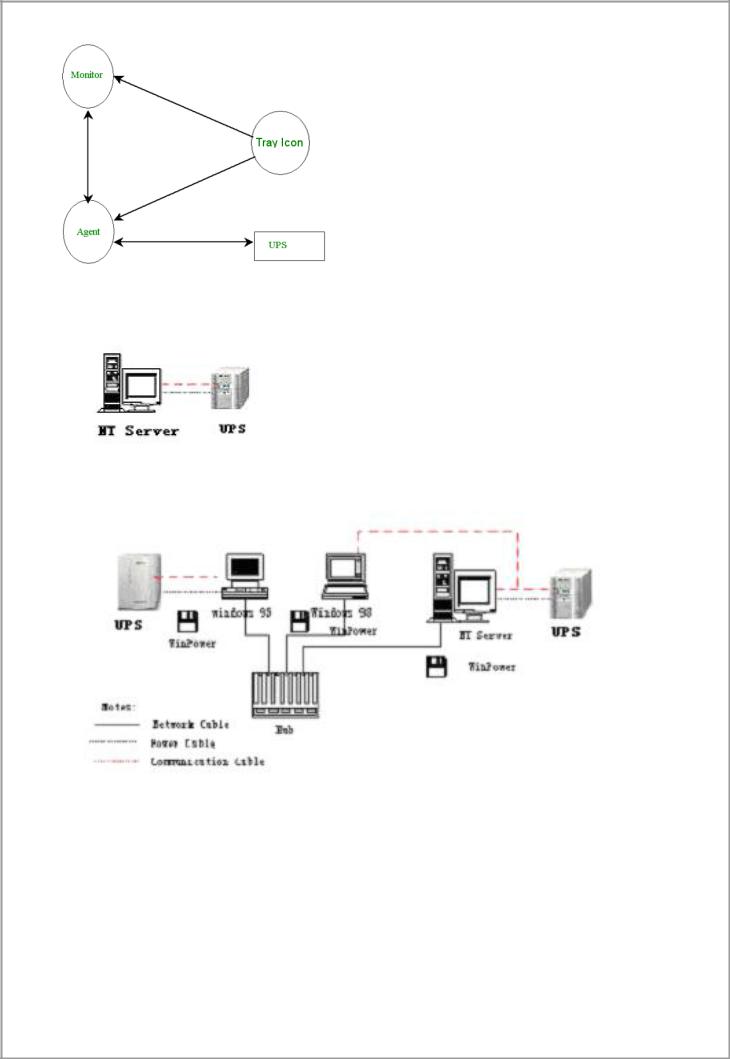
Diagram 1-2-2
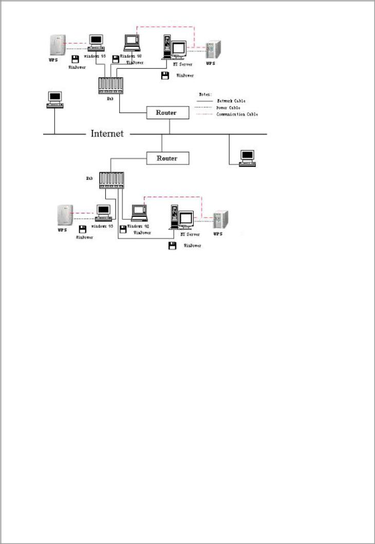
3. Winpower Application Range
Application of stand alone computers refers to the following Diagram 1-3-1
Diagram 1-3-1
Application in the LAN refers to the following Diagram 1-3-2
(Diagram 1-3-2)
Application in the Internet refers to the following Diagram 1-3-3
5
(Diagram 1-3-3)
4. WinPower Functions & Advantages
When Agent start, it will run continuously, protect your equipment in every moment.
Uninstall easily and clearly with no trace. Never increase spending on system and is Green software.
You can have a panoramic view of all the information. The information of utility power, UPS, loads and battery is shown on the same window and you can take in everything in a glance.
With the function of auto searching and telemonitoring any UPS in LAN.
With the function of manual searching and telemonitoring any UPS in Internet. With security protection function. The system administrator password can be set to prevent others from sabotaging. Only the system administrator can have the full access, other users can only view.
With the function of data auto protection. It can close most of the running applications and save the related files.
With the function of time turning on and off the UPS, which can give maximum protection to your computer system.
With the function of time self test of the UPS, which provide maximum protection to your UPS system.
With the function of network shutdown, which supply your network system maximum protection.
With the function of data logging (including UTILITY POWER, UPS, LOAD and BATTERY) and event logging, so that the system administrator can carry out the UPS system daily maintenance.
6

Flexible means of information transfer let you know the UPS status at any moment and at everywhere, never miss any one because of the change of time and place.
With the function of broadcasting messages to every users in the network. With the function of sending messages via pager.
With the function of sending messages by EMAIL.
With the function of sending messages via mobile phone sending SMS.
7

Chapter 2 Winpower Installation, Start & Uninstall
1. System Requirement
128 MB physical memory at least (256MB is recommended). 160 MB at least hard disk space.
The user is required to have the access of administrator.
More than 256 colors and 800 * 600 resolution or above display is recommended.
For Mac OS X, Linux or Unix operating system, the user must have the access of super user.
TCP/IP protocol must be installed to support network management.
An available communication port (RS-232 Serial Port or USB port) is needed while connecting to UPS with a special communication cable.
Platforms supported by Winpower include the following:
Windows 98
Windows me
Windows NT 4.0 (sp6)
Windows 2000
Windows 2003
Windows XP
Linux
Solaris/Sparc 2.6, 7, 8, 9
Solaris/Intel 2.6, 7, 8, 9
HP-UX 11.x, 11i.x
AIX 4.3.x, 5.x
Mac PPC OSX
Compaq Tru64 Alpha
SCO UnixWare 7.1.1, 7.1.3
SCO Unix 8.0
FreeBSD x86
SGI Irix 6.5.x
2. Winpower Installation Steps
Enter the right directory of the CD according your platform type.
For GUI mode environment:
Insert the Winpower CD, find out the operate system of your computer( such as
Windows) in the CD directory, Refer to Diagram 2-2-1 below:
Diagram 2-2-1
8

For Windows platform, enter \Windows\Disk1\InstData\VM directory, run setup.exe to start the installation. Refer to the following diagram 2-2-2:
Diagram 2-2-2
For Mac OS X platform, enter \MacOSX\Disk1\InstData directory, double click the setup.app to start the installation. Refer to the following diagram 2-2-3:
Diagram 2-2-3
For other operating system, execute ./setup.bin or setup_console.bin, Refer to the following diagram 2-2-4:
Diagram 2-2-4
Read the introduction , Refer to the following diagram 2-2-5
9

Diagram2-2-5
Click “Next”button ,and input the Serial Number, Refer to the following diagram 2-2-6
Diagram 2-2-6
10
Click “Next”button ,and choose install folder , Refer to the following diagram 2-2-7
Diagram 2-2-7
Review the Pre-installation Summary, Refer to the following diagram 2-2-8
11

Diagram 2-2-8
Installing, Refer to the following diagram 2-2-9
Diagram 2-2-9
When the installation program is completed, click Done. Refer to the following diagram
2-2-10
12

Diagram 2-2-10
Clicking on the button “Done”. If the software is installed successful, ”Winpower” application can be found in the Start menu\Programs\, refer to the following diagram 2- 2-11.
Diagram 2-2-11
For console mode environment:
1.Enter the directory according the system and run setup.bin or setup_console.bin to start the installation program.
Note: For UnixWare platform, make sure JRE1.3.1 has been install in your system, then enter the /GenericUnix directory to start the setup.
2.Read the information provided, then press ENTER to continue the installation.
13

3.When the installation program is completed, click Done.
4.Reboot the Linux and Unix system after installation.
The installation will set enviroment variables for Winpower in /etc/profile file.(details see 'Set environment variable' below)
Reboot the system in order to make this settings valid.
Note: For UnixWare platform, make sure JRE1.3.1 has been install in your system, then enter the /GenericUnix directory to start the setup.
3. Start/Stop Winpower
In Windows operating system
Start Agent: Run the Winpower form Start\Progrom\Winpower will start the
TrayIcon and Agent.
Refer to the Diagram 2-3-1 below
Diagram 2-3-1
The Agent can be start by the following 3 methods:
1) Run the Winpower form Start\Progrom\Winpower will start the TrayIcon and
Agent.refer to Diagram 2-3-1.
2)Right click the Agent icon showing on the bottom right corner of the display and select the ‘Start Agent’item.refer to Diagram 2-3-2.
Diagram 2-3-2
3) For Windows operate system,Agent can be startup automaticallywhen the computer startup.
Start Monitor:
Method One: Right click the TrayIcon and select the "Start Monitor" menu item.refer to Diagram 2-3-3.
14

Diagram 2-3-3
Stop the Agent: Right click the TrayIcon and select the "Stop Agent" menu item.
Refer to the following diagram 2-3-4
Diagram 2-3-4
In Mac OS X
Start Agent:
Agent is auto stated on system boot. You can also start it by enter install directory and execute command:
./agent start
Start Monitor:
Double click the executable monitor link in "Applications/Winpower" directory to start Monitor.
You can also start it in terminal by enter install directory and execute command:
./monitor
Stop Agent:
Enter install directory and execute command:
./agent stop
In Linux and UnixWare:
Start Agent:
enter /opt/upspilot directory and execute command:
./agent start
Start Monitor:
enter /opt/upspilot directory and execute command:
./monitor
Stop Agent:
enter /opt/upspilot directory and execute command:
./agent stop
4. Uninstall Winpower
In Windows operating system
There are two kinds of methods for Uninstalling Winpower
One is to click “Uninstall Winpower” icon in “Start/Program/Winpower” with left mouse button, refer to Diagram 2-4-1 below:
15

Diagram 2-4-1
The other one is to left click “Control Panel/”Add/Remove
Program”/Change/Remove(C)” button, see Diagram 2-4-2 below:
Diagram 2-4-2
Note: Before uninstall Winpower,your must stop all Winpower program first! Otherwise it can't be uninstall completely.
After left click, the Uninstall Program will pop up a dialog shown on Diagram 2- 4-3 as below:
16

Diagram 2-4-3
Click the “Uninstall” button to begin to uninstall Winpower software, refer to the following diagram 2-4-4
Diagram 2-4-4
17

Click “Done” button and Winpower has been uninstalled completely. Refer to the following diagram 2-4-5
Diagram 2-4-5
Note:Before uninstall Winpower,your must stop all Winpower program first! Otherwise it can't be uninstall completely.
In Mac OS X:
Double click the Uninstall link in "Applications/Winpower" directory or enter "/opt/upspilot" directory and execute command:
./Uninstall
In Linux and UnixWare:
Open the Terminal, enter "/opt/upspilot" directory and execute command:
./Uninstall
18

Chapter 3 Winpower User Interface
1. "Winpower Manage" window
Winpower Monitor shows "Winpower Manager" window which display a list of all Agents within the LAN.
There is a tree view on the left side of the window that displays a hierarchical list of items, such as ‘Root’,‘networks’,the Agents,the COM port,USB port and the UPS models. By clicking an item, the user can expand or collapse the associated list of subitems, Refer to the following diagram 3-1-1:
Diagram 3-1-1
If you select one of the UPS model from the UPS List, details about the UPS will be displayed on the right side, Refer to the following diagram 3-1-2:
1.The middle area displays the UPS Status Figure. The UPS Status Figure is different for various UPS status and UPS type.
2.The upper area displays the UPS Status Description and recommendation, and the
Agent system times with right align.
3.The lower area displays the last two events information.
4.It is able to minimize the window by clicking the minimum button on the top right corner of the window.
5.It is able to exit from the system by clicking “X”.
19

Diagram 3-1-2
Illustration for UPS Status information bar:
The UPS status figure consists of five parts: AC LINE, UPS, BATTERY LOAD and BYPASS. Each part is connected with power cord.
2. Menu and Dialog
1) Auto Search UPS
When user select " Auto Search UPS " menu item from "System" Menu, Winpower will start searching for the UPS connect with the computer’s serial port. See the following diagram 3-2-1-1 and diagram 3-2-1-2.
Diagram 3-2-1-1
20
Diagram 3-2-1-2
By clicking the item in the tree view,user will get the information as below, see the following diagram 3-2-1-3:
1)All the computer running Winpower Agent on the LAN.
2)UPS COM Port or USB Port.
3)the model type of UPS to which the Agent is connecting.
4)The Current Status of the Agent which user select in the tree view .
21

Diagram 3-2-1-3
2) “Administrator” Dialog
"Administrator" dialog can be opened by clicking “Act as Administrator” in the “System” menu. See the following diagram 3-2-2. Enter the administrator password in the edit box and then click “OK” button. If the password is not correct, the system will pop up a message dialog to prompt users that the user password is not correct. If the password is correct, users can get the administrator access right and set up the Agent.
Note :Initial password is “Administrator”.
Diagram 3-2-2
3) "Administrator Password Settings" Dialog
“Administrator Password Settings” dialog can be opened from the “Modify Administrator
Passowrd” menu item of “System” menu. Refer to the following diagram 3-2-3:
Diagram 3-2-3
Administrator password only can be set by super user in local machine. If your are not an super user yet, the "Administrator" Dialog will pop up first for you to log on as administrator.
Users need to enter a new password in the "New Password" text box and reenter the new password in the "Confirm Password" text box. If the passwords are not consistent with each other, a message dialog will pop up to notify the users that the password is not correct and request the users to enter it once again. If the passwords are consistent with each other and the button "OK" is selected, the new password will be accepted by the system.
22

4) "Event log Viewer" Dialog
"Event Log Viewer" Dialog will show when user select "Event Log" menu item from
"Logs" Menu or click buttons from toolbar, or click the “View log” button of event log in the “Record Setting” dialog, then the “Event Log” dialog will pop up. See the following
Diagram 3-2-4. The dialog displays a list of history events.
Diagram 3-2-4
User can select the check box “Delete” and click "Delete" button to remove the selected events.
Users can click “Close” button to close the dialog.
Users can click "Purge All" button to delete all of the events.
Note: If “Delete” and "Purge All" button is in invalid condition, which means your access right to the current Agent is “Read Only”, you can not carry out the operation. You may log in as super user through the “Act as Administrator” menu.
5) "Data log Viewer" Dialog
"Data Log Viewer" Dialog will popup when users select "Data Log" menu item from
"Logs" Menu , or click buttons from toolbar or click “View log” button of data log in the “Record Setting” dialog. Refer to the following Diagram 3-2-5, the history data will appear in this dialog.
Users can click “Next”, “Prev”, “Home” and “End” button to display the data log.
23

Diagram 3-2-5
User can select the check box “Delete” and click "Delete" button to remove the selected data log.
Users can click “Close” button to close the dialog.
Users can click "Purge All" button to delete all of the data.
Note: If “Delete” and "Purge All" button is in invalid condition, which means your access right to the current Agent is “Read Only” and you cannot carry out these operations. You may log in as super user through the “Act as Administrator” menu.
6) “Record Setting” Dialog
“Record Setting” dialog can be opened from the “Record Setting” menu item of “Logs” menu. Refer to the following Diagram 3-2-6-1:
Diagram 3-2-6-1
The default value of the maximum file length of Event Log Viewer is 32KB (The maximum value is 1MB)
Click the “View Log” button of the event log in the “Record Setting” dialog (Refer to the following Diagram 3-2-6-2) to pop up the “Event Log Viewer” dialog (Refer to the following diagram 3-2-6-3)
24

Diagram 3-2-6-2
Diagram 3-2-6-3
Click the “Settings” button of the event log in the “Record Setting” dialog (Refer to the following diagram 3-2-6-4) to pop up the “Event Action” dialog, refer to the following diagram 3-2-6-5.
25
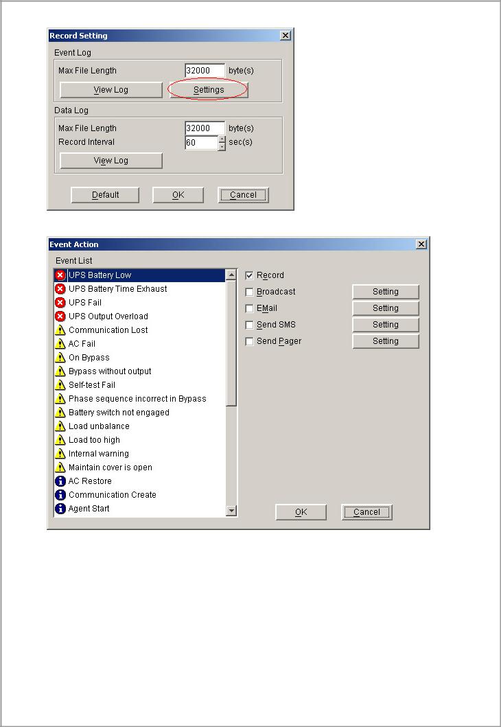
Diagram 3-2-6-4
Diagram 3-2-6-5
The default value of the “Maximum file length” in the “Data Log Viewer” is 32KB (the maximum is 1MB).
The default value of record interval in the “Data Log Viewer” is 60 second (the maximum is 3600 second).
Click the “View Log” button of data log in the “Record Setting” dialog (refer to the following diagram 3-3-5-6) to pop up the “Data Log Viewer” dialog (refer to the following diagram 3-2-6-7).
26

Diagram 3-2-6-6
Diagram 3-2-6-7
Note: Click “Default” button and the parameters in this page will become default. If the “OK” button is in invalid condition, which means your access right to the current Agent is “Read Only” and you cannot setup the parameters. You may log in as a super user through the “Act as Administrator” menu.
7) "UPS Control Parameters" Dialog
"UPS Control Parameters" Dialog will pop up when user select "UPS Control Parameters" item from “UPS” menu.
For ON-LINE UPS,Refer to the following diagram 3-2-7-1:
27
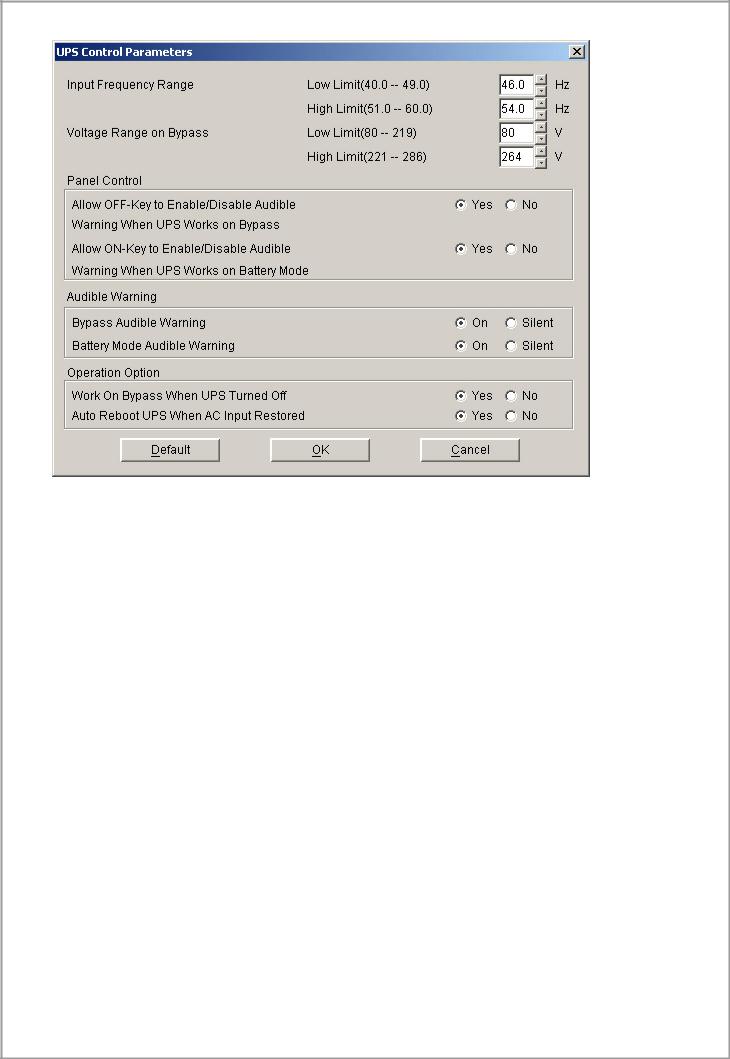
Diagram 3-2-7-1
See the following table 3-2-7-1:
Parameter |
Unit |
Maximum |
Minimum |
Default |
High limit of |
Hz |
60.0 (for 50Hz |
51.0 (for 50Hz |
54.0 (for 50Hz |
input frequency |
|
system) |
system) |
system) |
on bypass |
|
70.0 (for 60Hz |
61.0 (for 60Hz |
64.0 (for 60Hz |
|
|
system) |
system) |
system) |
Low limit of |
Hz |
49.0 (for 50Hz |
40.0 (for 50Hz |
46.0 (for 50Hz |
input frequency |
|
system) |
system) |
system) |
on bypass |
|
59.0 (for 60Hz |
50.0 (for 60Hz |
56.0 (for 60Hz |
|
|
system) |
system) |
system) |
High limit of |
V |
286 (for 1~3K |
221 (for 1~3K |
264 (for 1~3K |
input voltage on |
|
220V UPS) |
220V UPS) |
220V UPS) |
bypass |
|
132 (for 1~3K |
110(for 1~3K |
132 (for 1~3K |
|
|
110V UPS) |
110V UPS) |
110V UPS) |
|
|
261 (for 6~20K |
231 (for 6~20K |
261 (for 6~20K |
|
|
UPS) |
UPS) |
UPS) |
Low limit of |
V |
219 (for 1~3K |
80 (for 1~3K |
80 (for 1~3K |
input voltage on |
|
220V UPS) |
220V UPS) |
220V UPS) |
bypass |
|
110 (for 1~3K |
40 (for 1~3K |
50 (for 1~3K |
|
|
110V UPS) |
110V UPS) |
110V UPS) |
|
|
209 (for 6~20K |
140 (for 6~20K |
176 (for 6~20K |
|
|
UPS) |
UPS) |
UPS) |
ON button can |
- |
- |
- |
Yes |
control battery |
|
|
|
|
mode audible |
|
|
|
|
warning |
|
|
|
|
OFF button can |
- |
- |
- |
Yes (for 1~3K |
control bypass |
|
|
|
UPS) |
|
|
28 |
|
|
 Loading...