

Page 1

be certain.
m
SWIFT® 50 GLP Sensor
Product Information
Spinning Wheel Integrated Force Transducer
For Medium and Heavy Trucks
100-162-722 E
Page 2

Copyright information © 20012 MTS Systems Corporation. All rights reserved.
Trademark information MTS, SWIFT, T estStar, TestWare, MTS Remote Parameter Control, and RPC are
registered trademarks of MTS Systems Corporation within the United States.
These trademarks may be protected in other countries.
All other trademarks or service marks are property of their respective owners.
Proprietary information Software use and license is governed by MTS’s End User License Agreement
which defines all rights retained by MTS and granted to the End User. All
Software is proprietary, confidential, and owned by MTS Systems Corporation
and cannot be copied, reproduced, disassembled, decompiled, reverse
engineered, or distributed without express written consent of MTS.
Software validation and
verification
Publication information
MTS software is developed using established quality practices in accordance
with the requirements detailed in the ISO 9001 quality standards. Because MTSauthored software is delivered in binary format, it is not user accessible. This
software will not change over time. Many releases are written to be backwards
compatible, creating another form of verification.
The status and validity of MTS’s operating software is also checked during
system verification and routine calibration of MTS hardware. These controlled
calibration processes compare the final test results after statistical analysis
against the predicted response of the calibration standards. With these established
methods, MTS assures its customers that MTS products meet MTS’s exacting
quality standards when initially installed and will continue to perform as intended
over time.
Manual Part Number Publication Date
100-162-722 A March 2006
100-162-722 B April 2006
100-162-722 C January 2007
100-162-722 D January 2009
100-162-722 E June 2012
Page 3

Contents
Technical Support 5
How to Get Technical Support 5
Before You Contact MTS 5
If You Contact MTS by Phone 7
Problem Submittal Form in MTS Manuals 8
Preface 9
Before You Begin 9
Conventions 10
Documentation Conventions 10
Hardware Overview 13
Overview 14
Spinning Applications (Track or Road) 16
Non-spinning Applications (Laboratory) 17
Construction 18
Design Features 21
Coordinate System 22
Specifications 24
Calibration 26
Interfacing with RPC 27
Installation 29
Hazard Icons 30
Road and Track Vehicles 31
Attaching SWIFT Components to the Vehicle 36
Attaching SWIFT and Wheel Assembly to the Vehicle 40
Attaching SWIFT Components to the Fixturing 48
Analyzing SWIFT Data 53
The Data 54
SWIFT 50 GLP Sensors
3
Page 4

Fx Data (Longitudinal Force) 55
Fz Data (Vertical Force) 57
Mx Data (Overturning Moment) 58
My Data (Brake Moment) 61
Acceleration and Braking Events Example 63
Slalom Curve Driving Example 65
Maintenance 67
Transducer 68
Cables 69
Troubleshooting 71
Assembly Drawings 83
Cable Drawings 84
SWIFT 50 GLP Mechanical Drawings 95
4
SWIFT 50 GLP Sensors
Page 5

Technical Support
How to Get Technical Support
Start with your
manuals
Technical support
methods
The manuals supplied by MTS provide most of the information you need to use
and maintain your equipment. If your equipment includes software, look for
online help and README files that contain additional product inform ation.
If you cannot find answers to your technical questions from these sources, you
can use the Internet, e-mail, telephone, or fax to contact MTS for assistance.
MTS provides a full range of support services after your system is installed. If
you have any questions about a system or product, contact Technical Support in
one of the following ways.
www.mts.com The web site provides access to our technical support staff by means of an online
form:
www.mts.com > Contact MTS > Service & Technical Support button
E-mail tech.support@mts.com
Telephone MTS Call Center 800-328-2255
Weekdays 7:00 A.M. to 5:00 P.M., Central Time
Fax 952-937-4515
Please include “Technical Support” in the subject line.
Outside the U.S. For technical support outside the United States, contact your local sales and
service office. For a list of worldwide sales and service locations and contact
information, use the Global MTS link at the MTS web site:
www.mts.com > Global MTS > (choose your region in the right-hand
column) > (choose the location closest to you)
Before You Contact MTS
MTS can help you more efficiently if you have the following information
available when you contact us for support.
Know your site
number and system
number
SWIFT 50 GLP Sensors Technical Support
The site number contains your company number and identifies your equipment
type (such as material testing or simulation). The number is typically written on a
label on your equipment before the system leaves MTS. If you do not know your
MTS site number, contact your sales engineer.
Example site number: 571167
When you have more than one MTS system, the system job number identifies
your system. You can find your job number in your order pape rwork.
Example system number: US1.42460
5
Page 6

Know information from
prior technical
If you have contacted MTS about this problem before, we can recall your file
based on the:
assistance
• MTS notification number
• Name of the person who helped you
Identify the problem Describe the problem and know the answers to the following questions:
• How long and how often has the problem occurred?
• Can you reproduce the problem?
• Were any hardware or software changes made to the system before the
problem started?
• What are the equipment model numbers?
• What is the controller model (if applicable)?
• What is the system configuration?
Know relevant
computer information
Know relevant
software information
For a computer problem, have the following information available:
• Manufacturer’s name and model number
• Operating software type and service patch information
• Amount of system memory
• Amount of free space on the hard drive where the application resides
• Current status of hard-drive fragmentation
• Connection status to a corporate network
For software application problems, have the following information available:
• The software application’s name, version number, build number, and (if
available) software patch number. This information can typically be found
in the About selection in the Help menu.
• The names of other applications on your computer, such as:
– Anti-virus software
– Screen savers
– Keyboard enhancers
– Print spoolers
Technical Support
6
– Messaging applications
SWIFT 50 GLP Sensors
Page 7

If You Contact MTS by Phone
A Call Center agent registers your call before connecting you with a technical
support specialist. The agent asks you for your:
• Site number
• Name
• Company name
• Company address
• Phone number where you can be reached
If your issue has a notification number, please provide that number. A new issue
will be assigned a unique notification number.
Identify system type To enable the Call Center agent to connect you with the most qualified technical
support specialist available, identify your system as one of the following types:
• Electromechanical material test system
• Hydromechanical material test system
• Vehicle test system
• Vehicle component test system
Be prepared to
troubleshoot
Write down relevant
information
After you call MTS logs and tracks all calls to ensure that you receive assistance for your
• Aero test system
Prepare to perform troubleshooting while on the phone:
• Call from a telephone close to the system so that you can implement
suggestions made over the phone.
• Have the original operating and application software media available.
• If you are not familiar with all aspects of the equipment operation, have an
experienced user nearby to assist you.
In case Technical Support must call you:
• Verify the notification number.
• Record the name of the person who helped you.
• Write down any specific instructions.
problem or request. If you have questions about the status of your problem or
have additional information to report, please contact Technical Support again and
provide your original notification number.
SWIFT 50 GLP Sensors Technical Support
7
Page 8

Problem Submittal Form in MTS Manuals
Use the Problem Submittal Form to communicate problems with your software,
hardware, manuals, or service that are not resolved to your satisfaction through
the technical support process. The form includes check boxes that allow you to
indicate the urgency of your problem and your expectation of an acceptable
response time. We guarantee a timely respon se—your feedback is important to
us.
Access the Problem Submittal Form:
• In the back of many MTS manuals (postage paid form to be mailed to MTS)
• www.mts.com > Contact Us > Problem Submittal Form button (electronic
form to be e-mailed to MTS)
Technical Support
8
SWIFT 50 GLP Sensors
Page 9

Before You Begin
Preface
Before You Begin
Safety first! Before you use your MTS product or system, read and understand the Safety
manual and any other safety information provided with your system. Improper
installation, operation, or maintenance can result in hazardous conditions that can
cause severe personal injury or death, or damage to your equipment and
specimen. Again, read and understand the safety information provided with your
system before you continue. It is very important that you remain aware of
hazards that apply to your system.
Other MTS manuals In addition to this manual, you may receive additional manuals in paper or
electronic form.
You may also receive an MTS System Documentation CD. It contains an
electronic copy of the manuals that pertain to your test system, such as:
• Hydraulic and mechanical component manuals
• Assembly drawings
• Parts lists
• Operation manual
• Preventive maintenance manual
Controller and application software manuals are typically included on the
software CD distribution disc(s).
Model 505G2.60 - 505G2.180 SilentFlo™ HPU Preface
9
Page 10

Conventions
DANGER
WARNING
CAUTION
Conventions
Documentation Conventions
The following paragraphs describe some of the conventions that are used in your
MTS manuals.
Hazard conventions Hazard notices may be embedded in this manual. These notices contain safety
information that is specific to the activity to be performed. Hazard notices
immediately precede the step or procedure that may lead to an associated hazard.
Read all hazard notices carefully and follow all directions and recommendations.
Three different levels of hazard notices may appear in your manuals. Following
are examples of all three levels.
Note For general safety information, see the safety information provided with
your system.
Danger notices indicate the presence of a hazard with a high level of risk which,
if ignored, will result in death, severe personal injury, or substantial property
damage.
Warning notices indicate the presence of a hazard with a medium level of risk
which, if ignored, can result in death, severe personal injury, or substantial
property damage.
Caution notices indicate the presence of a hazard with a low level of risk which,
if ignored, could cause moderate or minor personal injury or equipment damage,
or could endanger test integrity.
Notes Notes provide additional information about operating your system or highlight
easily overlooked items. For example:
Note Resources that are put back on the hardware lists show up at the end of
the list.
Special terms The first occurrence of special terms is shown in italics.
Illustrations Illustrations appear in this manual to clarify text. They are examples only and do
Electronic manual
conventions
Preface
10
not necessarily represent your actual system configuration, test application, or
software.
This manual is available as an electronic document in the Portable Document
File (PDF) format. It can be viewed on any computer that has Adobe Acrobat
Reader installed.
Model 505G2.60 - 505G2.180 SilentFlo™ HPU
Page 11

Documentation Conventions
Hypertext links The electronic document has many hypertext links displayed in a blue font. All
blue words in the body text, along with all contents entries and index page
numbers, are hypertext links. When you click a hypertext link, the application
jumps to the corresponding topic.
Model 505G2.60 - 505G2.180 SilentFlo™ HPU Preface
11
Page 12

Documentation Conventions
12
Preface
Model 505G2.60 - 505G2.180 SilentFlo™ HPU
Page 13

Hardware Overview
Contents Overview 14
Spinning Applications (Track or Road) 16
Non-spinning Applications (Laboratory) 17
Construction 18
Design Features 21
Coordinate System 22
Specifications 24
Calibration 26
Interfacing with RPC 27
SWIFT 50 GLP Sensors Hardware Overview
13
Page 14

Overview
Data
S50-001
Track or Road
Laboratory Simulation
WARNING
Overview
The MTS Spinning Wheel Integrated Force Transducer (SWIFT®) sensor is a
light-weight, easy-to-use transducer that enables you to conduct faster, less
expensive data acquisition and road simulation testing.
The transducer is designed for use on the test track and public roads, as well as,
in the test laboratory. It attaches to the test vehicle or an MTS Series 329 Road
Simulator using an adapter and a modified wheel rim.
You can achieve excellent data correlation using the same transducer and vehicle
on the test track or public road and on a road simulator. It is available in various
sizes and materials to fit various vehicle and loading requirements.
Parts Replacement,
Disassembly, and Care
Driving a vehicle with SWIFT sensors mounted on it will change the
handling characteristics of the vehicle.
Driving a vehicle configured in this way on public roads can pose
unexpected dangers to pedestrians and other vehicle traffic.
Only authorized, licensed drivers, who are experienced driving a vehicle with
SWIFT sensors mounted on it, should be allowed to operate the vehicle on public
roads. Drive the vehicle with the SWIFT sensor attached on closed courses only
until you have proper experience.
The SWIFT sensor assembly, Transducer Interface box, and the accessory
components have no user serviceable parts. These components should not be
disassembled other than as outlined in “Troubleshooting” beginning on page 71.
Hardware Overview
14
SWIFT 50 GLP Sensors
Page 15

Overview
CAUTION
Do not disassemble the SWIFT sensor, Transducer Interface (TI) electronics,
and accessory components.
The SWIFT sensor, TI electronics, and accessory components are not
intended to be disassembled, other than as outlined in “Troubleshooting”.
Disassembling or tampering with these components may result in damage to the
sensor, loss of watertight seal, and voiding of the warranty.
• The sensor assembly should be returned to MTS annually for recalibration
and inspection.
• Clean the sensor assembly after each use, as described in Maintenance
beginning on page 67, especially if it is exposed to corrosive or abrasive
material, such as salt or sand.
• Read and follow all warnings and cautions affixed to the transducer and in
this manual especially those warnings and cautions that deal with
installation, use, inspection and maintenance of the transducer.
The SWIFT sensor
assembly should not:
• Be bumped into hard surfaces or objects while driving the vehicle.
• Be driven through grass or brush that is taller than the bottom edge of the
sensor.
• Be exposed to loads that exceed the full scale calibrated ranges, as listed in
“Specifications” on page 24.
• Be used if the integrity of the sealed cover has been compromised or the
warning labels removed.
• Be used if the sensor assembly shows indications of damage (such as dents,
bent slip ring bracket arms, a bent anti-rotate assembly, etc.).
• Be used if any part of the assembly has been modified without explicit,
written authorization from MTS.
SWIFT 50 GLP Sensors Hardware Overview
15
Page 16
Spinning Applications (Track or Road)
Customer Supplied
Power Supply
Customer Supplied
Data Recorder
Transducer Interface
(TI)
Transducer Signals
Output
Signals
S50-002
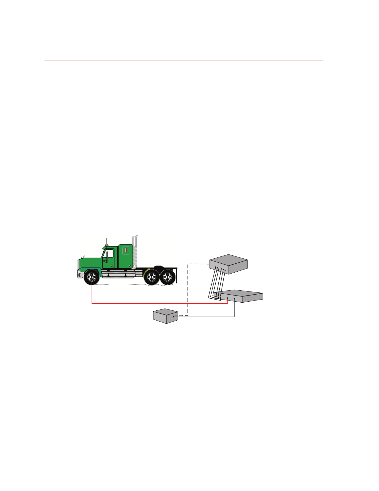
Spinning Applications (Track or Road)
The SWIFT sensor can be used for road load data acquisition (RLDA)
applications:
• Durability
• Noise, Vibration and Harshness (NVH)
• Ride and Handling
• Tire Performance
The transducer is durable enough to withstand harsh road testing and data
acquisition environments. The transducer is splash resistant and suitable for use
in conditions where the test vehicle will encounter occasional standing or running
water, or will be exposed to precipitation. However, it should not be submerged.
In a typical spinning application, the transducer is mounted on a modified rim of
a tire on a test vehicle, as shown in the following figure. The Transducer
Interface (TI), customer supplied power supply, and data recorder can be located
inside the vehicle or in the trunk.
Note For track applications, the power supply is usually the vehicle’s power
system or an auxiliary battery.
Spinning Application (Track or Road)
Hardware Overview
16
SWIFT 50 GLP Sensors
Page 17

Non-spinning Applications (Laboratory)
Power Supply (with 4
connections)
Customer-Supplied
Test Control System
Transducer Interface
(TI)
Transducer Signals
Output
Signals
PC Communication
S50-003
Non-spinning Applications (Laboratory)
The SWIFT sensor can be fully integrated into the simulation process, since it is
an optimal feedback transducer for use with MTS Remote Parameter Control
®
) software. The transducer takes data at points where fixturing inputs are
(RPC
located rather than at traditional instrumentation points along the vehicle’s
suspension. Using the SWIFT sensor saves you instrumentation time, and fewer
iterations are required to achieve good simulation accuracy.
Measuring spindle loads allows engineers to generate generic road profiles.
Generic road profiles are portable across various vehicle models, do not require
new test track load measurements for each vehicle, and eliminate additional
RLDA tasks.
Four of the six loads measured by the transducer directly correlate to the MTS
Model 329 Road Simulator inputs: vertical force, longitudinal force, lateral force,
and braking input.
The same transducers used to collect road data can be mounted directly in the
wheel adapters of the MTS Model 329 Road Simulator. For durability testing, a
titanium SWIFT sensor can be used for iterations within the RPC process. The
titanium SWIFT sensor should then be removed for the durability cycles, to
preserve its fatigue life. It can be replaced by an adapter plate, available from
MTS, to duplicate the mass and center of gravity of the actual SWIFT sensor. If a
SWIFT sensor is to be used during full durabilit y tests, we suggest using the
stainless steel model, which has a higher fatigue rating.
®
In a typical non-spinning application, a SWIFT sensor is mounted on a road
simulation test fixture, as shown in the following figure.
Non-spinning Application (Laboratory Simulation)
SWIFT 50 GLP Sensors Hardware Overview
17
Page 18

Construction
Slip Ring
Bracket
(with encoder)
Lug Nuts and
Shim Washers (10)
Spindle Adapter
Spacer
Transducer
Modified
Wheel Rim
(front wheel)
S50-008
Spacer-to-Transducer
Fasteners
Rim-to-Transducer
Assembly Fasteners
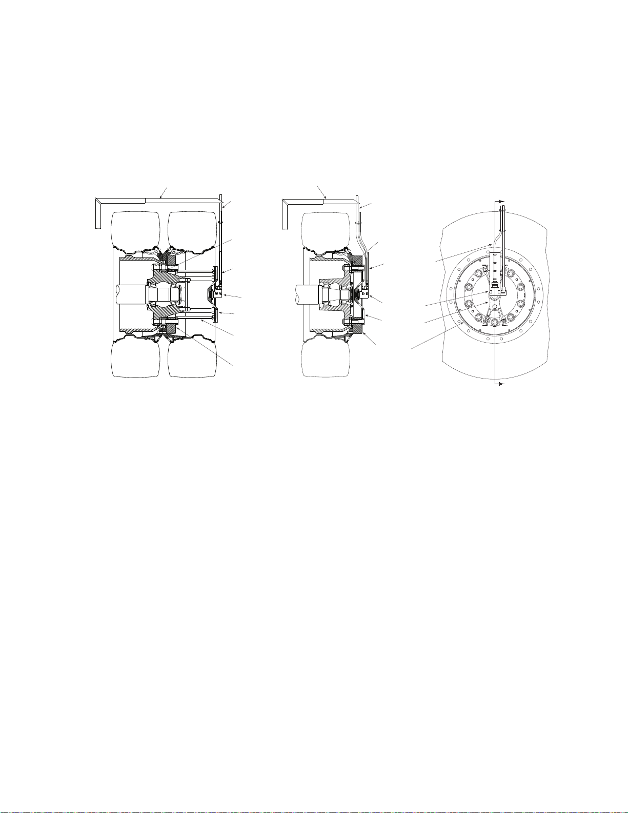
Construction
The SWIFT sensor has one-piece construction for outstanding fatigue life, low
hysteresis, and high stiffness. Its compact package has a minimal effect on inertia
calculations, and a minimal dynamic effect on the test vehicle.
The transducer can be used for developing conventional durability tests on the
MTS Model 329 Road Simulator. Normally, the transducer is replaced with an
equivalent wheel adapter after the simulation drive signals are developed and
prior to the start of the test.
The SWIFT sensor includes several mechanical and electrical components.
Transducer The transducer attaches directly to a modified wheel rim. On the test track
vehicle, it spins with the wheel. It does not spin on a road simulator. The
transducer is available in two materials: titanium, for spinning applications,
where the priority is light weight, and stainless steel, for non-spinning
applications, where the priority is maximum load capacity and durability.
The transducer’s unibody design means there are no multiple parts welded or
screwed together.
The transducer has four beams with strain gages that measure six orthogonal
outputs:
Fx—longitudinal force
Fy—lateral force
Fz—vertical force
Mx—overturning moment
My—acceleration and brake torque
Mz—steering moment
It has onboard conditioning and amplifiers to improve the signal-to-noise ratio.
Hardware Overview
18
SWIFT 50 GLP Sensors
Page 19
Construction
Dual Rim Configuration Front Rim Configuration
Slip Ring
Slip Ring
Anti-Rotate
Assembly
Anti-Rotate
Assembly
SWIFT 50
Transducer
SWIFT 50
Transducer
Tire Tire
Tire
Spindle
Adapter
Spacer
Spindle
Adapter
Spacer
Anti-Rotate
Mounting Bracket
(customer supplied)
Anti-Rotate
Mounting Bracket
(customer supplied)
Slip-Ring
Bracket
Slip Ring
Bracket
Transducer
Interface
Cable
Transducer
Interface
Cable
S50-004a
Slip-Ring
Extension
Bracket
(Component configuration is typical. Your specific
configuration might vary slightly.)
Spindle adapter spacer The spindle adapter spacer attaches to the inner diameter of the transducer,
allowing you to place it at the original position of the spindle face of the vehicle.
The spindle adapter spacer enables you to maintain the original position of the
tire on the vehicle (the tire will not protrude from the vehicle) while the
transducer is attached to the vehicle. In addition, the spindle adapter spacer helps
minimize brake heat from being transferred to the transducer.
Components Set Up for Test Track
Slip-ring bracket The slip-ring bracket is used to attach the slip ring to the transducer. It has
internal wiring that provides excitation power to the strain gage bridges and
brings signals out from the transducer to the slip ring.
Encoder An encoder measures the angular position of the transducer. The SWIFT sensor
uses an optical encoder, integrated into the slip ring assembly, that counts off
“ticks” to measure the angular position as the wheel rotates. It measures 2048
(512 plus quadrature) points per revolution (ppr) with a resolution of 0.18
Slip ring The slip ring allows you to output the transducer bridge signals and angular
SWIFT 50 GLP Sensors Hardware Overview
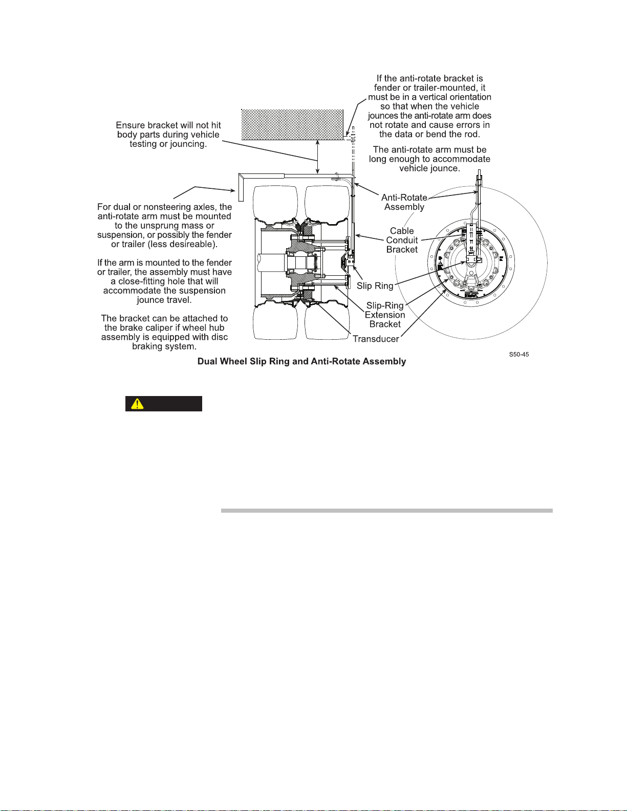
Anti-rotate device The anti-rotate device is attached to the slip ring and the vehicle’ s suspension (or
degrees and an accuracy of 0.18 degrees.
position to the TI. A transducer data cable attaches from the slip ring to the back
panel of the TI. The slip ring is not used for non-spinning applications.
other non-rotating point). It is able to move up and down with the vehicle. Its
primary function is to provide a fixed reference point for the optical encoder. Its
secondary function is to prevent the cable from rotating with the wheel and
becoming tangled or breaking.
19
Page 20

Construction
The anti-rotate device is mainly used for road data collection. Although it can
also be used for short periods of time on a road simulator. MTS does not
recommend this use. Due to the extreme fatigue loading characteristics of
durability testing on road simulators, we suggest that you either remove the slip
ring assembly before installing the vehicle on a road simulator, or use it only for
iteration passes, then promptly remove it.
The anti-rotate device should be configured such that no loading occurs to the
slip ring throughout all loading and suspension travel. This means that when you
attach the anti-rotate device to the vehicle, you must consider all possible motion
of the suspension. The anti-rotate device should not bump against the wheel well
at any time; any jarring of the anti-rotate arm will damage the slip ring. For
steering axles, the anti-rotate bracket must be mounted to part of the unsprung
suspension that steers with the tire, such as the brake caliper. For additional antirotate device mounting recommendations, refer to the Anti-Rotate Customer/
User Assembly drawing at the back of this manual.
Transducer Interface
(TI)
Additional
components
The TI conditions the power supply, and uses previously stored calibration values
to convert the eight bridge outputs and the encoder signal to six non-rotating
analog outputs (Fx, Fy, Fz, Mx, My, Mz) plus an angle output. The force and
moment outputs have a value of 10 V full scale, unless a different full-scale
output is requested by a customer. The angle output is a 0–5 V sawtooth output.
Additional components that are supplied with your SWIFT sensor include shunt
and transducer data cables, TI power cable, a SWIFT Transducer Interface
Utilities CD or disk, and the calibration file. MTS can also provide a 12 V DC or
24 V DC power converter for use in the test laboratory.
Hardware Overview
20
SWIFT 50 GLP Sensors
Page 21

Design Features
Flexure isolation The SWIFT sensor has a very stiff outer ring and flexured beam isolation which
render it relatively insensitive to stiffness variations in matings with rims and
road simulator fixtures.
Flexure isolation minimizes thermal expansion stresses. With flexure isolation, if
the inner hub experiences thermal expansion the beams are allowed to expand
out, resulting in lower compressive stress on the beams.
Thermal stability The entire sensor is machined from a solid, specially forged billet of high
strength stainless steel or titanium. The absence of bolted joints permits an
efficient transfer of heat across the sensor structure, minimizing temperature
differentials in the gaged area.
As mentioned earlier, flexure isolation allows thermal expansion with minimal
stresses.
The transducer is designed to accommodate the high temperature environments
that occur during severe driving and braking events. Individual temperature
compensation of each strain gage bridge minimize temperature induced
variations in accuracy. Since minimal electronics reside on the SWIFT sensor, it
can easily tolerate high temperatures. The temperature rating for the SWIFT
sensor is 125° C (257° F) at the spindle hub.
Construction
Temperature compensation is done on each bridge for better performance in
transient or non-uniform temperature occurrences.
Low hysteresis The SWIFT sensor has very low hysteresis, since the sensing structure is
constructed with no bolted joints. Micro slippage in bolted joints contributes
most of the hysteresis in highly stressed structures. Hysteresis errors due to
micro-slip at joints can contribute to unresolvable compounding errors in
coordinate transformation of the rotating sensor.
Low noise The SWIFT sensor uses a slip ring rather than telemetry for the transducer output
signals. On-board amplification of the transducer bridges minimizes any slip ring
noise contribution.
Low cross talk The advanced design of the SWIFT sensor means that it has very low cross talk.
The alignment of the sensing element is precision machined. This alignment is
critical to achieving minimum cross talk error between axes and minimum errors
in coordinate transformation (from a rotating to a non rotating coordinate
system). Any small amount of cross talk present is compensated by the TI.
Velocity information Angular output is available from the TI when it is used in the spinning mode with
the encoder. This angular output can be used to calculate wheel velocity. The
mini TI can have an analog output configured to be proportional to angular
velocity.
In non-spinning applications, accelerometers can be integrated into the
transducer connector housing. However, the SWIFT conditioning circuitry does
not support accelerometers; external conditioners must be used. Contact MTS for
additional information.
SWIFT 50 GLP Sensors Hardware Overview
21
Page 22
Coordinate System
Fx
Fy
Fz
Mz
Mx
My
Transducer
Interface
Output signals
±10 Volts
Angular
Position
Bridge
Outputs
S50-010
+Fz
+Mz
+Fx
+Fy
S50-009
Forces Acting on Rim-side of Transducer
Hub Adapter
Mounting Side
Rim Flange
Mounting Side
+Mx
+My
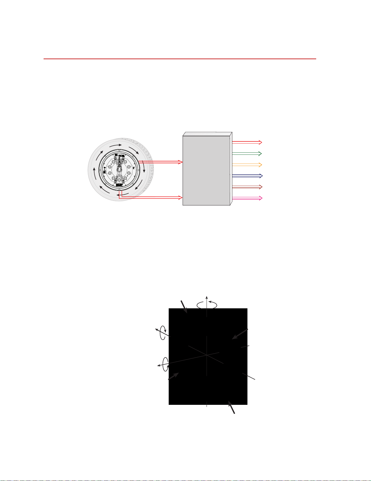
Coordinate System
In the transducer, independent strain gage bridges measure forces and moments
about three orthogonal axes. The signals are amplified to reduce the signal-tonoise ratio. An encoder signal indicates angular position, which is used to
convert raw force and moment data from the rotating transducer to a vehiclebased coordinate system. The force and moment and encoder information is sent
to the transducer interface (TI).
The TI performs cross talk compensation and converts the rotating force and
moment data to a vehicle coordinate system. The result is six forces and moments
that are measured at the spindle: Fx, Fy, Fz, Mx, My, and Mz. A seventh
(angular) output is available for tire uniformity information, angular position, or
to determine wheel speed (depending on the data acquisition configuration).
The coordinate system shown below was originally loaded into the TI settings by
MTS. It uses the right-hand rule.
Hardware Overview
22
SWIFT 50 GLP Sensors
Page 23

Coordinate System
The SWIFT coordinate system is transducer-based, with the origin located at the
center of the transducer. Positive loads are defined as applied to the outer ring of
the transducer.
• Vertical force (Fz) is positive up
• Lateral force (Fy) is positive out of the vehicle
• Longitudinal force (Fx) is positive out of the transducer
You can change to the MTS Model 329 Road Simulator convention (lateral load
into the vehicle is always positive) or to any coordinate system by changing the
polarities in the calibration file. For instructions on how to change the coordinate
system polarities, see the chapter, “Setting up the Transducer Interface”.
SWIFT 50 GLP Sensors Hardware Overview
23
Page 24

Specifications
Specifications
SWIFT 50 GLP Transducer Performance (part 1 of 2)
Parameter Specification
Use
SWIFT 50 GLP S (stainless steel) for
SWIFT 50 GLP T (titanium) for
Maximum usable rpm
Maximum speed
Fits rim size (usable range)
Maximum hub bolt circle diameter
accommodates M22 studs
Input voltage required (mini TI)
Input power required (mini TI)
Output voltage ± full scale calibrated load
SAE J267
Rated load capacity
Bending moment
Full scale calibrated ranges#
Longitudinal force (Fx)
Lateral force range (Fy)
Vertical force range (Fz)
Overturning moment (Mx)
Driving/braking moment (My)
Steering moment (Mz)
Resolution (analog system)
Noise level (peak-to-peak 0-500 Hz)
Performance accuracy
Nonlinearity
Hysteresis
Modulation**
Cross talk
††
‡
§
high fatigue life, durability
low weight, high sensitivity
2,200
200 kph (125 mph)
22.5–24.5 inch
*
335 mm (13.189 in)
10–28 V DC
8 W maximum (6 W typical)
†
±10 V
Stainless SteelTitanium
64.50 kN (14,500 lbf)44.48 kN (10,000 lbf)
55.8 kN•m (494,075 lbf•in)38.5 kN•m (340,740 lbf•in)
±220 kN (±49,458 lbf) ±150 kN (±33,721 lbf)
±100 kN (±22,481 lbf) ±60 kN (±13,489 lbf)
±220 kN (±49,458 lbf) 150 kN (±33,721 lbf)
±50 kN•m (±442,537 lbf•in) ±37 kN•m (±327,478 lbf•in)
±50 kN•m (±442,537 lbf•in) ±40 kN•m (±354,030 lbf•in)
±50 kN•m (±442,537 lbf•in) ±37 kN•m (±327,478 lbf•in)
Infinite
40 N (9.0 lbf) 30 N (6.7 lbf)
1.0% full scale
0.75% full scale
≤5.0% reading
1.5% full scale
Hardware Overview
24
SWIFT 50 GLP Sensors
Page 25

SWIFT 50 GLP Transducer Performance (part 2 of 2)
Parameter Specification
Maximum operating temperature
Specifications
Low level amplifiers
Transducer interface
* Contact MTS for other rim sizes.Larger diameter rims can be used, provided that overall clearance from
brake calipers and suspension components is maintained.
† Load impedance >1 k
‡ Half axle rated capacity per SAE 267.
§ Seen on the transducer for 100,000 cycles.
# The actual calibrated range may be different based on individual customer requirements. Consult the
calibration range sheet that accompanies each transducer for the correct calibration range.
** Typical value on most steel rims. Stainless steel rims typically have slightly higher modulation, but at a
lower added weight.
†† Each SWIFT sensor is calibrated on an MTS calibration machine. MTS provides complete documentation
of calibration values for each SWIFT unit. Unique calibration values are stored electronicall y and
transferred to the transducer interface unit (TI box) shipped with each SWIFT 50.
Ω; 0.01 µF (maximum) load capacitance.
70°C (158°F)
50°C (122°F)
SWIFT 50 GLP Sensors Hardware Overview
25
Page 26

Calibration
Calibration
Each transducer is calibrated by MTS before shipment. The transducer and TI
may be returned to MTS for repair and recalibration as required.
Calibration is performed at MTS on a special fixture that is capable of applying
multiple loads to the transducer. During calibration, raw signals are measured.
The calibration gains and cross talk compensation values are computed from this
raw data. These gains are recorded in a calibration file.
A unique calibration file is supplied for each transducer. The serial number of the
TI associated with the transducer is listed at the top of the calibration file. A label
with the serial number of the TI box (and the SWIFT sensor with which it was
originally calibrated) is attached to the back of each TI box.
The calibration file is loaded into the TI non-volatile RAM by MTS before the
transducer is shipped. A copy of the file is also provided on a diskette.
MTS verifies the calibration by applying loads to the transducer, measuring the
main outputs and checking for accuracy. Final calibration reports are provided
with each transducer.
Shunt calibration Shunt calibration information can be found in the SWIFT
Interface product manual, part number 100-214-316.
®
Mini Transducer
Hardware Overview
26
SWIFT 50 GLP Sensors
Page 27

Interfacing with RPC
The SWIFT sensor is directly compatible with the MTS Remote Parameter
Control (RPC) simulation software. The SWIFT system produces outputs that
directly correspond to the uncoupled spindle forces that the MTS Model 329
Road Simulator applies to the vehicle. Traditional instrumentation techniques
provide coupled suspension loads data. Using the SWIFT sensor, the RPC
simulation software needs to apply less correction to obtain the road simulator
drive signals. Fewer iterations are required to recreate the measured loads.
You must ensure that the full scale value for your data recorder and the MTS
electronics match. MTS electronics are typically set at ±10 V full scale, while
some data recorders are ±5 V full scale.
The SWIFT sensor is calibrated for ±10 V full scale. T o recompute the TI gains
for ±5 V full scale, a verification pass must be run or the calibration will not be
traceable. Upon special request, MTS can evaluate and may provide calibration
for ±5 V or other full scale voltages.
Interfacing with RPC
SWIFT 50 GLP Sensors Hardware Overview
27
Page 28

Interfacing with RPC
Hardware Overview
28
SWIFT 50 GLP Sensors
Page 29

Installation
Contents Hazard Icons 30
The SWIFT sensor can be installed on a vehicle at the test track or on an MTS
Series 329 Road Simulator in the test laboratory.
Road and Track Vehicles 31
Attaching SWIFT Components to the Vehicle 36
Attaching SWIFT Components to the Fixturing 48
SWIFT 50 GLP Sensors Installation
29
Page 30

Hazard Icons
Hazard Icons
Read, understand, and
follow the instructions
in the manual
The following hazard icon is part of the label affixed to the side of the SWIFT 50
GLP Sensor.
30
Installation
SWIFT 50 GLP Sensors
Page 31

Road and Track Vehicles
Road and Track Vehicles
Equipment required This procedure requires two people. T o install the SWIFT 50 GLPS or SWIFT 50
GLPT sensor, you will need the following equipment:
• Spindle adapter spacers (see next figure)
• Modified rim (see next figure)
• Anti-rotate assembly (including customer-supplied mounting arm)
• Small set of metric hex-head wrenches
• Tube bender for the restraint tube
• Tube cutter
• Metric socket head drive set (up to 14 mm) with extension
• Molykote g-n paste, 2.8 oz. tube (MTS part number 011-010-217)
• Nikal based anti-galling compound (MTS part number 011-354-902)
• Transducer mounting bolts (per transducer)
For dual rims
16 size M16 X 1.5 mm
8 size M10 X 1.5 mm
4 size M5 X 0.5 mm
lug nuts and shim washers
For front rims
16 size M16 X 1.5 mm
8 size M10 X 1.5 mm
4 size M5 X 0.5 mm
lug nuts and shim washers
• For dual rims
Slip ring extension assembly
Four size M12 X 1.75 mm X 30 mm long bolts
• Slip ring assembly fasteners
Four size M8 X 1.25 mm X 20 mm long bolts
• Torque wrenches, capable of the following ranges:
2.3–23 N•m (20–200 lbf•in)
24–74 N•m (18–55 lbf•ft),
SWIFT 50 GLP Sensors Installation
31
Page 32

Road and Track Vehicles
Slip Ring
Bracket
(with encoder)
Lug Nuts and
Shim Washers (10)
Spindle Adapter
Spacer
Transducer
Modified
Wheel Rim
(front wheel)
S50-008
Spacer-to-Transducer
Fasteners
Rim-to-Transducer
Assembly Fasteners
Modified
Wheel Rim
(dual wheel)
Transducer
Spindle
Adapter
Spacer
Lug Nuts and
Shim Washers (10)
S50-013
Slip Ring
Extension
Bracket
Slip Ring
Bracket
(with encoder)
Spacer-to-Transducer
Fasteners
Rim-to-Transducer
Assembly Fasteners
203–815 N•m (150-600 lbf•ft);
108–325 N•m (80–240 lbf •ft)
93 N•m (69 lbf•ft)
• Cables (transducer and BNC, plus customer-supplied from transducer
interface to data recorder)
• Tie wr aps
• Data recorder
• Power supply–12 V DC (optionally 24 V DC; for example, a truck battery)
Installation Components (Test Track–Front)
Installation Components (Test Track–Duals)
Installation
32
SWIFT 50 GLP Sensors
Page 33

Road and Track Vehicles
Importance of bolts Bolts provide exceptional clamp force at the transducer to rim/spindle interface.
• Bolts on the inner hub secure the hub adapter to the SWIFT sensor.
• Bolts on the outer ring secure the SWIFT sensor to the wheel rim (or road
simulator spindle adapter).
Note Make sure all bolts are in place and fully torqued during all tests. Correct
use of bolts reduces the safety hazard and ensures optimal transducer
performance.
SWIFT 50 GLP Sensors Installation
33
Page 34

Road and Track Vehicles
CAUTION
CAUTION
CAUTION
WARNING
Before you begin Observe the following safety conditions while you are attaching the SWIFT
sensor and components to the vehicle.
Do not pressure-wash the transducer or clean it with solvents.
Pressure-washing the transducer or cleaning it with solvents can damage it
or degrade the silastic seal and may void the warranty.
Using strong cleaners or solvents can damage the RTV seal and may void
the warranty .
Use only a soft sponge or brush with non-metal bristles and a gentle detergent
(such as dish soap) to wash the transducer.
Do not use high-pressure air to clean debris from around the transducer
connectors.
High-pressure air can damage the silastic seals and may void the warranty.
Use a brush with fine, non-metal bristles and low air-pressure [0.07 MPa (10 psi)]
to clean debris from around the transducer connectors.
Do not lay the wheel down on top of the transducer without proper padding.
If the wheel is laid down with the transducer under it, the transducer could
be scratched and the connectors damaged.
Always hold the wheel upright when the transducer is attached to it. If needed,
have another person hold the wheel upright while you tighten the bolts, if laying
the wheel down cannot be avoided, place the wheel on a layer of foam or a pad to
protect the connectors.
Do not under-torque the lug nuts.
Lug nuts that are not properly tightened can become loose during testing.
Loss of a wheel can cause damage to the test vehicle and transducer and
result in serious injury, death, or property damage.
34
Installation
Always tighten the lug nuts to the torque rating recommended for the vehicle/
wheel. Recheck the torque daily and/or before each testing session.
SWIFT 50 GLP Sensors
Page 35

Road and Track Vehicles
CAUTION
CAUTION
Do not drop the slip-ring bracket.
Dropping the slip-ring bracket can damage the slip ring or a connector.
Always use care when you handle the slip-ring bracket.
Do not allow the mounting arm or anti-rotate arm to bump against any
portion of the wheel or wheel well.
Any jarring of the mounting arm or anti-rotate arm will damage the slip ring
and/or the encoder.
Position the mounting arm and anti-rotate assembly so that full suspension travel
will not cause interference with the wheel well or any other part of the vehicle.
SWIFT 50 GLP Sensors Installation
35
Page 36

Road and Track Vehicles
Attaching SWIFT Components to the Vehicle
SWIFT 50 GLP Fasteners
Front Rim Dual Rims
M16 X 1.5 mm
M10 X 1.5 mm
M5 X 0.8 mm
MTS modified lug nuts an d sh im washers
* The length of these fasteners is dependant on the thickness of the
rim flange. The fastener length must ensure a minimum thread
engagement of 37 mm (1.46 in) but must not exceed 43 mm (1.69
in).
† The length of these fasteners is dependant on the thickness of the
rim flange. The fastener length must ensure a minimum thread
engagement of 28 mm (1.10 in) but must not exceed 34 mm (1.33
in).
‡ These fasteners secure the spindle adapter spacer to the
transducer. The length of these fasteners is dependant on the
thickness of the spindle adapter spacer which is a function of the
customer wheel geometry.
§ The standard lug nuts provided have a thread size of M22 X 1.50
mm. Other thread sizes can be ordered at customer request.
*
†
‡
M16 X 1.5 mm*
M10 X 1.5 mm
M5 X 0.8 mm
‡
§
†
Material required:
• Molykote g-n paste (MTS part number 011-010-217).
36
Procedure 1. Remove the current wheel from the test vehicle.
Installation
• Nikal based anti-galling compound (MTS part number 011-354-902)
2. Clean all surfaces of the vehicle tire(s) and the modified rim(s). It is critical
that all surfaces be free of stones, burrs, and grease. Use a mild detergent
such as dish soap.
Important It is imperative that the mounting surfaces of the transducer be
protected from getting scratched. Any wheel components and work
surfaces that might come in contact with the transducer must be
clean, smooth, and free of debris
Mount the tire(s) on the modified rim(s).
3. Wipe the unpainted mating surfaces of the modified rim, the spindle adapter
spacer and the transducer with a clean dry cloth.
SWIFT 50 GLP Sensors
Page 37

Road and Track Vehicles
4. Attach the spindle adapter spacer to the rim side of the transducer (see the
next figure) using the four M5 fasteners provided (see the previous table).
Ensure the pilot surface of the spindle adapter spacer is facing the
transducer.
Lubricate the threads and under the head of each fastener with Molykote g-n
paste and torque to 6.5 N•m (4.8 lbf-ft).
SWIFT 50 GLP Sensors Installation
37
Page 38

Road and Track Vehicles
Dual Rim
Front Rim
Hub Side
Connector Side
S50-006
Rim and Hub Mount Side
1 through 10 = M22
(modified lug nuts)
A through H = M10 bolts
1 through 16 = M16 bolts
Spindle
Adapter
Spacer
Transducer
Transducer
Hub Side
Spindle
Adapter
Spacer
M5 Threaded
Holes (4)
Modified
Lug Nuts
Modified
Lug Nuts
5. Attach the transducer to the modified wheel rim using the fasteners provided
(see the previous table). Hand tighten the bolts.
If environmental conditions warrant, coat each fastener with Birchwood
Casey Sheath RB1 rust preventative (or equivalent).
Lubricate the threads and under the head of each fastener with Molykote g-n
paste.
Bolt Torque Sequence
38
Installation
SWIFT 50 GLP Sensors
Page 39

Road and Track Vehicles
6. Tighten the M10 mounting bolts.
A. Following the sequence shown in the previous figure, torq ue the eigh t
M10 bolts (A through H) to the value for the first increment shown in
the following table.
B. Repeat Step 6A for the second increment.
C. Repeat Step 6A for the final torque.
7. Tighten the M16 mounting bolts.
A. Following the sequence shown in the previous figure, torque the
sixteen M16 bolts (1 through 16) to the value for the first increment
shown in the following table.
B. Repeat Step 7A for the second increment.
C. Repeat Step 7A for the final torque.
Note To minimize negative clamping effects, you must torque the bolts in the
sequence shown.
Bolt Size
Torque Increment M10 M16
1st Increment
2nd Increment
Final Torque
24 N•m (18 lbf•ft) 108 N•m (80 lbf•ft)
48 N•m (36 lbf•ft) 317 N•m (160 lbf•ft)
74 N•m (55 lbf•ft) 325 N•m (240 lbf•ft)
SWIFT 50 GLP Sensors Installation
39
Page 40

Road and Track Vehicles
For front or steering axles,
anti-rotate arm must be
mounted to a part of the
unsprung suspension that
steers with the tire, such as
the brake caliper.
Front Wheel Slip Ring and Anti-Rotate Assembly
Anti-Rotate Bracket
(customer supplied)
Anti-Rotate
Assembly
Slip Ring
Slip-Ring
Bracket
S50-44
Transducer
Cable
Conduit
Bracket
Attaching SWIFT and Wheel Assembly to the Vehicle
1. Before installing the SWIFT and wheel assembly, attach the anti-rotate
bracket to the vehicle.
Since the bracket is unique to each vehicle the anti-rotate bracket must be
provided by the customer. The following are guidelines for manufacturing
and locating the bracket. See the next two figures.
• The bracket must be stiff, preferably steel or stiff stainless steel tubing,
so as not to move or rotate when connected to an unsprung mass or
spindle which will allow the slip ring assembly to move with the tire as
the vehicle is moving or testing.
• The bracket must be positioned so as not to hit the fender at the
extreme end of the suspension travel.
• The bracket must maintain a minimum clearance from the tire so as not
to hit the tire when it is loaded and rotating.
Installation
40
SWIFT 50 GLP Sensors
Page 41
Road and Track Vehicles
CAUTION
2. Attach the wheel/transducer to the test vehicle.
Installing the lug bolts directly against the transducer face, without the antigalling compound and the shim washers, can cause galling of the
transducer face.
Galling of the transducer face can result in uneven torquing (and possible
over-torquing) of the lug bolts.
To prevent galling, always use the shim washers provided. Always lubricate the
bolts and shim washers as described below.
Lubricate the lug bolt threads, under the bolt head, and both faces of the
shim washers with the Nikal based anti-galling compound.
Tighten the lug nuts in 203 N•m (150 lbf•ft) increments, in the sequence
shown in the next figure to the torque rating recommended for the wheel.
SWIFT 50 GLP Sensors Installation
41
Page 42

Road and Track Vehicles
54
36
9 7
8 10
2
1
S50-41
Modified
Lug Nuts (10)
Transducer
Important Do not exceed a torque of 815 N•m (600 lbf•ft).
3. If necessary, assemble the cable conduit brackets and hinge base with antirotate tube onto the slip ring. See the next figure.
Note Typically this step is only required for new slip rings. After the assembly
is complete, there should be no need to disassemble it except if a
component becomes damaged.
A. Connect the cable to the slip ring.
B. Wrap the slip-ring connector and cable connector with butyl rubber
shrink tape (MTS part number 100-175-781 or equivalent).
Cut approximately 150 mm (6 in) of tape from the roll.
Remove the backing from the tape.
Stretch the tape until it is approximately 1/2 of its original width.
Begin by putting two wraps of tape tightly around the slip ring
connector and cable connector.
Continue wrapping up the connector and cable approximately 150 mm
(6 in). Overlap the tape by approximately 1/2 of its width.
42
Installation
SWIFT 50 GLP Sensors
Page 43

Road and Track Vehicles
2
C. Install the cable conduit bracket onto the slip ring and secure the left
side with the four M5 X 0.8 mm fasteners.
Lubricate the fasteners with Molykote g-n paste and torque to 6.5 N•m
(56 lbf•in).
D. Align the hinge base to the holes on the right side of the cond uit cable
bracket and slip ring. Rotate the hinge coupling and tube 90° to access
the top hole.
Secure the hinge base with the four M5 X 0.8 mm fasteners.
Lubricate the fasteners with Molykote g-n paste and torque to 6.5 N•m
(56 lbf•in).
E. Rotate the anti-rotate tu be parallel to the cable conduit bracket.
Secure the cable to the cable conduit bracket using tie-wraps through
the holes in the bracket and two M5 x 0.8 mm fasteners.
Use tie-wraps to also secure the cable to the anti-rotate tube.
4. For front rim configurations (see the next figure): Attach the slip-ring
bracket with the slip ring, conduit bracket, and restraint tube to the
transducer.
A. The slip-ring bracket fit s over the 9-pin connectors on the front of the
transducer at the locations labeled Board A and Board B. The slip-ring
bracket is similarly labeled to prevent connecting it the wrong way.
SWIFT 50 GLP Sensors Installation
43
Page 44

Road and Track Vehicles
For front or steering axles,
anti-rotate arm must be
mounted to a part of the
unsprung suspension that
steers with the tire, such as
the brake caliper.
Front Wheel Slip Ring and Anti-Rotate Assembly
Anti-Rotate Bracket
(customer supplied)
Anti-Rotate
Assembly
Slip Ring
Slip-Ring
Bracket
S50-44
Transducer
Cable
Conduit
Bracket
Note Use care when installing the slip-ring bracket. The 9-pin connectors are
keyed. The slip-ring bracket should be fitted on straight (without bending
or angling it) to make sure it engages all four connectors simultaneously
and evenly.
B. Lubricate the threads and under the bolt heads of the four M8 X 1.25
mm bolts with Molykote g-n paste. Insert them through the mounting
hole in the slip-ring bracket and thread them into the transducer . T orque
each to 27 N•m (20 lbf•ft).
C. Make sure that the covers on the shunt connectors are in place and
secure.
Press the covers over the shunt connector. Secure the covers by
tightening the two SST 10-32 UNF screws (one for each cover), using
an M4 or 5/32 inch hex key wrench, to 3.8 N•m (2.8 ft-lbf).
Installation
44
5. For dual rim configurations (see the next figure): Attach the extension
assembly and slip-ring bracket with slip ring to the transducer.
A. Thread the standoffs, with the M12 threaded studs, into the four M12
threaded holes in the face of the transducer.
Lubricate the threads on each threaded stud with Molykote g-n paste
and torque to 93 N•m (69 lbf•ft).
B. Attach the four extension brackets to the top plate using the M5 X 10
mm long fasteners provided (2 fasteners each).
Orient the short side of the dovetail on the connector toward the center
of the top plate.
Lubricate each fastener with Molykote g-n paste and torque each to 6.5
N•m (58 lbf•in).
SWIFT 50 GLP Sensors
Page 45

Road and Track Vehicles
Standoffs (4)
Top Plate
Slip-Ring
Bracket
M12 Threaded
Studs (4)
Extension
Brackets (4)
S50-40
M12 Bolts (4)
and Washers
Anti-rotate
Hinge
Assembly
Tube
Cable
Cable
Conduit
Bracket
Slip
Ring
Hinge
M8 Bolts (4)
C. Place the top plate, with extensions attached, over the standoffs.
Orient the top plate such that the Board A extension (see the labeling
on the top plate) is aligned with the Board A connector on the
transducer.
Note Use care when installing the top plate and extensions. The 9-pin
connectors are keyed. The top plate and extensio ns should be fitted on
straight (without bending or angling it) to make sure they engage the four
connectors simultaneously and evenly.
D. Secure the top plate to the st andoffs using the four M12 bolts and
washers.
Lubricate the threads with Molykote g-n paste and torque to 93 N•m
(69 lbf•ft).
SWIFT 50 GLP Sensors Installation
45
Page 46

Road and Track Vehicles
E. Install the slip-ring bracket with the slip ring, conduit bracket, and
restraint tube.
Slide the restraint tube through the hole in the anti-rotate bracket
(installed earlier) as far as necessary to align the slip-ring bracket to the
connectors on the top plate.
The slip-ring bracket fits over the 9-pin connectors on the top plate at
the locations labeled Board A and Board B. The slip-ring bracket is
similarly labeled to prevent connecting it the wrong way.
46
Installation
SWIFT 50 GLP Sensors
Page 47

Road and Track Vehicles
Note Use care when installing the slip-ring bracket. The 9-pin connectors are
keyed. The slip-ring bracket should be fitted on straight (without bending
or angling it) to make sure it engages both connectors simultaneously
and evenly.
F. Lubricate the threads and under the bolt heads of the four M8 X 1.25
mm bolts with Molykote g-n paste. Insert them through the mounting
holes in the slip-ring bracket and thread them into the transducer.
Torque them to 27 N•m (20 lbf•ft).
G. Make sure that the covers on the shunt connectors are in place and
secure.
Press the covers over the shunt connector. Secure the covers by
tightening the two SST 10-32 UNF screws (one for each cover), using
an M4 or 5/32 inch hex key wrench, to 3.8 N•m (2.8 ft-lbf).
6. Secure the cable along the restraint tube, as necessary, to prevent it from
rubbing against the tire.
7. Secure the cable along the remainder of its length so that it will not become
damaged during data collection. (For example, tape it to the fender or
frame.)
Important Be sure to leave enough slack in the cable to allow for the full
range of wheel travel (jounce and steer) so the cable does not
become stretched or damaged during testing.
8. Install the Transducer Interface.
At this point, you should install the transducer interface, verify the quality of
the zero algorithm, and set up data collection. Refer to the SWIFT
®
Mini
Transducer Interface product manual, part number 100-214-316.
SWIFT 50 GLP Sensors Installation
47
Page 48

Road and Track Vehicles
Attaching SWIFT Components to the Fixturing
Note Install the transducer in so that the orientation labeling is consistent with
the reference orientation. In most cases, this means installing it so the
labels are upright. If an additional angle correction is required after
installation, you will need to measure the angle from zero, and then enter
a new offset value for the AngleOffset in the TI calibration file (see
SWIFT® Mini Transducer Interface product manual, part number
100-214-316.).
SWIFT 50 GLP Fasteners
Front Rim Dual Rims
M16 X 1.5 mm
M10 X 1.5 mm
M5 X 0.8 mm
MTS modified lug nuts an d sh im washers
* The length of these fasteners is dependant on the thickness of the
rim flange. The fastener length must ensure a minimum thread
engagement of 37 mm (1.46 in) but must not exceed 43 mm (1.69
in).
† The length of these fasteners is dependant on the thickness of the
rim flange. The fastener length must ensure a minimum thread
engagement of 28 mm (1.10 in) but must not exceed 34 mm (1.33
in).
‡ These fasteners secure the spindle adapter spacer to the
transducer. The length of these fasteners is dependant on the
thickness of the spindle adapter spacer which is a function of the
customer wheel geometry.
§ The standard lug nuts provided have a thread size of M22 X 1.50
mm. Other thread sizes can be ordered at customer request.
*
†
‡
M16 X 1.5 mm*
M10 X 1.5 mm
M5 X 0.8 mm
‡
§
Material required • Molykote g-n paste (MTS part number 011-010-217).
• Nikal based anti-galling compound (MTS part number 011-354-902)
†
48
Installation
1. Clean all surfaces with a mild detergent such as dish soap. It is critical that
all surfaces be free of stones, burrs, and grease.
2. Attach the spindle adapter spacer to the rim side of the transducer (see the
next figure) using the four M5 fasteners provided (see the previous table).
Ensure the pilot surface of the spindle adapter spacer is facing the
transducer.
Lubricate the threads and under the head of each fastener with Molykote g-n
paste and torque to 6.5 N•m (4.8 lbf-ft).
SWIFT 50 GLP Sensors
Page 49

Road and Track Vehicles
CAUTION
3. Tighten the M10 mounting bolts.
A. Following the sequence shown in the previous figure, torq ue the eigh t
M10 bolts (A through H) to the value for the first increment shown in
the following table.
B. Repeat Step 3A for the second increment.
C. Repeat Step 3A for the final torque.
4. Tighten the M16 mounting bolts.
A. Following the sequence shown in the previous figure, torque the
sixteen M16 bolts (1 through 16) to the value for the first increment
shown in the following table.
B. Repeat Step 4A for the second increment.
C. Repeat Step 4A for the final torque.
Note To minimize negative clamping effects, you must torque the bolts in the
sequence shown.
Bolt Size
Torque Increment M10 M16
1st Increment
2nd Increment
24 N•m (18 lbf•ft) 108 N•m (80 lbf•ft)
48 N•m (36 lbf•ft) 317 N•m (160
lbf•ft)
Final Torque
74 N•m (55 lbf•ft) 325 N•m (240
lbf•ft)
5. Bolt the transducer/hub adapter to the road simulator fixture using the
modified lug nuts and shim washers provided.
Installing the lug bolts directly against the transducer face, without the antigalling compound and the shim washers, can cause galling of the
transducer face.
Galling of the transducer face can result in uneven torquing (and possible
over-torquing) of the lug bolts.
To prevent galling, always use the shim washers provided. Always lubricate the
bolts and shim washers as described below.
Lubricate the lug bolt threads, under the bolt head, and both faces of the
shim washers with the Nikal based anti-galling compound.
(Refer to the documentation provided with the road simulator.)
Tighten the lug nuts in 203 N•m (150 lbf•ft) increments, in the sequence
shown in the next figure to the torque rating recommended for the wheel.
Important Do not exceed a torque of 815 N•m (600 lbf•ft).
SWIFT 50 GLP Sensors Installation
49
Page 50

Road and Track Vehicles
Connector Side
S50-47
329 Simulator and Hub Mount Side
1 through 10 = M22
(modified lug nuts)
A through H = M10 bolts
1 through 16 = M16 bolts
M5 Threaded
Holes (4)
6. Repeat steps 1 through 5 for each corner.
7. Install the vehicle on the road simulator.
Refer to the instructions in your road simulator operation manual.
8. Attach the connector housing (or the slip ring bracket and slip ring) to each
transducer.
9. Attach the appropriate cables from the connector housing or one cable from
the slip ring to the TI or data acquisition.
A. Connect the cable from the Load connector on the connector housing,
B. If used, connect the cable from the Accel connector on the connector
Bolt Torque Sequence
or from the slip-ring connector, to the transducer connector on the slipring daughter board of the TI box(es).
housing to your data acquisition device.
Installation
50
SWIFT 50 GLP Sensors
Page 51

Road and Track Vehicles
C. Connect the cables from the Shunt A and Shunt B connectors on the
connector housing or the slip-ring bracket to the Shunt A and Shunt B
connectors on the TI box(es)
D. Secure the cables to the lateral strut of the road simulator so that it will
not become damaged during testing.
Be sure to leave enough slack for the full range of movement of the
simulation fixture.
10. Connect the power supply (12 V DC or optiona l 24 V DC) to the TI.
You might need to first convert from 120 or 240 V AC to 12 V DC or 24 V
DC.
11. Connect the data cables from the TI to the data recorder or your test control
system. There is one cable per channel of data from the TI to the data
recorder.
SWIFT 50 GLP Sensors Installation
51
Page 52

Road and Track Vehicles
52
Installation
SWIFT 50 GLP Sensors
Page 53

Analyzing SWIFT Data
Overview This chapter contains examples of data collected from SWIFT installations, and
explains how the data can be analyzed.
Contents The Data 54
Fx Data (Longitudinal Force) 55
Fz Data (Vertical Force) 57
Mx Data (Overturning Moment) 58
My Data (Brake Moment) 61
Acceleration and Braking Events Example 63
Slalom Curve Driving Example 65
SWIFT 50 GLP Sensors Analyzing SWIFT Data
53
Page 54

The Data
The Data
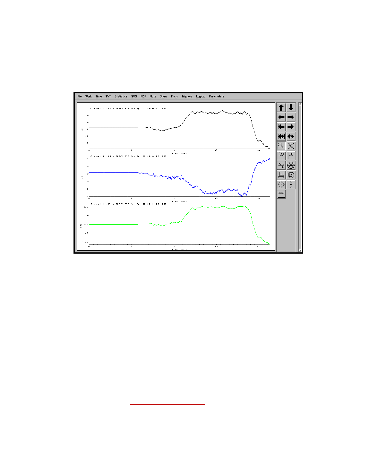
The following figure shows handling data taken on a flat, winding surface, using
a SWIFT sensor and SOMAT software. The driving speed was between 30 and
100 kph (18–62 mph).
Analyzing SWIFT Data
54
SWIFT 50 GLP Sensors
Page 55

Fx Data (Longitudinal Force)
Mz+
Distance
Fx+
S50-016
Direction
of Motion
Distance
Fx+
S50-015
Mz+
Direction
of Motion
Fx Data (Longitudinal Force)
This figure shows the Fx (longitudinal force) data.
• The offset in Fx after zeroing the SWIFT sensor is due to frictional force
and rolling resistance on a flat road.
• There is a strong similarity between Fx and Mz, due to the SWIFT sensor
measurement characteristics. That is, the SWIFT sensor measures at the
transducer centerline. As a result, any Fx load results in an additional Mz
output:
Mz due to Fx loading = Fx load x Distance
SWIFT 50 GLP Sensors Analyzing SWIFT Data
55
Page 56

Fx Data (Longitudinal Force)
Friction/Rolling
resistance Offset
Mz Offset due to
Fx=28Nm
The following figure illustrates the relationship between Fx and Mz, for this test
case, which had a 170 mm (6.7 inch) offset from the tire centerline to the SWIFT
sensor centerline:
Fx = 165 N observed
Distance = 170 mm
Mz = Fx x Distance = 165 N x 170 mm = 28 N•m
Analyzing SWIFT Data
56
SWIFT 50 GLP Sensors
Page 57

Fz Data (Vertical Force)
The offset force in the Z direction is the combined weight of the car, equipment,
and driver at that corner.
5.2 kN = 530 kg (force) = 1169 lb for this vehicle at static loading.
Fz Data (Vertical Force)
SWIFT 50 GLP Sensors Analyzing SWIFT Data
57
Page 58

Mx Data (Overturning Moment)
S50-018
Fz
Distance Y
Distance Z
S50-017
Fz
Distance Z
Distance Y
Mx
Mx Data (Overturning Moment)
The moment Mx is the resultant of the forces Fz and Fy, and their respective
distances to the center of the SWIFT sensor.
After zeroing the SWIFT sensor, with the wheel off the ground, there will always
be a small moment Mx present. This is due to the offset of the tire assembly
center of gravity from the SWIFT sensor centerline.
Analyzing SWIFT Data
58
SWIFT 50 GLP Sensors
Page 59
Mx Data (Overturning Moment)
Fy
Fz
Mx
Channel 4 Mx Data The following figure shows the relationship between Mx, Fz, and Fy, during a
cornering event. Fz decreases as the vertical force is shifted to the opposite
wheel. Fy, the lateral force, increases to prevent side slip resulting in an increase
in the overturning moment, Mx.
1
Mx = Fy x Distance Z +
Fz x Distance Y
After zeroing the SWIFT sensor with the wheel off the ground, a moment Mx
will still be present, as the following figure shows.
1 Actual polarities depend upon how the polarity for each signal is set in the
TI.
(See “OutputPolarities” in, “Setting up the Transducer Interface.”)
SWIFT 50 GLP Sensors Analyzing SWIFT Data
59
Page 60

Mx Data (Overturning Moment)
Fz
CG
x
Fz
CG
x
Mx offset with
the wheel off
the ground
Mx offset with
the wheel off
the ground
Mx (wheel off ground) = Fz (active weight of the tire and rim outside the
transducer) x Distance (CG to SWIFT sensor centerline)
Analyzing SWIFT Data
60
SWIFT 50 GLP Sensors
Page 61

My Data (Brake Moment)
S50-020
My
Distance Y
Distance Z
My
Fx
Distance Z
S50-019
Fx
My
My
Distance Y
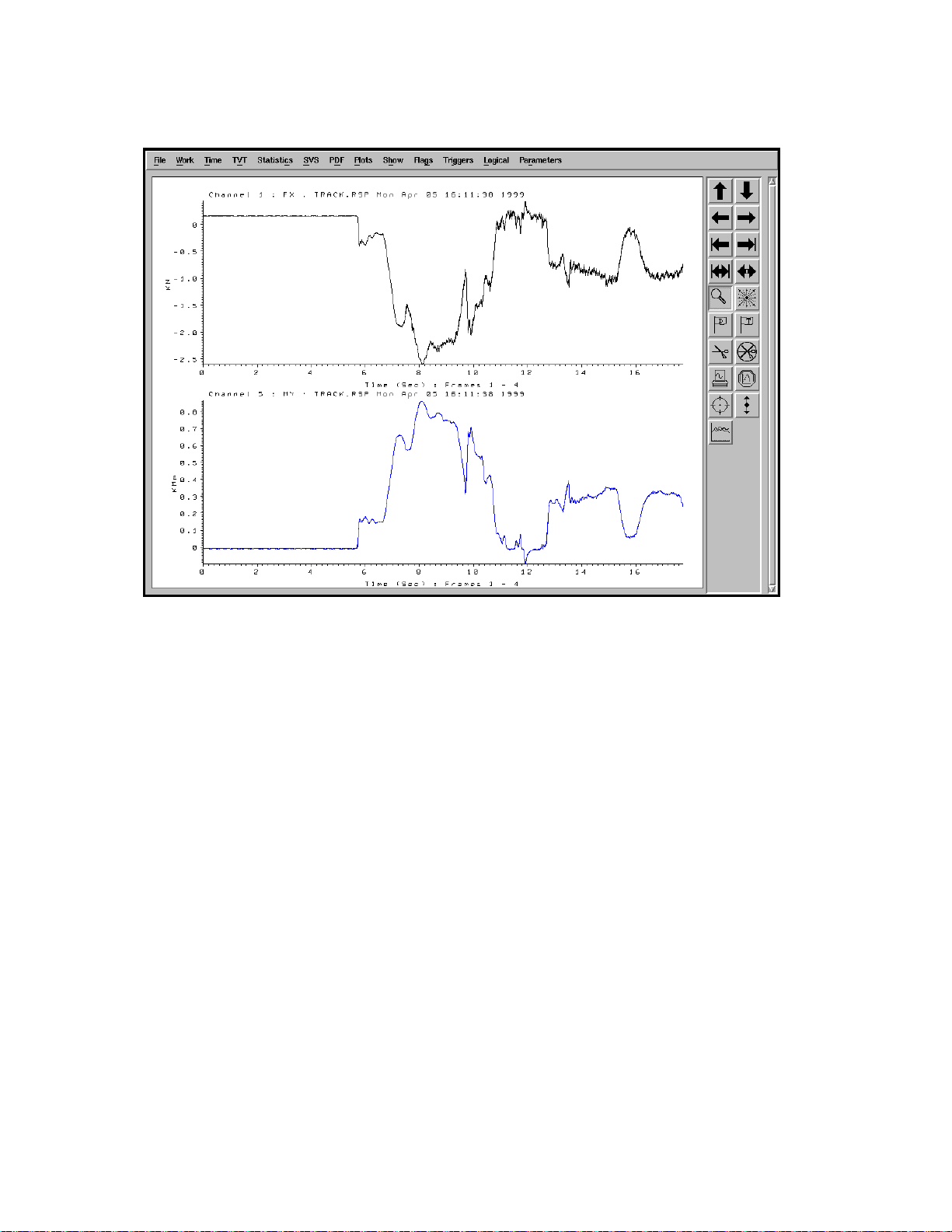
The moment My should show strong similarities with the force Fx and is
calculated by the SWIFT sensor using the distance Z.
My Data (Brake Moment)
∝ Fx x Distance Z
My
SWIFT 50 GLP Sensors Analyzing SWIFT Data
61
Page 62
My Data (Brake Moment)
The relationship between Fx and My is shown in the following time history plot:
Analyzing SWIFT Data
62
SWIFT 50 GLP Sensors
Page 63

Acceleration and Braking Events Example
Acceleration and Braking Events
-2000
-1500
-1000
-500
0
500
1000
1500
2000
02468101214
time in seconds
Output - Lbs
-15000
-10000
-5000
0
5000
10000
15000
Output- In-Lbs
Fx (trac t i ve force) - Lbs
Fy ( l ateral force) - Lbs
Fz (nor m a l force) - Lbs
n
My (wheel torque) - In-Lbs
Mz (aligni ng torque) -In-Lbs
Acceleration and Braking Events Example
Shown below is actual road data taken with the MTS SWIFT Sensor, located at
the front passenger side of a mid-size passenger vehicle. Data shown is postprocessed to translate the forces and moments from the center of the transducer to
the center of the tire.
Mx (overturning mom en t) - I
The outputs from this acceleration and braking event are shown above. It should
be noted that output fluctuations are primarily due to actual road surface
irregularities.
Time 0 to 3.8 seconds: The car is at rest, with the brakes applied; no motion. The
vertical force of the vehicle on this wheel is noted as slightly over 1000 lb.
Time 3.8 to 4.3 seconds: The brake pedal is released with the transmission
engaged. Note the forces generated from th e slight drive torque of the idle in this
automatic transmission vehicle.
Time 4.3 to 6 seconds: Acceleration begins and transient forces and moments
are shown.
Fx: Slightly less than 1000 lb of tractive force is reacting at the tire patch.
Fy: Minimal Fy force is noted as the steering angle is maintained roughly
straight. Slight variations are noted with steering angle and vehicle suspension
toe-in geometry effects.
Fz: The normal force is the result of weight transfer from the front wheel to the
rear of the vehicle, and the anti-squat forces present in this front wheel drive
vehicle.
Mx: The Mx output noted is corrected to give the overturning moment at the
center of the tire. Minimal Mx moments are generated during these acceleration
and braking events.
SWIFT 50 GLP Sensors Analyzing SWIFT Data
My: The acceleration torque of roughly 12000 in•lb acting on the vehicle is
directly measured.
63
Page 64

Acceleration and Braking Events Example
Mz: The Mz output noted is corrected to give the aligning moment at the center
of the tire. Minimal Mz moments are generated during these straight line
acceleration and braking events.
Time 6 to 10 seconds: During the relatively steady state acceleration of the
vehicle, note the forces recorded.
Fz: Approximately 100 lb of the weight of the vehicle can be seen transferring
from each front wheel to the rear of the vehicle during steady state acceleration.
Time 10 to 13 seconds: During the braking, many of the acceleration forces and
moments described above are reversed.
Analyzing SWIFT Data
64
SWIFT 50 GLP Sensors
Page 65

Slalom Curve Driving Example
Slalom Curve Driving
-2000
-1500
-1000
-500
0
500
1000
1500
2000
02468101214
tim e in seconds
Output - Lbs
-8000
-6000
-4000
-2000
0
2000
4000
6000
8000
Output- In-Lbs
Fx (t ractive force) - Lbs
Fy ( l ateral force) - Lbs
Fz (normal force) - Lbs
-
My (wh eel torque) - In-L bs
Mz (ali gni ng t orque ) -In-Lbs
Shown below is actual road data taken with the MTS SWIFT Sensor, located at
the front passenger side of a mid-size passenger vehicle. Data shown is corrected
to translate the forces and moments from the center of the transducer to the center
of the tire.
Slalom Curve Driving Example
Mx (overturning mom ent ) - In
The outputs from slalom (side to side steering) curve driving can be noted in the
graph above:
Time 4 to 12 seconds shows the steering maneuvers. All other times show
straight driving on an average road surface.
Fx: The tractive force remains relatively constant since no acceleration nor
deceleration is occurring during these driving maneuvers.
Fy: The lateral force can be seen alternating from positive to negative with an
amplitude of roughly 500 lb force as the vehicle changes directions with steering
maneuvers.
Fz: The side to side weight distribution of the vehicle during these steering
maneuvers can be noted in the vertical force outputs. The stationary vertical force
of slightly over 1000 lb as noted above is seen to vary by nearly 400 lb.
Mx: The Mx output noted is corrected to give the overturning moment at the
center of the tire, primarily caused by the lateral force Fy at the rolling radius of
the tire.
My: There is little acceleration or brake torque applied during the steering
maneuvers, as noted in the My output.
Mz: The aligning moments generated from the steering maneuvers can be noted
to be in the order of 1000 in•lb for this particular test.
SWIFT 50 GLP Sensors Analyzing SWIFT Data
65
Page 66

Slalom Curve Driving Example
Analyzing SWIFT Data
66
SWIFT 50 GLP Sensors
Page 67

Maintenance
Overview This chapter contains scheduling guidelines and detailed instructions for
performing preventive maintenance. Preventive maintenance is a set of routine
procedures that allow you to extend the operating life of your transducer and the
transducer interface electronics. You can prevent excessive wear or possible
component failure through regular inspections and simple procedures, such as
filter cleaning.
The information provided in this chapter is a recommendation only. The actual
time intervals will depend on the operating conditions at your facility.
Maintenance Schedule
Activity Customer Preventive Maintenance Contact MTS
Calendar Time As Required 1 Day 1 Week 1 Month 1 Year Suggested
Clean and Inspect Transducer X
Check Transducer Interface cooling X
Clean Transducer Interface fan filter X
Inspect electrical cables X
Calibrate the Transducer X
Contents Transducer 68
Cables 69
SWIFT 50 GLP Sensors Maintenance
67
Page 68

Transducer
CAUTION
CAUTION
The transducer requires a minimum amount of maintenance.
Do not pressure-wash the transducer or clean it with solvents.
Pressure-washing the transducer or cleaning it with solvents can damage it
or degrade the silastic seal and may void the warranty.
Using strong cleaners or solvents can damage the RTV seal and may void
the warranty .
Use only a soft sponge or brush with non-metal bristles and a gentle detergent
(such as dish soap) to wash the transducer.
Do not use high-pressure air to clean debris from around the transducer
connectors.
High-pressure air can damage the silastic seals and may void the warranty.
Use a brush with fine, non-metal bristles and low air-pressure [0.07 MPa (10 psi)]
to clean debris from around the transducer connectors.
As Required 1. Inspect the transducer daily and/or after each testing session for any cracks
that may indicate fatigue, or physical damage that may indicate the
transducer has struck a hard surface or object. If the buildup of debris
prevents adequate inspection, perform Steps 2 and 3 as necessary, then
repeat this step.
Do not use a transducer if you determine that there are indications of fatigue
or other damage. Contact MTS.
2. Clean the transducer of debris after each testing session.
Carefully remove any debris (such as dust or gravel) that may be on the
transducer. If necessary use low-pressure-air (see the caution above).Do not
use a screwdriver or other rigid tool to pry out the debris. Prying may
damage the transducer.
3. Hand wash the transducer after each testing session (especially if the
transducer was exposed to corrosive and abrasive materials, such as salt or
sand) with a gentle detergent, such as dish soap, and a soft sponge or brush
with non-metal bristles. Be very careful when cleaning around areas where
RTV is used to seal the transducer so as not to break the seal.
68
Maintenance
4. Inspect the label affixed to the side of the transducer. Replace the label if it
becomes loose, has been lost or is unreadable.
SWIFT 50 GLP Sensors
Page 69

Cables
Monthly Inspect all electrical cables monthly, or after every 160 hours of operation.
Always turn off the electrical power before you disconnect, repair, or replace a
cable.
1. Check the condition of the cables for cuts, exposed wires, or other types of
damage, loose connectors, and cracked or worn cable covers. Tighten any
loose connectors. Replace any cracked or worn cables.
2. Ensure that cable connectors are securely plugged into their respective
receptacles.
3. Ensure that all cables have appropriate strain relief devices installed.
4. Protect cables from being stepped on. In the test lab, elevate and cover all
cables to protect them from exposure to spilled hydraulic fluid.
5. Ensure that all cables are supported every 1.2 m (4 ft). Cables should also be
supported near a motion joint.
6. Check that path ways of moving cables are clear of obstructions. Prevent
cables from moving or rubbing against sharp corners.
SWIFT 50 GLP Sensors Maintenance
69
Page 70

70
Maintenance
SWIFT 50 GLP Sensors
Page 71

Troubleshooting
CAUTION
This chapter covers basic set-up related troubleshooting tips. Please read this
section to investigate problems that you observe. In many cases, these problems
will be setup related and can be corrected as described in this section. Additional
information can be found in the SWIFT
manual, part number 100-214-316.
Important In the event that these troubleshooting tips indicate that there is a
The SWIFT sensor, TI electronics, and accessory components are not
intended to be disassembled, other than as outl ined in this section.
Disassembling or tampering with these components may result in damage
to the sensor, loss of watertight seal, and voiding of the warranty.
Do not disassemble the SWIFT sensor, Transducer Interface (TI) electronics, and
accessory components.
®
Mini Transducer Interface product
component failure, or the correction tips do not correct the problem,
contact MTS.
SWIFT 50 GLP Sensors Troubleshooting
71
Page 72

Troubleshooting Guide (part 1 of 11)
Symptom Possible Causes Solution
Transducer Interface (TI)
does not power up (green
power indicator is not lit).
FAIL indicator.
If any of the following conditions exist, the
Power indicator next to the Power button will
not turn on (green) when you press the button.
The TI power supply cable
is not connected.
Check that the cable is securely connected to the
TI box. At the back of the TI box, the J1 Power
must be connected to a power supply or battery.
The power supply is not
providing power.
If a battery is used, check that the battery is
charged. If an external power supply is used,
check that it is plugged into an AC supply, and
that power is turned on. The fan on the top of
the power supply should be on at all times when
the external power supply is ON.
The power supply wiring is
reversed.
If using a car battery, check that the wiring is
correct. If the wiring has been reversed and the
power switch turned on, it is likely the fuse has
opened.
The fuse has opened. The TI box is provided with a self-resetting
thermal fuse. If input power exceeds the fuse
limits, or polarity is reversed, the fuse will open.
If the fuse opens, the TI box cannot be used
until the fuse cools enough to reset.
An internal failure has
occurred in the TI
electronics.
Boot Error: Turn the TI pow e r off and on to
reboot.
Internal Error: See “Hardware Overview”, for
failure codes relating to FAIL indicator.
Zero Procedure: The Zero
indicators stay on too long,
or they continue to blink
slowly, even after the wheel
has rotated twice.
Some or all transducer
output signals read 0 volts
at the TI output even when
a load is present.
T o get additional information when the fail LED
is on, run TI2STATUS.
The angular output signal is
not reaching the TI. If the
encoder signal is not
Check that all cables are attached and
undamaged. In particular, check the main signal
cable from the transducer to the TI.
reaching the TI, it may
eventually time out and red
fail indicator will light.
Check that the encoder output is present. The
angle output signal from the TI should be a 0–5
V sawtooth output while the transducer is
spinning at a constant velocity.
The red fail indicator will
stay lit if there is no encoder
signal. If the encoder is
disconnected after data
collection has started, the
data collection will time out
and blink slowly.
If this signal is not present, check that the slip
ring/encoder assembly has not been damaged. If
you suspect encoder damage, swap the slip ring
assembly with a known functioning unit to
verify it. If the slip ring/encoder assembly is
damaged, call MTS or replace it with a spare
slip ring assembly.
The TI is not turned on. Check that TI is turned on and the green power
indicator is lit.
Troubleshooting
72
SWIFT 50 GLP Sensors
Page 73

Troubleshooting Guide (part 2 of 11)
Symptom Possible Causes Solution
The transducer signal cable
is not connected.
Check that the cable is connected between the
TI box and the slip ring (or connector housing
for a road simulator).
Output cables are not
connected.
Cables or connectors are
damaged.
Check that the output connectors are securely
fastened to the data acquisition device.
Check all cables and connectors, particularly the
power and transducer cable. Cables must be free
of nicks or cuts, and all connector pins shown
on the cable drawings must be present and not
bent.
Data acquisition
configuration, cabling, or
input ports are incorrect or
damaged.
Verify that the data acquisition is configured
correctly. While the TI is turned on and the
cable from the transducer to the TI is connected,
use a handheld DVM to verify output on
individual channels while they are being loaded.
Grounding problem. Check that there is a good signal-to-ground
connection between the TI power cable and the
negative terminal on the battery
SWIFT 50 GLP Sensors Troubleshooting
73
Page 74

Troubleshooting Guide (part 3 of 11)
Symptom Possible Causes Solution
Zero Offset: One or more
Signal Outputs appear to
have an offset after the TI
electronics have been
zeroed.
The transducer was zeroed
with load applied (or a
Rezero the TI, being careful not to touch or load
the transducer during the zero procedure.
different load than the
intended tare weight for
non-spinning applications
only).
Considerable temperature
changes have occurred.
The transducer is temperature-compensated to
reduce temperature-induced errors, but any
significant changes in temperature will induce
zero shifts. For best results, zeroing should
occur at the conditions closest to those of the
test conditions.
Noise in the system. Noise in the power supply or high magnetic
fields can cause errors in the zeroes. For more
information, see grounding suggestions in the
SWIFT
®
Mini Transducer Interface product
manual, part number 100-214-316.
Zero button was pressed
with cables not connected,
or during a loaded test
If the Zero button is pressed with the cables not
connected, the TI Electronics will set the new
zero values according to this zero voltage
signal. If the Zero button is accidentally pressed
during a test, the TI electronics will zero the
bridges at whatever load they are reading at the
time the Zero button was pressed, resulting in
an erroneous bridge zero value.
The data acquisition
configuration or input ports
show a zero offset.
The reference angle of the
transducer is set incorrectly
in non-spinning (fixed)
mode.
After zeroing, while the TI is turned on and all
cables from the SWIFT transducer to TI are
connected, use a handheld DVM to verify the
output of individual channels while they are
being loaded. With no load applied, the outputs
should be 0 V. If the data acquisition is showing
an offset while the TI reads 0 V (as measured by
the handheld DVM), the data acquisition is set
up incorrectly, or is inducing the offset.
The AngleFixed value in the TI calibration file
is initially set to zero, indicating that the
coordinate outputs shown on the transducer
label are correct when the label is upright. If the
label is not upright, or if the AngleFixed value
in the calibration file is not set correctly, the
angular transformation may be causing the
error.
For example, if the transducer should be sensing
only a vertical load with the vehicle at rest, but
the angle is set incorrectly , it may give an output
of longitudinal load and vertical load based on
this erroneous axis orientation set by the
AngleFixed value. To correct, verify that the
AngleFixed value matches the actual
orientation of the transducer.
Troubleshooting
74
SWIFT 50 GLP Sensors
Page 75

Troubleshooting Guide (part 4 of 11)
Symptom Possible Causes Solution
The AngleOffset value is
incorrect in the calibration
file.
Excessive noise during the
zero procedure caused an
incorrect bridge zero, or the
angle computation to be
calculated incorrectly.
If an incorrect AngleOffset value is set in the TI
calibration file, an axis which should have no
load may show some load from another vehicle
coordinate axis based on the incorrect reference
orientation. Verify that the correct AngleOffset
is set for your specific application (refer to the
SWIFT
®
Mini Transducer Interface product
manual, part number 100-214-316.).
Electrical Noise: The transducer has power
conditioning, shielded cables and on-board
amplification to reduce electrical noise.
However, if the TI or transducer are very near a
powerful noise source, some noise can be
picked up with the signal.
Check that the TI electronics are grounded
properly through the power cable to the power
source. If possible, perform the zeroing and
shunt calibration procedure away from the noise
source.
Physical Noise: If the transducer is part of an
assembly that is connected to active hydraulics
or other assemblies that may experience
physical vibrations, these vibrations may be
picked up as inertial forces read by the
transducer. Check that the transducer is not
experiencing dynamic loading or vibrations
during the zero process or shunt calibration.
SWIFT 50 GLP Sensors Troubleshooting
75
Page 76

Troubleshooting Guide (part 5 of 11)
CAUTION
Symptom Possible Causes Solution
Output levels are much
higher or lower than
expected
Gains in the TI calibration
file have been overwritten
or modified.
The data acquisition scales
are set incorrectly .
Use the TI2XFER program to upload the
current TI calibration file (refer to the SWIFT
®
Mini Transducer Interface product manual, part
number 100-214-316.). Check that the gain
settings match the original calibration file sent
with the transducer. If they are different,
download the original file to the TI, and make
any mode changes needed for your specific
application.
Do not make changes to the original
calibration file on the disk.
Changing the original file means you will
lose the original calibration data for your
transducer.
Make a copy of the original file and make any
changes to the copy.
Check that the data acquisition scales are set
correctly. The full scale calibration range is
shown on the Calibration Report, with 10 V =
Full Scale (unless you requested custom
calibration output before calibration at MTS).
Troubleshooting
76
The transducer was zeroed
with load applied (or a
different load than the
intended tare weight for
non-spinning applications
only).
A zero offset is present in
the data.
With the TI turned on and all cables from the
transducer to TI connected, use a handheld
DVM to check the output on individual
channels while they are being loaded to make
sure that the output at the TI box and data
acquisition correlate. (Use the BNC connectors
located at the back panel of the TI.)
Rezero the TI, being careful not to touch or load
the transducer during the zeroing procedure.
See Zero Offset on the previous pages of this
Troubleshooting Guide.
SWIFT 50 GLP Sensors
Page 77

Troubleshooting Guide (part 6 of 11)
Symptom Possible Causes Solution
Failed indicator lights after
Shunt Calibration
The signal cable is not
connected to the transducer
or it is damaged or the
transducer is damaged.
Excessive noise on the
signal caused the shunt
tolerance to be exceeded.
Perform TI2STATUS.
Check that the proper calibration file was
downloaded (the serial number in the report
matches the transducer serial number.
Check the error messages in the report.
During a shunt calibration, the shunt cables
provide the shunt across the individual bridges,
but the outputs that are verified in the TI come
from the output signal cable. Check that the
output signal cable is not damaged and is
securely fastened to both the TI and the
transducer.
Electrical Noise: The transducer has power
conditioning, shielded cables, and on-board
amplification to reduce electrical noise.
However, if the TI or transducer are very near a
powerful noise source, some noise can be
picked up with the signal.
Check that the TI electronics are grounded
properly through the power cable to the power
source. If possible, perform the zeroing and
shunt calibration procedure away from the noise
source.
The slip ring or road
simulator connector housing
assembly is not transmitting
a signal.
Physical Noise: If the transducer is part of an
assembly that is connected to active hydraulics
or other assemblies that may experience
physical vibrations, these vibrations may be
picked up as inertial forces read by the
transducer. Check that the transducer is not
experiencing dynamic loading or vibrations
during the zero process or shunt calibration.
A temporary fix is to increase the shunt
verification tolerance by changing the setting in
the TI. Note that any temporary fix by
increasing the tolerance may allow a shunt
calibration to pass, when it may be indicative of
a problem that should not be ignored.
The shunt procedure requires the output through
the slip ring or connector housing. Make sure
that the slip ring/connector housing connection
is secure and that no connectors appear to be
damaged. If possible, swap it out with another
slip ring or connector housing to verify that the
slip ring or connector housing component has
not failed or been damaged.
SWIFT 50 GLP Sensors Troubleshooting
77
Page 78

Troubleshooting Guide (part 7 of 11)
Symptom Possible Causes Solution
The shunt reference values
were changed.
Use the TI2XFER program to upload the
current calibration file. Check the file to verify
that the variables ShuntDeltaRef are the same
as shown on the original calibration file
provided by MTS. The eight ShuntDeltaMeas
values should read approximately 0.85 V.
The shunt tolerance is not
set correctly .
Use the TI2XFER program to upload the
current calibration file. The ShuntTolerance
value should be set at 2, indicating an allowable
shunt variation of 2%. If this value is change d to
zero or a very small number, the difference
between the reference and the current shunt
measurement may fall outside of this tolerance
and be read as a shunt failure.
Transducer cable problems. If the ShuntDeltaMeas values are not the same
as (or within tolerance of the ShuntDeltaRef
values), note which shunt values are not the
same.
If all eight are not correct, check the shunt
cables, signal cable, and power supply.
If four of the signals are not correct, verify that
both shunt cables are plugged in and are not
damaged. (Each shunt cable shunts four
bridges). If connections appear correct, swap
the transducer cable and check whether the bad
shunt values follow the cable. This indicates a
damaged or faulty cable. Check that the cable is
not damaged, and that connector pins are not
missing or damaged.
Troubleshooting
78
Use the same swapping technique if one or
more signals is not correct. In this case swap the
slip ring bracket and note which bridge has the
different value. If the faulty shunt value stays
the same with the slip ring bracket, look at the
connectors for damage or objects plugging the
connector and contact MTS.
SWIFT 50 GLP Sensors
Page 79

Troubleshooting Guide (part 8 of 11)
Symptom Possible Causes Solution
Errors reported when
TI2STATUS is run.
Shunt errors that
TI2STATUS could report.
Zero errors that
TI2STATUS could report.
• Reference Bad – a downloaded shunt
reference is zero. This is a calibration
settings problem.
• Shunted Bad – A bridge being shunted
deviated from the shunt reference by more
than the limit. This could be caused by a
sensor failure, transducer cable failure, TI
failure, bad shunt reference setting or bad
shunt tolerance setting.
• Unshunted Bad – A bridge not being
shunted deviated by more than the limit.
This is likely caused by a short in the
transducer or transducer cable.
• Bad Angle Offset – the transducer should
have been rotated +/-90 degrees but the
measured angle was different by more than
the limit (currently 2 degrees). This could
be caused by not passing the index mark
before starting the zero, not rotating by the
correct angle, a bad angle sensor or a bad
transducer cable.
• Direction Change – the direction the
transducer was rotated changed during the
zero process. The transducer needs to be
rotated in 90 degree increments the same
direction in each step of the zero process so
data can be collected for each one of the
sensor beams (0, 90, 180 and 270 degrees).
• Missing Data Points – a zero method that
collects data while the transducer is rotated
found too many consecutive missing data
points. This is likely caused by rotating the
transducer too fast.
• Invalid Algorithm – the zero algorithm
specified is not recognized. This is likely
the calibration setting problem that could
be affected by software and firmware
version.
SWIFT 50 GLP Sensors Troubleshooting
79
Page 80

Troubleshooting Guide (part 9 of 11)
Symptom Possible Causes Solution
Shunt Calibration as
Recorded by External Data
Acquisition is incorrect or
inconsistent. (The internal
shunt check in the TI
electronics verifies each of
the eight individual
bridges, but it is the six
bridge 10 V output that you
can record if desired.)
The output signal polarity
is incorrect
The gains have been
changed in the calibration
file.
As the bridges are shunted, the eight raw bridge
outputs pass through the TI box and have the
calibration gains applied to them. If the
calibration file has been changed or modified,
the six bridge 10 V outputs will reflect this. Use
the TI2XFER utility to verify that the
calibration settings portion of the calibration file
matches the original, and download the original
to TI if needed.
Data acquisition
configuration, settings,
Investigate the data acquisition system to verify
that it is configured properly.
offset, or scaling is
incorrect, changed, or
inconsistent
The Polarity setting for one
or more axes is incorrect
Check the polarity for each axis in the
calibration file and compare it with the desired
configuration as described in the SWIFT
®
Mini
Transducer Interface product manual, part
number 100-214-316.
Reference Angle is 180° off. If the reference angle is 180° off, the output
polarity of some channels may appear to be
reversed. The reference angle can be verified as
described later in this table.
Reference Angle is
incorrect
Spinning Application:
Vehicle Coordinate System
Outputs have unusual or
incorrect waveform shapes
to them. (Angular output
may need to also be
recorded to troubleshoot
based on per-revolution
outputs)
Zero was done with antirotate device not attached,
or attached with orientation
different than test set-up.
A one-time-per-revolution
of tire signal appears while
the vehicle is driving
straight on a flat surface.
The mean level on FX and
FZ is equal to zero, and the
amplitude is fairly
consistent during straight
driving on a flat surface.
The amplitudes on FX and
FZ are about the same and
equal to the vehicle weight.
Make sure that the anti-rotate and slip ring
assembly are securely fastened during the
spinning zero procedure. If the anti-rotate or slip
ring is removed or rotated from the transducer,
rezeroing the transducer angle is required.
Angle Mode: Check that the AngleMode value
is set to zero in the TI calibration file as
accessed by the TI2XFER utility.
AngleMode=0 sets the TI to use the encoder to
give angular transformation to the spinning
signal, to provide non-spinning vehicle
coordinate system output.
Angle Input: Verify that the encoder output is
present. The Angle output from the TI box
should be a 0 to 5 V sawtooth output. If this
signal is not present, check that the encoder and
slip ring assembly has not been damaged. To
verify if encoder damage is suspected, swap the
slip ring assembly with a known functioning
unit to verify. If the slip ring/encoder assembly
is damaged call MTS or replace it with spare
slip ring assembly if available.
Troubleshooting
80
SWIFT 50 GLP Sensors
Page 81

Troub leshooting Guide (part 10 of 11)
Symptom Possible Causes Solution
A one-time-per-revolution
of tire signal appears while
the vehicle is driving
straight on a flat surface.
Mean level of the FZ output
is roughly equal to the
weight of the vehicle on that
corner.
A two-time-per-revolution
of tire signal is showing up
when the vehicle is driving
straight on a flat surface.
Temperature Effects: The SWIFT transducer
is temperature compensated to reduce
temperature induced errors, but any significant
changes in temperature will induce zero shifts.
In the spinning application, these bridge zero
shifts will result in a one-time-per rev
modulation error. For best results, zeroing
should occur at the conditions closest to those of
the test conditions.
Incorrect Bridge Zero: An incorrect bridge
zero, in the spinning application, will result in a
one-time-per-rev modulation error. See “Zero
Offset” earlier in this Troubleshooting Guide.
Gain settings: Verify that the TI electronics
calibration file gain settings have not been
modified. Using the T2IXFER program, upload
the current TI settings and compare them to the
original gain setting on the disk provided.
Bridge Failure: If a single bridge is failing due
to overstress, overload induced crack, and so on,
the results could appear as this type of output.
To verify that this is the cause, use the
TI2XFER program to upload the current TI
settings after a zeroing procedure. Load the
transducer for several cycles, without inducing
heat (drive vehicle for a few cycles but do not
use excessive brake heating). Rezero the TI
electronics. Use TI2XFER to upload the new
zero values. Compare them to the previously
recorded zero values. These values should not
change by more than 0.01 to 0.03 for two zeroes
done at the same conditions, on the same
transducer. If the changes are much larger,
remove the transducer from vehicle and contact
MTS.
SWIFT 50 GLP Sensors Troubleshooting
81
Page 82

Troubleshooting Guide (part 11 of 11)
Symptom Possible Causes Solution
Spinning Application:
Vehicle Coordinate System
Outputs have unusual or
incorrect waveform shapes
to them. (Continued)
Angle/Angular Velocity
Output
A four-time-per-revolution
of tire signal is showing up
when the vehicle is driving
straight on a flat surface.
There is no angle or angular
velocity output while the
transducer and slip ring are
spinning.
Wheel force transducers often have a
modulation error with a cyclic frequency equal
to the number of beams on the transducer. The
SWIFT transducer has four beams, and will
inherently have some level of four times per
revolution modulation. This level will vary from
±0.5% to as high as ±5% of the equivalent radial
load.
For example, a 4000 N mean level vertical Fz
load (and negligible Fx loading) will result in a
±20 N to ±200 N error on the vertical Fz and Fx
channels.
The magnitude of this modulation error is based
on the geometries and stiffnesses of the
components in the assembly.
A transducer on a steel rim will have lower
modulation than the same transducer on a very
lightweight stainless steel rim. The trade-offs
between lower added mass, load capacity
requirements, and desired modulation should all
be considered in choosing components for the
wheel force transducer assembly.
Check that all power and signal cables are
connected, and that the antirotate device is
securely attached. The angle output should be
0 to 5 V sawtooth output per revolution of the
tire. The angular velocity signal should be
proportional to the rotational speed.
System coordinate offset is
not working properly
Troubleshooting
82
The output Fullscale**
values have been modified
in the calibration file.
If the output is set to Angular Velocity, check
the VelocityFullscale value in the calibration
file.
Check that the encoder output is present. The
angle output signal from the TI should be a 0 to
5 volt sawtooth output while the transducer is
spinning at a constant velocity.
If this signal is not present, check that the slip
ring/encoder assembly has not been damaged. If
you suspect encoder damage, swap the slip ring
assembly with a known functioning unit to
verify it. If the slip ring/encoder assembly is
damaged, call MTS or replace it with a spare
slip ring assembly.
Make sure the fullscale values in the calibration
file are correct and represent units of kN and
kN·m.
SWIFT 50 GLP Sensors
Page 83

Assembly Drawings
This chapter contains the assembly drawings and parts lists relevant to the
SWIFT 50 GLP transducers.
Contents Cable Drawings 84
SWIFT 50 GLP Mechanical Drawings 95
SWIFT 50 GLP Sensors Assembly Drawings
83
Page 84

Cable Drawings
Cable Drawings
Part Number Cable Description
Cable Drawings
377661XX
569975XX
572129XX
572143XX
574462XX
100179353
100224052
CABLE ASSY-SIGNAL COMMON/PRODUCT GND
CABLE ASSY-SHUNT CAL, SWIFT XDCR
CABLE ASSY-SWIFT MINI TI, POWER W/PT
CABLE ASSY-SWIFT MINI TI, POWER W/LUG
CABLE ASSY-MODULE BOX, MDM, SWIFT 50GLP
CABLE ASSY-SWIFT MINI TI,MONITOR
CABLE ASSY-LPTI TO MINI TI, SWIFT, ROHS
Assembly Drawings
84
SWIFT 50 GLP Sensors
Page 85

Page 86

Page 87

Page 88

Page 89

Page 90

REVISIONS
DESCRIPTION
6
7
4
5
6
4
ENGR
RAWN
D
-05 & -06 TO REV B.
UPDATE DOCUMENT REV.
CHANGE ITEM 5 QTY
FROM: 6, TO: 4.
RLJRLJ
DATE
6-12-12
ECN NO
LETTER
B
500001048
4
3
2
APPLY RTV TO AREA
IS SIDE & OPP. SIDE)
(TH
RTV INSIDE GROOVE
1
LY RTV TO BOTH SIDES
APP
AND BOTTOM OF CONNECTOR
FLANGE BEFORE INSTALLING
NOTE THE ORIENTATION
OF CONNECTOR DOVETAIL
TO PROVIDE PROPER SEALING
RTV AROUND (4) COVER SCREWS HOLES
INSTALL FROM THIS SIDE)
(
APPLY RTV TO GROOVE AND TOP OF CONNECTOR
NOTES:
1) ATTACH PWB (ITEM 2) TO CONNECTOR (ITEM 3). SOLDER PCB PIN CONNECTIONS AND
CABLE CONNECTIONS PER SHEET 2 WIRING SCHEMATIC.
2) APPLY K250 HIGH TEMPERATURE TAPE TO PWB. PLACE ONE BAND (1 INCH WIDE) OVER
CONNECTOR SOLDER CONNECTIONS AND ANOTHER OVER CABLE SOLDER CONNECTIONS.
3) ASSEMBLE PWB & CONNECTOR TO BOX (ITEM 1). PRIOR TO, APPLY RTV TO CONNECTOR,
FILL BOARD MOUNTING HOLES AND APPLY LAYER OF RTV IN CABLE ACCESS SLOT ON BOX
AS SHOWN. REMOVE ANY EXCESS RTV AFTER INSTALLING.
4) APPLY RTV ALL AROUND OUTSIDE EDGE OF BOARD,OUTSIDE EDGE OF THE CONNECTOR
BACKSHELL, AROUND (4) COVER SCREW HOLES AND TOP GROOVES OF CABLE ACCESS SLOT.
ATTACH COVER (ITEM 4) TO BOX. APPLY RTV TO GROOVE AND CONNECTOR AS SHOWN.
5)
APPLY LOCTITE 222 AND TORQUE TO 7 IN-LBS.
6
APPLY LOCTITE 222 AND TORQUE TO 9 IN-LBS.
7
LENGTH
(SEE TAB ON SHT 2)
7
8
9 10
2
11 14
1 25121131
A
GROOVES
RTV
A
SECTION A-A
-
-
ING
PROPRIETARY DATA
INFORMATION AND DESIGN(S)
ENGR
CK
CHE
BAO
-
RLJ
SIZE
D
DATE
DATEDATE
4-09 -
NUMBER
574462-XX
SHEET OF
1
MFG
DATE
-
REV
B
2
SEAL WITH RTV (4 PLACES)
RTV AROUND CABLE EXIT
MATERIAL DESCRIPTION
-----
MATERIAL SIZE
-----
FINISH
-----
THREAD DEPTHS ARE TO MIN FULL TH DS
DRILL DEPTHS ARE TO FULL DIA
REMOVE BURRS AND SHARP EDGES
DO NOT SCALE PRINT
MTS SYSTEMS CORPORATION
m
EDE
UNLESS OTHERWISE SPECIFIED
N PRAIRIE, MINNESOTA U.S.A.
MASK
M
SCALE
1/1
MACHINED
SURFACES
180
C
.XXX HOLE SIZE TOLERANCE
0.000
TO .750
+.010/-.002
GENERAL
TOLERANCES
THIRD
ANGLE
PROJ
X
.X
.XX
.XXX
OVER .750
TO 1.500
+.015/-.003
TITLE
2ANGLE
1/4
Y
.1
.03
NEXT LEVEL
.010
PRODUCT CODE
SOURCE/REF
DRAW
THE
DISCLOSED HEREIN ARE CONFIDENTIAL
AND THE PROPERTY OF MTS SYSTEMS
CORPORATION AND MAY NOT BE USED,
REPRODUCED OR DISCLOSED IN ANY
FORM EXCEPT AS GRANTED IN WRITING
BY MTS SYSTEMS CORPORATION. THIS
RESTRICTION EXCLUDES INFORMATION
THAT IS IN THE PUBLIC DOMAIN OR
WAS LEGITIMATELY IN THE PRIOR
POSSESSION OF THE RECIPIENT.
DRAWN
3-31-09 -
CABLE ASSY-MODULE
BOX, MDM, SWIFT 50GLP
-
-
Page 91
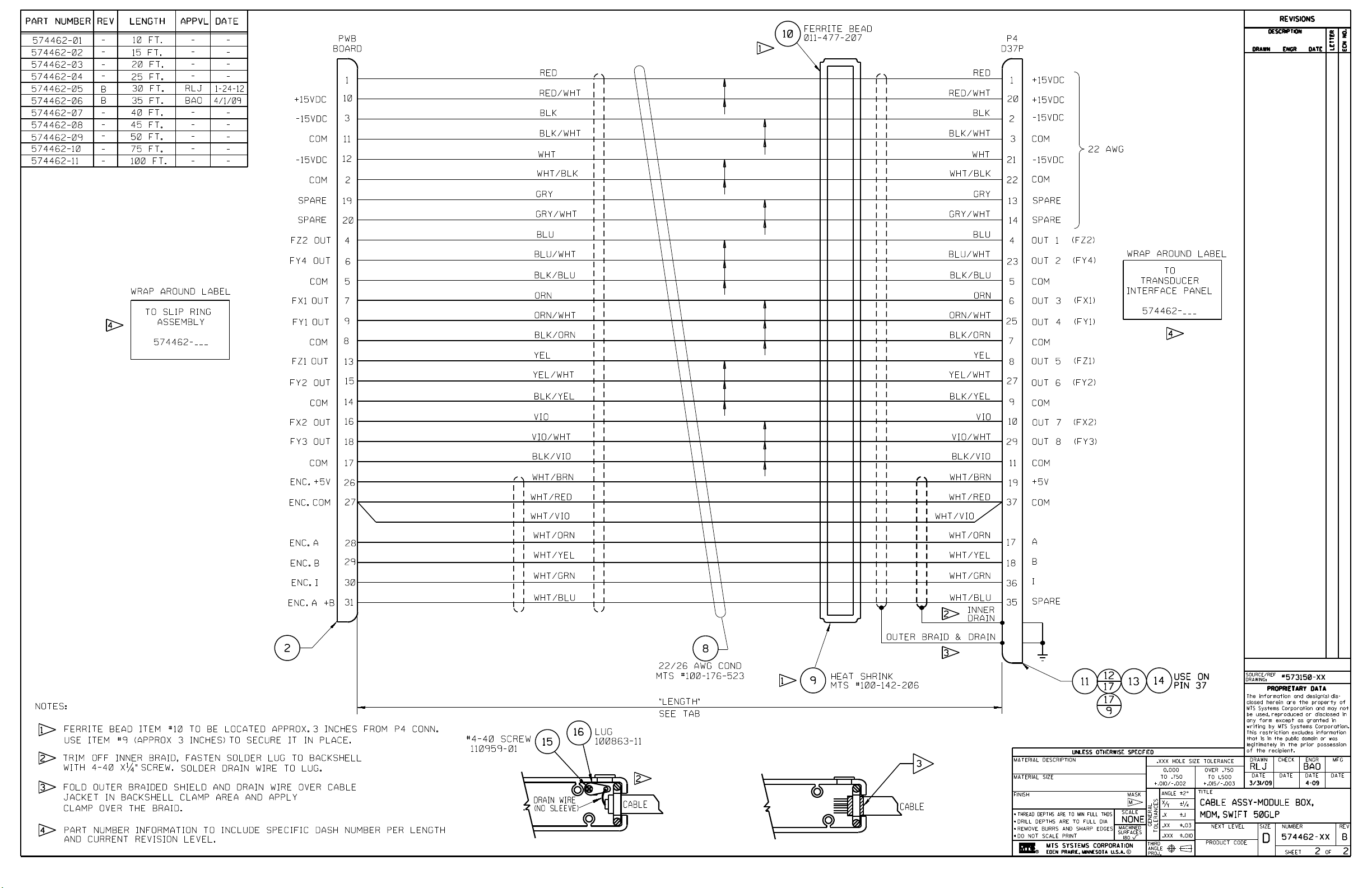
Page 92

Page 93

REVISIONS
DESCRIPTION
ECN NO
9/3/10
2-17-11MSRLJ
DATE
LETTER
B
10-0576
C
11-0034
D
11-0404
ENGR
RAWN
13
3
1
27
1214
1
WRAP AROUND LABEL
TO SWIFT
TRANSDUCER
CABLES
224-052
100-
TO SWIFT
MINI
11
AR
TRANSDUCER
INTERFACE
100-
AROUND LABEL
WRAP
224-
052
D
BOM CHANGES:
QTY ITEM 9
CHG
464822-01 (6 TO 4)
ITEM 10, 100-227-471
WAS 100-158-692
CHG QTY ITEM 11,
100-176-523 (2 FT - 1 FT)
ITEM 14, 100-226-155
WAS 119511-32
ADD ITEM 17, 100-203- 552
(1)
DRAWING CHANGES:
UPDATE FRONT PANEL
SILKSCREEN
ADD NOTE 3,
ADD VIEWS BACKSHELL ASSY
AND SHIELD CONNECTION .
MSKLQ
BOM CHANGE:
ADD ITEM 18,
700-003-419 (1 )
DRAWING CHANGE:
ADD FLAG NOTE 4:
ADD SERIAL NUMBER
LABEL. SEE MTS DOC.
700-003-419 FOR
REQD LABELING INFO.
KLQ
BUMPED REVISION FOR
T
RAC
EABILITY.
10-29-10
MS
6.00
9
1
4
(USE LOCTITE 222)
6
7
6
1
10
1
15
1
E8
E9
E1E2E3
E4
E7E5E6
1
1
ELD CONNECTION
SHI
2
1
D15P CONNECTOR
(JACKSCREW ONLY, USE LOCTITE 222)
J2B SHUNT B J2A SHUNT A
3
2
1
4
17
IAL LABEL
SER
TRANSDUCER
4
5
1
17
1 (USE LOCTITE 222)
1
TOP VIEW OF PWA BOARD
WITH D15P CONNECTORS, PLATE & FASTENERS
NOTES:
DISCARD FLAT WASHERS THAT ARE SUPPLIED.
1
USE
2
FOL
3
CABLE JACKET AND GROMMET IN BACKSHELL CLAMP AREA
AS SHOWN AND APPLY CLAMP OVER THE BRAID.
USE "SIZE H" 0.390 ID GROMMET (SUPPLIED WITH ITEM 14).
ADD SERIAL NUMBER LABEL. SEE MTS DOCUMENT
4
700-003-419 FOR REQUIRED LABELING INFORMATION.
LOCTITE 222 AND TORQUE TO 13 IN-LBS (1.5 N-M).
D OUTER BRAIDED SHIELD AND DRAIN WIRE OVER
BACKSHELL ASSEMBLY
MATERIAL DESCRIPTION
-----
MATERIAL SIZE
-----
FINISH
-----
THREAD DEPTHS ARE TO MIN FULL TH DS
DRILL DEPTHS ARE TO FULL DIA
REMOVE BURRS AND SHARP EDGES
DO NOT SCALE PRINT
MTS SYSTEMS CORPORATION
m
EDE
UNLESS OTHERWISE SPECIFIED
N PRAIRIE, MINNESOTA U.S.A.
MASK
M
SCALE
NONE
MACHINED
SURFACES
180
C
.XXX HOLE SIZE TOLERANCE
0.000
TO .750
+.010/-.002
GENERAL
TOLERANCES
THIRD
ANGLE
PROJ
X
.X
.XX
.XXX
OVER .750
TO 1.500
+.015/-.003
TITLE
2ANGLE
1/4
Y
.1
.03
NEXT LEVEL
.010
PRODUCT CODE
SOURCE/REF
DRAW
THE
DISCLOSED HEREIN ARE CONFIDENTIAL
AND THE PROPERTY OF MTS SYSTEMS
CORPORATION AND MAY NOT BE USED,
REPRODUCED OR DISCLOSED IN ANY
FORM EXCEPT AS GRANTED IN WRITING
BY MTS SYSTEMS CORPORATION. THIS
RESTRICTION EXCLUDES INFORMATION
THAT IS IN THE PUBLIC DOMAIN OR
WAS LEGITIMATELY IN THE PRIOR
POSSESSION OF THE RECIPIENT.
DRAWN
2-1
ABLE ASSY-LPTI TO
C
MINI TI, SWIFT, ROHS
-
-
-
-
ING
PROPRIETARY DATA
INFORMATION AND DESIGN(S)
ENGR
CK
RLJ
9-10 -
SIZE
D
CHE
DATEDATE
S
M
-
DATE
2-19-10 -
NUMBER
100-224-052
SHEET OF
1
MFG
DATE
-
REV
D
2
Page 94
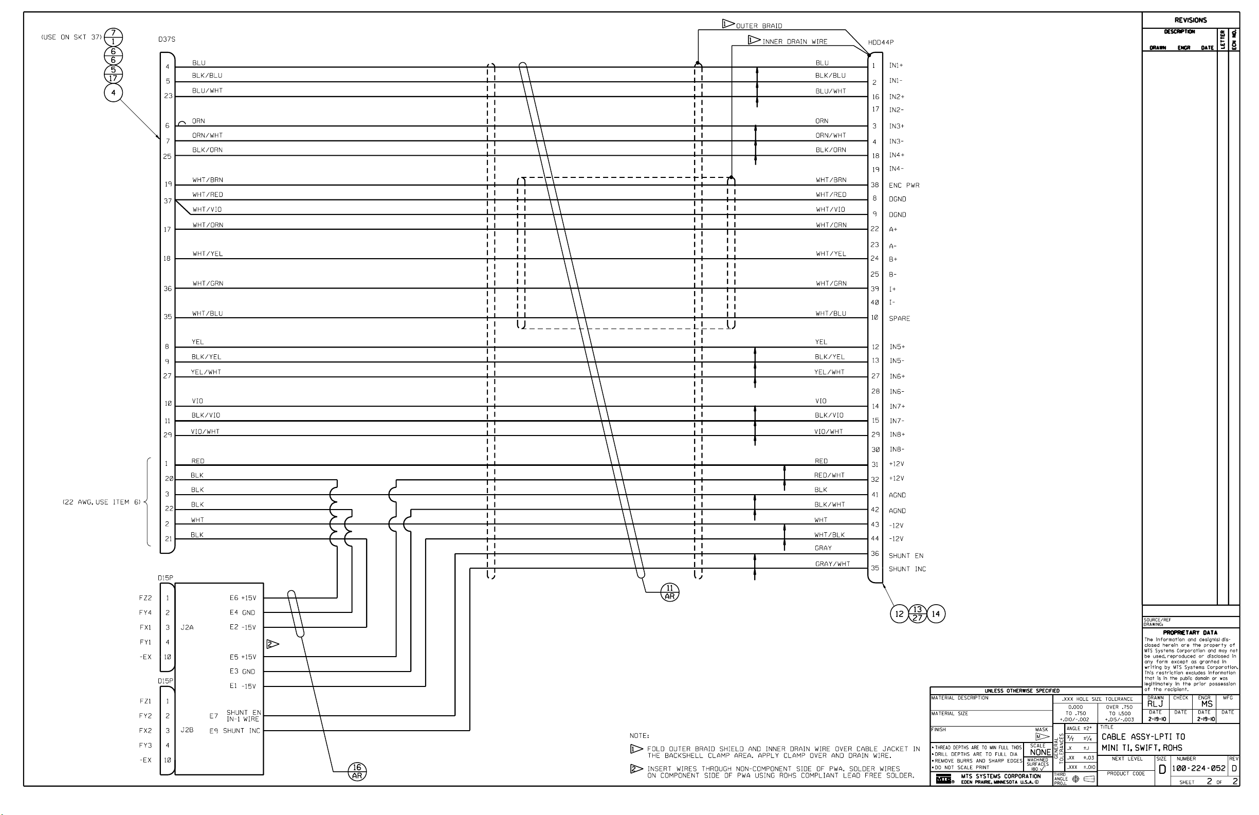
Page 95

SWIFT 50 GLP Mechanical Drawings
SWIFT 50 GLP Mechanical Drawings
SWIFT 50 GLPS Mechanical Drawings
Part Number Part Description
569844xx
570594xx
100161435
700002218
700002219
700002520
700003435
700003439
700003458
LUG NUT, MODIFICATION-SWIFT 50GLP
CONDUIT BRKT- SLIP RING ASSY-SWIFT 50GLP
ANTI-ROTATE ASSY- CUST/USER,SWIFT 50GLP
DISK RIM (FRT) CUSTOMER DIMENSIONAL DWG
DISK RIM (REAR) CUSTOMER DIMENSIONAL DWG
ANTI-ROTATE BRKT WELDMENT-SWIFT 50 REF
REFERECE DIMENSION ASSEMBLY-SWIFT 50GLP
SWIFT 50GLP MOMENT LDS DETERMINATION DWG
REFERENCE-SPINDLE SPACER, SWIFT 50GLP
SWIFT 50 GLP Sensors Assembly Drawings
95
Page 96

Page 97

Page 98

Page 99

Page 100

 Loading...