


Safety • Assembly • Operation • Tips & Techniques • Maintenance • Troubleshooting • Parts Lists • Warranty
OPERATOR’S MANUAL
Model OEM-190-032 190-032-101
42-inch Two-Stage Snow Thrower Attachment
For FastAttach™ Compatible Lawn Tractors & Garden Tractors
IMPORTANT
READ SAFETY RULES AND INSTRUCTIONS CAREFULLY BEFORE OPERATION
Warning: This unit is equipped with an internal combustion engine and should not be used on or near any unimproved forest-covered, brushcovered or grass-covered land unless the engine’s exhaust system is equipped with a spark arrester meeting applicable local or state laws (if any). If a spark arrester is used, it should be maintained in effective working order by the operator. In the State of California the above is required by law (Section 4442 of the California Public Resources Code). Other states may have similar laws. Federal laws apply on federal lands. A spark arrester for the muffler is available through your nearest engine authorized service dealer or contact the service department, P.O. Box 361131 Cleveland, Ohio 44136-0019.
|
|
FORM NO. 769-01933 |
PRINTED IN U.S.A. |
MTD LLC, P.O. BOX 361131 CLEVELAND, OHIO 44136-0019 |
6/2005 |
This Operator’s Manual is an important part of your snow thrower attachment. It will help you assemble, prepare and maintain the unit for best performance. Please read and understand what it says.
TABLE OF CONTENTS
1. Rider Model Identification................................ |
Page 3 |
9. Controls........................................................... |
Page 20 |
||
2. |
Snow Thrower Attachment Safety ................... |
Page 4-5 |
10.Operation........................................................ |
Page 21 |
|
3. |
Carton Contents .............................................. |
Page 6-7 |
11. Adjustments ................................................... |
Page 22 |
|
4. Assembly Models 600-649 & 800 Series........ |
Page 8-13 |
12. |
Maintenance.................................................. |
Page 23 |
|
5. |
Assembly All Model 700 Series....................... |
Page 14-15 |
13. |
Parts List........................................................ |
Page 24-29 |
6. |
Attaching Controls........................................... |
Page 16 |
13. |
Notes ............................................................. |
Page 30-31 |
7. |
Attaching Auger Housing................................ |
Page 17 |
Warranty.......................................................... |
Page 32 |
|
8. |
Routing Upper & Lower Drive Belts................. |
Page 18-19 |
|
|
|
Finding and Recording Model Number
BEFORE YOU START ASSEMBLING YOUR NEW EQUIPMENT,
please locate the model plate and copy the information from it in this Operator’s Manual for future reference. The information on the model plate is very important if you need help from our Customer Support Department or your authorized dealer. You can locate it by looking on the top rear portion of the auger housing:
Model Number |
Serial Number |
*Locate the model plate on your snow thrower attachment and copy the information from it in the space provided above for future reference.
Customer Support
Please do NOT return the unit to the retailer from which it was purchased, without first contacting Customer Support.
If you have difficulty assembling this product or have any questions regarding the controls, operation, or maintenance of this unit, you can seek help from the experts. Choose from the options below:
•Visit www.mtdproducts.com. Click on the Service & Support menu option.
•Phone a Customer Support Representative at 1-800-800-7310.
•Please have your unit’s model number and serial number ready when you call. See above to locate this information. You will be asked to enter the serial number in order to process your call.
2
Model Plate
1 |
30 |
3 |
81 |
11 |
63 |
6 |
47 |
C3 |
-00- |
LLX |
20 |
OB |
28 |
DT. |
-00- |
O. |
30 |
MP |
38 |
Figure 1
Sample Model Number
1 3 A M 7 9 0 G 0 0 0
Indicates Model Series 700
Figure 2
FastAttach™ Snow
Thrower Attachment
NOTE: This Operator’s Manual covers several models. Snow thrower hook-up instructions vary by model. Not all features discussed in this manual are applicable to all snow thrower attachments.
To The Owner
Model OEM-190-032 42-inch two-stage snow thrower attachement is designed for use on FastAttach™ Compatible Lawn Tractors and Garden Tractors ONLY. It will NOT fit nor operate properly or safely on ANY other tractor.
Determine The Model
ofYour Rider
Since this manual is designed for installation of your new snow thrower attachment on several different rider units, it is important for you to determine which model of rider you have. Therefore you will know which set of instructions in the following pages to follow.
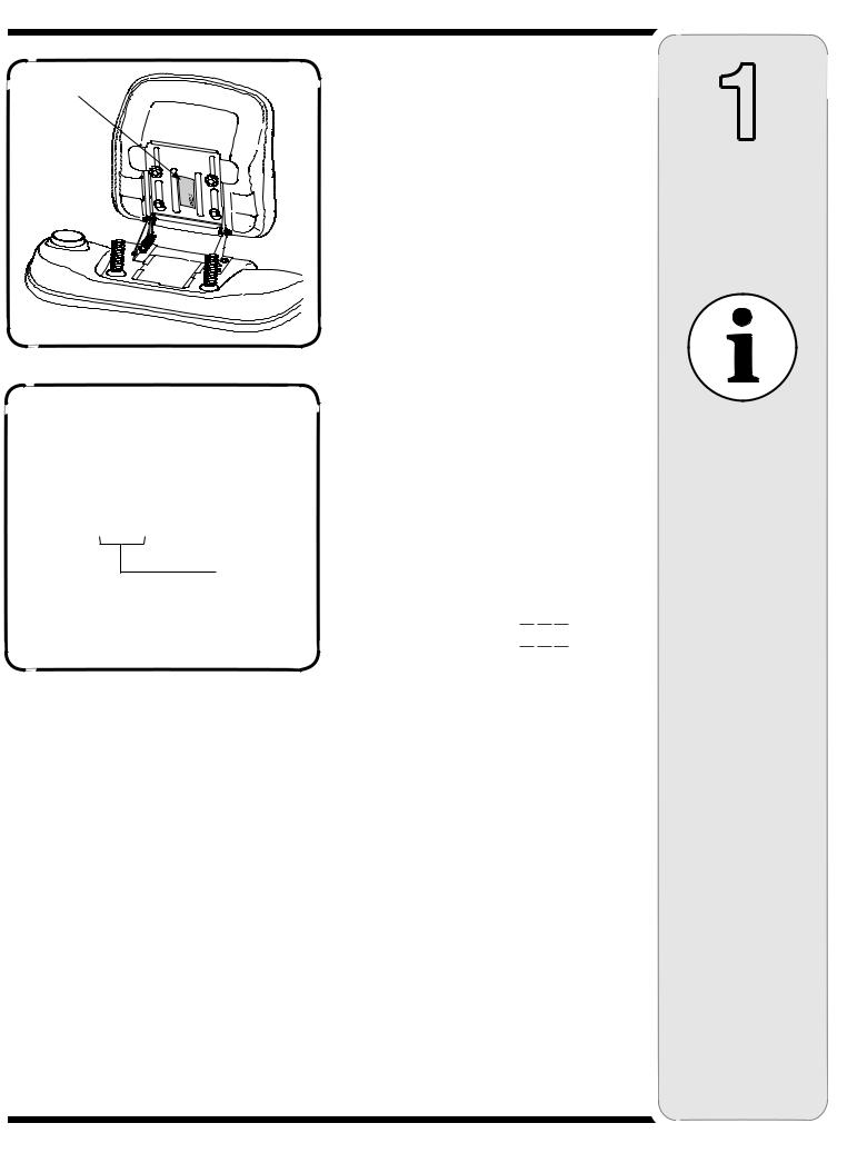
To determine which model of rider you have, you will need to locate the rider’s model plate, located under the seat. Simply flip the seat up and locate the model plate, which will consist of an 11 digit/letter model number and a serial number. For ease in this installation and for future use, copy your rider’s model number & serial number below now:
Rider Model Number:__ __ __ __


 __ __ __ __
Rider Serial Number:_________________________
The 5th, 6th & 7th numbers from the left in your model number determine your rider’s model series. See Figure 2.
When you fill in your model number in the space above, the actual model series number should fall into the gray shaded area.
Now that you have determined what model rider you are attaching this snow thrower attachment to, follow the instructions on the following pages according to your model of rider.
1
Rider Model Identification
NOTE:
References to LEFT and RIGHT indicate the left and right sides of the tractor when facing forward in the operator’s position. Reference to the FRONT indicates the grille end; to the REAR, the rear end of the rider.
3

2
Safe
Operation Practices
WARNING
This symbol points out important safety instructions which, if not followed, could endanger the personal safety and/or property of yourself and others. Read and follow all instructions in this manual before attempting to operate this machine. Failure to comply with these instructions may result
in personal injury. When you see this symbol.
HEED ITS WARNING!
Your Responsibility
Restrict the use
of this power machine to persons who read, understand
and follow the warnings and instructions
in this manual
and on the machine.
WARNING: Engine Exhaust, some of its constituents, and certain vehicle components contain or emit chemicals known to State of California to cause cancer and birth defects or other reproductive harm.
DANGER: This machine was built to be operated according to the rules for safe operation in this manual. As with any type of power equipment, carelessness or error on the part of the operator can result in serious injury. This machine is capable of amputating hands and feet and throwing objects. Failure to observe the following safety instructions could result in serious injury or death.
Training
1.Read, understand, and follow all instructions on the machine and in the manual(s) before attempting to assemble and operate. Keep this manual in a safe place for future and regular reference and for ordering replacement parts.
2.Be familiar with all controls and their proper operation. Know how to stop the machine and disengage them quickly.
3.Never allow children under 14 years old to operate this machine. Children 14 years old and over should read and understand the operation instructions and safety rules in this manual and should be trained and supervised by a parent.
4.Never allow adults to operate this machine without proper instruction.
5.Thrown objects can cause serious personal injury. Plan your snow-throwing pattern to avoid discharge of material toward roads, bystanders and the like.
6.Keep bystanders, helpers, pets and children at least 75 feet from the machine while it is in operation. Stop machine if anyone enters the area.
7.Exercise caution to avoid slipping or falling, especially when operating in reverse.
Preparation
1.Thoroughly inspect the area where the equipment is to be used. Remove all doormats, newspapers, sleds, boards, wires and other foreign objects, which could be tripped over or thrown by the auger/impeller.
2.Always wear safety glasses or eye shields during operation and while performing an adjustment or repair to protect your eyes. Thrown objects which ricochet can cause serious injury to the eyes.
3.Do not operate without wearing adequate winter outer garments. Do not wear jewelry, long scarves or other loose clothing, which could become entangled in moving parts. Wear footwear which will improve footing on slippery surfaces.
4.Use a grounded three-wire extension cord and receptacle for all units with electric start engines.
5.Adjust collector housing height to clear gravel or crushed rock surfaces.
6.Disengage all control levers before starting the engine.
7.Never attempt to make any adjustments while engine is running, except where specifically recommended in the operator’s manual.
8.Let engine and machine adjust to outdoor temperature before starting to clear snow.
9.To avoid personal injury or property damage use extreme care in handling gasoline. Gasoline is extremely flammable and the vapors are explosive. Serious personal injury can occur when gasoline is spilled on yourself or your clothes, which can ignite. Wash your skin and change clothes immediately.
a.Use only an approved gasoline container.
b.Extinguish all cigarettes, cigars, pipes and other sources of ignition.
c.Never fuel machine indoors.
d.Never remove gas cap or add fuel while the engine is hot or running.
e.Allow engine to cool at least two minutes before refueling.
f.Never over fill fuel tank. Fill tank to no more than ½ inch below bottom of filler neck to provide space for fuel expansion.
g.Replace gasoline cap and tighten securely.
h.If gasoline is spilled, wipe it off the engine and equipment. Move machine to another area. Wait 5 minutes before starting the engine.
i.Never store the machine or fuel container inside where there is an open flame, spark or pilot light (e.g. furnace, water heater, space heater, clothes dryer etc.).
j.Allow machine to cool at least 5 minutes before storing.
4

Operation
1.Do not put hands or feet near rotating parts, in the auger/impeller housing or chute assembly. Contact with the rotating parts can amputate hands and feet.
2.The auger/impeller control lever is a safety device. Never bypass its operation. Doing so makes the machine unsafe and may cause personal injury.
3.The control levers must operate easily in both directions and automatically return to the disengaged position when released.
4.Never operate with a missing or damaged chute assembly. Keep all safety devices in place and working.
5.Never run an engine indoors or in a poorly ventilated area. Engine exhaust contains carbon monoxide, an odorless and deadly gas.
6.Do not operate machine while under the influence of alcohol or drugs.
7.Muffler and engine become hot and can cause a burn. Do not touch.
8.Exercise extreme caution when operating on or crossing gravel surfaces. Stay alert for hidden hazards or traffic.
9.Exercise caution when changing direction and while operating on slopes.
10.Plan your snow-throwing pattern to avoid discharge towards windows, walls, cars etc. Thus, avoiding possible property damage or personal injury caused by a ricochet.
11.Never direct discharge at children, bystanders and pets or allow anyone in front of the machine.
12.Do not overload machine capacity by attempting to clear snow at too fast of a rate.
13.Never operate this machine without good visibility or light. Always be sure of your footing and keep a firm hold on the handles. Walk, never run.
14.Disengage power to the auger/impeller when transporting or not in use.
15.Never operate machine at high transport speeds on slippery surfaces. Look down and behind and use care when backing up.
16.If the machine should start to vibrate abnormally, stop the engine, disconnect the spark plug wire and ground it against the engine. Inspect thoroughly for damage. Repair any damage before starting and operating.
17.Disengage all control levers and stop engine before you leave the operating position (behind the handles). Wait until the auger/impeller comes to a complete stop before unclogging the chute assembly, making any adjustments, or inspections.
18.Never put your hand in the discharge or collector openings. Always use the clean-out tool provided to unclog the discharge opening. Do not unclog chute assembly while engine is running. Shut off engine and remain behind handles until all moving parts have stopped before unclogging.
19.Use only attachments and accessories approved by the manufacturer (e.g. wheel weights, tire chains, cabs etc.).
20.If situations occur which are not covered in this manual, use care and good judgment. Contact your dealer or call (800) 800-7310 for assistance and the name of your nearest servicing dealer..
Maintenance & Storage
1.Never tamper with safety devices. Check their proper operation regularly. Refer to the maintenance and adjustment sections of this manual.
2.Before cleaning, repairing, or inspecting machine disengage all control levers and stop the engine. Wait until the auger/impeller come to a complete stop. Disconnect the spark plug wire and ground against the engine to prevent unintended starting.
3.Check bolts and screws for proper tightness at frequent intervals to keep the machine in safe working condition. Also, visually inspect machine for any damage.
4.Do not change the engine governor setting or over-speed the engine. The governor controls the maximum safe operating speed of the engine.
5.Snow thrower shave plates and skid shoes are subject to wear and damage. For your safety protection, frequently check all components and replace with original equipment manufacturer’s (OEM) parts only. “Use of parts which do not meet the original equipment specifications may lead to improper performance and compromise safety!”
6.Check controls periodically to verify they engage and disengage properly and adjust, if necessary. Refer to the adjustment section in this operator’s manual for instructions.
7.Maintain or replace safety and instruction labels, as necessary.
8.Observe proper disposal laws and regulations for gas, oil, etc. to protect the environment.
9.Prior to storing, run machine a few minutes to clear snow from machine and prevent freeze up of auger/impeller.
10.Never store the machine or fuel container inside where there is an open flame, spark or pilot light such as a water heater, furnace, clothes dryer etc.
11.Always refer to the operator’s manual for proper instructions on off-season storage.
Do not modify engine
To avoid serious injury or death, do not modify engine in any way.Tampering with the governor setting can lead to a runaway engine and cause it to operate at unsafe speeds. Never tamper with factory setting of engine governor.
Notice regarding Emissions
Engines which are certified to comply with California and federal EPA emission regulations for SORE (Small Off Road Equipment) are certified to operate on regular unleaded gasoline, and may include the following emission control systems: Engine Modification (EM) and Three Way Catalyst (TWC) if so equipped.
Your Responsibility
Restrict the use of this power machine to persons who read, understand and follow the warnings and instructions in this manual and on the machine.
2
Safe
Operation Practices
WARNING
This symbol points out important safety instructions, which if not followed, could endanger the personal safety and/or property of yourself and others. Read and follow all instructions in this manual before attempting to operate this machine. Failure to comply with these instructions may result in personal injury.
When you see this symbol.
HEED IT’S WARNING!
Your Responsibility
Restrict the use
of this power machine to persons who read, understand
and follow the warnings and instructions
in this manual
and on the machine.
5

3
Carton
Contents
If you are missing any parts, please do not contact the retailer where you purchased this unit, call MTD directly at 1-330-220-4MTD or
toll free at 1-800-800-7310.
Self-Adhesive
Reflectors 
Belt Keeper & Hardware
Extension Spring
Idler Pulley & Pin
Wing Nut
Cable Ties
Belt Keeper
& Hardware 
Assembly Brackets
& Hardware
Upper V-Belt (754-0498)
Lift Handle |
Undercarriage Assembly |
Assembly |
|
Upper V-Belt (754-0435)
Upper V-Belt (754-0481) 
Auger Housing Assembly w/ Linkage
Extension Spring
 Idler Assembly
Clamp
Cotter Pin
Chute Directional Support w/ Tilt Lever & Upper Crank Rod
Spare Shear Bolts
& Hex Lock Nuts
Figure 3
6

CONTENTS OF CARTON
Before beginning installation, remove all parts from the carton to make sure everything is present. Carton contents are listed below and shown in Figure 3. Hardware part numbers are shown in parentheses.
•One Auger Housing Assembly w/ Lower V-belt
•One Undercarriage Assembly (w/ Upper V-belt 754-0371A)
•One Idler Assembly w/ Extension Spring (732-0594A)
•One Idler Pulley (756-0627B) and Pin (650-0040) w/ Hair Pin Clip (714-0145)
•One Belt Keeper (747-04135) w/ Bell Washer (736-0270) Jam Nut (712-0298) & Hex Nut (712-3006)
•One Lift Handle Assembly
•One Upper Chute Crank Rod
•One Chute Directional Support w/ Tilt Lever
•Five Cable Ties (725-0157)
•Two Spare Shear Bolts (710-0890A) & Hex Lock Nuts (712-0429)
•One Cotter Pin (714-0507)
•Two Self-adhesive Reflectors (730-3000)
•One Upper V-belt (754-0481)
•One Upper V-belt (754-0435)
•One Upper V-belt (754-0490)
•Left & Right Assembly Brackets (683-04215 & 683-04214) & Hardware (710-0514 Hex Screw, 712-04065 Flange Nut, 738-0143 Shoulder Screw & 712-04063 Flange Nut)
•Belt Keeper (711-1000) & Flange Lock Nut (712-04063 )
•Wing Nut (712-04100)
•16mm Clamp (726-0354)
•Extension Spring (732-04237)
3
Carton
Contents
If you are missing any parts, please do not contact the retailer where you purchased this unit, call MTD directly at
1-330-220-4MTD or toll free at 1-800-800-7310.
7
4 |
WARNING: Before installing attach- |
Weld Pin |
|
ment, place tractor on a firm and level |
|||
|
|||
surface. Place the PTO in the disen- |
|
||
gaged (OFF) position, set the parking |
|
||
brake, shut engine off and remove key |
|
||
to prevent unintended starting. |
|
||
Assembly |
NOTE: References to LEFT and RIGHT indicate the left |
|
|
Model Series |
and right sides of the tractor when facing forward in the |
|
|
operator’s position. Reference to the FRONT indicates |
|
||
600-649 & |
|
||
the grille end; to the REAR the drawbar end. |
|
||
All 800 series. |
IMPORTANT: You must first figure out which model of |
|
|
|
rider you are attaching this snow thrower to. Refer to |
|
|
|
Determine Your Model of Rider on page 3 of this manual |
|
|
|
to determine what model rider you are attempting to |
|
|
|
install this attachment to. Then proceed to the applicable |
|
|
|
instructions for your model of rider. |
|
|
|
Your tractor’s cutting deck, PTO belt and front deck |
|
|
|
stabilizer bracket must be removed prior to mounting |
|
|
WARNING |
the snow thrower attachment. Refer to your tractor’s |
|
|
Operator’s Manual for detailed instructions. If your |
|
||
Before installing |
tractor is equipped with any front-end accessory (i.e. |
|
|
attachment, place |
front bumper kit), it must also be removed. |
|
|
|
|
||
tractor on a firm |
Mounting the |
|
|
and level surface. |
|
||
Idler Pulley and Pin |
|
||
Place the PTO in |
|
||
the disengaged |
(Manual PTO Tractors equipped with |
|
|
(OFF) position, set |
a 38or 42-inch deck ONLY) |
|
|
the parking brake, |
NOTE: If you engage your tractor’s cutting deck by |
|
|
shut engine off and |
|
||
using your left hand to pivot a lever forward, your tractor |
|
||
remove key to prevent |
has a Manual PTO. If you engage your tractor’s cutting |
|
|
unintended starting. |
deck by pulling outward on a small knob located on the |
|
|
|
tractor’s dash, your tractor has an Electric PTO. |
|
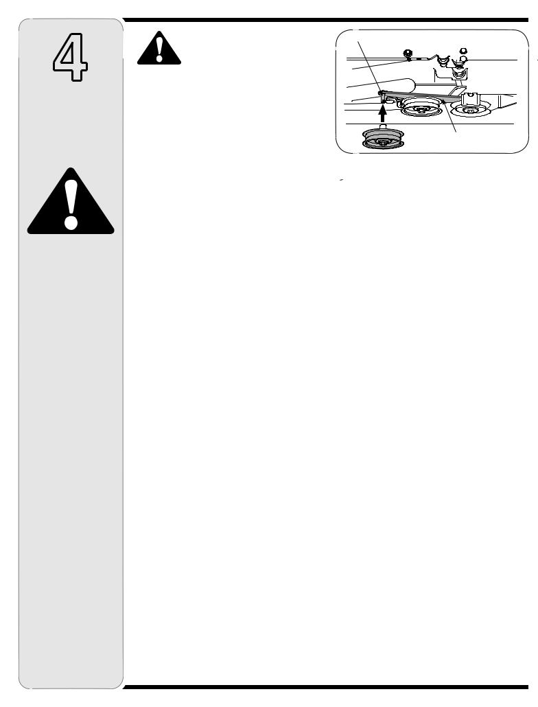
The idler pulley and pin (packaged separately, refer to pages 6-7) must be installed to the PTO engagement plate of all manual PTO tractors with a dual-belt drive 38or 42-inch cutting deck. If applicable, proceed as follows. Otherwise, proceed to Mounting the Undercarriage Assembly.
Locate the PTO engagement plate beneath your tractor. See Figure 4.
Note the location of the weld pin on the rear portion of the PTO engagement plate. This pin is where the deck brake cable attaches, when operating the tractor with the cutting deck mounted.
Remove the hair pin clip from the idler pulley and pin (packaged separately). Refer to pages 6-7.
Position the idler pulley and pin onto the weld pin of the PTO engagement plate and secure with the hairpin clip just removed.
NOTE: This Idler pulley must be removed when remounting the tractor’s cutting deck.
PTO Engagement Plate
Figure 4
8
Flange Nut, Washer &
Shoulder Spacer
Double-idler Bracket/Front Pulley
Figure 5
 3-in. Hex Bolt
Undercarriage

 Spacers
Shoulder Spacer |
|
|
(Facing Up) |
|
|
Flat Washer |
Shoulder Spacer |
|
(Facing Down) |
||
Flange Nut |
||
|
||
|
Figure 6 |
Bell Washer
Jam Nut
Figure 7
Reversing the
Idler Assembly Hardware
(Manual PTO Garden Tractors equipped with a 46-inch deck ONLY)
If you’re mounting this snow thrower attachment to a tractor equipped with any deck other than a manually engaged 46-inch, proceed to either:
1.Mounting the Idler Assembly (for tractors equipped with a 42, 46, 50 & 54-inch deck ONLY) in this section
2.Mounting the Idler Pulley and Pin (for Manual PTO tractors equipped with a 38or 42-inch deck ONLY) previously in this section, or
3.Mounting the Undercarriage Assembly (all tractors not mentioned above) on page 12.
These instructions are for mounting this snow thrower attachment to a GARDEN TRACTOR (Model Series 800) equipped with a Manual PTO and a 46-inch deck.
NOTE: If you own a Manual PTO Lawn Tractor with a 46-inch deck, you can disregard the following steps; they are unnecessary. A LAWN TRACTOR is any 600649 Series mower, an 800 Series mower is a GARDEN TRACTOR. Refer to Determine Your Model of Rider on page 3 of this manual to determine what model rider you are attempting to install this attachment to.
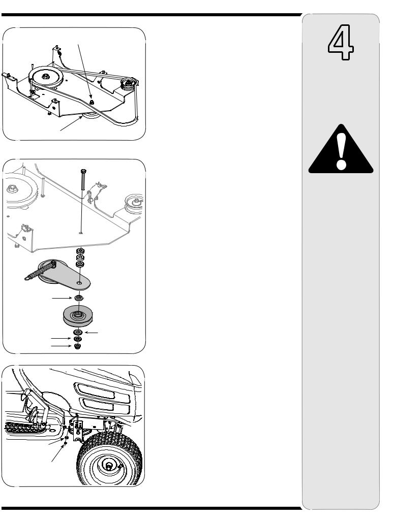
1.Remove the flange nut, washer and shoulder spacer which secures the double-idler bracket to the undercarriage. See Figure 5.
2.Remove the 3-inch hex bolt from the bottom of the front pulley, to free it from the undercarriage.
3.Reassemble with the 3-inch hex bolt on top of the undercarriage and the flange nut securing the pulley from the bottom. See Figure 6.
IMPORTANT: Components must be reassembled in the exact order illustrated in Figure 6.
Mounting the Belt Keeper
(Manual PTO Garden Tractors equipped with a 46-inch deck ONLY)
The belt keeper and hardware (packaged separately, refer to page 6-7) must be installed around the engine pulley of all Manual PTO Garden Tractors with a 46-inch cutting deck. To do so, proceed as follows:
1.Locate the engine pulley by looking beneath the front area of your tractor.
2.Secure the belt keeper to the inside of the tractor’s frame with the hex nut, bell washer and jam nut as shown in Figure 7.
3.Make certain the cupped portion of the bell washer is facing IN before tightening the jam nut.
4
Assembly
Model Series 600-649 & All 800 series.
WARNING
Before installing attachment, place tractor on a firm and level surface. Place the PTO in the disengaged (OFF) position, set the parking brake, shut engine off and remove key to prevent unintended starting.
9
4
Assembly
Model Series 600-649 & All 800 series.
WARNING
Before installing attachment, place tractor on a firm and level surface. Place the PTO in the disengaged (OFF) position, set the parking brake, shut engine off and remove key to prevent unintended starting.
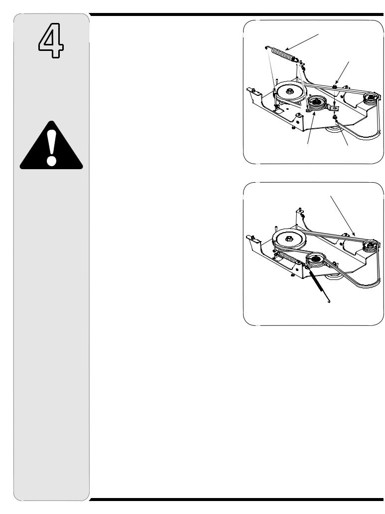
Mounting the Idler Assembly
(42, 46, 50, 54 inch Decks with Electric PTO)
If you’re mounting this snow thrower attachment to a tractor equipped with any deck other than a 42, 46, 50 or 54-inch deck with electric PTO, proceed to Mounting the Undercarriage Assembly (all tractors).
However, if you’re mounting this snow thrower attachment to a tractor equipped with a 42, 46, 50 or 54-inch deck with electric PTO, proceed as follows:
NOTE: If you engage your tractor’s cutting deck by using your left hand to pivot a lever forward, your tractor has a Manual PTO. If you engage your tractor’s cutting deck by pulling outward on a small knob located on the tractor’s dash, your tractor has an Electric PTO.
1.Remove the flange nut noted in Figure 8, which secures the double-idler bracket to the undercarriage. Leave the Shoulder Spacer in place.
2.Attach the idler assembly (packaged separately) over the hex screw and shoulder spacer on the surface of the undercarriage. See Figure 8.
3.Fasten the idler bracket to the undercarriage with the hardware just removed. See Figure 8.
4.Attach one end of the extension spring (732-0594A) to the hole in the idler assembly just mounted and the opposite end of the extension spring to the keeper pin as illustrated in Figure 8.
5.Position the upper v-belt (754-0371A) as illustrated in Figure 9.
NOTE: For a complete detailed diagram of how to route the upper v-belt, see Routing The Upper V-belt later in this manual.
Extension Spring
Flange Nut
Idler Bracket & Pulley |
Shoulder Spacer |
Figure 8
Upper V-belt (754-0371A
Figure 9
10
 Loading...