


Row Marker
OEM-290-257 / 290-257-081
IMPORTANT: Your new row marker is designed to attach to the Troy-Bilt Hiller-Furrower attachment. If you don’t have HillerFurrower, call us or visit www.troybilt.com to place an order:
OEM-290-250 for Horse Model tillers
OEM-290-251 for Pony, Econo-Horse and Junior Model tillers
Introduction
Row Marker OEM-290-257 will help you lay out your garden with speed, accuracy and convenience — without the bother of stakes, strings, tape measures and other tools. It’s fast and easy to assemble, mount and use with your TROY-BILT HORSE Model, ECONO-HORSE, PONY or JUNIOR Model tiller too! Just follow these assembly & use instructions.
NOTE: If you ordered a Hiller-Furrower with your Row Marker, be sure to install the Furrower blade first, as the Row Marker attaches directly to the Furrower blade and must be used with it. Separate assembly instructions are included with the HillerFurrower. If you already had a Hiller-Furrower, just attach the Furrower blade to your TROY-BILT Tiller as always and follow the Row Marker instructions here.
Be sure you received all the hardware and parts listed below. If anything is missing or damaged, please write or give us a call using the information provided on the back cover of this manual.
REF. |
PART |
|
|
No. |
No. |
DESCRIPTION |
QTY. |
|
|
|
|
1 |
1904522 |
Main Support & Yoke Assembly |
....... 1 |
2 |
GW-1594 |
Marker Blade ..................................... |
1 |
3 |
1904524 |
Main Marker Arm .............................. |
1 |
41904523 Marker Arm Extension (w/ stop pin). 1
5GW-1837 Hardware Package (includes below) . 1
GW-9347 |
Hitch Pin ........................................... |
1 |
GW-9828 |
Hex Nut, #10-24................................ |
2 |
1100135 |
Screws, #10-24 x 1 ........................... |
2 |
GW-9786 |
Thumb Screws, 1/4-20...................... |
2 |
GW-1596 |
Nut Bar.............................................. |
1 |
|
|
|
 WARNING
Contents of Carton
Step 1: Attach Main Support to the Furrower
TO PREVENT INJURY FROM MOVING PARTS OR HOT SURFACES:
•Stop the engine and wait for all moving parts to stop.
•Disconnect the spark plug wire from the spark plug and allow the muffler to cool.
Tools Needed
•9/16” wrench (or adjustable wrench)
•3/8” wrench (or adjustable wrench)
•Pliers
1.Using a 9/16” wrench or adjustable wrench, first remove the two 3/8” hex nuts and lockwashers that secure the furrower blade to its bracket.
2.Position the Row Marker Main Support on the two 3/8”-16 x 1-1 /2” long bolts (A and B in Photo 1).
Note: The Stop Bar on the Main Support faces out toward the operator and the two bottom holes in the Main Support are used for mounting.
3.Replace both lockwashers and hex nuts and tighten securely.
4.Using a 9/16” wrench, remove hex nuts and lockwashers from bolts “A” and “B“, install Main Support on bolts as shown. Replace nuts and washers.

Photo 1
Step 2: Mount the Marker Blade on the Marker Arm Extension
1.The Marker Arm Extension is the 27” long solid steel shaft with a stop pin at one end and two mounting holes at the other end. Place this arm on a flat surface (table, etc.) for working ease.
2.Slide the extension arm into the “V-shape” of the blade (see Photo 2), aligning the holes in the arm with the holes in the blade. Be sure the stop pin at the other end of the arm and the points of the blade are facing you.
3.Insert two #10-24 x 1” lg. round head screws through the blade and the arm holes and secure them with two #10-24 hex nuts (the nuts have permanently attached
star washers) as shown in Photo 3. The star washer side of the hex nut should face the Extension Arm. Tighten firmly with a 3/8” wrench. Use a screwdriver, if necessary, to keep the screws from turning while the nuts are being tightened.
Step 3: Slide Marker Arm Extension into the Main Arm
1.With the stop pin at the end of the Extension Arm and the holes facing you, slide the Extension Arm into the hollow Main Arm. See Photo 4.
Note: You may push the Extension Arm in as far as you wish for now. When completely assembled, you’ll be able to immediately adjust to whatever widths between rows you may want just by retracting or extending the Extension Arm.
Photo 2
Photo 3
Photo 4
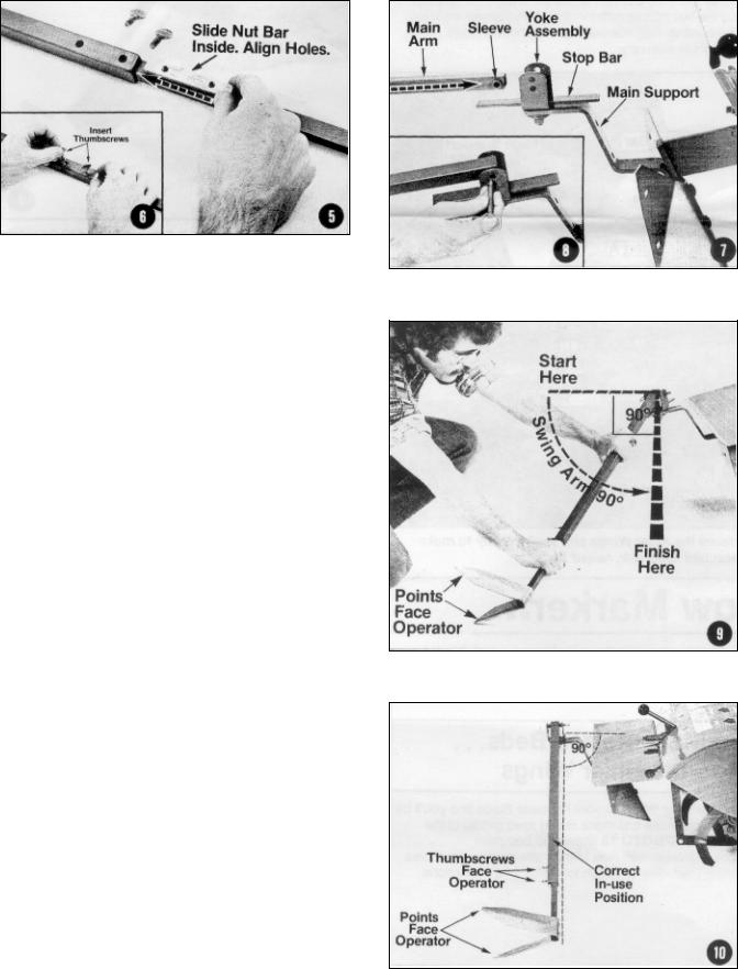
Photo 5 & Photo 6 (inset)
2.Insert the Nut Bar lengthwise into the Main Arm as shown in Photo 5. Continue to slide the bar in until the two tapped holes in the Nut Bar are aligned with the two holes at the end of the Main Arm. When the holes are aligned, and the Extension Arm is at the length you want, then secure the arms together with two 1/4”-20 x 1/2” long thumbscrews (see Photo 6 inset) turning them until they’re tight.
Note: To adjust the Marker Extension Arm in or out to suit a row width for your application, simply unthread the thumbscrews one full turn, then adjust the arm length before retightening the thumbscrews. Fully extended, the Row Marker is 49-3/4” long; fully retracted, 28”.
Step 4: Attach Main Marker Arm to the Main Support
The Main Marker Arm connects to the Yoke at the top of the Main Support with a quick-release pin.
1.Align the sleeve located at the end of the Main Arm between either the top set or bottom set of holes on the yoke sides. See Photo 7.
2.Once the sleeve is lined up, insert the quick release pin (Photo 8, Inset). At this point, the Main Arm rests on the Stop Bar and points straight back from the rear of the tiller.
IMPORTANT: The top and bottom sets of holes on the yoke sides allow the marker arm to rest on the Stop Bar at the proper angle regardless of whether the Extension Arm is fully extended or retracted. When the extension arm is more than 50% extended, use the bottom set of holes, otherwise use the top set of holes.
3.Pivot the Marker Arm from its “straight back” position a full 90° to either the right or the left in order to get the Marker Arm to point out to the side of the Tiller. Whether you decide to pivot right or left, just be sure the points of the Marker Blade face back toward the operator after the arm has been pivoted. See Photo 9 and Photo 10 for the correct in-use position.
Photo 7 & Photo 8 (inset)
Photo 9
Photo 10
 Loading...