


Bolo Tine Kit
OEM-290-253 / 290-253-081
for HORSE TM, ECONO HORSE TM,and PONY® Tillers
THANK
YOU!
Installation Instructions
Thanks for buying new bolo tines. These tines were designed for your model tiller and will handle all of your tilling needs including sod busting, seedbed preparation, cultivating, and turning under crop residue.
How To Use These
 Instructions
These instructions apply only to owners of the following tillers:
HORSETM Model
ECONO HORSETM Model
PONY® Model
First, read the general information given for all model tillers on Pages 1 through 4. You will then be directed to installation instructions for your particular model tiller. Carefully look at the adjacent figures while following the step-by-step instructions. Finally, see the Bolo Tines Maintenance Section on Page 16.
Tools Needed
Wrenches (two 9/16 inch)
Screwdriver (medium-sized)
Soft Rubber Mallet
Penetrating Oil
Metal File (needed only if tine holders are also removed)
How To Reach Us
If you have any questions about removing or installing tines, please refer to the “Customer Assistance” information on the back cover.
Attention!
HORSE Model Owners
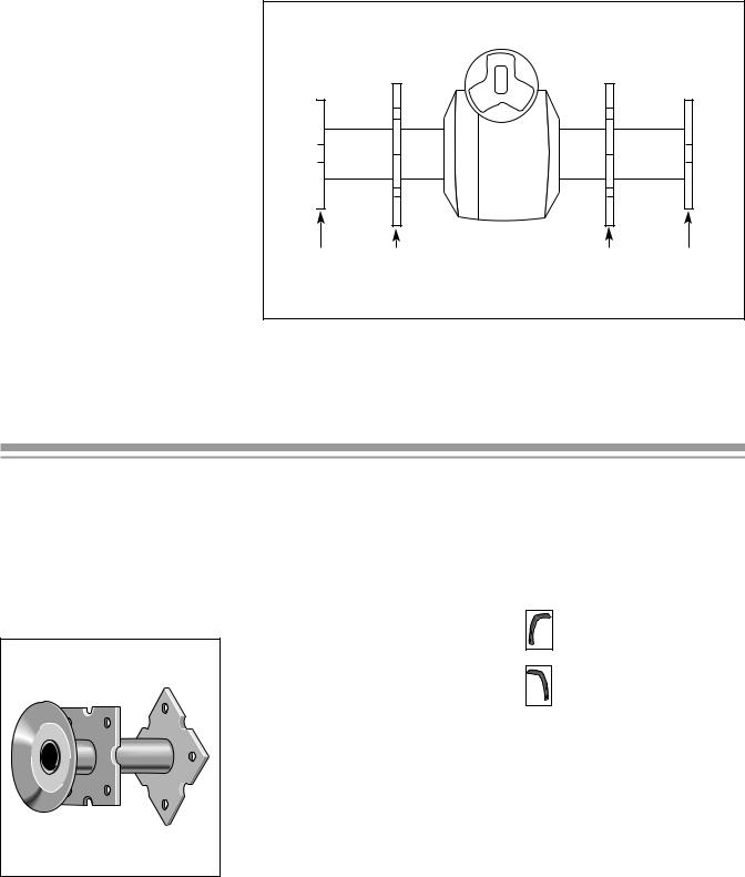
Horse Model tillers have two different style tine holders as shown in figures to the right:
Welded steel
Note: Welded steel holders may be secured to tine shaft either with two bolts and nuts or with single mounting bolt (illustrated in these instructions).
Cast iron
Owners of HORSE Model tillers with cast iron tine holders should keep the cardboard box in which this kit was shipped to use with the template (pattern) on the inside back cover of these instructions. You will use both the template and the box when assembling tines.
Owners of all other models can ignore the template and discard the box.
Welded Steel Tine Holder
Cast Iron Tine Holder
PRE-INSTALLATION STEPS
Step 1: Check Your Parts
Remove the tines and hardware package and check that you received all of the parts listed below for your model tiller. If any parts are missing or damaged, contact our Technical Service Department and we will arrange for replacements.
Item |
Qty |
Part # |
Description |
|
|
|
|
|
|
|
|
Horse, Econo Horse, |
8 |
GW-1270-1 |
Left-curved Tines |
and Pony Standard Tines |
8 |
GW-1270-2 |
Right-curved Tines |
|
|
|
|
Hardware for Standard |
16 |
1100043 |
3/8"-16 x 1-1/4" Hex Head Bolts (Grade 5) |
Tines (All Models) |
16 |
1733398 |
3/8"-16 Hex Locknuts |
Custom Tines |
8 |
GW-2475-1 |
Left-curved Custom Tines |
(All Models) |
8 |
GW-2475-2 |
Right-curved Custom Tines |
|
16 |
710-0514 |
3/8"-16 x 1-1/4" Hex Head Bolts (Grade 5) |
|
16 |
712-0798 |
3/8"-16 Hex Nuts |
|
16 |
736-0169 |
3/8" Lock Washers |
|
|
|
|
|
|
|
|
WARNING
To prevent serious personal injury when removing or installing your bolo tines:
•Stop the engine, and remove the electric start key (if your tiller features electric start).
•Let the engine and muffler area cool.
•Disconnect the spark plug wire, and position the wire away from the plug to prevent accidental starting.
CAUTION
Tine edges can be sharp and can have slivers that could cause personal injury. Use care at all times when handling tines. The tine hood edges may also be sharp. To prevent personal injury, wear thick gloves when touching the edges of the hood.
Step 2: Tine Removal
A.Carefully tilt the tiller forward until the engine is resting on the ground. (On some models it may be necessary to prop up the rear of the tiller or to add additional weight to the engine to stabilize the tiller in this position.)
B.Raise the tiller hood flap and secure it out of the way with a rubber band, string or, in the case of the PONY tiller, with the depth regulator adjustment bar knob.
C.Use two 9/16-inch wrenches
to remove the bolts which attach the tines to the holders. (Tines are not attached to cast iron holders with bolts. In the case of cast iron holders, remove each gang [set of four tines] from a holder by removing only one bolt, and then loosening the other three bolts on the same gang.)
D. Always discard old hardware and tines. Use only the hardware which came with your new tines.
If You Ordered Custom
Tines...
Custom tines (special, hardfaced tines which last up to 2- 1/2 times longer than standard tines) are perfect for tilling sandy, gritty soil, or for custom tilling or market gardening.
If you received Custom tines, read this General Information and then follow the standard tine installation instructions which apply to your particular model tiller.
If you have any difficulty installing your Custom tines, contact our Service Department (Refer to the back cover of this manual.)
Bolt Removal Tips
Loosen all four nuts on a holder plate or tine gang before trying to remove any of the nuts and bolts.
If necessary, use penetrating oil to loosen stubborn nuts.
If necessary, place the closed (boxed) end of a wrench on the nut and sharply tap the wrench with the rubber mallet until the nut is loose.
2
Step 3: Tine Identification
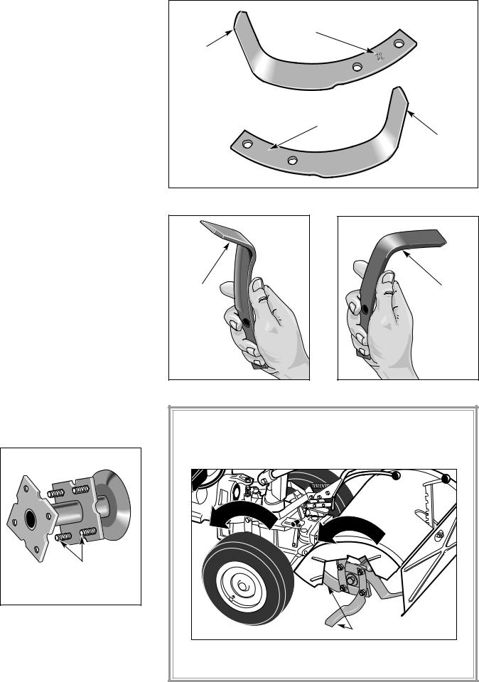
Separate the sixteen new tines into two groups: eight leftcurved tines and eight rightcurved tines. Tines can be identified as either left-curved or right-curved tines in two ways:
A.The letters and numbers stamped on the side of each tine are factory code marks which contain either an "L" (on leftcurved tines) or an "R" (on rightcurved tines). See Figure 1.
B.Or, hold the tine with the blunt edge toward you. If the tip curves toward the left, the tine is a left-curved tine. If the tip curves toward the right, the tine is a right-curved tine. See Figures 2 and 3 which show the two types of tines.
Step 4: Bolt Installation
NOTE: Skip this step if you have a HORSE Model tiller with cast iron tine holders.
A. On all other models, place the sixteen bolts through the holes in the tine holders with the threaded ends of the bolts pointing outward toward each side of the tiller as shown below in Figure 4. (The installation of tines on holders is described later in these instructions.)
Threaded |
Ends |
Figure 4: Insertion of bolts.
B. Sort lock washers and nuts into four groups of four each.
Look for "L" on
Left-curved Tine
Tip Pointing
Up
Look for "R" on
Right-curved Tine
|
Tip Pointing |
ER |
Up |
|
Figure 1: Look for "L" or "R" stamped on the tines.
Blunt |
Blunt |
|
Edge |
||
Edge |
||
|
Figure 2: Left-curved tine. |
Figure 3: Right-curved tine. |
IMPORTANT: Tines rotate in the same direction as the wheels. During the installation steps, place tines on holders so cutting edges (not the blunt, wider edges) will enter the soil
first when the tiller moves forward. See Figure 5.
|
el R |
|
|
|
|
|
|
|
|
e |
ot |
|
|
|
|
|
|
||
h |
|
|
at |
|
|
|
|
|
|
W |
|
|
|
i |
|
|
|
|
|
|
|
|
o |
|
|
|
|
|
|
|
|
|
|
n |
|
e R |
|
|
|
|
|
|
|
|
in |
ot |
|
||
|
|
|
|
|
T |
|
|
at |
|
|
|
|
|
|
|
|
|
|
i |
|
|
|
|
|
|
|
|
|
o |
|
|
|
|
|
|
|
|
|
n |
|
|
|
|
|
|
|
Cutting Edges |
||
Figure 5: Cutting edges of tines must enter the soil first when the tiller moves forward.
3
Step 5: Find the Installation Instructions for Your Model
Each tiller's distinctive tine pattern provides the optimum in tilling performance for that model. Be sure to install tines in the pattern described for your tiller. Find your tiller in the following list and go to the indicated page to continue with tine installation.
HORSE (Welded Steel Tine Holders), see the instructions at the bottom of this page.
HORSE (Cast Iron Tine Holders), see Page 8.
PONY, see Page 12.
ECONO HORSE, see Page 14.
Order of Installation
On all models, tines will be installed in the following order (see Figure 6):
A Left Inner Holder
B.Right Inner Holder
C.Left Outer Holder
D.Right Outer Holder
NOTE: When installing the tines you will be directed to perform a two step procedure and then check to ensure that the installation is correct before going on to the next step.
C |
A |
B |
D |
Figure 6: Order of installation on holders (welded steel holders shown).
HORSE MODEL TINE INSTALLATION
(WELDED STEEL HOLDERS)
Use this procedure to install tines only if your tine holders are shaped as shown below in Figure 7.
Figure 7: Welded steel tine holder.
NOTE: Be sure to use the specific tines (left or right curved) called for in each installation step.
Step 1: Position Holders
Before Starting Tine
Installation
On PTO Models, disengage the PTO Lever. On non-PTO Models, place the Forward/ Reverse Lever in Neutral.
Rotate the tine holders and shaft (by hand) until any one of the semi-circles on the outer mounting plates of the holders is at the 12 o'clock position in relation to the ground. See Figure 8 on Page 5.
Step 2: Install Tines on Left Inner Holder
Tines used in this step:
two right-curved tines
followed by
two left-curved tines
A. Place two right-curved tines (shown shaded in Figure 8) opposite each other on the previously installed bolts. Make sure that the tines are positioned as follows:
Tines are across from each other.
Tines are against the outer surface of the left inner holder plate.
4

Tips point inward toward the transmission housing.
The cutting edges will enter the soil first when the tiller moves forward.
B. Place two left-curved tines (unshaded in Figure 8) opposite each other on the bolts, overlapping the tines installed in Step 2-A. Make sure that the tines are positioned as follows:
These tines are also across from each other.
Tips point outward toward the sides of the tiller.
The cutting edges will enter the soil first when the tiller moves forward.
C. Add lock washers and nuts to all four bolts and tighten securely.
Step 3: Install Tines on Right Inner Holder
Tines used in this step:
two left-curved tines
followed by
two right-curved tines
A. Place two left-curved tines (shown shaded in Figure 8) opposite each other on the previously installed bolts. Make sure that the tines are positioned as follows:
The tips of these two tines should be directly opposite the tips of the two right-curved tines installed on the left inner holder in Step 2-A (see Figure 8).
Tines are against the outer surface of the right inner holder plate.
Tips point inward toward the transmission housing.
The cutting edges will enter the soil first when the tiller moves forward.
B. Place two right-curved tines (unshaded in Figure 8) opposite each other on the bolts, overlapping the tines installed in Step 3-A. Make sure that the tines are positioned as follows:
These tines are also across from each other.
Tips point outward toward the sides of the tiller.
The cutting edges will enter the soil first when the tiller moves forward.
C. Add lock washers and nuts to all four bolts and tighten securely.
Position SemiCircle at 12 o'clock
Left-curved
Tine
Tips of innermost tines are directly opposite from and point toward each other.
Right-curved
To allow an unobstructed view Tine of the left inner tine holder,
the left outer tine holder is not shown in this drawing.
Right-curved
Tine
Left -curved
Tine
Figure 8: Installing tines on inner holders.
5

Step 4: Check the Installation
This completes the installation of the tines on the two inner holders. To ensure that the installation is correct, check for the following:
A.Make sure that the tips of the four innermost tines (those nearest the transmission housing) are directly opposite each other, pointing toward each other and toward the transmission housing. See Figure 9.
B.Make sure that the cutting edges of all tines will enter the soil first when the tiller moves forward.
|
Innermost |
|
|
Tines |
|
Left outer holder |
Innermost |
|
Tines |
||
not shown. |
||
|
Figure 9: Innermost tines on inner holders.
Step 5: Install Tines on Left Outer Holder
Tines used in this step:
Two right-curved tines followed two left-curved tines
Left-curved |
Right-curved |
|
Tine |
||
Tine |
||
|
||
Position Semi- |
|
|
Circle at 12 o'clock |
|
Right-curved
Tine
Left-curved
Tine 
Tips of innermost tines are directly opposite from and point toward each other.
Tines on inner holders not shown.
Figure 10: Installing tines on outer holders.
6
 Loading...