


Professional Shop Manual
AC3 Series of 4-Cycle Engines
NOTE: These materials are for use by trained technicians who are experienced in the service and repair of outdoor power equipment of the kind described in this publication, and are not intended for use by untrained or inexperienced individuals. These materials are intended to provide supplemental information to assist the trained technician. Untrained or inexperienced individuals should seek the assistance of an experienced and trained professional. Read, understand, and follow all instructions and use common sense when working on power equipment. This includes the contents of the product’s Operators Manual, supplied with the equipment. No liability can be accepted for any inaccuracies or omission in this publication, although care has been taken to make it as complete and accurate as possible at the time of publication. However, due to the variety of outdoor power equipment and continuing product changes that occur over time, updates will be made to these instructions from time to time. Therefore, it may be necessary to obtain the latest materials before servicing or repairing a product. The company reserves the right to make changes at any time to this publication without prior notice and without incurring an obligation to make such changes to previously published versions. Instructions, photographs and illustrations used in this publication are for reference use only and may not depict actual model and component parts.
© Copyright 2010 MTD Products Inc. All Rights Reserved
Table of Contents
Chapter 1: Introduction ............................................................................................ |
1 |
Professional shop manual intent . . . . . . . . . . . . . . . . . . . . . . . . . . . . . . . . . . . . . |
1 |
Fasteners . . . . . . . . . . . . . . . . . . . . . . . . . . . . . . . . . . . . . . . . . . . . . . . . . . . . . . |
1 |
Assembly . . . . . . . . . . . . . . . . . . . . . . . . . . . . . . . . . . . . . . . . . . . . . . . . . . . . . . . |
2 |
Description . . . . . . . . . . . . . . . . . . . . . . . . . . . . . . . . . . . . . . . . . . . . . . . . . . . . . |
2 |
Identifying engines . . . . . . . . . . . . . . . . . . . . . . . . . . . . . . . . . . . . . . . . . . . . . . . |
2 |
Model and serial numbers . . . . . . . . . . . . . . . . . . . . . . . . . . . . . . . . . . . . . . . . . . |
4 |
Chapter 2: Maintenance ........................................................................................... |
5 |
Maintenance . . . . . . . . . . . . . . . . . . . . . . . . . . . . . . . . . . . . . . . . . . . . . . . . . . . . |
5 |
Oil . . . . . . . . . . . . . . . . . . . . . . . . . . . . . . . . . . . . . . . . . . . . . . . . . . . . . . . . . . . . |
5 |
Changing the oil . . . . . . . . . . . . . . . . . . . . . . . . . . . . . . . . . . . . . . . . . . . . . . . . . |
5 |
Spark plugs . . . . . . . . . . . . . . . . . . . . . . . . . . . . . . . . . . . . . . . . . . . . . . . . . . . . . |
6 |
Air filter . . . . . . . . . . . . . . . . . . . . . . . . . . . . . . . . . . . . . . . . . . . . . . . . . . . . . . . . |
7 |
Spark arrestor . . . . . . . . . . . . . . . . . . . . . . . . . . . . . . . . . . . . . . . . . . . . . . . . . . . |
8 |
Fuel filer . . . . . . . . . . . . . . . . . . . . . . . . . . . . . . . . . . . . . . . . . . . . . . . . . . . . . . . |
9 |
Valve lash . . . . . . . . . . . . . . . . . . . . . . . . . . . . . . . . . . . . . . . . . . . . . . . . . . . . . |
10 |
Chapter 3: Troubleshooting .................................................................................. |
11 |
Definitions . . . . . . . . . . . . . . . . . . . . . . . . . . . . . . . . . . . . . . . . . . . . . . . . . . . . . |
11 |
Introduction . . . . . . . . . . . . . . . . . . . . . . . . . . . . . . . . . . . . . . . . . . . . . . . . . . . . |
11 |
Steps to troubleshooting . . . . . . . . . . . . . . . . . . . . . . . . . . . . . . . . . . . . . . . . . . |
11 |
Identify factors that could cause the problem . . . . . . . . . . . . . . . . . . . . . . . . . . |
13 |
Repairing the problem . . . . . . . . . . . . . . . . . . . . . . . . . . . . . . . . . . . . . . . . . . . . |
17 |
Diagnostic tests . . . . . . . . . . . . . . . . . . . . . . . . . . . . . . . . . . . . . . . . . . . . . . . . . |
17 |
Prime test . . . . . . . . . . . . . . . . . . . . . . . . . . . . . . . . . . . . . . . . . . . . . . . . . . . . . |
18 |
Compression testing . . . . . . . . . . . . . . . . . . . . . . . . . . . . . . . . . . . . . . . . . . . . . |
19 |
Chapter 4: Ignition ................................................................................................. |
21 |
Troubleshooting the Ignition System . . . . . . . . . . . . . . . . . . . . . . . . . . . . . . . . . |
21 |
Testing the module . . . . . . . . . . . . . . . . . . . . . . . . . . . . . . . . . . . . . . . . . . . . . . |
22 |
Test the engine stop switch . . . . . . . . . . . . . . . . . . . . . . . . . . . . . . . . . . . . . . . . |
23 |
Module . . . . . . . . . . . . . . . . . . . . . . . . . . . . . . . . . . . . . . . . . . . . . . . . . . . . . . . |
24 |
Flywheel . . . . . . . . . . . . . . . . . . . . . . . . . . . . . . . . . . . . . . . . . . . . . . . . . . . . . . |
25 |
Chapter 5: Fuel system and carburetor ............................................................... |
27 |
Inspecting the fuel: . . . . . . . . . . . . . . . . . . . . . . . . . . . . . . . . . . . . . . . . . . . . . . |
28 |
Test fuel for alcohol . . . . . . . . . . . . . . . . . . . . . . . . . . . . . . . . . . . . . . . . . . . . . . |
28 |
Fuel tank . . . . . . . . . . . . . . . . . . . . . . . . . . . . . . . . . . . . . . . . . . . . . . . . . . . . . . |
30 |
Fuel lines . . . . . . . . . . . . . . . . . . . . . . . . . . . . . . . . . . . . . . . . . . . . . . . . . . . . . . |
31 |
Carburetor . . . . . . . . . . . . . . . . . . . . . . . . . . . . . . . . . . . . . . . . . . . . . . . . . . . . . |
32 |
Troubleshooting the carburetor . . . . . . . . . . . . . . . . . . . . . . . . . . . . . . . . . . . . . |
35 |
Disassembly of the carburetor . . . . . . . . . . . . . . . . . . . . . . . . . . . . . . . . . . . . . . |
37 |
Re-assembly of the carburetor . . . . . . . . . . . . . . . . . . . . . . . . . . . . . . . . . . . . . |
39 |
Carburetor insulator . . . . . . . . . . . . . . . . . . . . . . . . . . . . . . . . . . . . . . . . . . . . . |
41 |
I
Chapter 6: Starters ................................................................................................. |
43 |
Recoil Starter Removal . . . . . . . . . . . . . . . . . . . . . . . . . . . . . . . . . . . . . . . . . . . |
43 |
The starter rope, pulley and springs . . . . . . . . . . . . . . . . . . . . . . . . . . . . . . . . . |
44 |
Electric starter system . . . . . . . . . . . . . . . . . . . . . . . . . . . . . . . . . . . . . . . . . . . . |
48 |
Chapter 7: Clutch and Upper Drive Shaft ............................................................ |
49 |
Upper drive shaft assembly . . . . . . . . . . . . . . . . . . . . . . . . . . . . . . . . . . . . . . . . |
49 |
Clutch Removal/replacement . . . . . . . . . . . . . . . . . . . . . . . . . . . . . . . . . . . . . . . |
51 |
Chapter 8: Engine assembly .................................................................................. |
53 |
Engine disassembly . . . . . . . . . . . . . . . . . . . . . . . . . . . . . . . . . . . . . . . . . . . . . |
54 |
Engine Reassembly . . . . . . . . . . . . . . . . . . . . . . . . . . . . . . . . . . . . . . . . . . . . . |
59 |
II

Introduction
CHAPTER 1: INTRODUCTION
Professional Shop Manual intent
This Manual is intended to provide service dealers with an introduction to the mechanical aspects of the AC3 series of 4-cycle engines.
Disclaimer: The information contained in this manual is correct at the time of writing. Both the product and the information about the product are subject to change without notice.
About the text format:
NOTE: is used to point out information that is relevant to the procedure, but does not fit as a step in the procedure.
•Bullet points: indicate sub-steps or points.
|
|
|
|
|
|
|
|
|
|
Caution is used to point out potential danger to the technician, operator, bystanders, or sur- |
|
|
|
! CAUTION |
|
||
|
|
|
rounding property. |
|
|
|
|
|
|
|
|
|
|
|
|
|
|
|
|
|
|
|
|
|
|
|
|
|
|
|
|
|
|
Warning indicates a potentially hazardous situation that, if not avoided, could result in death |
|
|
|
! WARNING |
|
||
|
|
|
or serious injury. |
|
|
|
|
|
|
|
|
|
|
|
|
|
|
|
|
|
|
|
|
|
|
|
|
|
|
|
|
|
|
Danger indicates an imminently hazardous situation that, if not avoided, will result in death or |
|
|
|
! DANGER |
|
||
|
|
|
serious injury. This signal word is to be limited to the most extreme situations |
|
|
|
|
|
|
|
|
|
|
|
|
|
|
Disclaimer: This manual is intended for use by trained, professional technicians.
•Common sense in operation and safety is assumed.
•In no event shall MTD be liable for poor text interpretation or poor execution of the procedures described in the text.
•If the person using this manual is uncomfortable with any procedures they encounter, they should seek the help of a qualified technician or MTD Technical Support.
Fasteners
•Most of the fasteners used on the engine are metric. Some are sized in fractional inches. For this reason, wrench sizes are frequently identified in the text, and measurements are given in U.S. and metric scales.
•If a fastener has a locking feature that has worn, replace the fastener or apply a small amount of releasable thread locking compound such as Loctite® 242 (blue).
•Some fasteners like cotter pins are single-use items that are not to be reused. Other fasteners such as lock washers, retaining rings, and internal cotter pins (hairpin clips) may be reused if the do not show signs of wear or damage. This manual leaves that decision to the judgement of the technician.
1
AC3 Series of engines
Assembly
Torque specifications may be noted in the text that covers assembly, they may also be summarized in tables along with special instructions regarding locking or lubrication. Whichever method is more appropriate will be used. In many cases, both will be used so that the manual is handy as a quick-reference guide as well as a step-by-step procedure guide that does not require the user to hunt for information.
The level of assembly instructions provided will be determined by the complexity and of reassembly, and by the potential for unsafe conditions to arise from mistakes made in assembly.
Some instructions may refer to other parts of the manual for subsidiary procedures. This avoids repeating the same procedure two or three times in the manual.
Description
The AC3 engine is used on a variety of handheld equipment. This engine has:
•29cc’s of displacement.
•A cantilever crank design.
•Pushrod activated OHV.
• Genuine 4-cycle design, not a hybrid 2-cycle/4- cycle like Stihl and Shindaiwa.
•Engine covers split front and back.
Currently there are engine models in this series of |
AC3 engine |
|
engine: |
|
|
|
|
|
• |
AC3 |
|
• |
AC3.1 |
Figure 1.1 |
|
|
|
•AC3.2
The AC3 version has an 8 to 1 compression ratio. The AC3.1 and the AC3.2 have a 9 to 1 compression ratio which increased power approximately 20%. The AC3.1 and 3.2 engines are also available with electric start versions.
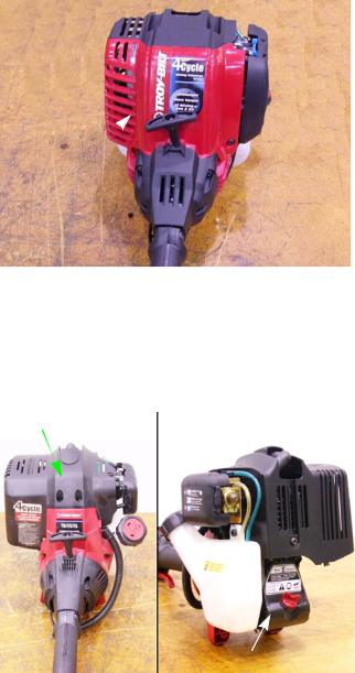
Identifying engines
AC2 |
|
Full engine cover |
|
• |
26 cc’s of displacement. |
|
• |
Engine cover surrounds the cylinder head and |
|
|
muffler. |
Visible from the rear:
•A plastic, diagonal split crankcase sump.
•A dip stick that threads into the sump.
Plastic sump
Figure 1.2
2
Introduction
AC3
Engine cover splits front to back
•29cc’s of displacement.
•Engine covers split front and back.
•Metal sump
Figure 1.3
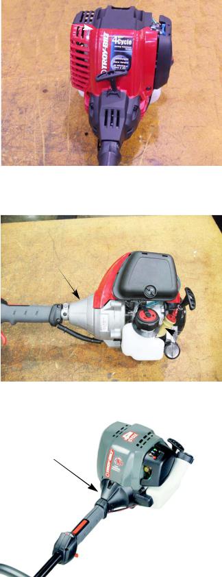
AC4
• 32 cc’s of displacement.
• Aluminum clutch housing.
Aluminum clutch housing
• Extended oil fill tube that is near the carburetor.
• End mounted recoil starter.
 oil
oil
fill tube
Figure 1.4
Plastic clutch housing
AC5
•25 cc’s of displacement.
•Identical to the AC4 except for the plastic clutch housing.
Figure 1.5
3

AC3 Series of engines
Model and Serial Numbers
The model (item) and serial number are on a little white sticker with bar code. These are the numbers needed when ordering parts. This sticker can be found on the side of the engine.
Serial number
Model number
Figure 1.6
The model number is 41ADT59C711. The break down of what the number mean is as follows:
41 ............................................................................................ |
Hand held product |
........A...................................................................................... |
Sales level |
........... D.................................................................................. |
Product type |
.................T59 ......................................................................... |
Unique Identifier |
.........................C..................................................................... |
Packaging code |
.............................711.............................................................. |
Customer number |
The serial number is 1F296DZ0060. The serial number reads as follows:
1 .............................................................................................. |
Engineering level |
..F ............................................................................................ |
Month of production (F = June) |
.....29 ....................................................................................... |
Day of the month |
.........6 ..................................................................................... |
Last digit of the year |
...........D................................................................................... |
Plant it was built in (MTD Southwest) |
..............Z ................................................................................ |
Assembly line number |
.................0060 ....................................................................... |
Number of unit built |
4
Maintenance
CHAPTER 2: MAINTENANCE
MAINTENANCE
The information in this manual applies to the AC3 series of engines. Some basic principles may apply to engines produced by other manufacturers.
As the saying goes “an ounce of prevention is worth a pound of cure”. The same can be said about preventive maintenance on outdoor power equipment. By changing the spark plug, air filter, and oil at recommended intervals many failures can be avoided. Sometimes just clearing off yard debris that has collected through use can make the difference between a properly running piece of equipment and the expensive inconvenience of unplanned repairs.
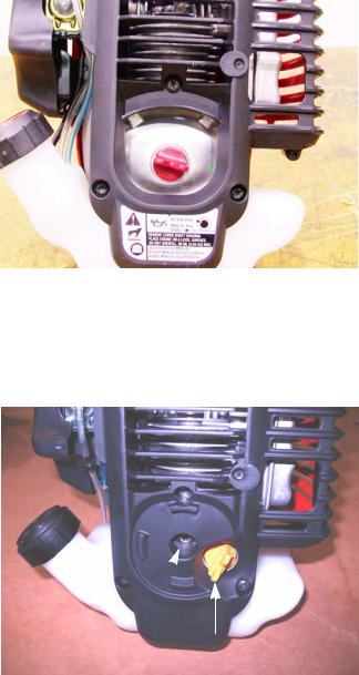
Oil

 Oil plug
To check the oil:
1.Clean around the oil plug.
2.Place the trimmer on a level surface.
3.Unscrew the oil plug. See Figure 2.1.
4.The oil should be level with the bottom of the threads.
NOTE: If needed, add oil slowly until oil level is even with the bottom of the threads.
5.Tighten oil plug finger tight.
Figure 2.1
Changing the oil
The first oil change should be done at 10 hours and then it should be changed every 25 hours or at the start of the season.
Electric start Oil plug coupler
To change the oil:
1.Clean around the oil plug.
2.Remove the oil plug. See Figure 2.2.
3.Tip the trimmer to the side and drain the oil in a safe, approved container.
4.Disposed of the used oil by following the federal, state and local regulations.
5.Fill the engine with 3.04 fluid ounces (90 ml) of SAE 30 oil that meets or exceeds API SM standards.
NOTE: The spark arrestor should be cleaned and the valves adjusted at every oil change.
Figure 2.2
5

AC3 Series of engines
Spark plugs
The spark plug used in the 32cc trimmer is a Champion RDZ19H gapped to 0.025” (.655 mm).
See Figure 2.3.
Wear rate will vary with severity of use. If the edges of the center electrode are rounded-off, or any other apparent wear / damage occurs, replace the spark plug before operating failure (no start) occurs.
Cleaning the spark plug:
NOTE: We do not recommend cleaning spark plugs.
•Use of a wire brush may leave metal deposits on the insulator that causes the spark plug to short out and fail to spark.
• Use of abrasive blast for cleaning may cause |
Figure 2.3 |
damage to ceramic insulator or leave blast |
|
media in the recesses of the spark plug. |
|
•When the media comes loose during engine operation, severe and non-warrantable engine damage may result.
Inspection of the spark plug can provide indications of the operating condition of the engine.
•Light tan colored deposits on insulator and electrodes is normal.
•Dry, black deposits on the insulator and electrodes indicate an over-rich fuel / air mixture (too much fuel or not enough air)
•Wet, black deposits on the insulator and electrodes indicate the presence of oil in the combustion chamber.
•Heat damaged (melted electrodes / cracked insulator / metal transfer deposits) may indicate detonation.
•A spark plug that is wet with fuel indicates that fuel is present in the combustion chamber, but it is not being ignited.
Spark plug removal and installation |
Spark plug wire |
To replace a spark plug: |
|
1.Disconnect the spark plug wire. See Figure 2.4.
Do not grab the spark plug wire with pliers. Damage to the sparkplug boot will result. A damaged
spark plug boot will weaken the spark of the spark plug.
2.Remove the spark plug using a 5/8” spark plug socket.
3.Gap a new plug at 0.025” (.6 mm).
4. Install the spark plug and tighten to a torque of 100 - Figure 2.4 110 in. lbs.(11 -12 Nm).
5.Follow steps 1 and 2 in reverse order.
6.Test run the trimmer in a safe area before returning it to service.
6
Maintenance
Air filter
A dirty air filter can reduce engine power, increase fuel consumption, increase CO emissions and make starting more difficult.
The air filter should be cleaned every 10 hours of use (depending on area of use, dusty areas require more frequent cleanings).
Air filter cover
Press tab
Figure 2.5

 Air filter
Figure 2.6
To clean/replace the air filter:
1.Remove the air filter cover by pressing in the tab on the bottom of the filter housing and lifting the cover off. See Figure 2.5.
2.Pull the filter out. See Figure 2.6.
3.If the filter is crumbling or brittle, replace the filter.
4.Wash the air filter with warm soapy water. Let the filter air dry. DO NOT wring the filter out.
NOTE: Wringing the filter can tear it. Squeeze the filter, but do not twist it.
5.Put a 1/4 teaspoon (1.25cc) of oil to the filter and squeeze it through out the filter.
6.Insert the filter into air filter housing.
7.Install the air filter cover.
8.Test run the engine before returning it to service
7

AC3 Series of engines
Spark arrestor
The spark arrestor should be checked and/or cleaned every 25 hours of use.
NOTE: The spark arrestor also serves to keep blockages out of the exhaust system. Typical blockages include insect nests built during the dormant season.
NOTE: A spark arrestor is required by law when trimmer are used near “unimproved” land.
To check/clean the spark arrestor:
1.To clean the spark arrestor remove the engine cover using a T-20 driver. See Figure 2.7.
2.Remove the two screws holding the spark arrestor cover in place with a T-25 driver. See Figure 2.8.
3.Inspect the spark arrestor. See Figure 2.9.
4.If it is blocked with carbon, remove it. It may be:
•Replaced
•Cleaned by mechanical means
•Solvent cleaned
•Burned clean using a butane or propane torch.
5.Reinstall the Spark arrestor screen By following the previous steps in reverse order.
NOTE: Apply a thread locking compound such as
Loctite® 266TM to the long bolt (the one with a hex head, it is the one closest to the other two hex head screws) and torque it to 50-55 in. lbs. (5.7-6.2 Nm). Hand tighten the short screw.
Engine cover
Screws
Figure 2.7
Screws for spark arrester
Figure 2.8
Spark arrestor screen
Figure 2.9
8
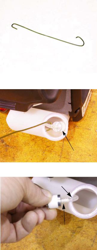
Fuel filer
Figure 2.10
Fuel filter
Figure 2.11
Fuel line
Nipple
Figure 2.12
Maintenance
A dirty fuel filter can result in a lean run condition. The fuel filter should be replaced every 25 hours of use.
NOTE: The weighted fuel filter (clunk) keeps the filter submerged in the fuel at any angle of operation. The filter removes dirt and air bubbles from the fuel. Running the trimmer without the filter may allow air into the fuel line creating a lean run condition at higher RPMs. This will cause a catastrophic failure of the engine.
To replace the fuel filter:
1.Bend a piece of wire to make a hook. See Figure 2.10.
2.Remove the gas cap.
3.Stick the hook end of the wire into the fuel tank and fish out the fuel filter. See Figure 2.11.
4.Carefully remove the fuel line from the barb on the fuel filter. Clean or discard the old fuel filter.
See Figure 2.12.
5.Inspect the fuel lines. Replace them if they are cracked.
6.Install a new filter by following the previous steps in reverse order.
7.Test run the engine before returning it to service.
9
AC3 Series of engines
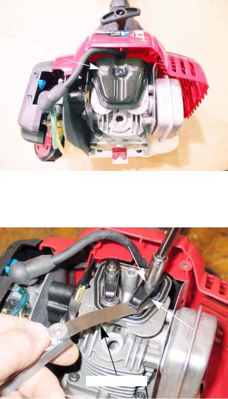
Valve lash
To adjust the valves:
NOTE: Loose valve lash on these engines can mimic the symptoms of a lean fuel/air mix-
ture.
Valve cover
1. Remove the engine cover and spark plug, following the steps described in the previous sections of this chapter.
2.Remove the valve cover using a T-25 driver. See Figure 2.13.
3.Rotate the crankshaft to bring the piston to top dead center of the compression stroke (valves closed).
NOTE: Use a probe in the spark plug hole to track the piston position.
NOTE: The valve clearance for this engine is 0.003”-.006”(.08-.15 mm) for both valves.
4.Check the valve lash by inserting a feeler gauge between the rocker arm and the valve stem. To adjust the valve, loosen or tighten the fulcrum nut with a 8mm wrench until there is a slight drag on the feeler gauge. See Figure 2.14.
5.Inspect the valve cover gasket for damage. If it is damaged or compressed, replace it.
6.Reassemble the trimmer by following steps 1 and 2 in reverse order.
7.Test run the engine in a safe area before returning it to service.
Figure 2.13
Fulcrum nut
Rocker
Feeler gauge
Figure 2.14
10

Troubleshooting
CHAPTER 3: TROUBLESHOOTING
Definitions
Troubleshooting - The act of gathering information by preforming tests and direct observations. Diagnosis - A theory of what the problem is, based on the information gathered by troubleshooting.
Introduction
Diagnosing an engine is an art form that is built on several factors. First and most importantly is a good understanding of how the engine works. The second is a skill set that has been honed by experience. Finally the use of visual observations and a structured, systematic approach to troubleshooting a problem.
The first part of this chapter will outline the steps of troubleshooting an engine so a technician can form a proper diagnosis. The second half of this chapter will describe specific procedures and tests to preform while troubleshooting.
The first two rules in troubleshooting are to cause no further harm to the engine and to pre-
! CAUTION vent injuries. Always check the oil level and condition before starting an engine. Check attachments for damage and make sure they are firmly mounted.
Steps to troubleshooting
NOTE: The steps and the order of the steps that follow are a suggested approach to troubleshooting the trimmer engine. The technician does not necessarily have to follow them as described in this chapter
Define the problem
The first step in troubleshooting is to define the problem:
1.Crankshaft will not turn.
•Hard to pull rope, steady pressure
•Rope jerks back
•Rope will not pull at all
2.Crankshaft turns, no start
3.Starts, runs poorly
•Starts, then dies
•Runs with low power out put
•Makes unusual smoke when running I. Black smoke, usually heavy
II.White smoke, usually heavy
III.Blue smoke. usually light
•Makes unusual sounds when running
I.Knock
II.Click
III.Chirp
IV. Unusual exhaust tone
11
AC3 Series of Engines
There are tools that the technician can use in order to define the problem, such as:
1.Interview the customer.
•Get a good description of their complaint.
•If it is an intermittent problem, verify what conditions aggravates the problem as best as possible.
•Get an accurate service history of the equipment.
•Find out how the customer uses and stores the equipment.
2.Direct observation:
•Do not take it that the customer is correct with their description of the problem. Try to duplicate the problem.
•Check the general condition of the equipment (visually).
I. Cleanliness of the equipment will indicate the level of care the equipment has received.
II.Make sure the engine and attachments are securely fastened.
III.The tune-up factors.
NOTE: Most hard starting and poor running conditions can be solved by preforming a tune-up.
a.Check the condition and amount of oil in the crankcase.
b.Check the level and condition of the fuel.
c.Check the air filter and look for signs of dirt ingestion.
d.Check the ignition and “read” the spark plug.
e.Look for obvious signs of physical damage, bent blade, exhaust system blockage or cooling system blockage.
6.Broken starter rope.
•Usually means the engine was hard to start.
•Makes it impossible to confirm any running or hard starting symptoms by direct observation.
•Some inference can be made from checking other factors of the general condition of the equipment.
12
Troubleshooting
Identify factors that could cause the problem
This is the second step in the troubleshooting process.
1.Crankshaft will not turn.
•Hard to pull rope, steady pressure - This usually indicates a mechanical bind of some sort. the likely suspects are:
II.A parasitic load from a jammed attachment or drive shaft.
III.An internal drag from a scored or seized piston.
•Rope jerks back - This usually indicates that the piston is stopping before top dead center on the compression stroke and is being driven back down by compression or combustion. The likely suspects are:
I.Compression that is unusually high.
a.valve lash.
b.a partial hydraulic lock.
III.Ignition timing is advanced.
a.Improper air gap.
b.Sheared or missing flywheel key.
c.The wrong flywheel or module is installed on the engine.
•Rope will not pull at all -This is usually either a quick fix or a catastrophic failure. The likely suspects are:
I.A broken starter recoil (easy fix).
II.Complete hydraulic lock (easy fix).
III.External binding/jammed attachment (easy fix).
IV. Internal binding, crankshaft, connecting rod or piston (unrepairable)
5.Crankshaft turns, no start.
•Most gasoline engine diagnosis involves isolating problems in the four critical factors an engine needs to run properly:
I.Ignition- sufficient spark to start combustion in the cylinder, occurring at the proper time.
II.Compression- enough pressure in the cylinder to convert combustion into kinetic motion. It also needs sufficient sealing to generate the vacuum needed to draw in and atomize the next intake charge.
III.Fuel- correct type and grade of fresh gasoline; in sufficient quantity, atomized (tiny droplets) and in correct fuel/air proportions.
IV. Flow- if all of the above conditions are met, but the flow of air is constricted on the inlet or exhaust side it will cause the engine to run poorly or not at all. This also includes ensuring the valves are timed to open at the proper time.
•Isolate the ignition system and compression from the fuel system by preforming a prime test.
I.Burns prime and dies. This would indicate a fuel system issue.
II.Does not burn prime. Not a fuel system issue. Check for an ignition, compression or flow problem.
13
AC3 Series of Engines
•Compression or ignition problem
I. Check the engine stop and/or ignition switch.
II.Test the ignition system using a proper tester.
III. Replace the spark plug with a new one or a known good one.
IV. Check compression.
V.Check valve lash.
VI. Check valve timing/actuation.
VII. Check exhaust.
8.Starts, runs poorly
•Starts, then dies
I.Run the engine with a spark tester in-line between the spark plug wire and the spark plug or use an oscilloscope and see if the spark goes away at the same time the engine dies.
II.Check choke operation.
a.Black smoke?
b.Wet plug?
III. Test for invisible damage to the air filter by starting the engine with the air filter removed.
IV. Prime test immediately after engine dies. If it restarts; this may indicate a problem with fuel flow to the carburetor. Check the gas cap, fuel line, fuel filter, and the carburetor.
•Runs with low power output.
I.Look for unusual exhaust color (smoke).
II.Unusually hot muffler (may glow red).
a.Retarded ignition
b.Exhaust valve opening early (lash too tight)
III.Mechanical bind
a.A loose ignition module can drag on the flywheel or lock it up.
b.Parasitic external load. A bind in the equipment the engine is powering.
c.Internal drag from a scored piston or similar damage.
IV. Low compression
a.Check valve lash
b.Check compression III. Flow blockage
a.Exhaust blockage, usually accompanied by an unusual exhaust sound.
NOTE: Just as a throttle on the carburetor controls the engine RPMs by limiting the amount of air an engine can breathe in, an exhaust blockage will limit engine performance by constricting the other end of the system.
14
Troubleshooting
II.The muffler itself my be blocked.
III.The spark arrestor may be blocked.
IV. The exhaust valve may not be opening fully, possibly because of extremely loose valve lash settings.
V.The exhaust valve seat may have come loose in the cylinder head. This may cause a loss of compression, a flow blockage or it may randomly alternate between the two.
NOTE: The cause of an exhaust valve seat coming loose is usually over-heating.
VI. Intake blockage
a.An intake blockage up-stream of the carburetor will cause a rich fuel/air mixture and constrict the amount of air that the engine can draw in, limiting performance. A blocked air filter is a common cause of this.
b.An intake valve that does not open fully will cause a blockage. A possible cause of this is loose valve lash.
VII. Makes unusual smoke when running
a.Black smoke, usually heavy usually indicates a rich air fuel mixture
•Not enough air: air filter blockage or a partially closed choke.
•Too much fuel: needle valve stuck or metering / emulsion issues with the carburetor.
b.White smoke, usually heavy
•Oil in muffler, usually the result of improper tipping. the engine will “fog” for a minute or so, then clear-up on its own.
•Oil that is diluted with gasoline. It may be caused by improper tipping. It can also be caused by leaky carburetor needle valve, if there is a down-hill path from the carburetor to the intake port. Check oil for gasoline smell, repair carburetor.
c.Blue smoke, usually light.
VIII. PCV system
a.May be blocked or unplugged.
b.May be over-come by massive over-filling or oil dilution with gasoline.
c.Will cause oil to exit the engine via any low-resistance paths.
IX. Piston rings
a.Confirm with leak-down test.
b.Smoke will be more pronounced under load.
c.Repair may not make economic sense. X. Valve guides (and intake valve stem seal).
a.Smoke will be more pronounced on over-run.
b.Makes unusual noise when running.
15
AC3 Series of Engines
•Knock
*Check for loose mounting of engine or driven implement
*Rotate crankshaft back-and-forth to check for loose connecting rod.
•Click
*Half-engine speed clatter: loose valve lash.
*Half-engine speed clatter, slightly heavier: wrist-pin.
*Rhythmic heavy-light engine speed click: piston slap
•Spark-knock
*Advanced ignition timing
*Low octane fuel
*Over-heating engine (check for blocked cooling air flow)
*Carbon build-up in cylinder: glowing carbon chunks pre-igniting air fuel mix. XI. Unusual exhaust tone
a.Splashy, blatty, wheezing or whistling.
•Splashy or blatty idle usually indicates a slightly rich condition.
•Whistling or wheezing may indicate an exhaust blockage, usually slightly muffled.
•Backfire
*On over-run: unburned fuel igniting past exhaust valve. Mixture not burning completely in combustion chamber. It may be too rich or it may be a spark plug or an ignition problem.
•Skip
*Usually ignition related.
*Run the engine with a spark tester in-line between the spark plug wire and the spark plug or use an oscilloscope and see if the spark goes away at the same time the engine dies.
XII. Engine RPMs surge (hunting)
a.Lean Air-fuel mixture conditionWhen AFR (Air Fuel Ratio) is significantly below stoichiometric ratio (14.7:1) engine RPMs sink until they reach a point that can be supported by the available fuel. This causes a momentary surge in power until the available fuel is consumed, then the RPMs fall again, repeating the cycle.
•Too much air: look for an air leak in the intake tract
•Not enough fuel: look for fuel supply or carburetor problems
16
Troubleshooting
Repairing the problem
The third step in the diagnostic process is to repair the problem. This step consists of:
1.Form a diagnosis by using all of the information gathered from the troubleshooting that was performed.
2.Physically perform the repair.
The fourth, and hopefully final, step in the troubleshooting process is the follow through. This step consists of:
1.Thoroughly test the repaired equipment: confirming that the initial diagnosis was correct. If it was wrong, start the troubleshooting process over again.
NOTE: Sometimes the engine will have multiple problems at the same time. By performing one repair, other issues may show up that are unrelated to the first repair.
2.Delivery to customer: We are not just repairing equipment, we are repairing customers.
•Inoculate against recurring problem with education, e.g.... if the problem was caused by stale fuel, make sure the customer is aware that fuel goes bad over time.
•Make sure the customer understands the repair, preventing “superstitious” come-backs.
Diagnostic tests
When troubleshooting an engine, the diagnostic tests are done in a specific order. The order is:
1.Compression testing
2.Ignition testing
3.Carburetor/fuel system testing.
NOTE: A prime test is a handy short cut. It will test compression and ignition in a single step. If the engine will start from a prime test, the problem is in the fuel system. If the engine will not start with the prime, the compression and ignition tests will need to be performed.
17
 Loading...