


T / 120
MTD Products Aktiengesellschaft • Saarbrücken • Germany |
A |
Part No: 769-01620 1/05 |

GB |
|
|
F |
• MANUEL DE L’UTILISATEUR . . . . . . . . . . . . . . . . . . . |
21 |
D |
• GEBRAUCHSANLEITUNG . . . . . . . . . . . . . . . . . . . . . |
31 |
I |
• MANUALE PER L'UTENTE . . . . . . . . . . . . . . . . . . . . . |
41 |
P |
• MANUAL DO UTILIZADOR . . . . . . . . . . . . . . . . . . . . |
51 |
E |
• MANUAL DE INSTRUCCIONES DEL USUARIO . . . . 61 |
|
2
8
2
3
4
5
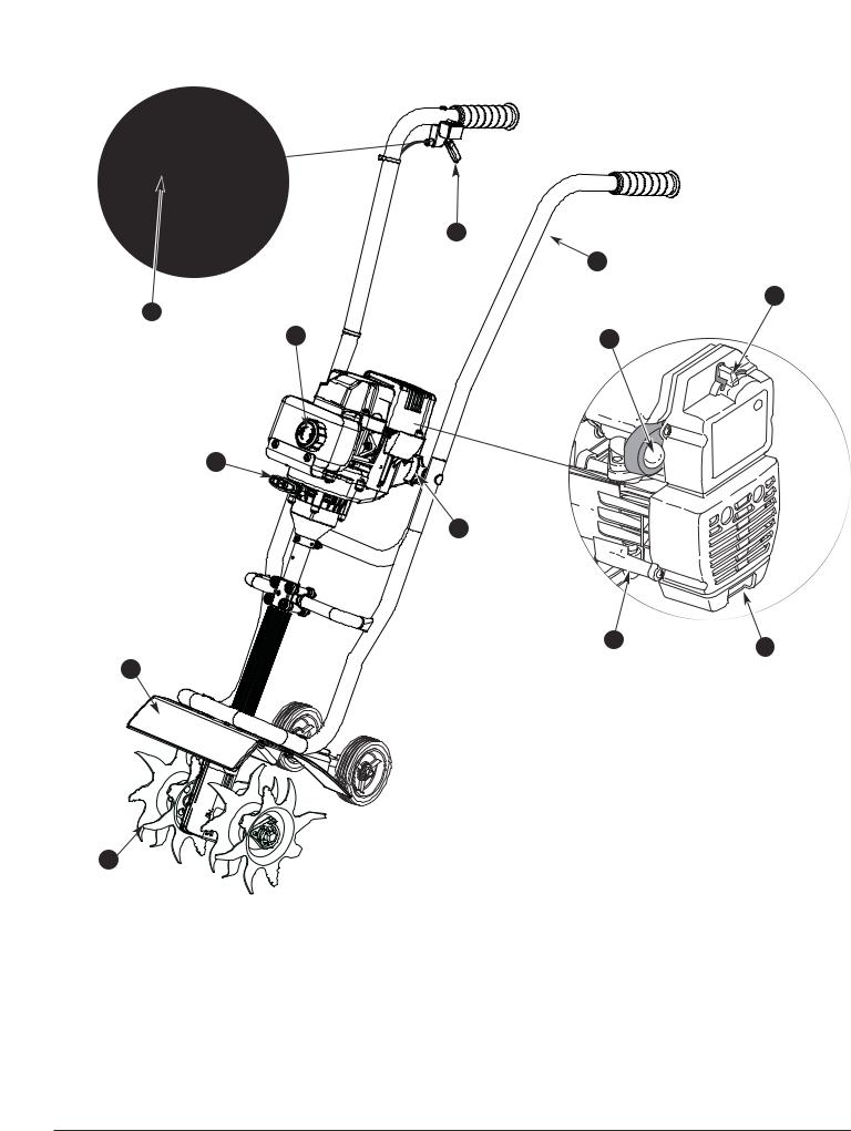
Description of Parts |
|
|
|
1. |
Muffler |
7. |
Spark Plug |
2. |
Fuel Cap |
8. |
Ignition Switch |
3. |
Starter Rope Grip |
9. |
Throttle Trigger |
4. |
Tine Guard |
10. |
Handlebar |
5. |
Tines |
11. |
Handlebar Knob |
6. |
Primer |
12. Choke Lever |
|
9
12
6
11
7
1
KNOW YOUR
FAMILIARISEZ-VOUS AVEC L’APPAREIL
LERNEN SIE |
GERÄT KENNEN |
PANORAMICA SULL’UNITÀ |
|
FAMILIARIZE |
COM A SUA MÁQUINA |
CONOZCA SU UNIDAD
Description des
1.Pot d’échappement
2.Bouchon du carburant
3.Poignée de la corde de démarrage
4.Protecteur des
5.Dents
6.Amorceur
7.Bougie
8.Contact d'allumage
9.Manette des gaz
10.Poignée
11.Bouton de guidon
12.Levier d'étrangleur
3

Beschreibung der Teile
1.Schalldämpfer
2.Tankverschluß
3.Starterleinengriff
4.Zinkenschutz
5.Blatt
6.Einspritzvorrichtung
7.Zündkerze
8.Zündschalter
9.Gashebel
10.Griffstange
11.Lenkstangenknopf
12.Chokehebel
Descrizione dei componenti
1.Marmitta
2.Tappo serbatoio
3.Avvio a strappo
4.Protezione punte
5.Lama
6.Innesco
7.Vela
8.Interruttore di accensione
9.Leva acceleratore
10.Impugnatura
11.Manopola del manubrio
12.Leva starter
Descrição das peças
1.Silenciador
2.Tampão do depósito de combustível
3.Pega da corda de arranque
4.Resguardo dos Dente
5.Forquilhas
6.Iniciador
7.Candela
8.Interruptor da ignição
9.Gatilho do acelerador
10.Guiador
11.Puxador do guiador
12.Posição de operação
Descripción de las piezas
1.Silenciador
2.Tapa del combustible
3.Mango de la cuerda de arranque
4.Protección de las púas
5.Dientes
6.Cebador
7.Bujía
8.Interruptor de encendido
9.Gatillo del regulador
10.Barra de la manija
11.Perilla de la agarradera
12.Palanca del obturador
4
1 |
1 |
Fig. 1
|
2 |
3 |
1 |
|
4 |
5 |
Fig. 3
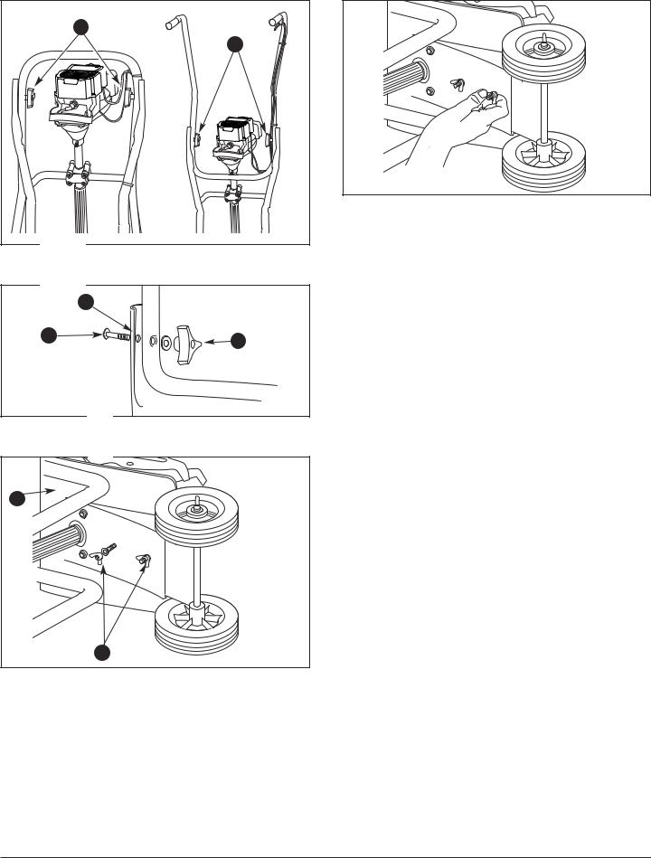
Description of Parts – Figs. 1-4 |
|
|
|
1. |
Handlebar Knob |
4. |
Tine Guard |
2. |
Hole |
5. |
Wing Nuts & Lock |
3. |
Bolt |
|
Washers |
Fig. 4
Description des pièces – Fig. 1-4 |
|
|||
1. |
Bouton de guidon |
4. |
Protecteur des |
|
2. |
Trou |
|
dents |
|
5. |
Écrou papillon et |
|||
3. |
Boulon |
|||
|
rondelle de blocage |
|||
|
|
|
||
Beschreibung der Teile – Abb. 1-4 |
|
|||
1. |
Lenkstangenknopf |
5. |
Flügelmutter & |
|
2. |
Loch |
|
Federring |
|
|
|
|||
3.Bolzen
4.Zinkenschutz
Descrizione dei componenti – figg. 1-4
1. |
Manopola del manubrio |
4. |
Protezione punte |
|
|
||
2. |
Buco |
5. |
Galletto e |
|
rosetta di protezione |
||
3. |
Bullone |
|
|
|
|
||
Descrição das peças – Figuras 1-4 |
|||
1. |
Puxador do guiador |
|
4. Resguardo dos |
2. |
Orifício |
|
Dentes |
|
5. Porca de Orelhas e |
||
3. |
Perno |
|
|
|
Anilha de Retenção |
||
|
|
|
|
Descripción de las piezas – Fig. 1-4
1. |
Perilla de la agarradera |
4. |
Protección de las |
|
2. |
Agujero |
|
púas |
|
5. |
Tuerca de mariposa |
|||
3. |
Perno |
|||
|
|
y Arandela de seguridad
5
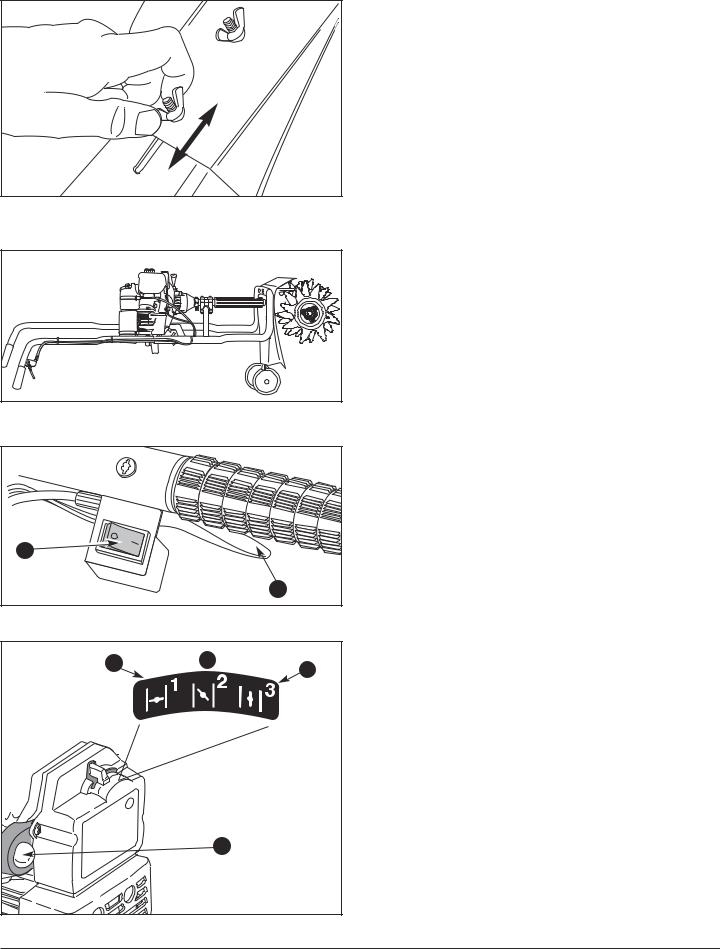
Description of Parts – Figs. 7-8
1. |
Throttle Trigger |
4. |
Full Choke Position (1) |
2. |
Ignition Switch |
5. |
Partial Choke Position (2) |
3. |
Primer |
6. |
Run Position (3) |
|
Description des pièces – Figs. 7-8 |
||||
|
1. |
Manette des gaz |
4. |
Étranglement maximum |
|
|
2. |
Contact d'allumage |
|
Position (1) |
|
|
5. |
Position d'étranglement |
|||
Fig. 5 |
3. |
Amorceur |
|||
|
partielle (2) |
||||
|
|
|
|
||
6. Position Marche (3)
Beschreibung der Teile – Abb. 7-8 |
|||
1. |
Gashebel |
4. |
volle Chokeposition (1) |
2. |
Zündschalter |
5. |
halbe Choke |
3. |
Einspritzvorrichtung |
|
Zwischenposition (2) |
|
|
6. |
Betriebsposition (3) |
Fig. 6
2 |
1 |
Fig. 7
4 |
6 |
|
|
|
3 |
Fig. 8
Descrizione dei componenti - figg. 7-8 |
|
|||
1. |
Leva acceleratore |
4. |
Posizione 1 |
(massimo) |
2. |
Accensione |
5. |
Posizione 2 |
(parziale) |
3. |
Innesco |
6. |
Posiz. 3 (normale) |
|
Descrição das peças – Figuras 7-8
1. |
Gatilho do acelerador |
4. |
Posição de |
2. |
Interruptor da ignição |
|
estrangulamento total (1) |
3. |
Iniciador |
5. |
Posição de estran- |
|
|
|
gulamento parcial (2) |
|
|
6. |
Posição de operação (3) |
Descripción de piezas – Fig. 7-8
1. |
Gatillo del regulador |
4. |
Posición de obturación |
|
2. |
Interruptor de |
|
completa (1) |
|
|
|
|||
|
encendido |
5. |
Posición de obturación |
|
3. |
Cebador |
|
parcial (2) |
|
6. |
Posición de marcha (3) |
|||
|
|
6

1 |
3 |
3 |
2 |
2 |
4 |
4 |
Fig. 11
3 |
3 |
4 |
Cultivator |
2 |
Fig. 12
Description of Parts – Fig. 9-12
1. |
Starter Rope |
4. |
Hubs |
|
2. |
“A” Tine |
5. |
Click Pin |
|
3. |
“B” Tine |
|
|
|
Description des pièces – Fig. 9-12 |
||||
1. |
Corde de |
3. |
Fraise « B » |
|
|
démarrage |
4. |
Moyeux |
|
2. |
Fraise « A » |
|||
5. |
Goupille à cliquet |
|||
|
|
|||
Beschreibung der Teile – Abb. 9-12 |
||||
1. |
Starterleine |
4. |
Radkappen |
|
2. |
Blatt „A“ |
5. |
Splint |
|
3. |
Blatt „B“ |
|
|
|
Descrizione dei componenti - figg. 9-12 |
||||
1. |
Avvio a strappo |
4. |
Mozzi |
|
2. |
Lama “A” |
5. |
Ganci dei |
|
3. |
Lama “B” |
|
|
|
Descrição das peças – Figuras 9-12 |
||||
1. |
Corda de |
3. |
Forquilha “B” |
|
|
arranque |
4. |
Eixos |
|
2. |
Forquilha “A” |
|||
5. |
Pino de clique |
|||
|
|
|||
Descripción de piezas – Fig. 9-12 |
||||
1. |
Cuerda de |
3. |
Diente “B” |
|
|
arranque |
4. |
Cubos |
|
2. |
Diente “A” |
|||
5. |
Espiga de chasquido |
|||
|
|
|||
7
1 
2 |
2 |
|
Fig. 13
3
Fig. 14
Fig. 15
Fig. 16
Fig. 17
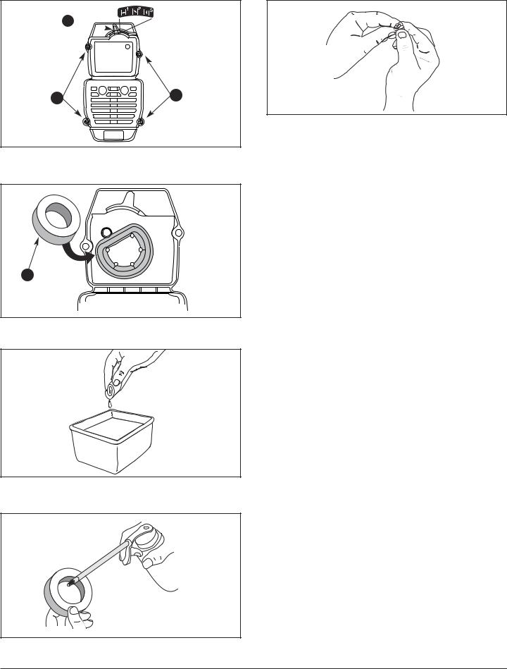
Description of Parts – Figs. 13-17
1. |
Choke Lever |
3. |
Air Filter |
2. |
Screw |
|
|
Description des pièces – Figs. 13-17 |
|||
1. |
Levier d'étrangleur |
3. |
Filtre à air |
2. |
Vis |
|
|
Beschreibung der Teile – Abb. 13-17 |
|||
1. |
Chokehebel |
3. |
Luftfilter |
2. |
Schraube |
|
|
Descrizione dei componenti – figg. 13-17
1. |
Leva starter |
3. |
Filtro dell’aria |
2. |
Vite |
|
|
Descrição das peças – Figuras 13-17 |
|||
1. |
Alavanca do |
2. |
Parafuso |
|
estrangulador |
3. |
Filtro de ar |
|
|
||
Descripción de piezas – Fig. 13-17 |
|||
1. |
Palanca del |
2. |
Tornillo |
|
obturador |
3. |
Filtro de aire |
|
|
||
8
1
Fig. 18
2 
0.5 mm.
(0.02 in.)
Fig. 19
Description of Parts – Figs. 18-19
|
1. |
Idle Speed Adjuster |
2. |
Spark Plug |
|
Description des pièces – Figs. 18-19 |
|||
|
1. |
Vis de réglage du |
2. |
Bougie |
|
|
ralenti |
|
|
|
Beschreibung der Teile – Abb. 18-19 |
|||
|
1. |
Lehrlaufdrehzahl- |
2. |
Zündkerze |
|
|
regler |
|
|
|
Descrizione dei componenti – figg. 18-19 |
|||
|
1. |
Vite regime minimo |
2. |
Candela |
|
Descrição das peças – Figuras 18-19 |
|||
|
||||
|
||||
|
||||
|
1. |
Regulador da |
2. |
Vela |
|
|
velocidade lenta |
|
|
|
Descripción de piezas – Fig. 18-19 |
|||
|
1. |
Ajuste de marcha |
2. |
Bujía de encendido |
|
|
lenta |
|
|
9

10
SAFETY WARNINGS
READ ALL INSTRUCTIONS
BEFORE OPERATING
•Read the operator’s manual carefully. Be thoroughly familiar with the controls and proper use of the unit. Know how to stop the unit and disengage the controls quickly.
•Never allow children to operate the unit. Never allow any one but adults to operate the unit without proper instruction.
•Inspect the unit before use. Replace damaged parts. Check for fuel leaks. Make sure all fasteners are in place and secure. Failure to do so can result in personal injury to the operator and bystanders, as well as damage to the unit
•Be aware of the risk of injury to the head, hands and feet.
•Carefully inspect the area before starting the unit. Remove all debris and hard or sharp objects such as rocks, broken glass, wire, or string which can be thrown or become entangled in the tines.
•Clear the area of children, bystanders, and pets. At a minimum, keep all children, bystanders and pets outside a 15 meters (50 ft.) radius; there still may be a risk to bystanders from thrown objects. Bystanders should wear eye protection. If you are approached, stop the unit immediately.
SAFETY WARNINGS
WARNING: Petrol (gasoline) is highly flammable, and its vapors can explode if ignited. Take the following precautions:
•Store fuel only in containers specifically designed and approved for the storage of such materials.
•Always stop the engine and allow it to cool before filling the fuel tank. Never remove the cap of the fuel tank, or add fuel, when the engine is hot.
•Add fuel in a clean, well-ventilated area outdoors where there are no sparks or flames. Slowly remove the fuel cap only after stopping engine. Do not smoke while fueling or mixing fuel. Wipe up any spilled fuel from the unit immediately.
•Move the unit at least 9.1 m (30 ft.) from the fueling source and site before starting the engine. Do not smoke, keep sparks and open flames from the area while adding fuel or operating the unit.
WHILE OPERATING
•Never start or run the unit inside a closed room or building. Breathing exhaust fumes can kill. Operate this unit only in a well ventilated area outdoors.
•Wear safety glasses or goggles and ear/hearing protection when operating this unit. Wear safety glasses for all operations, i.e. preparation, operation and maintenance.
•Wear heavy, long pants, boots, gloves and long sleeve shirt. Do not wear, short pants, sandals or go barefoot. Wear protective boots that will improve footing.
•The tine guard and wheel bracket assembly must always be in place while operating.
•Be sure the tines are not in contact with anything before starting the unit.
•The operator and unit must be in a stable position while starting. See Fig. 9 and Starting/Stopping Instructions.
•Use the right tool. Only use this tool for the purpose intended.
•This unit has a clutch. The tines remain stationary when the engine is idling. If they do not, have the unit adjusted by an authorized
service technician.
•Do not force unit. It will do the job better and with less likelihood of injury at a rate for which it was designed.
•Use extreme caution when reversing or pulling the unit towards you.
•Do not overreach, take extra care when working on slopes or inclines. Always keep proper footing and balance. To prevent overturning, operate the tiller up and down the slope or incline.
•Never operate the unit on slippery surfaces or steep slopes.
•Always hold the unit with both hands when operating. Keep a firm grip on the handlebar grips.
•Be careful when tilling hard ground. The tines may catch in the ground and propel the cultivator forward. If this occurs, let go of the handlebars and do not restrain the machine.
•The tines become very sharp from use. Always wear heavy gloves when handling, removing, installing or cleaning the tines.
•Do not touch the engine, muffler or gearbox. These parts get extremely hot from operation. When turned off they remain hot for a short time.
•Exercise extreme caution when operating on or crossing gravel drives, walks or roads. Stay alert for hidden hazards or traffic. Do not carry passengers.
•If you strike or become entangled with a foreign object, stop the engine immediately and check for damage. Do not operate before repairing damage. Do not operate the unit with loose or damaged parts.
11

SAFETY WARNINGS
•If the unit should start to vibrate abnormally, stop the engine and check imediately for the cause. Vibration is generally a warning of trouble.
•Always stop the engine when operation is delayed or when walking from one location to another.
•Stop and switch the engine to off for maintenance, repair, or for changing the tines or other attachments.
•Use only accessories and replacement parts approved by the manufacturer when servicing this unit. These parts are available from your authorized service dealer.
•Do not use parts, accessories or attachments not authorized for this unit. Doing so could lead to serious injury to the user, or damage to the unit, and void your warranty.
•Keep unit clean of vegetation and other materials. They may become lodged between the tines and gearbox or guard.
•Keep hands, face, and feet at a distance from all moving parts. Do not touch or try to stop the tines when they are rotating.
OTHER SAFETY WARNINGS
•Never store the unit, with fuel in the tank, inside a building where fumes may reach an open flame or spark.
•Allow the engine to cool before storing or transporting. Be sure to secure the unit while transporting.
•Clean after each use, see Cleaning and Storage instructions.
•Clean the tines with a hose and water. Wipe the tines with a light machine oil to prevent rust.
•Keep these instructions. Refer to them often and use them to instruct other users. If you loan someone this unit, also loan them these instructions.
SAVE THESE INSTRUCTIONS
12

SAFETY AND INTERNATIONAL SYMBOLS
This operator's manual describes safety and international symbols and pictographs that may appear on this product. Read the operator's manual for complete safety, assembly, operating and maintenance and repair information.
SYMBOL |
MEANING |
SYMBOL |
MEANING |
||
|
• SAFETY ALERT SYMBOL |
|
|
|
• IGNITION SWITCH |
|
|
|
|
||
|
Indicates danger, warning, or caution. |
|
|
|
ON / START / RUN |
|
May be used in conjunction with |
|
|
|
|
|
|
|
|
|
|
|
other symbols or pictographs. |
|
|
|
|
•WARNING - READ OPERATOR'S MANUAL
Read the Operator’s Manual(s) and follow all warnings and safety instructions. Failure to do so can result in serious injury to the operator and/or bystanders.
•WEAR EYE AND HEARING PROTECTION
WARNING: Thrown objects and loud noise can cause severe eye injury and hearing loss. Wear eye protection meeting ANSI Z87.1-1989 standards and ear protection when operating this unit. Use a full face shield when needed.
•THROTTLE CONTROL
Indicates “HIGH” or “FASTEST” speed.
•THROTTLE CONTROL
Indicates “IDLE,” “LOW” or “SLOWEST” speed.
•WEAR HEAD PROTECTION
WARNING: Falling objects can cause severe head injury. Wear head protection when operatin this unit.
•UNLEADED PETROL
Always use clean, fresh unleaded petrol.
•OIL
Refer to operator's manual for the proper type of oil.
•IGNITION SWITCH
OFF or STOP
•HOT SURFACE WARNING
Do not touch a hot muffler or cylinder. You may get burned. These parts get extremely hot from operation. When turned off they remain hot for a short time.
•SHARP BLADE
WARNING: Stop the engine and allow the tines to stop before installing or removing tines, or before cleaning or performing any maintenance. Keep hands and feet away from rotating tines.
•KEEP BYSTANDERS AWAY
WARNING: Objects can be thrown from unit. Do not operate unit without proper attachments and guards in place.
•THROWN OBJECTS CAN CAUSE SEVERE INJURY
WARNING: Keep all bystanders, especially children and pets, at least 15 meters (50 ft.) from the operating area.
• CHOKE CONTROL
1 • FULL choke position.
2 • PARTIAL choke position.
3 • RUN position.
• PRIMER BULB
Push primer bulb, fully and slowly, 10 times.
13

ASSEMBLY INSTRUCTIONS
NOTE: This unit is shipped without gasoline or oil. In order to avoid damage to the unit, refer to Oil and Fuel Information to put oil and gas in the crankcase before attempting to start it.
NOTE: Before setting up your cultivator, disconnect the spark plug wire from the spark plug.
Positioning the Handlebars
1.Loosen the two knobs on the inside of the handlebars (Fig. 1).
2.With the unit upright, swing the handlebars up into the operating position (Fig. 1).
NOTE: Take care not to pinch the throttle cable or switch wires when positioning the handlebar.
3. Tighten the knobs to secure the handlebars in place.
NOTE: Do not over-tighten the knobs.
Adjusting Tine Depth
Tine adjustment will vary depending on the type of soil being cultivated and how it will be used. Generally, adjusting the tines to break the soil 4 to 6 inches is recommended for most gardens.
Adjust the tines as follows:
1.Stop the engine and disconnect the spark plug wire.
2.Loosen (do not remove) the two wing nuts (5) on the tine guard (4) (Fig. 3).
3.Slide the wheel down for shallower and up for deeper tine penetration.
4.Once the tines are in the desired position, tighten the wing nuts, making sure that the carriage bolts are seated properly through the bracket (Fig. 4).
5.If the tine depth is not correct, repeat steps 2 to 4.
6.Reconnect the spark plug wire and continue use.
OIL AND FUEL RECOMMENDATIONS
RECOMMENDED OIL TYPE
Use high quality oil formulated for use in 2-cycle, aircooled engines. Mix the oil according to the instructions on the 2-cycle engine oil container, 40:1 (2.5 %).
RECOMMENDED FUEL TYPE
Always use clean, fresh, unleaded petrol (gasoline).
OIL AND FUEL MIXING INSTRUCTIONS
Old and/or improperly mixed fuel are the main reasons for the unit not running properly. Be sure to use fresh, clean unleaded fuel. Follow the instructions carefully for the proper fuel/oil mixture.
Thoroughly mix the proper ratio of 2-cycle engine oil with unleaded petrol, 40:1 (2.5 %). Do not mix them directly in the tank.
14

OPERATING INSTRUCTIONS
STARTING INSTRUCTIONS
1.Mix petrol (gasoline) with oil. Fill fuel tank with petrol/oil mixture. See Oil and Fuel Mixing Instructions.
2.Put the ignition switch in the START (I) position (Fig. 7).
3.Fully press and release primer bulb (3) slowly 10 times. Fuel should be felt and visible in the bulb (Fig. 8). If fuel hasn’t entered the bulb, press three more times, or until it does.
4.Place the choke lever in Position 1 (Fig. 8).
NOTE: Tilt the unit back slightly to bring the tines off the ground when starting.
5.Pull the starter rope (7) out with a controlled and steady motion 3 times (Fig. 9).
NOTE: The unit uses Advanced Starting Technology™, which significantly reduces the effort required to start the engine. You must pull the starter rope out far enough to hear the engine attempt to start. There is no need to pull the rope briskly-- there is no harsh resistance when pulling. Be aware that this starting method is vastly different from (and much easier than) what you may be used to.
6.Place the choke lever in Position 2 (Fig. 8).
7.While squeezing the throttle control (1) (Fig. 7), pull the starter rope with a controlled and steady motion to start the engine (Fig. 9).
8.Keep the throttle squeezed and allow the engine to warm up for 15 to 30 seconds.
9.Place the choke lever in Position 3. Release the throttle control to the idle position and begin operation.
NOTE: If the engine does not start, go back to step 3.
NOTE: If the engine fails to start after a few attempts, place the blue choke lever in Position 3 and squeeze the throttle control. Pull the starter rope 3 to 8 times. The engine should start. If not, repeat.
NOTE: If the engine is already warm, make sure the On/Off Stop control is in the ON position and start the unit with the blue choke lever in Position 2. After the unit starts, move the blue choke lever to Position 3.
STOPPING INSTRUCTIONS
1.Release your hand from the throttle control (Fig. 7). Allow the engine to cool down by idling.
2.Put the ignition switch in the STOP (O) position.
OPERATING TIPS
WARNING: Dress properly to reduce the risk of injury when operating this unit. Do not wear loose clothing or jewelry. Wear eye and ear/hearing protection. Wear heavy, long pants, boots and gloves. Do not wear short pants, sandals or go barefoot.
1.Move the cultivator to the work area prior to starting the engine. The cultivator may be transported by pushing it on wheels or carrying it by the shaft tube grip.
WARNING: To prevent serious personal injury, never pick-up or carry the unit whilst the engine is running.
2.Start the unit per Starting Instructions.
3.With the engine running and the tines off the ground, depress the throttle control to increase the engine speed.
4.Holding both of the handlebar grips firmly, slowly lower the cultivator until the tines make contact with the ground (Fig. 10).
5.As cultivating action begins, pull back on the cultivator so that the tines can penetrate the ground.
6.Once the ground has been broken, continue at a moderate pace until you are familiar with the controls and the handling of the cultivator.
7.If the tines are digging too deep or not deep enough, adjust the tines as explained in Adjusting Tine Depth.
TRANSPORTING THE UNIT
WARNING: To prevent serious personal injury, always stop the engine when operation is delayed or when transporting the unit from one location to another.
1.Stop the engine.
2.Slide the wheel bracket assembly all the way down.
3.Tilt the unit back until the tines clear the ground.
4.Push or pull the unit to the next location to be cultivated.
NOTE: The cultivator can also be carried by the shaft tube grip
15

MAINTENANCE AND REPAIR INSTRUCTIONS
Tine Removal and Replacement
All 4 tines should be replaced at the same time because they will wear evenly through normal use. Work on one side at a time.
WARNING: To prevent serious personal injury, always wear heavy gloves when handling the tines.
1.Put the On/Off Stop Control in the STOP (O) position and disconnect the spark plug wire.
NOTE: It may be necessary to lay the cultivator back in a horizontal position on a flat level surface with the upper handle touching the ground.
2.Remove the click pin (4) from each end of the tine shaft. Slide the tines off of the shaft (Fig. 11).
3.Clean and oil the shaft.
4.When you are reinstalling tines, lay out the tines and compare them to those shown in Figure 12. Note specifics about each tine: its hub, curvature and lettering (“A” or “B”). This will help make sure that you are placing the correct tines in the correct order.
NOTE: If you look closely, you can see a slight curvature in the tine tips. These curves should point toward the front of the cultivator when the tines are installed. Figure 12 shows the curve in each tine.
5.Using Figures 11 and 12 for reference, slide on the new tines with the hubs facing outward.
The tines are stamped “A” or “B.” The tine order should be “B, A, B, A” from left to right when facing the cultivator from the front.
6.Secure the new tines to the shaft with click pins (4). It may be necessary to wash the dirt off the tines and shaft for ease of removal.
AIR FILTER MAINTENANCE
Removing the Air Filter/Muffler Cover
1. Place the choke lever (1) in the position 2 (Fig. 13).
NOTE: The choke lever must be in position 2 to remove the air filter/muffler cover.
2.Remove the four screws (2) securing the air filter/muffler cover (Fig. 13). Use a flat blade or T-20 Torx bit screwdriver.
3.Pull the cover from the engine. Do not force.
Cleaning the Air Filter
Clean and re-oil the air filter every 10 hours of operation. It is an important item to maintain. Failure to maintain your air filter properly can result in poor performance or can cause permanent damage to your engine.
1.Remove the air filter/muffler cover. See Removing the Air filter/Muffler Cover.
2.Remove the air filter (3) from inside the air filter/muffler cover (Fig. 14).
3.Wash the filter in detergent and water (Fig. 15). Rinse the filter thoroughly. Squeeze out excess water. Allow it to dry completely.
4.Apply enough clean oil to lightly coat the filter (Fig. 16).
5.Squeeze the filter to spread and remove excess oil.
6.Replace the air filter inside the air filter/muffler cover (Fig. 14).
NOTE: Operating the unit without the air filter and air filter/muffler cover assembly, will VOID the warranty.
Reinstalling the Air Filter/Muffler Cover
1.Place the air filter/muffler cover over the back of the carburetor and muffler.
NOTE: The choke lever must be in position 2 to install the air filter/muffler cover.
2.Insert the four (4) screws into the holes in the air filter/muffler cover (Fig. 13) and tighten. Use a T-20 Torx bit screwdriver. Do not over tighten. Do not force.
16

MAINTENANCE AND REPAIR INSTRUCTIONS
Check Fuel Mixture
Old and/or improperly mixed fuel is usually the reason for the unit not running properly. Drain and refill the tank with fresh, properly mixed fuel prior to making any adjustments.
Clean Air Filter
The condition of the air filter is important to the operation of the unit. A dirty air filter will restrict air flow and change the air/fuel mixture. This is often mistaken for an out of adjustment carburetor. Check the condition of the air filter before adjusting the idle speed screw. Refer to Air Filter Maintenance.
Adjust Idle Speed Adjuster
If after checking the fuel mixture and cleaning the air filter the engine
still will not idle, adjust the idle speed adjuster as follows.
1.Start the engine and let it run about 2–3 minutes at a high speed (full throttle) to warm up.
NOTE: Ensure the tines are not in contact with the ground when adjusting the idle.
2.Release the throttle trigger and let the engine idle. If the engine stops, insert a small phillips into the hole in the air filter/muffler cover (Fig. 18). Turn the idle speed adjuster in, clockwise, 1/8 of a turn at a time (as needed) until the engine idles smoothly.
NOTE: The tines should not rotate when the engine idles.
3.If the tines rotate when the engine idles, turn the idle speed adjuster counterclockwise 1/8 of a turn at a time (as needed), to reduce idle speed.
Checking the fuel mixture, cleaning the air filter, and adjusting the idle
speed screw should solve most engine problems.
If not and:
•The engine will not idle,
•The engine hesitates or stalls on acceleration,
•There is a loss of engine power,
Have the carburetor adjusted by an authorized service dealer.
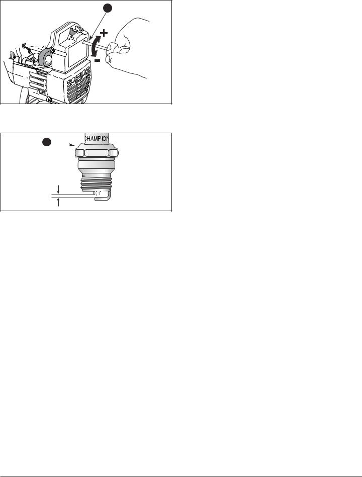
REPLACING THE SPARK PLUG
Use a Champion RDJ7Y spark plug (or equivalent). The correct air gap is 0.5 mm (0.020 in.). Remove the plug after every 50 hours of operation and check its condition.
1.Stop the engine and allow it to cool. Grasp the plug wire firmly and pull the cap from the spark plug.
2.Clean dirt from around the spark plug.
3.Replace cracked, fouled or dirty spark plug. Set the air gap at 0.5 mm (0.020 in.) using a feeler gauge (Fig. 19).
4.Install a correctly gapped spark plug in the cylinder head. Tighten by turning the 5/8 in. socket clockwise until snug.
Do not over tighten.
CLEANING
Use a small brush to clean off the outside of the unit. Do not use strong detergents. Household cleaners that contain aromatic oils
such as pine and lemon, and solvents such as kerosene, can damage plastic housing or handle. Wipe off any moisture with a soft cloth.
17

MAINTENANCE AND REPAIR INSTRUCTIONS
STORAGE
•Never store the unit with fuel in the tank where fumes may reach an open flame or spark.
•Allow the engine to cool before storing.
•Store the unit in a dry place, locked up or up-high to prevent unauthorized use or damage. Keep out of the reach of children.
LONG TERM STORAGE
If the unit will be stored for an extended time, use the following storage procedure.
1.Drain all fuel from the fuel tank and drain into a container with the same 2-cycle fuel mixture. Do not use fuel that has been stored for more than 60 days.
2.Start the engine and allow it to run until it stalls. This ensures that all fuel has been drained from the carburetor.
3.Allow the engine to cool. Remove the spark plug and put 30 ml (1 oz.) of any high quality motor oil or 2- cycle oil into the cylinder. Pull the starter rope slowly to distribute the oil. Reinstall the spark plug.
NOTE: Remove the spark plug and drain all of the oil from the cylinder before attempting to start the unit after storage.
4.Thoroughly clean the unit and inspect for any loose or damaged parts. Repair or replace damaged parts and tighten loose screws, nuts or bolts. The unit is ready for storage.
5Store the unit in a dry place, locked up or up-high to prevent unauthorized use or damage. Keep out of the reach of children.
18

TROUBLESHOOTING |
|
|
|
ENGINE WILL NOT START |
|
C A U S E |
A C T I O N |
Empty fuel tank |
Fill fuel tank with fresh fuel |
Primer bulb wasn't pressed enough |
Press primer bulb fully and slowly 10 times |
Engine is flooded |
Squeeze the trigger and pull the starter rope |
Old fuel |
Drain fuel tank and add fresh fuel |
Fouled spark plug |
Replace or clean the spark plug |
|
|
ENGINE WILL NOT IDLE / LOW IDLE SPEED |
|
C A U S E |
A C T I O N |
Air filter is plugged |
Replace or clean the air filter |
Old fuel |
Drain fuel tank and add fresh fuel |
Improper carburetor adjustment |
Adjust according to the Carburetor Adjustments section |
|
|
ENGINE WILL NOT ACCELERATE |
|
C A U S E |
A C T I O N |
Old fuel |
Drain fuel tank and add fresh fuel |
Improper carburetor adjustment |
Take to an authorized service dealer for an adjustment |
Tines bound with material |
Stop the engine and clean the tines |
Dirty air filter |
Clean or replace the air filter |
|
|
ENGINE LACKS POWER OR STALLS WHEN CUTTING |
|
C A U S E |
A C T I O N |
Old fuel |
Drain fuel tank and add fresh fuel |
Improper carburetor adjustment |
Take to an authorized service dealer for an adjustment |
Fouled spark plug |
Replace or clean the spark plug |
|
|
If further assistance is required, contact your local authorized service dealer.
All information, illustrations, and specifications in this manual are based on the latest product information available at the time of printing. We reserve the right to make any changes at any time without notice.
19

|
SPECIFICATIONS |
|
|
ENGINE |
|
Engine Type........................................................................................................................................... |
Air-Cooled, 2-Cycle |
Displacement .............................................................................................................................................................. |
31 cc |
Idle Speed RPM ......................................................................................................................................... |
2,600-3,600 rpm |
Operating RPM................................................................................................................................................... |
7,800+ rpm |
Clutch Type ......................................................................................................................................................... |
Centrifugal |
Ignition Type.......................................................................................................................................................... |
Electronic |
On/Off Stop Control....................................................................................................................................... |
Rocker Switch |
Spark Plug Type .................................................................................................................................... |
Champion RDJ-7Y |
Spark Plug Gap .................................................................................................................................. |
0.50 mm (0.020 inch) |
Lubrication................................................................................................................................................... |
Fuel/Oil Mixture |
Fuel/Oil Ratio.................................................................................................................................................................. |
40:1 |
Carburetor....................................................................................................................................... |
Diaphragm, All-Position |
Starter............................................................................................................................................................................. |
AST |
Muffler ..................................................................................................................................................... |
Baffled with Guard |
Throttle............................................................................................................................................................ |
Spring Return |
Fuel Tank Capacity................................................................................................................................. |
415 ml (14 ounces) |
DRIVE SHAFT & CULTIVATOR
Drive Shaft Tube . . . . . . . . . . . . . . . . . . . . . . . . . . . . . . . . . . . . . . . . . . . . . . . . . . . . . . . . . . . . . . . . . . . . . . . . . . Steel Tube Throttle Control . . . . . . . . . . . . . . . . . . . . . . . . . . . . . . . . . . . . . . . . . . . . . . . . . . . . . . . . . . . . . . . . . . . . . Finger-Tip Trigger Cultivating Path Width (Maximum) . . . . . . . . . . . . . . . . . . . . . . . . . . . . . . . . . . . . . . . . . . . . . . . . . . . . . . . . 22.86 cm (9 in.) Cultivating Depth (Maximum) . . . . . . . . . . . . . . . . . . . . . . . . . . . . . . . . . . . . . . . . . . . . . . . . . . . . . . . . . . . . . 12.7 cm (5 in.) Vibration Level (Idle)* . . . . . . . . . . . . . . . . . . . . . . . . . . . . . . . . . . . . . . . . . . . . . . . . . . . . . . . . . . . . . . . . . . . . . . . . 16 m/s2 Sound Power Level (No Load Idle RPM) † . . . . . . . . . . . . . . . . . . . . . . . . . . . . . . . . . . . . . . . . . . . . . . . . . . 96.0 LweqdB(A) Sound Power Level (No Load Operating RPM) † . . . . . . . . . . . . . . . . . . . . . . . . . . . . . . . . . . . . . . . . . . . 118.0 LweqdB(A) Approximate Mass (without fuel) . . . . . . . . . . . . . . . . . . . . . . . . . . . . . . . . . . . . . . . . . . . . . . . . . . . . . . . . . . . . 12 kg (26 lbs)
20
AVERTISSEMENTS DE SÉCURITÉ
LISEZ TOUTES LES INSTRUCTIONS
AVANT L’UTILISATION
•Veuillez lire le manuel de l'utilisateur attentivement. Familiarisez-vous avec les commandes et l'utilisation correcte de l’appareil. Sachez comment arrêter l’appareil et désactiver les commandes rapidement.
•Ne laissez pas les enfants faire fonctionner l’ appareil. Ne laissez jamais des adultes actionner l’appareil sans formation préalable.
•Contrôlez l’appareil avant de l’utiliser. Remplacez les pièces endommagées. Vérifiez qu’il n’y a pas de fuite de carburant. Assurez-vous que la boulonnerie est bien en place et que tous les éléments sont correctement fixés. Le non-respect de ces règles peut entraîner des blessures corporelles pour l’utilisateur ou les personnes se trouvant à proximité, ainsi qu’une détérioration de l’appareil.
•Attention aux risques de blessure à la tête, aux mains et aux pieds.
•Inspectez soigneusement la zone avant de démarrer l’appareil. Enlevez tous les débris et objets durs ou tranchants pouvant être projetés ou happés par les dents : cailloux, verre brisé, fil ou ficelle.
•Éloignez enfants, spectateurs et animaux de la zone. Tenez-les à au moins 15 m (50 pi) de là, mais sachez que les spectateurs risquent quand même d'être atteints par des objets projetés. Les spectateurs doivent porter des protections oculaires. Arrêtez immédiatement l’appareil si quelqu'un s'approche de vous.
CONSIGNES DE SECURITE
ATTENTION : L’essence est hautement inflammable et les vapeurs d’essence peuvent exploser en cas de contact avec une flamme. Prenez les précautions suivantes :
•Stockez toujours le carburant dans des conteneurs spécialement conçus et agréés pour le stockage de ce type de produit.
•Arrêtez toujours le moteur et laissez-le refroidir avant de remplir le réservoir. Vous ne devez jamais enlever le bouchon du réservoir ou ajouter du carburant tant que le moteur est chaud.
•Ajoutez le carburant dans un lieu extérieur, aéré et propre, à l'abri d’étincelles ou de flammes. Ne remplissez jamais le réservoir de carburant à l'intérieur. Retirez lentement le bouchon du réservoir, seulement après avoir arrêté le moteur. Ne fumez pas pendant le remplissage ou le mélange de carburant. Essuyez immédiatement tout déversement de carburant.
•Éloignez l'appareil d'au moins 9,1 m (30 pi) des source et site de ravitaillement avant de démarrer le moteur. Ne fumez pas et éloignez toute source d'étincelles ou de flammes vives du lieu de ravitaillement ou d’utilisation de l'appareil.
PENDANT L’UTILISATION
•Ne démarrez et n’utilisez jamais l’appareil dans une pièce ou un bâtiment fermé. L’inhalation des fumées d’échappement peut être mortelle. N’utilisez cet appareil qu’en extérieur, dans une zone bien ventilée.
•Portez des lunettes de sécurité et des protège-oreilles lorsque vous faites marcher l'appareil. Portez des lunettes de sécurité pour toutes les activités, ex. préparation, fonctionnement, entretien.
•Portez des pantalons épais et longs, des bottes, des gants et une chemise à manches longues. Ne marchez pas pieds nus et évitez les pantalons courts et les sandales. Portez des bottes de protection capables de vous assurer une meilleure stabilité.
•Le protecteur de dents et le support de roue doivent toujours être mis pour utiliser l'appareil.
•Avant de démarrer l'appareil, assurez-vous que les dents ne touchent aucun objet.
•L’utilisateur et l’appareil doivent être en position stable lors du démarrage. Reportez-vous à la Figure 9 et aux Instructions pour le démarrage/l’arrêt.
•Utilisez l’outil approprié. N’utilisez cet outil que pour l’usage auquel il est destiné.
•Cet appareil est muni d'un embrayage. Les dents restent immobiles lorsque le moteur est au ralenti. Si ce n'est pas le cas, faites régler l'appareil par un technicien agréé.
•Ne forcez pas l’appareil. Il posera moins de risques de blessures et fonctionnera mieux à la vitesse pour laquelle il a été conçu.
•Soyez très prudent lorsque vous faites marche arrière ou que vous tirez l’appareil vers vous.
•Ne travaillez pas à bout de bras et faites très attention lorsque vous travaillez sur des pentes ou inclinaisons. Gardez toujours un bon équilibre. Pour éviter que l’appareil ne se renverse, dirigez le cultivateur le long de la pente.
•Ne faites jamais fonctionner l’appareil sur des surfaces glissantes ou des pentes abruptes.
•Ne vous étirez pas et faites très attention lorsque vous travaillez sur des pentes ou inclinaisons abruptes. Tenez-vous toujours en équilibre.
•Faites attention lorsque vous labourez en sol dur. Les dents pourraient accrocher le sol et projeter le cultivateur vers l’avant. Si cela se produit, lâchez le guidon sans tenter de retenir l’appareil.
•Tenez toujours l'appareil des deux mains lorsqu’il est en marche. Agrippez fermement les deux poignées du guidon.
•Les dents deviennent très tranchantes à l’usage. Portez toujours des gants lorsque vous manipulez, retirez, installez ou nettoyez les dents.
21

AVERTISSEMENTS DE SÉCURITÉ
•Faites extrêmement attention lorsque vous traversez ou opérez sur des allées, chemins ou routes en gravier. Restez vigilant quant à la présence de dangers ou de véhicules cachés. Ne transportez pas de passagers.
•Ne touchez pas le moteur, l’échappement ou la boîte d'engrenages. Ces pièces deviennent très chaudes à l'utilisation. Elles restent chaudes brièvement après l'arrêt.
•Si l’appareil se met à vibrer de manière anormale, arrêtez le moteur et procédez immédiatement à une vérification. Les vibrations indiquent généralement la présence d’un problème.
•En cas de contact avec un corps étranger, arrêtez le moteur
immédiatement et vérifiez que l’appareil n’est pas endommagé. N’utilisez pas l’appareil avant de l’avoir remis en état. N’utilisez pas l’appareil si certaines pièces sont mal serrées ou endommagées.
•Arrêtez toujours le moteur si le travail est retardé ou si vous vous déplacez d’un lieu à l’autre.
•Arrêtez et éteignez le moteur dans ces cas-ci : entretien, réparation, changement de dents ou autres accessoires.
•Utilisez uniquement des accessoires et des pièces de rechange homologués par le fabricant pour l'entretien. Elles sont disponibles auprès de votre concessionnaire agréé.
•N'utilisez pas de pièces ou accessoires non autorisés pour cet appareil. Cela pourrait causer des blessures graves ou endommager l'appareil et annuler la garantie.
•Nettoyez toute accumulation de végétation ou autres matières pouvant se loger entre les dents, la boîte d'engrenages ou le protecteur.
•Gardez les mains, le visage et les pieds éloignés des pièces mobiles. Ne touchez pas les dents et n'essayez pas de les arrêter lorsqu'elles tournent.
AUTRES CONSIGNES DE SECURITE
•S’il y a du carburant dans le réservoir, n’entreposez jamais
l’appareil dans un bâtiment où les vapeurs pourraient entrer en contact avec une flamme nue ou une étincelle.
•Laissez le moteur refroidir avant de ranger ou de transporter
l’appareil. Veillez à protéger l’appareil pour le transport.
•Nettoyez l’appareil après chaque utilisation ; reportezvous aux instructions de la section “ Nettoyage et entreposage ”.
•Nettoyez les dents en arrosant de l’eau avec un tuyau. Essuyez ensuite les dents avec une huile mécanique légère pour éviter la rouille.
•Conservez ce manuel. Reportez-vous souvent aux instructions qu’il comporte et transmettez ces instructions aux autres utilisateurs. Si vous prêtez cet appareil, prêtez également ces instructions.
CONSERVEZ CES INSTRUCTIONS
22
 Loading...