

MSI Hetis 945, Hetis 945 Lite, MS-6410 User Manual

Hetis 945
Hetis 945 Lite
(MS-6410)
User’s Guide
G52-64101X2
FCC-B Radio Frequency Interference Statement
This equipment has been tested and
found to comply with the limits for a
class B digital device, pursuant to
part 15 of the FCC rules. These limits
are designed to provide reasonable
protection against harmful interference in a residential installation. This equipment
generates, uses and can radiate radio frequency energy and, if not installed and
used in accordance with the instruction manual, may cause harmful interference to
radio communications. However, there is no guarantee that interference will not
occur in a particular installation. If this equipment does cause harmful interference to
radio or television reception, which can be determined by turning the equipment off
and on, the user is encouraged to try to correct the interference by one or more of the
measures listed below.
=Reorient or relocate the receiving antenna.
=Increase the separation between the equipment and receiver.
=Connec the equipment into an outlet on a circuit different from that to which the
receiver is connected.
=Consult the dealer or an experienced radio/television technician for help.
Notice 1
The changes or modifications not expressly approved by the party responsible for
compliance could void the user’s authority to operate the equipment.
Notice 2
Shielded interface cables and A.C. power cord, if any, must be used in order to
comply with the emission limits.
VOIR LA NOTICE D’INSTALLATION AVANT DE RACCORDER AU RESEAU.
Micro-Star International
Hetis 945
This device complies with Part 15 of the FCC Rules. Operation is subject to the
following two conditions:
(1) this device may not cause harmful interference, and
(2) this device must accept any interference received, including interfer ence that may
cause undesired operation.
ii

Trademarks
All trademarks are the properties of their respective owners.
Intel® and Pentium® are registered trademarks of Intel Corporation.
PS/2 and OS®/2 are registered trademarks of International Business Machines
Corporation.
Windows® 95/98/2000/NT/XP are registered trademarks of Microsoft Corporation.
Netware® is a registered trademark of Novell, Inc.
Award® is a registered trademark of Phoenix Technologies Ltd.
AMI® is a registered trademark of American Megatrends Inc.
Revision History
Revision Revision History Date
v2.0 First release November 2006
Copyright Notice
The material in this document is the intellectual property of MICRO-STAR
INTERNATIONAL. We take every care in the preparation of this document, but no
guarantee is given as to the correctness of its contents. Our products are under
continual improvement and we reserve the right to make changes without notice.
iii

Safety Instructions
1. Always read the safety instructions carefully.
2. Keep this User’s Manual for future reference.
3. Keep this equipment away from humidity.
4. Lay this equipment on a reliable flat surface before setting it up.
5. The openings on the enclosure are for air convection hence protects the
equipment from overheating. DO NOT COVER THE OPENINGS.
6. Make sure the voltage of the power source and adjust properly 115/230V
before connecting the equipment to the power inlet.
7. Place the power cord such a way that people can not step on it. Do not
place anything over the power cord.
8. Always Unplug the Power Cord before inserting any add-on card or module.
9. All cautions and warnings on the equipment should be noted.
10. Never pour any liquid into the opening that could damage or cause electrical
shock.
11. If any of the following situations arises, get the equipment checked by a
service personnel:
- The power cord or plug is damaged.
- Liquid has penetrated into the equipment.
- The equipment has been exposed to moisture.
- The equipment has not work well or you can not get it work according to
User’s Manual.
- The equipment has dropped and damaged.
- The equipment has obvious sign of breakage.
12. DO NOT LEAVE THIS EQUIPMENT IN AN ENVIRONMENT UNCONDITIONED,
STORAGE TEMPERATURE ABOVE 400 C (1020F), IT MAY DAMAGE THE
EQUIPMENT.
CAUTION: Danger of explosion if battery is incorrectly replaced.
Replace only with the same or equivalent type recommended by the
manufacturer.
iv
Warning:
1. For every changes in powercordˇ¦s usage, please use an approved power
cord with condition greater or equal to H05VV-F,3G , 0.75mm2.
2. Internal part is hazardous moving parts, please keep fingers and other
body parts away.
3. For pluggable equipment, the socket-outlet shall be installed near the
equipment and shall be easily accessible.
4. Do not disable the protective earth pin from the plug, the equipment must
be connected to an earthed mains socket-outlet.
v
WEEE Statement
vi
vii
viii

CONTENTS
Chapter 1. Getting Started....................................................................................1-1
1.1 System Specifications...........................................................................1-2
1.2 System Configuration.............................................................................1-4
1.3 Thermal Solution...................................................................................1-10
Chapter 2. Introducing Mainboard......................................................................2-1
2.1 Mainboard Layout..................................................................................2-2
2.2 CPU.........................................................................................................2-4
Introduction to LGA 775 CPU................................................................2-4
CPU & Cooler Installation......................................................................2-5
2.3 Memory...................................................................................................2-8
Introduction to DDR2 SDRAM...............................................................2-8
DIMM Module Combination...................................................................2-9
Installing DDR2 Modules......................................................................2-9
2.4 Power Supply.......................................................................................2-10
ATX 20-Pin Power Connector: ATX1..................................................2-10
ATX 12V Power Connector: JPW1....................................................2-10
2.5 Front Panel.............................................................................................2-11
Audio Ports..........................................................................................2-11
USB Ports..........................................................................................2-11
IEEE 1394 Port (Standard only)..........................................................2-11
2.6 Rear Panel............................................................................................2-12
Mouse/Keyboard Connectors...........................................................2-12
Audio Port Connectors......................................................................2-13
VGA Port..........................................................................................2-13
Digital Panel Connector (DVI)(Standard only)....................................2-14
LAN (RJ-45) Jack...............................................................................2-15
USB Ports..........................................................................................2-15
Serial Ports.......................................................................................2-16
IEEE 1394 Port (Standard only).........................................................2-16
S-Video Out Connector (Standard only)............................................2-17
RCA Connector: TV1 (Standard only)................................................2-17
2.7 Connectors.............................................................................................2-18
IDE Connector: IDE1...........................................................................2-18
Card Reader Connector: CR1............................................................2-18
Serial ATA Connectors: SATA1/SATA2.............................................2-19
Fan Power Connectors: CPU_F1/SYS_F1.........................................2-19
Front Panel Connectors: JFP1...........................................................2-20
CD-in Connector: JCD1........................................................................2-20
ix

On-Board RCA out Connector: J2 (Standard only)...........................2-21
Internal Speaker Connector: CON1....................................................2-21
2.8 Jumper.................................................................................................2-22
Clear CMOS Jumper: JBAT1...............................................................2-22
2.9 Slot.......................................................................................................2-23
PCI Express Slot: PCIE_1 (For Riser Card Use Only).........................2-23
Chapter 3. System Assembly...............................................................................3-1
3.1 Overview...............................................................................................3-2
Installation Tools...................................................................................3-2
Screws.................................................................................................3-2
Checking the Items..............................................................................3-3
3.2 Installation Procedures............................................................................3-4
1. Removing Cover...............................................................................3-4
2. Installing HDD....................................................................................3-5
3. Installing Optical Drive.......................................................................3-6
4. Installing Card Reader (Optional).....................................................3-7
5. Installing Memory Modules................................................................3-8
6. Installing CPU....................................................................................3-9
7. Installing CPU Cooler......................................................................3-10
8. Restoring Chassis Cover...............................................................3-11
9. Installing Footstand.........................................................................3-12
Chapter 4. BIOS Setup...........................................................................................4-1
Entering Setup..............................................................................................4-2
Selecting the First Boot Device...........................................................4-2
Control Keys........................................................................................4-3
Getting Help.........................................................................................4-3
Main Menu............................................................................................4-3
Default Settings...................................................................................4-3
The Main Menu.............................................................................................4-4
Standard CMOS Features............................................................................4-6
Advanced BIOS Features............................................................................4-9
Advanced Chipset Features......................................................................4-12
Integrated Peripherals.................................................................................4-14
Power Management Setup..........................................................................4-17
System Informaion........................................................................................4-19
H/W Monitor................................................................................................4-20
Frequency / Voltage Control........................................................................4-21
Load Fail-Safe/Optimized Defaults..............................................................4-22
Set Supervisor/User Password...................................................................4-23
x

Chapter 5. Introduction to Realtek ALC888......................................................5-1
Installing the Realtek HD Audio Driver..........................................................5-2
Installation for Windows 2000/XP................................................................5-2
Software Configuration................................................................................5-4
Sound Effect................................................................................................5-5
Audio IO........................................................................................................5-6
Mixer.............................................................................................................5-9
Microphone.................................................................................................5-12
3D Audio Demo...........................................................................................5-13
Information..................................................................................................5-14
Using 2-, 4-, 6- & 8- Channel Audio Function.............................................5-15
xi

1
Getting Started
1.1 All-in-one Feature Set
1.2 System Specifications
1.3 System Configuration
1.1 System Specifications
Mainboard Model
† MS-7231 v2.X, 334mm (L) x 190mm (W), 5 mounting holes, 4 layer proprietary form
factor
CPU
† Supports Intel® Core™ 2 Duo/ Pentium D/ Pentium 4/ Celeron Series processors in the
LGA775 package.
†Supports Intel
(For the latest information about CPU, please visit http://www.msi.com.tw/
program/products/slim_pc/slm/pro_slm_cpu_support.php)
Chipset
† Intel
† Intel
- 2 Serial ATAII ports at 300MB/sec
- 2 channel Ultra ATA 66/100 bus Master IDE controller
- PCI Master v2.3, I/O APIC
- Supports both ACPI and legacy APM power management
Main Memory
®
945G/945GZ chipset
- Supports FSB 1066/800/533MHz
- Supports DDR2 533/667 MHz memory interface
(with Intel 945GZ only supports 400/533 MHz)
- Integrated graphics controller.
®
ICH7 chipset
- Hi-Speed USB (USB2.0) controller, 480Mb/sec, 6 ports
®
Hyper-Threading Technology
† Supports two unbuffered DIMM of 1.8 Volt DDRII SDRAM
† Supports up to 4GB memory size without ECC
† Supports dual channel 533/667 MHz (945GZ supports 400/533 MHz)
Slot
† PCI(V2.3) *2 through riser card
1-2

Chapter 1 - Getting Started
On-Board Peripherals
† Front I/O
- Audio Ports (Headphone-Out x 1, Mic-In x 1)
- USB2.0 Ports x 2
- IEEE 1394 (4pins) x 1 (For Standard Version)
† Rear I/O
- PS/2 keyboard/Mouse x 2
- Serial Ports x 2
- VGA Port x 1
- Audio Ports (Line-In x 1, Line-Out x 1, Mic-In x 1, RS-Out x 1, C/S Out x 1, SS-Out
x 1)
- USB2.0 Ports x 4
- RJ45 LAN Jack x 1
For Standard Version
- IEEE 1394 (6pins) x 1
- DVI
- S-Video Out
- RCA Out
Audio
† 7.1-channel HD audio codec Realtek ALC888
LAN
† Intel
On-Board Graphics
®
Gigabit LAN
† Intel GMA 950 graphics:
- Incredible graphics for photos, videos and games.
- High Definition TV (HDTV) display resolution for a wonderful entertainment experience
Chassis Dimension
† 330mm (D) x 320mm (W) x 94mm (H)
1-3

1.2 System Configuration
Standard Version
Front View
1. Mic-in (pink), 5. HDD LED
Headphone-out (green) 6. Optical Drive Eject/Close Button
2. 2 x USB 2.0 Ports 7. Optical Drive (optional)
3. 4-pin IEEE 1394 Port 8. Card Reader Drive (optional)
4. Power Button & Power LED
1-4
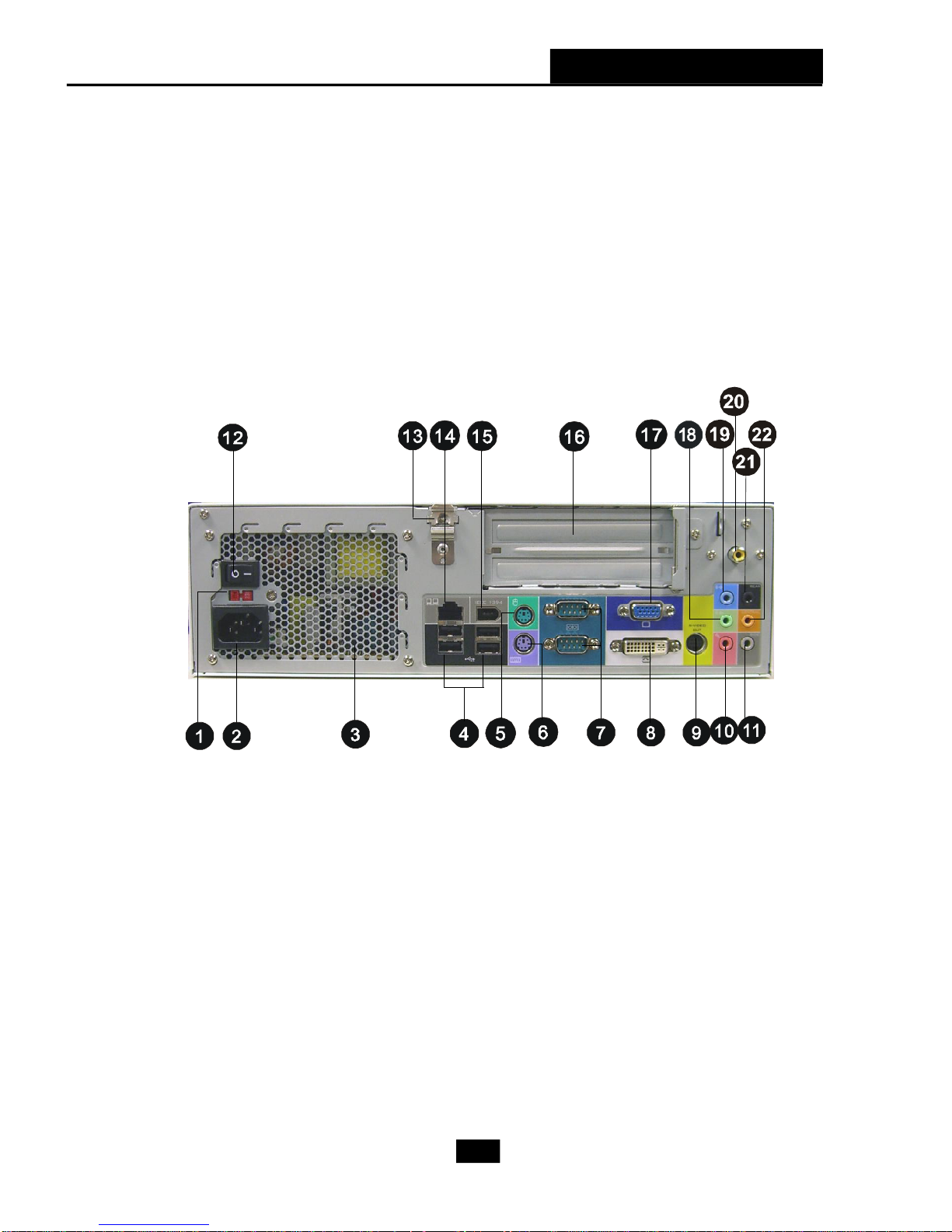
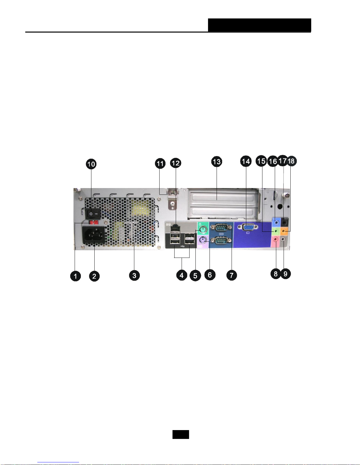
Rear View
Chapter 1 - Getting Started
1. Voltage Selector 12. Power On/Off Switch
2. Power Jack 13. Support Bracket Spring
3. Ventilation Hole 14. RJ-45 LAN Jack
4. 4 x USB 2.0 Ports 15. 6-pin IEEE 1394 Port
5. PS/2 Mouse 16. Expansion Slots
6. PS/2 Keyboard 17. VGA Port
7. Serial Ports 18. Line-out
8. DVI Port 19. Line-in
9. S-Video out 20. RCA out
10. Mic-in 21. RS-Out
11. SS-Out 22. C/S-Out
1-5
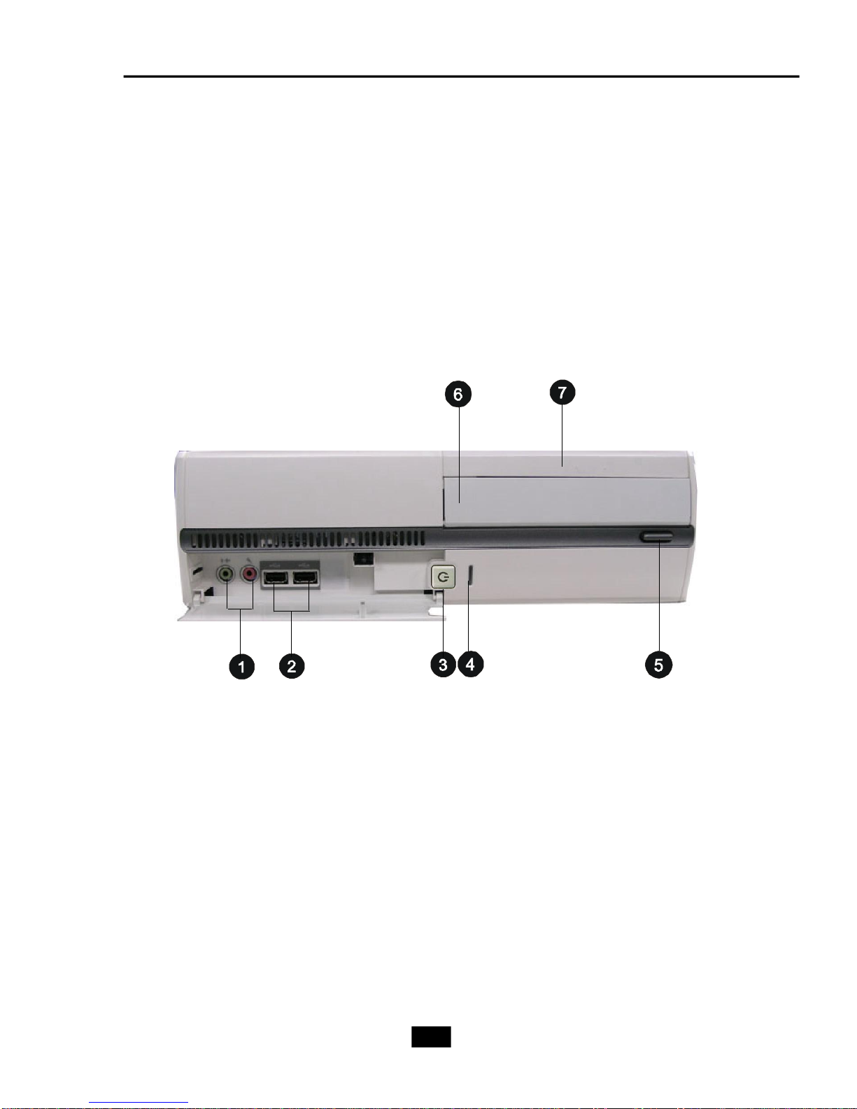
Lite Version
Front View
1. Mic-in (pink), 4. HDD LED
Headphone-out (green) 5. Optical Drive Eject/Close Button
2. 2 x USB 2.0 Ports 6. Optical Drive (optional)
3. Power Button & Power LED 7. Card Reader Drive (optional)
1-6
Rear View
Chapter 1 - Getting Started
1. Voltage Selector 10. Power On/Off Switch
2. Power Jack 11. Support Bracket Spring
3. Ventilation Hole 12. RJ-45 LAN Jack
4. 4 x USB 2.0 Ports 13. Expansion Slots
5. PS/2 Mouse 14. VGA Port
6. PS/2 Keyboard 15. Line-out
7. Serial Ports 16. Line-in
8. Mic-in 17. RS-Out
9. SS-Out 18. C/S-Out
1-7
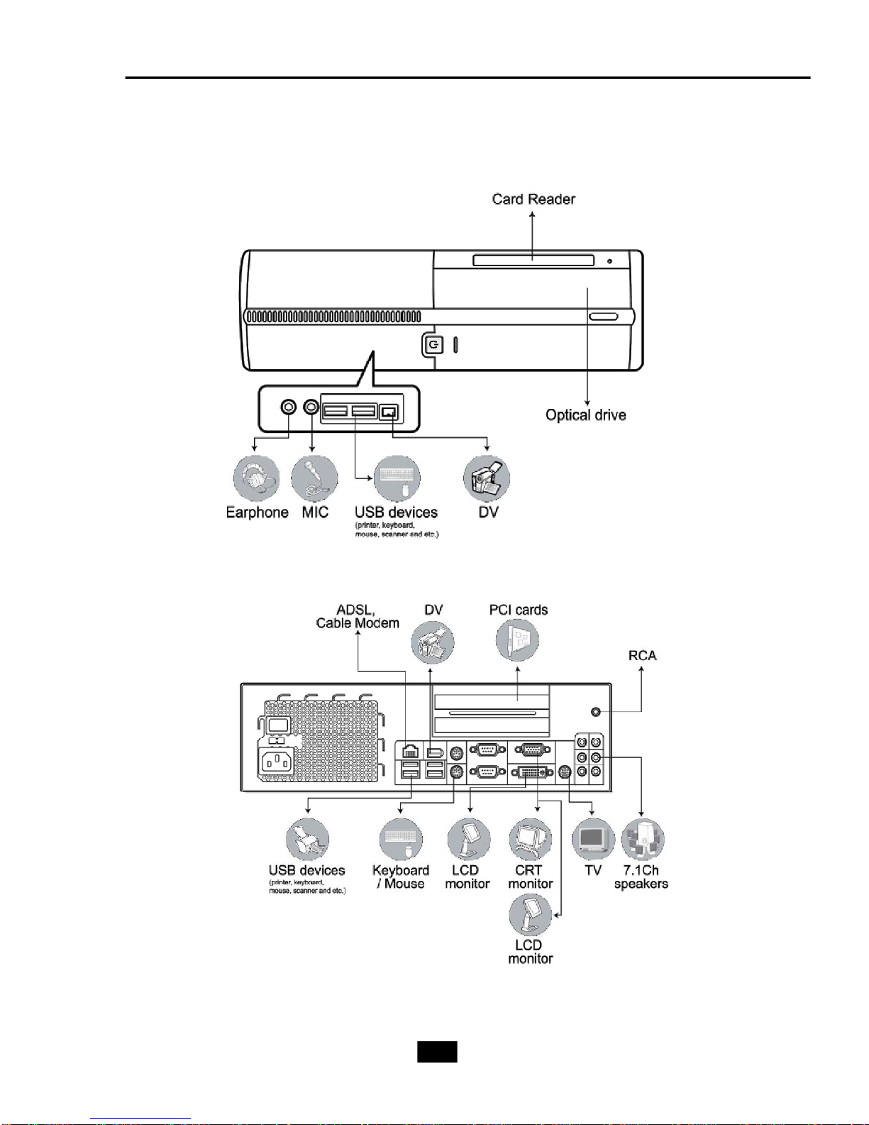
Connecting to External Devices
1-8
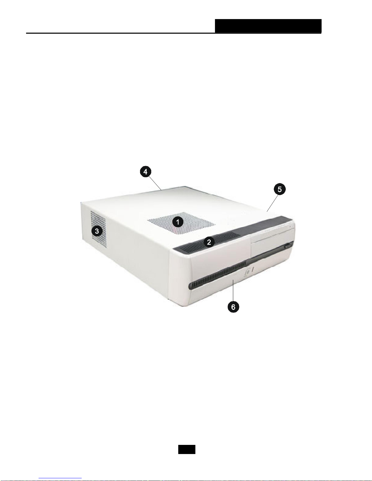
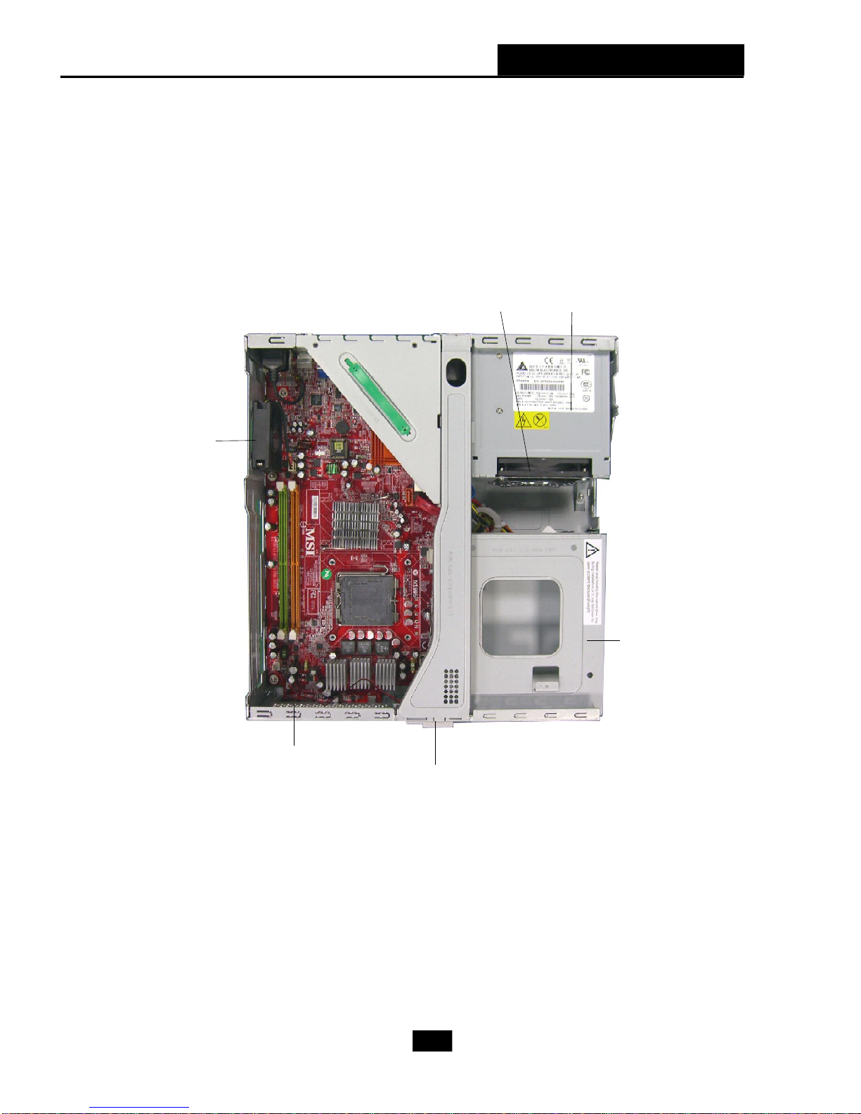
Chassis Design
† Dimension: 330mm (D) x 320mm (W) x 94mm (H)
† Minimized screw structure
† Detachable bay housing
† Multiple ventilation holes
Chapter 1 - Getting Started
1. CPU Fan Ventilation Hole 4. Power Supply Ventilation Hole
2. System Ventilation Hole 5. System Ventilation Hole
3. System Fan Ventilation Hole6. Release Button of Front I/O Door
1-9
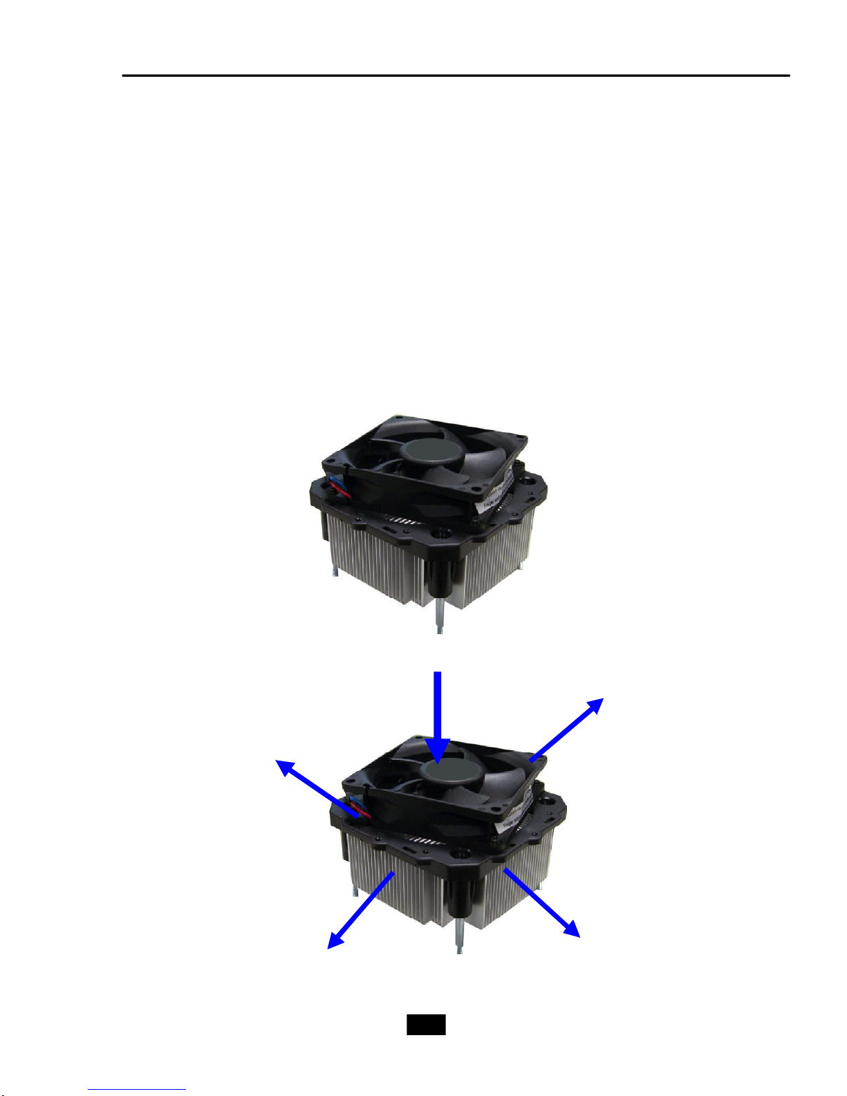
1.3 Thermal Solution
To prevent the system from overheating, we have adopted a specially de-
signed CPU cooler and multiple ventilation holes for better cooling effects.
The specially designed CPU cooler supports Intel® LGA775 processors. The
following figures illustrate how the system fan effectively exhausts hot air through
multiple ventilation holes.
CPU Fan
Air Flow Direction
Air Out
Air In
Air Out
1-10
Chapter 1 - Getting Started
System
Fan
Power
Supply Fan
Power
Supply
Ventilation
Hole
Ventilation
Hole
front panel
1-11

System Air Flow Direction
System Fan
Power
Supply
Fan
Power
Supply
front panel
After the installation is completed,
please keep other objects away from the
ventilation hole at least 2.5cm and above.
Do not block the ventilation hole.
1-12

2
Mainboard Hardware
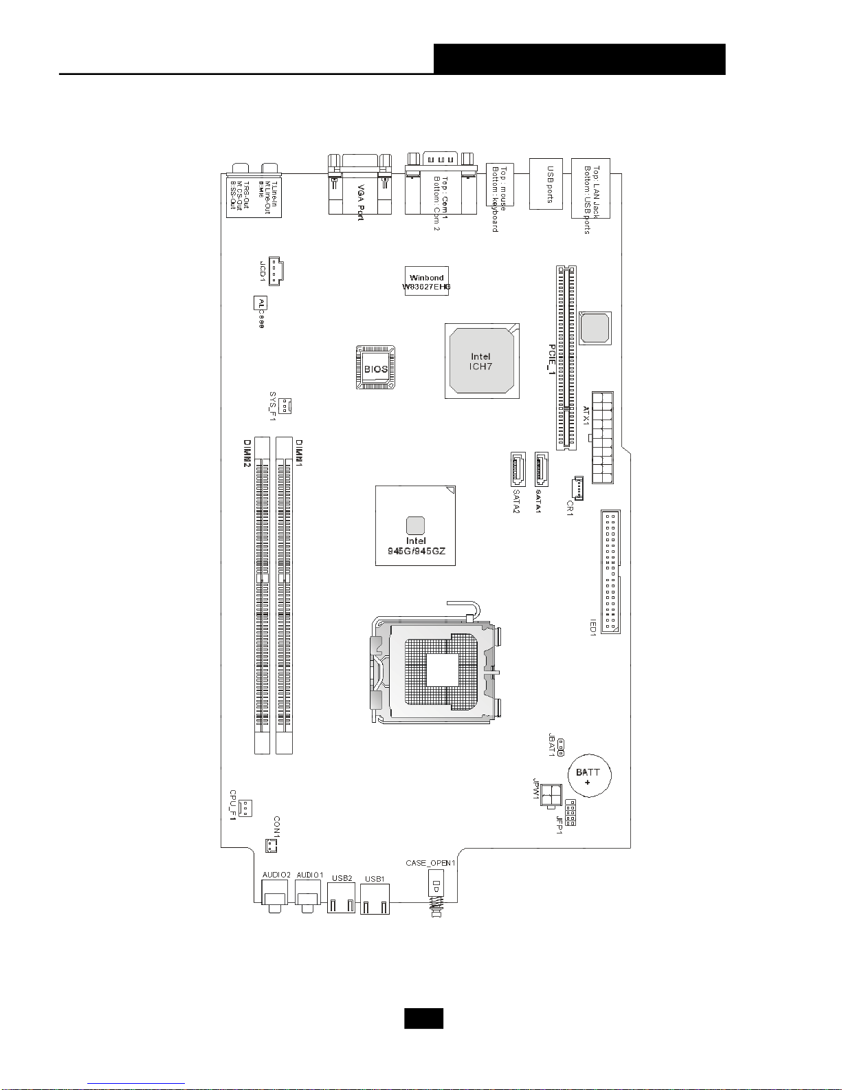
2.1 Mainboard Layout
2.2 CPU
2.3 Memory
2.4 Power Supply
2.5 Front Panel
2.6 Back Panel
2.7 Connectors
2.8 Jumper
2.9 Slots

2.1 Mainboard Layout
MS-7231 (V2.X) Mainboard (Standard Version)
2-2
Chapter 2 - Mainboard Hardware
MS-7231 (V2.X) Mainboard (Lite Version)
2-3
Supports
2.2 CPU
The mainboard supports Intel® Core™ 2 Duo/ Pentium D/ Pentium 4/ Celeron
Series processors. The mainboard uses a CPU socket called LGA775. When you are
installing the CPU, make sure to install the cooler to prevent overheating. If you
do not have the CPU cooler, contact your dealer to purchase and install them before
turning on the computer. (For the latest information about CPU, please visit http://www.
msi.com.tw/program/products/slim_pc/slm/pro_slm_cpu_support.php)
MSI Reminds You...
Overheating
Overheating will seriously damage the CPU and system, always make
sure the cooling fan can work properly to protect the CPU from
overheating.
Replacing the CPU
While replacing the CPU, always turn off the power supply or unplug the
power supply’s power cord from grounded outlet first to ensure the
safety of CPU.
Overclocking
This motherboard is designed to support overclocking. However, please
make sure your components are able to tolerate such abnormal setting,
while doing overclocking. Any attempt to operate beyond product specifications is not recommended. We do not guarantee the damages
or risks caused by inadequate operation or beyond product
specifications.
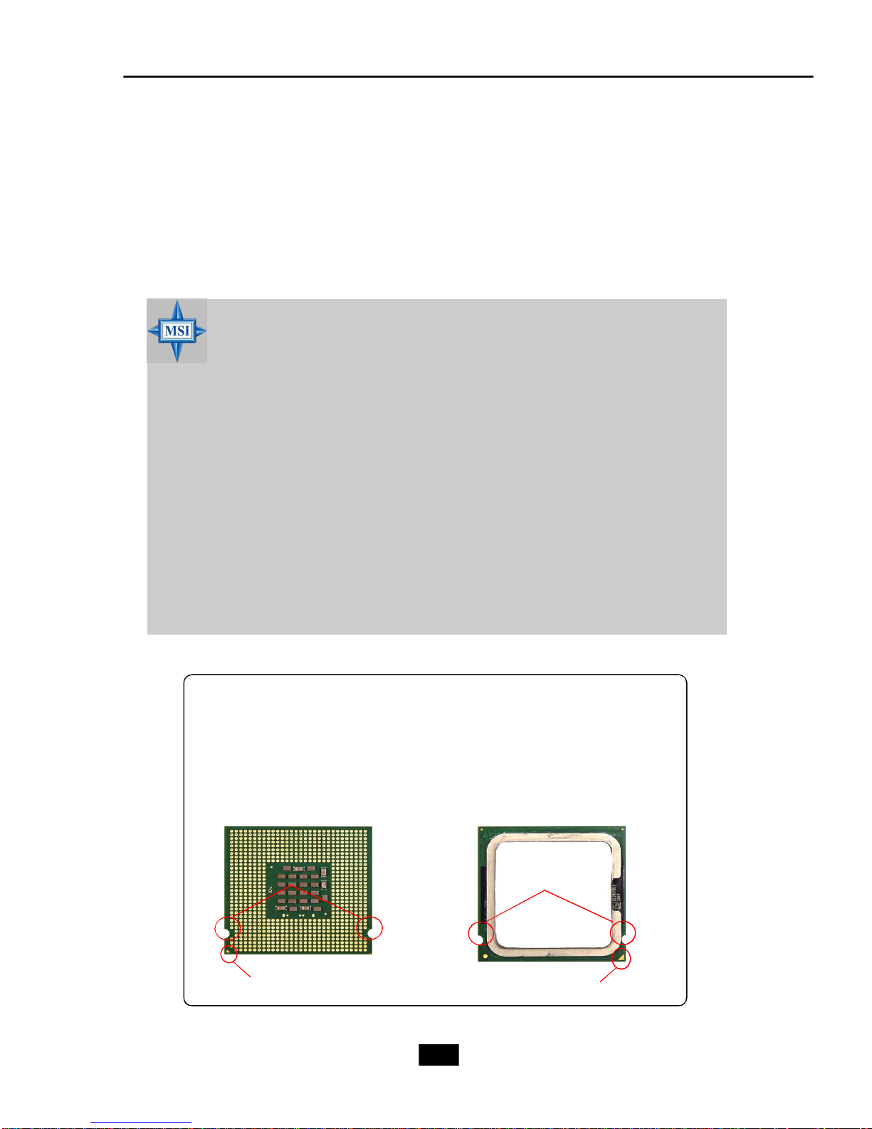
Introduction to LGA 775 CPU
The pin-pad side of LGA 775
CPU.
Alignment
The surface of LGA 775 CPU.
Remember to apply some silicone heat transfer compound
on it for better heat dispersion.
Alignment Key
Yellow triangle is the Pin 1 indicator
Yellow triangle is the Pin 1 indicator
2-4
Chapter 2 - Mainboard Hardware
CPU & Cooler Installation
When you are installing the CPU, make sure the CPU has a cooler attached
on the top to prevent overheating. If you do not have the cooler, contact your
dealer to purchase and install them before turning on the computer. Meanwhile, do not
forget to apply some silicon heat transfer compound on CPU before installing the heat
sink/cooler fan for better heat dispersion.
Follow the steps below to install the CPU & cooler correctly. Wrong installation
will cause the damage of your CPU & mainboard.
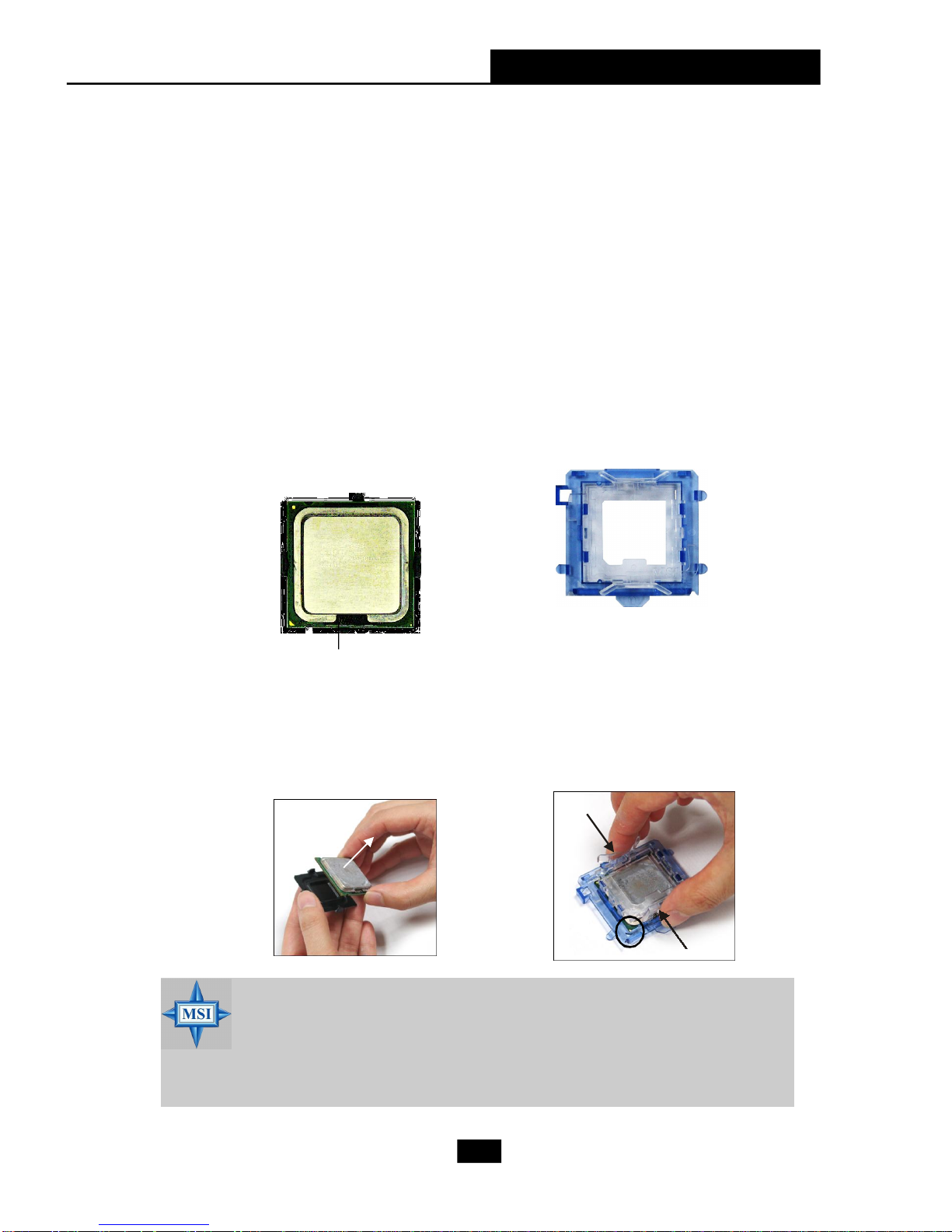
1.The CPU has a land side cover on
the bottom to protect the CPU contact from damage. Rotate it to make
the pin 1 indicator (yellow triangle)
in the right-bottom corner.
land side cover
3.Use 2 hands to remove the land side
cover (if any). Please note not to
touch the pins.
2.Take out the accompanying CPU Clip
and rotate it for the same direction as
the CPU (Pin 1 indicator is in the leftbottom corner).
4.Align the two pin 1 indicators (the
triangles on the CPU & the CPU Clip),
and use the CPU Clip to clip the CPU
up, pressing the clips on both sides
to the center, as the arrows shown.
MSI Reminds You...
1.Confirm if your CPU cooler is firmly installed before turning on your
system.
2.Do not touch the CPU socket pins to avoid damaging.
3. The availability of the CPU land side cover depends on your CPU
packing.
2-5
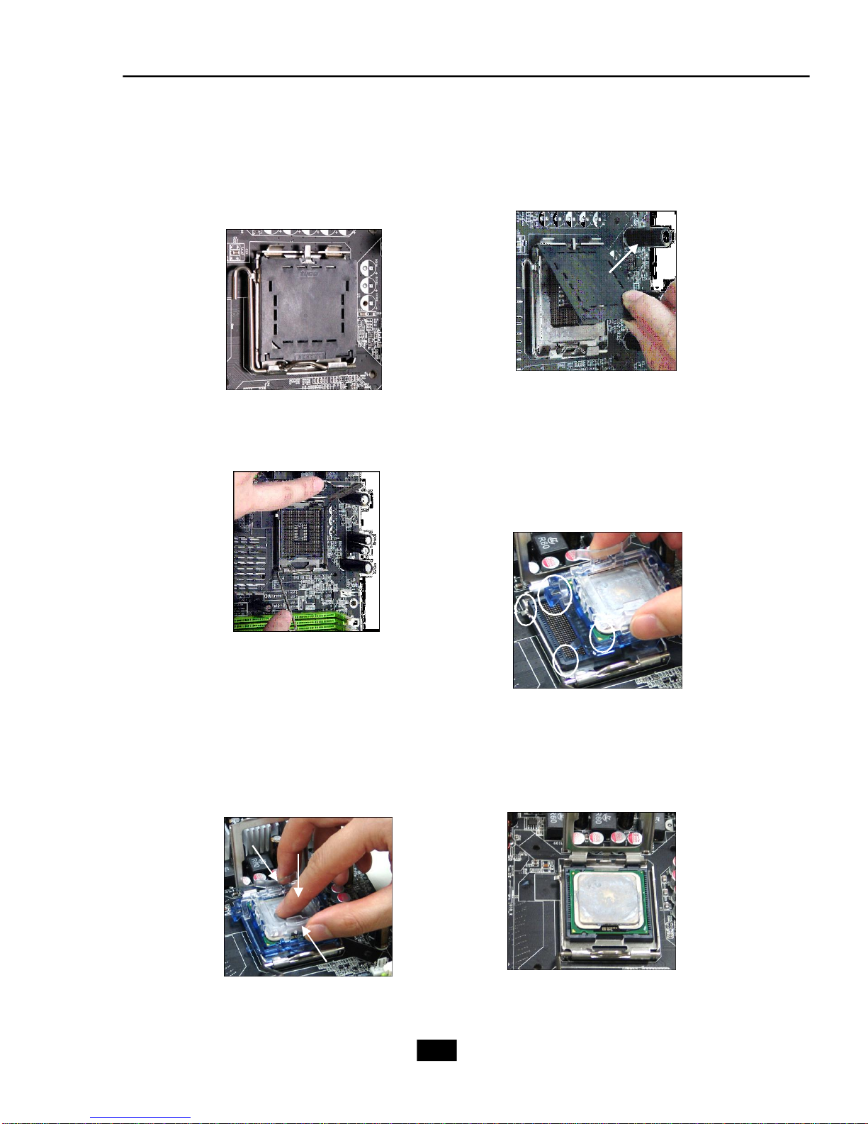
5.The CPU socket has a plastic cap on
it to protect the contact from damage.
Before you have installed the CPU,
always cover it to protect the socket
pin.
6.Remove the cap from lever
hinge side (as the arrow
shows). The pins of socket
reveal.
7.Lift the load lever up and open the
load plate.
9.Use your thumb and the middle fin-
gers to push the clips to release the
CPU, then press down the CPU with
your index finger to allow the whole
module to be installed onto the CPU
socket.
8.Correctly align the triangle of
CPU Clip with the CPU chamfer,
and the square on the CPU Clip
to the hook of the socket.
10.The CPU is installed well on
the CPU socket.
2-6

Chapter 2 - Mainboard Hardware
11.Visually inspect if the CPU is seated
well into the socket, then remove the
CPU Clip with 2 fingers. Then cover
the load plate onto the package.
13. Align the holes on the mainboard
with the heatsink. Lock the
cooler until its four screws fixed
on the mainboard.
12. Press down the load lever
lightly onto the load plate, and
then secure the lever with the
hook under retention tab.
Note:If you want to uninstall the
CPU, align the 4 points (see
Point 8 for details) again and
push the clip to lift up the CPU.
MSI Reminds You...
1.Check the information in BIOS Chapter for the CPU temperature.
2. Whenever CPU is not installed, always protect your CPU socket pin
with the plastic cap covered to avoid damaging.
3. Please note that the mating/unmating durability of the CPU is 20
cycles. Therefore we suggest you do not plug/unplug the CPU too
often.
2-7
 Loading...