

MSI MS-6378 ATX, MS-6378 User Manual
MSI
MICRO-STAR INTERNATIONAL
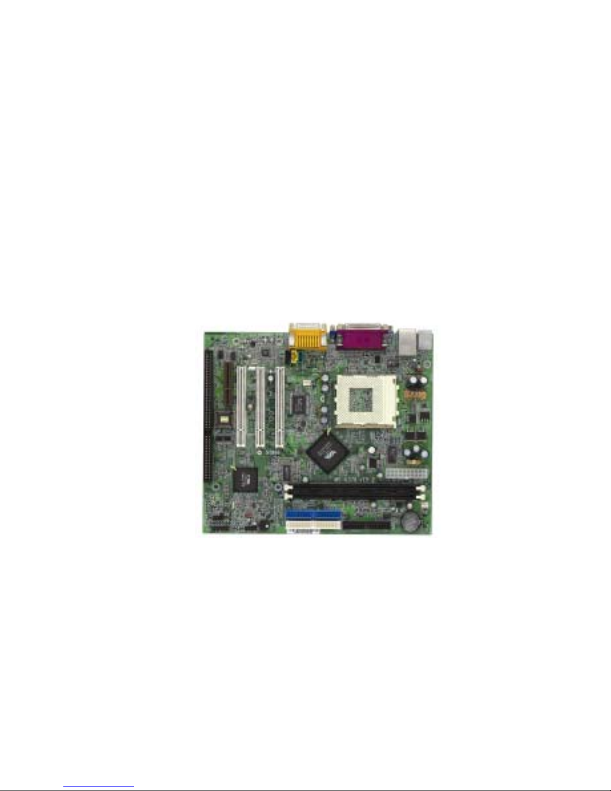
MS-6378 ATX Mainboard
Version 2.0
G52-MA00432
i
Manual Rev: 2.0
Release Date: July 2001
FCC-B Radio Frequency Interference Statement
This equipment has been tested and found to comply with the limits for a
class B digital device, pursuant to part 15 of the FCC rules. These limits are
designed to provide reasonable protection against harmful interference
when the equipment is operated in a commercial environment. This
equipment generates, uses and can radiate radio frequency energy and, if
not installed and used in accordance with the instruction manual, may cause
harmful interference to radio communications. Operation of this equipment
in a residential area is likely to cause harmful interference, in which case
the user will be required to correct the interference at his own ex pense.
Notice 1
The changes or modifications not expressly approved by the party
responsible for compliance could void the user's authority to operate the
equipment.
Notice 2
Shielded interface cables and A.C. power cord, if any, must be used in
order to comply with the emission limits.
VOIR LA NOTICE D'INSTALLATION AVANT DE RACCORDER
AU RESEAU.
ii
Micro-Star International MS-6378
For Home or Office Use
Tested to comply
with FCC Standard

Edition
July 2001
Copyright Notice
The material in this document is the intellectual property of MICRO-
STAR INTERNATIONAL. We take every care in the preparation of
this document, but no guarantee is given as to the correctness of its
contents. Our products are under continual improvement and we reserve
the right to make changes without notice.
Trademarks
All trademarks used in this manual are the property of their respective
owners.
AMD, Athlon and Duron are registered trademark of AMD Corporation.
PS/2 and OS/2 are registered trademarks of IBM Corporation.
Windows 95 and Windows NT are registered trademarks of Microsoft.
Netware is a registered trademark of Novell.
Award is a registered trademark of Award Software Inc.
Revision History
Revision Revision History Date
2.0 First Release for PCB2.X July 2001
Modify BIOS & VGA driver
iii

Safety Instructions
1. Always read the safety instructions carefully.
2. Keep this User’s Manual for future reference.
3. Keep this equipment away from humidity.
4. Lay this equipment on a reliable flat surface before setting it up.
5. The openings on the enclosure are for air convection hence protects the
equipment from overheating. DO NOT COVER THE OPENINGS.
6. Make sure the voltage of the power source and adjust properly
110/220V before connecting the equipment to the power inlet.
7. Place the power cord such a way that people can not step on it. Do not
place anything over the power cord.
8. Always Unplug the Power Cord before inserting any add-on card or
module.
9. All cautions and warnings on the equipment should be noted.
10. Never pour any liquid into the opening that could damage or cause
electrical shock.
11. If any of the following situations arises, get the equipment checked by
a service personnel:
• The power cord or plug is damaged
• Liquid has penetrated into the equipment
• The equipment has been exposed to moisture
• The equipment has not work well or you can not get it work
according to User’s Manual.
• The equipment has dropped and damaged
• If the equipment has obvious sign of breakage
12. DO NOT LEAVE THIS EQUIPMENT IN AN ENVIRONMENT
UNCONDITIONED, STORAGE TEMPERATURE ABOVE 60
0
C
(140
0
F), IT MAY DAMAGE THE EQUIPMENT.
CAUTION: Danger of explosion if battery is incorrectly replaced.
Replace only with the same or equivalent type recommended by the
manufacturer.
iv

v
Contents
Chapter 1. Introduction ...............................................................1-1
Mainboard Specification ............................................................1-2
Mainboard Layout .....................................................................1-4
Quick Components Guide .........................................................1-5
Key Features ............................................................................1-6
MSI Special Features................................................................1-7
PC Alert™ III .......................................................................1-7
Chapter 2. Hardware Setup ........................................................2-1
Central Processing Unit: CPU ...................................................2-2
CPU Installation Procedures ...............................................2-2
CPU Core Speed Derivation Procedure................................2-4
CPU Clock Frequency Selection: JFSB1 ............................2-4
Memory ....................................................................................2-5
Introduction to SDRAM .......................................................2-5
DIMM Modules Combination ...............................................2-6
Installing DIMM Modules .....................................................2-6
Power Supply............................................................................2-7
A TX 20-Pin Power Supply....................................................2-7
Back Panel ...............................................................................2-8
Mouse Connector................................................................2-8
Keyboard Connector ...........................................................2-9
USB Connectors .................................................................2-9
Parallel Port Connector .....................................................2-10
Serial Port Connector: COM 1........................................... 2-11
VGA DB 15 Pin Connector................................................ 2-11
Joystick/Midi Connectors ..................................................2-12
Audio Port Connectors ......................................................2-12
LAN Jack (RJ-45) ..............................................................2-12
Connectors .............................................................................2-13

vi
Floppy Disk Drive Connector: FDD1 ..................................2-13
USB Front Panel Connector: USB1...................................2-13
Hard Disk Connectors: IDE1 & IDE2 ................................. 2-14
Case Connector: JFP1 ......................................................2-15
Wake On Ring Connector: JMDM1 ...................................2-17
Wake On LAN Connector: JWOL1 ....................................2-17
Fan Power Connectors: C_F AN1/S_F AN...........................2-18
CD-In/Aux Line-In/Modem-In Connector: CD_IN/AUX_IN/
MODEM_IN.......................................................................2-19
Chassis Intrusion Switch Connector: JCASE ....................2-20
IrDA Infrared Module Connector: JIR1 ................................2-20
Front Panel Audio Connector: JAUD1 ...............................2-21
Jumpers ..................................................................................2-22
Clear CMOS Jumper: JBA T1 .............................................2-22
Onboard Audio Codec Jumper: JP1...................................2-23
USB Keyboard Wake-up Jumpers: JBV1 & JBV2 ............. 2-24
Slots .......................................................................................2-25
PCI Slots ..........................................................................2-25
CNR (Communication Network Riser) Slot ........................2-25
ISA Slot (Optional) ............................................................2-25
PCI Interrupt Request Routing ........................................... 2-26
Chapter 3. AWARD® BIOS Setup................................................3-1
Entering Setup ..........................................................................3-2
Control Keys .............................................................................3-2
Getting Help..............................................................................3-3
The Main Menu .........................................................................3-4
Standard CMOS Features .........................................................3-6
Advanced BIOS Features ..........................................................3-9
Advanced Chipset Features .................................................... 3-13
Integrated Peripherals .............................................................3-17

vii
Power Management Setup ......................................................3-22
PnP/PCI Configurations...........................................................3-28
PC Health Status ....................................................................3-31
Frequency/V oltage Control ......................................................3-32
Load Fail-Safe/Optimized Defaults ..........................................3-33
Set Supervisor/User Password ................................................ 3-35
Save & Exit Setup...................................................................3-37
Exit Without Saving.................................................................3-38
Chapter 4. Installing Drivers .......................................................4-1
System Requirements...............................................................4-2
VIA® Chipset ............................................................................4-3
Features .............................................................................4-3
VIA Chipset Driver Installation .............................................4-3
VIA KLE133 VGA Driver Installation ....................................4-5
VIA AC97 PCI Sound Driver Installation...............................4-5
Realtek® 8100 Fast Ethernet Controller ....................................4-8
Features .............................................................................4-8
Driver Installation.................................................................4-8
Glossary............................................................................................ I

Introduction
1-1
Chapter 1.
Introduction
The MS-6378 Micro-ATX mainboard is a high-performance computer
mainboard based on VIA Apollo KLE133 chipset and designed for the
AMD® Athlon™ or Duron™ processor for inexpensive business/personal
desktop markets.
The Apollo KLE133 chipset consists of the VT8361 North Bridge
controller and the VT82C686B South Bridge controller. The VT8361 integrates rich AGP4X graphics capabilities for 2D/3D software and internet
multimedia applications. It supports CPU running at a 200/266MHz FSB
frequency; and provides bandwidth and performance for internet and 3D
graphics needs by supporting advanced memory technologies PC133
SDRAM and VC133 RAM (Virtual Channel RAM) up to 1.0GB.
The VIA® VT82C686B Super I/O PCI integrated Peripheral Controller
(PSIPC) includes PCI-to-ISA bridge controller, 10/100 BaseT Ethernet
controller, AC’97 audio and MC’97 modem (for CNR slot). In addition, it
supports dual bus-master IDE with Ultra DMA 33/66/100, four USB ports,
system hardware monitoring and enhanced power management capabilities.
The KLE133 chipset allows the MS-6378 mainboard to meet specific
needs of internet multimedia and 3D graphics applications.
This chapter includes the following topics:
Mainboard Specification 1 -2
Mainboard Layout 1-4
Quick Components Guide 1 - 5
Key Features 1-6
MSI Special Features 1 -7
1

Chapter 1
1-2
CPU
z Supports Socket 462 for AMD® Athlon™ /Duron™ processor
z Supports CPU frequencies at 600/650/700/750/800/850/900/950MHz, 1GHz
and up to 1.3GHz
Chipset
z VIA® VT8361 chipset (552 BGA)
- FSB @200/266MHz
- Integrated Trident Blade 2D/3D video accelerator
- PCI advanced high performance memory controller
- Supports PC100/133 SDRAM, VCM & ESDRAM technology
z VIA® VT686B chipset (352 BGA)
- Enhanced Power Management Features
- Integrated Super I/O (FDC, LPT, COM 1/2 and IR)
- Dual bus Master IDE Ultra DMA 33/66/100
- Integrated Hardware Soundblaster
- Direct Sound AC97 Audio
- ACPI
Clock Generator
z Supports 100/133MHz clocks
Main Memory
z Supports four memory banks using 168-pin unbuffered DIMM
z Supports a maximum memory size of 1GB (256 MB DRAM technology)
z Supports 3.3V SDRAM DIMM
Slots
z One CNR (Communication Network Riser) slot
z Three 32-bit Master PCI Bus slots
z Supports 3.3V/5V PCI bus Interface
z One ISA slot (optional)
On-Board IDE
z An IDE controller on the VIA® VT82C686B chipset provides IDE HDD/
CD-ROM with PIO, Bus Master and Ultra DMA 33/66/100 operation
Mainboard Specification

Introduction
1-3
modes
z Can connect up to four IDE devices
Audio
z Audio controller integrated in 686B chipset
z Software audio codec ALC100P
- Onboard Front Audio Pin Header
Network (Optional)
z Realtek 8100
On-Board Peripherals
z On-Board Peripherals include:
- 1 floppy port supports 2 FDDs with 360K, 720K, 1.2M, 1.44M and
2.88Mbytes
- 1 serial port (COM1)
- 1 parallel port supports SPP/EPP/ECP mode
- 4 USB ports (Rear*2 /Front*2)
- 1 IrDA connector for SIR/CIR/FIR/ASKIR/HPSIR
- 1 VGA port
- 1 Audio/Game port
BIOS
z The mainboard BIOS provides “Plug & Play” BIOS which detects the
peripheral devices and expansion cards of the board automatically.
z The mainboard provides a Desktop Management Interface (DMI) func-
tion which records your mainboard specifications.
Dimension
z Micro-ATX Form Factor: 24.3cm (L) x 21.5cm (W)
Mounting
z 6 mounting holes
Chapter 1
1-4
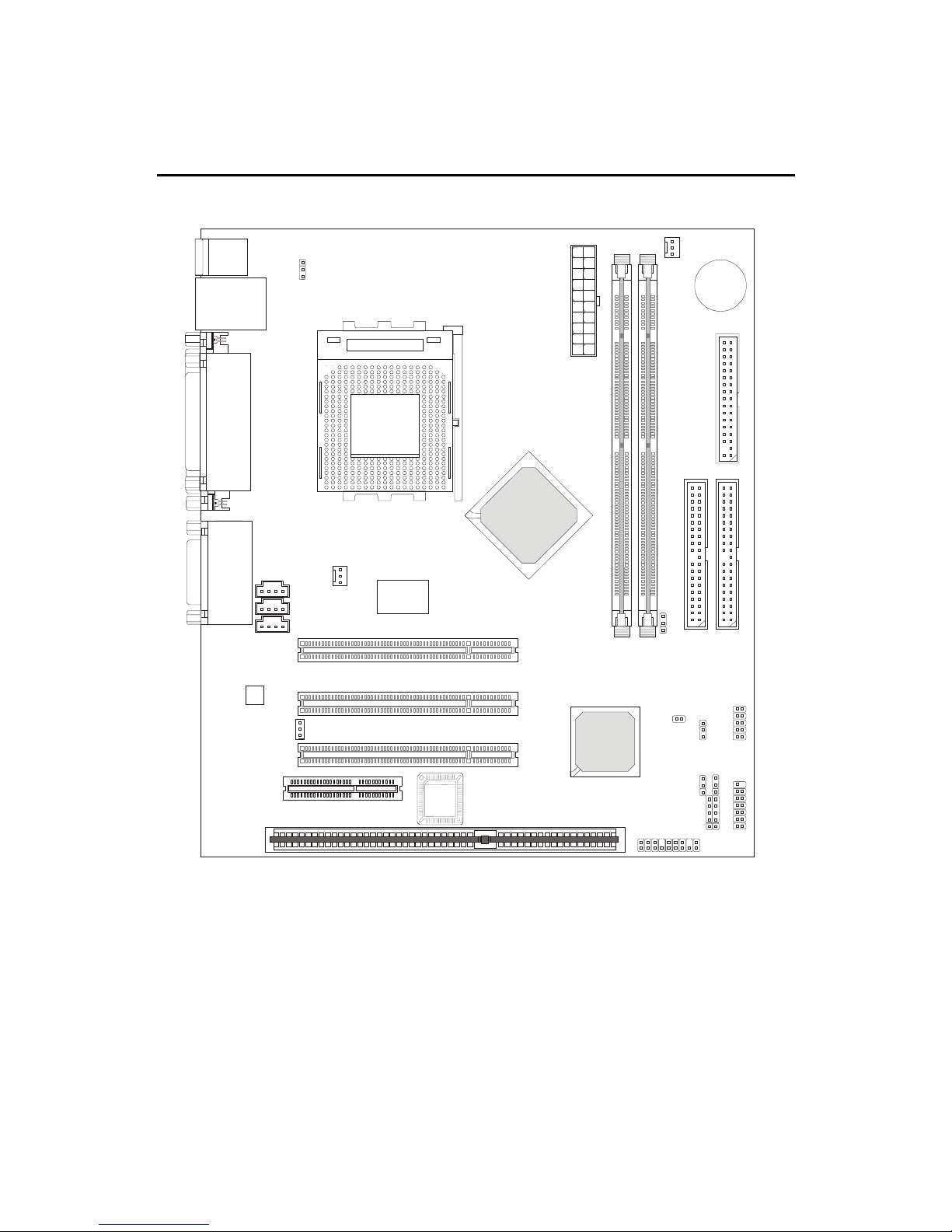
Mainboard Layout
MS-6378 Micro-A TX Mainboard
SOCKET 462
Top : Pa rallel Port
Bottom:
COM Port &
VGA Port
BATT
+
BIOS
VIA
VT82C686B
PCI Slot 1
PCI Slot 2
PCI Slot 3
VIA
VT8361
RTL 8100
(Optional)
I
D
E
1
I
D
E
2
F
D
D
1
D
I
M
M
1
D
I
M
M
2
CNR
JCASE
C_FAN1
A
T
X
P
o
w
e
r
S
u
p
p
l
y
J
B
V
1
J
F
S
B
1
J
M
D
M
1
J
I
R
1
J
B
A
T
1
JAUD1
J
P
1
U
S
B
1
J
B
V
2
J
F
P
1
Top : mouse
Bottom: keyboard
Top: LAN Jack (Optional)
Bottom: USB
ports
CD_IN
JWOL1
Codec
MODEM_IN
S_FAN
AUX_IN
Top :
Game port
Bottom:
Line-Out
Line-In
Mic
ISA Slot
(Optional)

Introduction
1-5
Quick Components Guide
Component Function Reference
DIMM 1~2 Installing memory modul es See p. 2-5~2-6
Socket 462 Installing CPU See p. 2-2~2-3
C_FAN1 Connecting to CPUFAN See p. 2-18
S_FAN Connecting to SYSF AN See p. 2-18
ATX Power Supply Installing power supply See p. 2-7
IDE1& IDE2 Connecting to IDE hard dis k dr ive See p.2-14
FDD1 Connecting to floppy disk drive See p.2-13
USB1 Connecting to USB interfaces See p. 2-13
PCI Slot 1~3 Installing expansion cards See p. 2-25
CNR Slot Installing expansion cards See p. 2-25
JFP1 Connecting to the case See p. 2-15
JMDM1 Connecting to a modem card See p. 2-17
JWOL1 Connecting to an LAN card See p. 2-17
JIR1 Connecti ng to IrDA infrared module See p. 2-20
JAUD1 Connecting to Audio connectors See p. 2-21
JBAT1 Clearing CMOS data See p. 2-22
JBV1 & JBV2 Setting keyboard wake-up function See p. 2-24
JP1 Enable onboard audio codec See p. 2-23
JCASE Co nnecting to the chassi s intrusion switc h See p. 2-20
JFSB1 Setting CPU Front Side Bus frequency See p. 2-4

Chapter 1
1-6
Key Features
z Microsoft
®
PC99 compliant
z PC Alert
TM
III system hardware monitor
z CPU: Socket 462 for AMD
®
Athlon™/Duron™ Processor
z Micro-ATX Form Factor
z Clock: 100/133MHz
z Audio integrated in chipset
z Memory: 2 SDRAM DIMMs
z LAN Wake up Function
z Modem (External/Internal) Ring Wake up Function
z I/O: 1 serial port, 1 parallel port, 4 USB ports, 1 floppy port, 1 IrDA
connector, 1 Audio/Game port, 1 VGA port
z Slot: 1 CNR slot, 3 PCI slots, 1 ISA slot (optional)
Introduction
1-7
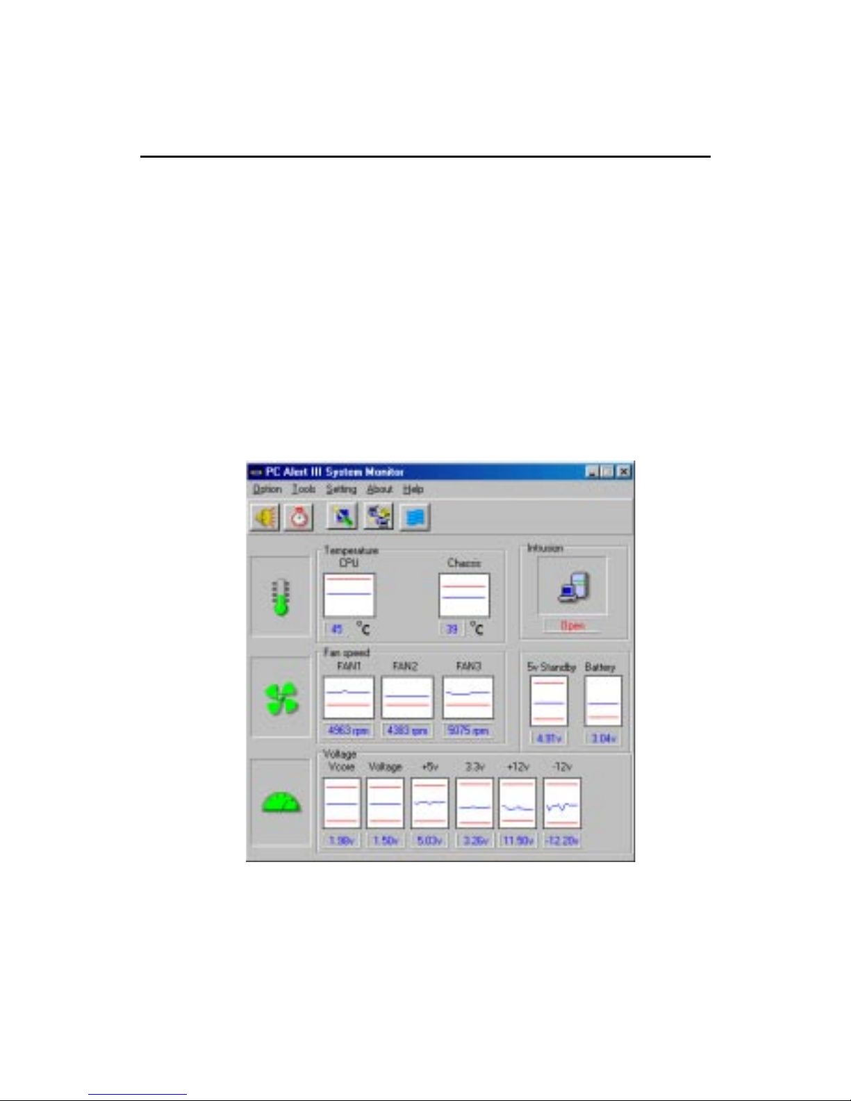
PC Alert™ III
The PC AlertTM III is a utility you can find in the CD-ROM. The utility
is just like your PC doctor that can detect the following PC hardware status
during real time operation:
* monitor CPU & system temperature
* monitor fan speed
* monitor system voltage
* monitor chassis intrusion
If one of the above items is abnormal, the program main screen will be immediately shown on the screen, with the abnormal item highlighted in red. This will
continue to be shown until user disables the warning.
MSI Special Features
Note: Items shown on PC Alert III vary depending on your system’s status.

Chapter 1
1-8
Features:
z Network Management
- Monitoring & remote control
z Basic System Utilities
- Scandisk & Defragment to maintain your HDD
z 3D Graphics Design
- Enables a more friendly user interface
z Sofware Utilities
- SoftCooler Optimized Cooling

Hardware Setup
2-1
Hardware Setup
This chapter provides you with the information about hardware setup
procedures. While doing the installation, be careful in holding the components and follow the installation procedures. For some components, if you
install in the wrong orientation, the components will not work properly.
Use a grounded wrist strap before handling computer components.
Static electricity may damage the components.
This chapter contains the following topics:
Central Processing Unit (CPU) 2-2
Memory 2 -5
Power Supply 2 - 7
Back Panel 2 -8
Connectors 2-13
Jumpers 2-22
Slots 2-25
2
Chapter 2. Hardware Setup
Chapter 2
2-2
Central Processing Unit: CPU
The mainboard supports AMD® Athlon™ and Duron™ processors.
The mainboard uses a CPU socket called Socket A for easy CPU installation.
Make sure the CPU has a Heat Sink and a cooling fan attached on top to
prevent overheating. If you do not find the Heat Sink and cooling fan,
contact your dealer to purchase and install them before turning on the
computer.
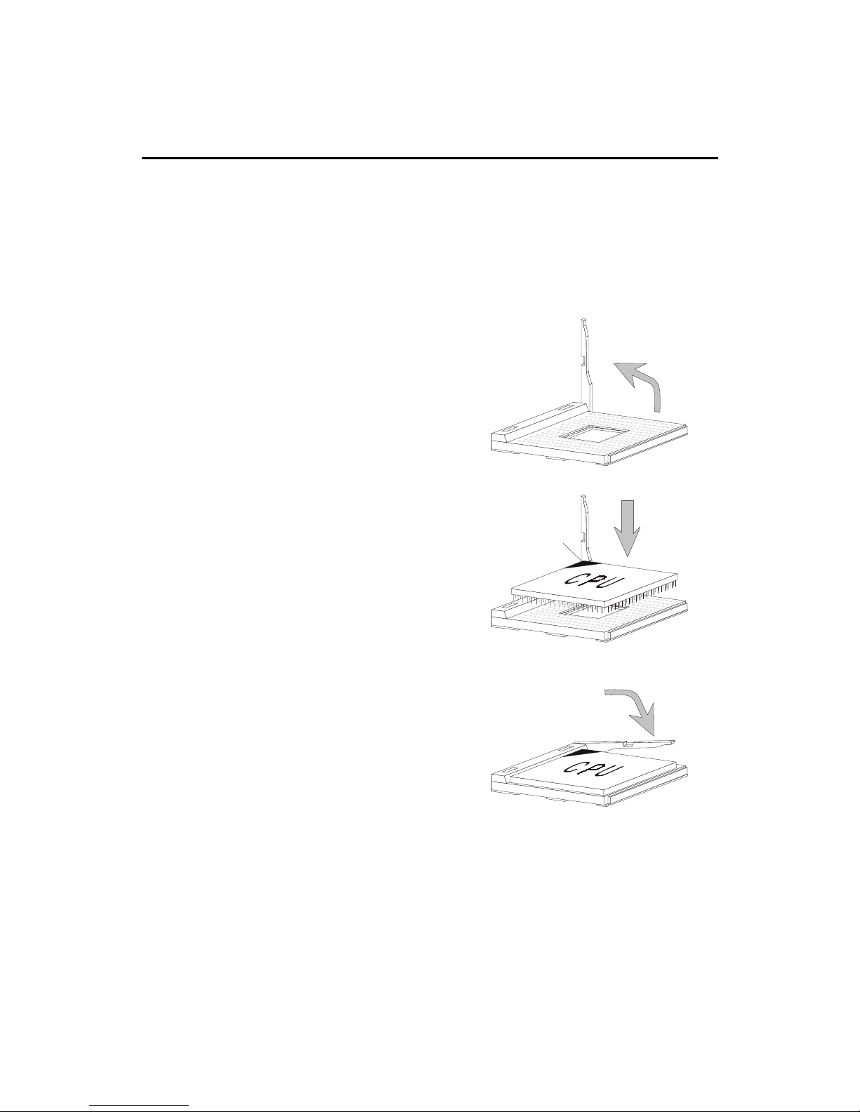
1 . Pull the lever sideways away
from the socket. Then, raise
the lever up to a 90-degree
angle.
2. Look for the cut edge. The
cut edge should point
towards the lever pivot. The
CPU will only fit in the
correct orientation.
3. Hold the CPU down firmly,
and then close the lever to
complete the installation.
CPU Installation Procedures
Open Lever
Cut edge
Sliding
Plate
Close
Lever

Hardware Setup
2-3
Thermal Issue for CPU
As processor technology pushes to faster speeds and higher
performance, thermal management becomes increasingly crucial when building computer systems. Maintaining the proper
thermal environment is key to reliable operation. As such, the
processor must be maintained in the specified thermal requirements. AMD
recommends the use of high performance thermal interface material.
AMD Athlon™/Duron™ processor with a speed of 600MHz and above requires LARGER heatsink and fan. You also need to add thermal grease between the CPU and heatsink to improve heat dissipation. Then, make sure that
the CPU and heatsink are securely fastened and in good contact with each
other. These are needed to prevent damaging the processor and ensuring
reliable operation.
You can check AMD’s web site for more information on proper cooling: http:/
/www.amd.com/products/cpg/athlon/pdf/cooling_guide.pdf
!
W ARNING!
Chapter 2
2-4
CPU Core Speed Derivation Procedure
The mainboard can automatically set the CPU Host Bus Frequency Clock.
If CPU Clock = 100MHz
Core/Bus ratio = 7
then CPU core speed = Host Clock x Core/Bus ratio
= 100MHz x 7
= 700MHz
Overclocking
This motherboard is designed to support overclocking.
However, please make sure your components are able to
tolerate such abnormal setting, while doing overclocking.
Any attempt to operate beyond product specifications is
not recommended. We do not guarantee the damages or
risks caused by inadequate operation or beyond product
specifications.
WARNING!
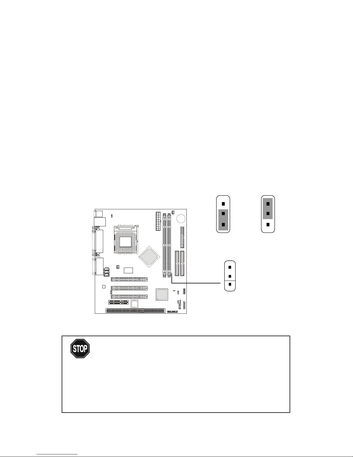
CPU Clock Frequency Selection: JFSB1
Use the jumper to select the appropriate Front Side Bus frequency for
your CPU.
JFSB1
1
133MHz 100MHz
3
1
3
1
Hardware Setup
2-5
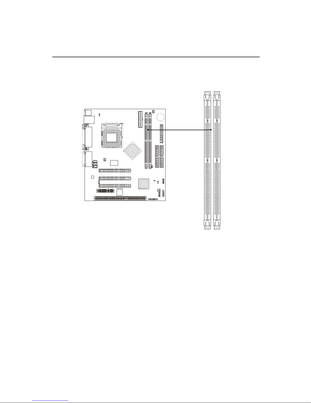
The mainboard supports a maximum memory size of 1GB. It provides
two 168-pin unbuffered SDRAM DIMM (Double In-Line Memory Module)
sockets and supports 256MB technology.
Memory
DIMM1
DIMM2
Introduction to SDRAM
Synchronous DRAM (SDRAM) is a type of dynamic RAM memory
chip that has been widely used starting in the latter part of the 1990s. SDRAMs
are based on standard dynamic RAM chips, but have sophisticated features
that make them considerably faster. First, SDRAM chips are fast enough to be
synchronized with the CPU's clock, which eliminates wait states. Second, the
SDRAM chip is divided into two cell blocks, and data is interleaved between
the two so that while a bit in one block is being accessed, the bit in the other is
being prepared for access. This allows SDRAM to burst the second and
subsequent, contiguous characters at a rate of 10ns, compared to 60ns for the
first character.
SDRAM provides 800 MBps or 1 GBps data transfer depending on
whether the bus is 100MHz or 133MHz.
Chapter 2
2-6
You can install one or more DIMM modules in the following
combination:
DIMM Modules Combination
DIMM Socket Memory Module Total Memory
Socket 1
(Bank 0 & Bank 1)
32MB, 64MB, 128MB,
256MB, 512MB
32MB ~ 512MB
Socket 2
(Bank 2 & Bank 3)
32MB, 64MB, 128MB,
256MB, 512MB
32MB ~ 512MB
Total System Memory 32MB ~ 1GB
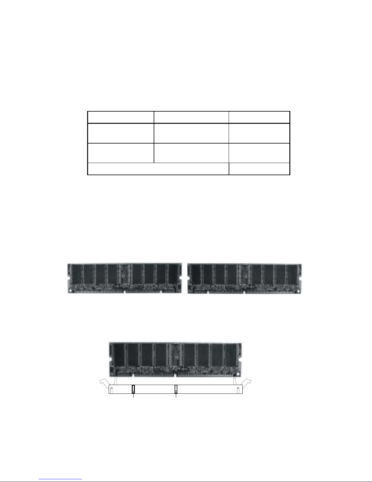
1. The DIMM slot has 2 Notch Keys “VOLT and DRAM”, so the DIMM
memory module can only fit in one direction.
2. Insert the DIMM memory module vertically into the DIMM slot. Then
push it in.
3. The plastic clip at each side of the DIMM slot will automatically
close.
VOLTDRAM
Front View Rear View
Installing DIMM Modules
Hardware Setup
2-7
Power Supply
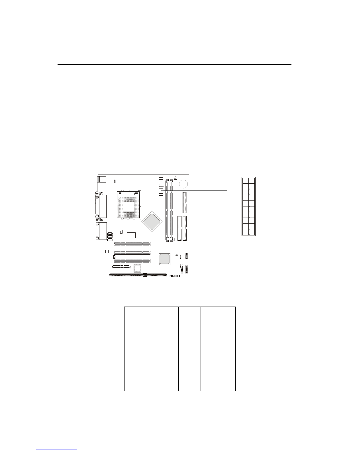
ATX 20-Pin Power Supply
This connector allows you to connect to an ATX power supply. To
connect to the ATX power supply, make sure the power supply connector is
installed in the right orientation and the pins are aligned. Then push down the
power supply connector firmly into the power connector on the mainboard.
ATX
Power Connector
The mainboard supports ATX power supply for the power system.
Before connecting to the power supply, always make sure that all components
are installed properly and no damage will be caused.
10
1
11
20
PIN SIGNAL
11 3.3V
12 -12V
13 GND
14 PS_ON
15 GND
16 GND
17 GND
18 -5V
19 5 V
20 5 V
PIN SIGNAL
1 3.3V
2 3.3V
3 GND
45V
5 GND
65V
7 GND
8 PW_OK
9 5V_SB
10 12V

Chapter 2
2-8
The Back Panel provides the following connectors:
Mouse
Keyboard USB
Parallel
COM 1 V GA L-out L-in
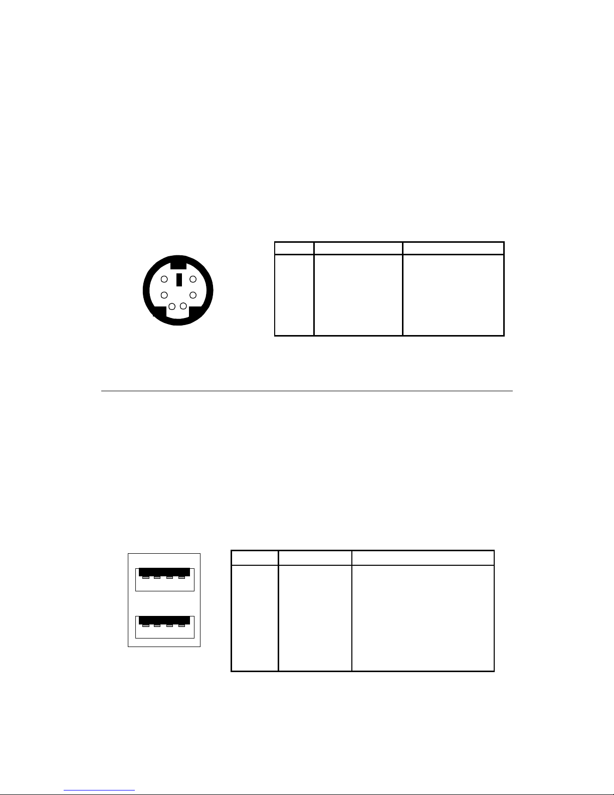
Mouse Connector
The mainboard provides a standard PS/2® mouse mini DIN connector
for attaching a PS/2® mouse. You can plug a PS/2® mouse directly into this
connector.
Back Panel
MIC
Midi/Joystick
PS/2 Mouse (6-pin Female)
2
1
3
4
5
6
PIN SIGNAL DESCRIPTION
1 Mouse DATA Mouse DATA
2 NC No connection
3 GND Ground
4 VCC +5V
5 Mouse Clock Mouse clock
6 NC No connection
Pin Definition
LAN
Hardware Setup
2-9
Keyboard Connector
The mainboard provides a standard PS/2® keyboard mini DIN connector for attaching a PS/2® keyboard. You can plug a PS/2® keyboard directly into
this connector.
USB Connectors
The mainboard provides a UHCI (Universal Host Controller Interface)
Universal Serial Bus root for attaching USB devices such as keyboard, mouse
or other USB-compatible devices. You can plug the USB device directly into
the connector.
21
34
5
6
PS/2 Keyboard (6-pin Female)
PIN SIGNAL DESCRIPTION
1 Keyboard DATA Keyboard DATA
2 NC No connection
3 GND Ground
4 VCC +5V
5 Keyboard Clock Keyboard clock
6 NC No connection
Pin Definition
USB Ports
1 2 3 4
5 6 7 8
PIN SIGNAL DESCRIPTION
1 VCC +5V
2 -Data 0 Negative Data Channel 0
3 +Data0 Positive Data Channel 0
4 GND Ground
5 VCC +5V
6 -Data 1 Negative Data Channel 1
7 +Data 1 Positive Data Channel 1
8 GND Ground
USB Port Description
Chapter 2
2-10
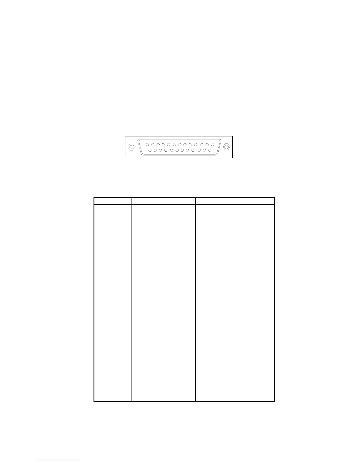
Parallel Port Connector
The mainboard provides a 25-pin female centronic connector for LPT.
A parallel port is a standard printer port that supports Enhanced Parallel Port
(EPP) and Extended Capabilities Parallel Port (ECP) mode.
13
1
1425
PIN SIGNAL DESCRIPTION
1 STROBE Strobe
2 DATA0 Data0
3 DATA1 Data1
4 DATA2 Data2
5 DATA3 Data3
6 DATA4 Data4
7 DATA5 Data5
8 DATA6 Data6
9 DATA7 Data7
10 ACK# Acknowledge
11 BUSY Busy
12 PE Paper End
13 SELECT Select
14 AUTO FEED# Automatic Feed
15 ERR# Error
16 INIT# Initialize Printer
17 SLIN# Select In
18 GND Ground
19 GND Ground
20 GND Ground
21 GND Ground
22 GND Ground
23 GND Ground
24 GND Ground
25 GND Ground
Pin Definition

Hardware Setup
2-11
Serial Port Connector: COM 1
The mainboard has one 9-pin male DIN connector for serial port COM 1.
You can attach a serial mouse or other serial devices.
1 2 3 4 5
6 7 8 9
PIN SIGNAL DESCRIPTION
1 DCD Data Carry Detect
2 SIN Serial In or Receive Data
3 SOUT Serial Out or Transmit Data
4 DTR Data Terminal Ready)
5 GND Ground
6 DSR Data Set Ready
7 RTS Request T o Send
8 CTS Clear T o Send
9 RI Ring Indicate
9-Pin Male DIN Connectors
Pin Definition
VGA DB 15 Pin Connector
The mainboard provides one DB 15-pin female connector to connect a
VGA monitor.
Pin Definition
Analog Video Display Connector (DB-15S)
PIN SIGNAL DESCRIPTION
1 Red
2 Green
3 Blue
4 Not used
5 Ground
6 Ground
7 Ground
8 Ground
9 Power
10 Ground
11 Not used
1 2 SDA
1 3 Horizontal Sync
1 4 Vertical Sync
15 SCL
DB 15-Pin Female Connector
5 1
15 11
Chapter 2
2-12
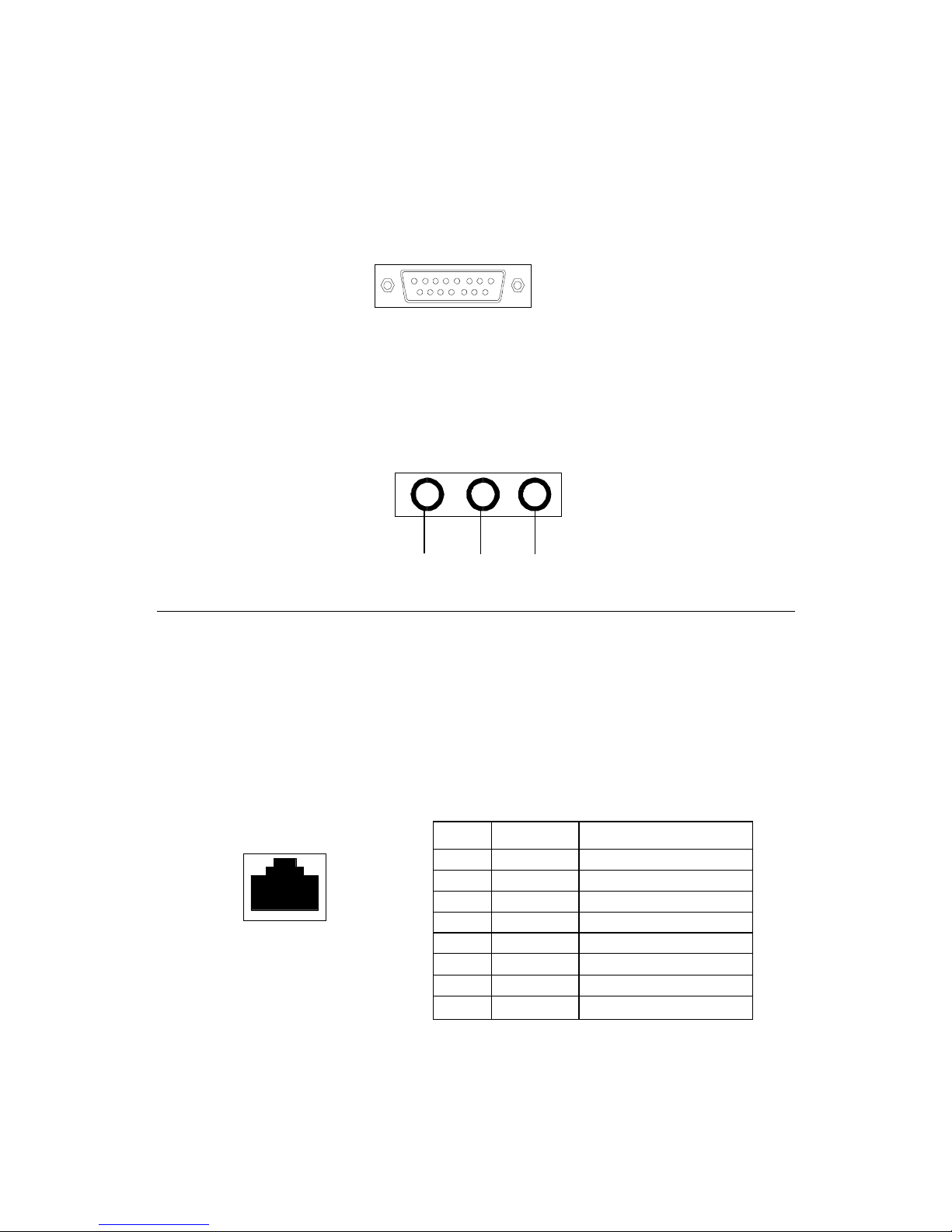
LAN Jack (RJ-45)
The mainboard provides one standard RJ-45 jack for connection to
Local Area Network (LAN). You can connect a network cable to the LAN jack.
LAN RJ-45 Jack
Audio Port Connectors
Line Out is to connect speakers or headphones. Line In is a connector
for external CD player, Tape player or other audio devices. Mic is used to
connect to a microphone.
Line
Out
LineInMIC
Joystick/Midi Connectors
You can connect a joystick or game pad to this connector.
Pin Definition
PIN SIGNAL DESCRIPTION
1 TDP Transmit Differential Pair
2 TDN Transmit Differential Pair
3 RDP Receive Differential Pair
4 NC Not Used
5 NC Not Used
6 RDN Receive Differential Pair
7 NC Not Used
8 NC Not Used
 Loading...