

Mitutoyo Measuring Projector, PJ-A3000, PJ-A3005F-150, PJ-A3010F-200, PJ-A3010F-100 User Manual
...Page 1
No.99MBA043A
SERIES No.302
PJ-A3000 Series
Measuring Projector
User’s Manual
Read this User's Manual thoroughly
before operating the instrument. After reading,
retain it close at hand for future reference.
Page 2
Conventions Used in this User's Manual
This section describes the symbols (safety warning symbols) used in this manual.
Safety Precautions
This manual uses various symbols to help you use this unit correctly, and prevent danger to
personnel or equipment damage.
• The following symbols indicate general dangers, warnings and cautions.
DANGER
Indicates an imminently hazardous situation which, if not avoided, will result in serious
injury or death.
WARNING
Indicates a potentially hazardous situation which, if not avoided, will result in serious
injury or death.
CAUTION
Indicates a potentially hazardous situation which, if not avoided, may result in minor or
moderate injury or property damege.
• The following symbols indicate specific warnings or prohibited actions.
Alerts the user to a specific hazardous situation. The given example means “Caution,
risk of electric shock”.
Prohibits a specific action. The given example means “Do not disassemble”.
No.99MBA043A
i
Page 3
WARNING
Do not modify this instrument.
Risk of fire or electric shock.
Do not bend, twist, pull, or modify the power cord.
Risk of fire or electric shock.
Do not remove the front panel, rear panel, side panel or covers of this
instrument.
Risk of electric shock.
Only operate this instrument at the specified voltage.
Risk of fire or electric shock.
Do not set up this instrument on an unstable bench.
The instrument may fall.
Risk of injury.
Do not place a vessel containing liquid near the instrument.
Risk of fire or electric shock.
Unplug the power cord and contact Mitutoyo if liquid has entered the
instrument.
Risk of fire or electric shock.
Unplug the power cord if replacing a fuse.
Risk of electric shock.
The AC outlet incorporated with the instrument is only available for
Mitutoyo accessories.
Do not plug in other equipment.
Risk of fire.
Should this system be used under abnormal conditions such as heat
radiation, smoking, and nasty smell generation, there is a risk of fire or
electric shock.
Immediately turn off the power switch, then unplug the power plug from
the outlet.
Contact your dealer or the nearest Mitutoyo service network.
No.99MBA043A
ii
Page 4
Unplug the power cord if performing maintenance.
Do not pull the cable to unplug the power cord.
Hold the plug and pull to prevent cord breakage.
Risk of fire or electric shock.
Do not connect/disconnect or touch the plug with wet hands.
Risk of electric shock.
Keep the power cord away from heaters.
Risk of fire or electric shock with melted cable insulation.
Only use the specified fuse.
Risk of fire or electric shock.
Do not block the ventilation outlets.
Risk of fire due to internal heat build up.
For quick power shutoff install this system at a site where the system
power plug can be easily identified and quickly accessed to be
unplugged.
No.99MBA043A
iii
Page 5
CAUTION
CAUTION
Do not apply excessive force to the instrument.
Risk of instrument failure, damage, or decreased accuracy.
Only hold the specified parts of the instrument if transporting.
Risk of instrument failure, damage, or decreased accuracy.
Exercise care so as not to pinch or hurt your fingers if
mounting/dismounting accessories.
Only use the accessories specified in the User’s Manual provided with the
instrument.
Risk of fire, electric shock, and instrument failure.
No.99MBA043A
iv
Page 6

CONVENTIONS USED IN USER'S MANUAL
CONVENTIONS USED IN USER'S MANUAL
On Various Types of NotesOn Various Types of Notes
The Following types of notes are provided to help the operator obtain measurement data
through correct instrument operation.
The Following types of notes are provided to help the operator obtain measurement data
through correct instrument operation.
An important note is a type of note that provides information essential to the
completion of a task. You cannot disregard this note to complete the task.
An important note is a type of note that provides information essential to the
completion of a task. You cannot disregard this note to complete the task.
An important note is a type of precaution, which if neglected could result in a
loss of date, decreased accuracy or instrument malfunction/failure.
An important note is a type of precaution, which if neglected could result in a
loss of date, decreased accuracy or instrument malfunction/failure.
IMPORTANT IMPORTANT
NOTE NOTE
A note emphasizes or supplements important points of the main text. A note
supplies information that may only apply in special cases(e.g.. Memory
limitations, equipment configurations, or details that apply to specific versions
described in the text to their specific needs.
It also provides reference information associated w
described in the text to their specific needs.
It also provides reference information associated w
A note emphasizes or supplements important points of the main text. A note
supplies information that may only apply in special cases(e.g.. Memory
limitations, equipment configurations, or details that apply to specific versions
TIP
A tip is a type of note that helps the user apply the techniques and procedures
ith the topic being
No.99MBA043A
v
TIP
A tip is a type of note that helps the user apply the techniques and procedures
ith the topic being
Mitutoyo assumes no liability to any party for any loss or damage, dir
ect or indirect, caused by use of this instrument not conforming to thi
s manual.
Information in this document is subject to change without notice.
© Copyright Mitutoyo Corporation. All rights reserved.
No.99MBA043A
v
Page 7

Handling Precautions
1. Confirm the input voltage before turning the power switch on
For the input voltage of this microscope, t her e ar e two systems of 100V-system (100
to 120V) and 220V-system (220 to 240V). Connect t he power plug with the plug
socket after conf ir m ing that the rated voltage of the m icroscope corresponds with the
voltage of plug socket.
2. Turn the power sw itch ON or OFF along the order
The counter may display error messages (E51, E52, E53) by the order which turns
the power supply of the microscope main unit and the peripheral equipment such as
personal computer on or off in t he connect ion with some peripher al equipment, when
the peripheral equipment is being connected with the count er unit at RS232C.
Be sure to perform at the following order, when turning the power switch ON or OFF.
• For ON ∙∙∙∙∙ Peripheral equipment Projector main unit
• For OFF ∙∙∙∙ Projector main unit Peripheral equi pment
3. Only use the specified power cord and fuse
Use only the supplied power cord. Replacement fuses must be of t he specified type,
voltage and current.
4. Do not disassemble
Disassembly of any unit or removal of panels may present a hazard to personal or
result in a unit failure. Never att em pt to disassemble, unless absolutely essential, e.g.
for the replacement of a fuse, etc..
This instrument consists of precision components, and its performance cannot be
guaranteed, even within the warranty period, if it is disassembled by the user.
All equipment failures that occur after user disassembly will be repaired on a fee-forservice basis.
Guarantee
This system has been manufactured under Mitutoyo's rigor ous quality control system.
In the event that it proves defective in workmanship or m at erials within one year of the
date of purchase under normal usage, Mitutoyo will repair the instr um ent free of charge.
Contact your dealer or nearest Mitutoyo Service Center.
This guarantee does not apply to the following cases:
Equipment failure or damag e due to incorrect usage or unauthorized modif ication or
repair.
Equipment failure or damage resulting from moving, transporting, or dropping t he
instrument.
Equipment failure or damag e due to fires, salt damage, gas damage, abnormal
voltages, or natural disasters.
No.99MBA043A
vi
Page 8

CONTENTS
Conventions Used in this User's Manual .................................................................1
Safety Precautions.....................................................................................................1
On Various Types of Notes........................................................................................5
Handling precautions.................................................................................................6
Guarantee ....................................................................................................................6
1. Overview ............................................................................................... 1-1
1.1 Outline.................................................................................................................1-1
1.1.1 Name of Each Part ............................................................................................................. 1-1
1.1.2
Control panel..................................................................................................................... 1-2
1.1.3
Angle counter and X, Y counter....................................................................................... 1-3
1.1.4
Power panel....................................................................................................................... 1-4
2. Installation and Setup .......................................................................... 2-1
2.1 Installation ...........................................................................................................2-1
2.1.1 Environmental Conditions................................................................................................ 2-1
2.1.2
Transportation and installation......................................................................................... 2-2
2.1.3
Setting up the main unit.................................................................................................... 2-3
2.1.4
Removing the carrying handles....................................................................................... 2-3
2.2 Assembly.............................................................................................................2-4
2.2.1 Installing the cross-travel stage and Digimatic Head (for PJ-A3005D-50)...................2-4
2.2.2
Installing the cross-travel stage and connecting the Linear Scale cables (PJ-A3010F-200).2-7
2.2.3
Connecting the Optoeye A2 Image Edge Sensor(for PJ-3010F-200).....................2-9
2.2.4 Mounting the projection lens
..........................................................................................2-10
2.2.5
Setting the power voltage............................................................................................2-10
2.2.6
Connecting the power cord .........................................................................................2-11
2.3 Initial Checks (Functional Check)......................................................................2-12
2.3.1 Electrical component connectors................................................................................... 2-12
2.3.2
Main switch (ON-OFF).................................................................................................... 2-12
2.3.3
Switches for Contour illumination and reflected illumination....................................... 2-12
2.3.4
Focusing wheel ............................................................................................................... 2-12
2.3.5
Cross-travel stage........................................................................................................... 2-13
2.3.6
Projection screen ............................................................................................................ 2-13
2.3.7
Others............................................................................................................................... 2-13
2.4 Initial Checks (Performance Check)..................................................................2-14
2.4.1 Checking the position of the contour illumination bulb filament.................................. 2-14
2.4.2
Checking the position of the surface illumination bulb filament.................................. 2-14
2.4.3
Projection with contour illumination............................................................................... 2-16
2.4.4
Projection with reflected illumination............................................................................. 2-17
2.4.5
Color fitter........................................................................................................................ 2-18
2.4.6
Checking the magnification accuracy............................................................................ 2-19
2.4.7
Checking the cross-travel stage travel direction........................................................... 2-21
2.4.8
Checking the cross-travel stage feed error................................................................... 2-23
2.4.9
Checking the resolution (in contour illumination mode)............................................... 2-23
No.99MBA043A
vii
Page 9

2.5 Adjustment ........................................................................................................ 2-24
2.5.1 Adjusting the magnification............................................................................................ 2-24
2.5.2
Aligning the cross-travel stage travel direction to t he cross-hair lines........................ 2-24
2.5.3
Centering the protractor screen..................................................................................... 2-24
3. Operation...............................................................................................3-1
3.1 Projection Lens Selection................................................................................... 3-1
3.1.1 Selecting the projection lens......................................................................................3-1
3.1.2
Replacing the projection lens.................................................................................... 3-2
3.2 Mounting the Workpiece..................................................................................... 3-2
3.3 Focusing and Positioning the Workpiece............................................................ 3-4
3.3.1 Focusing............................................................................................................................. 3-4
3.3.2
Positioning the workpiece................................................................................................. 3-5
3.4 Measurement and Inspection ............................................................................. 3-6
3.4.1 Rectangular coordinate measurement (with the X, Y counter)..................................... 3-6
3.4.2
About parameters ............................................................................................................3-9
3.4.3
Dimensional measurement using a scale..................................................................... 3-15
3.4.4
Comparison with an overlay chart ................................................................................. 3-15
3.4.5
Angle measurement (Using the Angle counter) ...........................................................3-16
4. Troubleshooting....................................................................................4-1
4.1 Main Unit............................................................................................................. 4-1
4.2 Counter Unit........................................................................................................ 4-2
4.3 Error Messages and Remedies.......................................................................... 4-3
4.4 Others................................................................................................................. 4-3
4.4.1 Error is observed in glass scale or overlay chart measurement................................... 4-3
4.4.2
Abnormal cross-travel stage operation, and measurement errors occur.....................4-3
4.4.3
Abnormal protractor screen operation.............................................................................4-4
4.4.4
Partial obscured image..................................................................................................... 4-4
4.4.5
Digimatic Head Key Operation and Counter Display (for PJ-A3005D-50)................... 4-4
5. Maintenance ..........................................................................................5-1
5.1 Maintenance of Optical Components.................................................................. 5-1
5.1.1 Projection lens................................................................................................................... 5-1
5.1.2
Half-reflecting mirror for surface illuminat or....................................................................5-1
5.1.3
Mirror(surface reflecting mirror) ....................................................................................... 5-1
5.1.4
Screen glass...................................................................................................................... 5-1
5.2 Maintenance of Mechanical Components........................................................... 5-2
5.2.1 Projector main unit............................................................................................................ 5-2
5.2.2
Cross-travel stage.............................................................................................................5-2
5.3 Replacing Disposable Parts................................................................................ 5-3
5.3.1 Bulbs for contour and surface illuminators...................................................................... 5-3
5.3.2
Fuse ..................................................................................................................................5-5
5.3.3
Stage glass........................................................................................................................5-6
5.4 Periodic Inspection ............................................................................................. 5-6
5.5 List of Consumable............................................................................................. 5-7
No.99MBA043A
viii
Page 10

6. Specifications....................................................................................... 6-1
6.1 General................................................................................................................6-1
6.1.1 Common Specifications.................................................................................................... 6-1
6.1.2
Individual specifications.................................................................................................... 6-3
6.1.3
Date output(RS232C).................................................................................................. 6-4
6.1.4
Connector specifications.................................................................................................. 6-4
6.1.5
Data output operation....................................................................................................... 6-6
6.1.6
Connecting Micropak........................................................................................................ 6-9
6.1.7
Connecting QM-Data 200............................................................................................... 6-10
6.1.8
Data output (SPC)........................................................................................................... 6-10
6.2 Performance Table for the PJ-A3000 Series Projectors...........................................6-14
6.3 Optical Path.......................................................................................................6-15
6.4 External dimensions..........................................................................................6-16
6.4.1 Main Unit.......................................................................................................................... 6-16
6.4.2
Cross-travel stage........................................................................................................... 6-19
6.5 Accessories.......................................................................................................6-21
6.5.1 Standard accessories..................................................................................................... 6-21
6.5.2
Optional accessories ...................................................................................................... 6-22
SERVICE NETWORK
No.99MBA043A
ix
Page 11

No.99MBA043A
x
MEMO
Page 12
Overview
This chapter describes the system outline, and the name and
function of each part on the PJ-A3000 series Measuring Projector.
1
1.1 Outline
The Mitutoyo PJ-A3000 series Measuring Projector is a multi-purpose measuring microscope for
factory inspection use. It can perform precision measurement of workpiece dimensions, contours
and surface features.
The PJ-A3000 series can be used in a wide range of applications in combination with a variety of
accessories. It is possible to improve the system according to a specific purpose.
The MF-A series has the following features.
• The cross-travel stage with a maximum stroke of 200 X 100mm is available as an option.
• For the counter display, the readout is easy since the characters are large.
• For the counter display unit, following three types are prepared ; angle and X,Y-axis/ only
angle/ no display
• For both the contour and the reflective light source unit, the halogen bulb of 500 hours life with
24V and 150W is used.
• By the slide switching mechanism, the quick bulb exchange is possible.
• The operability is improved still more, because each switches are placed at the front and right
side of main unit.
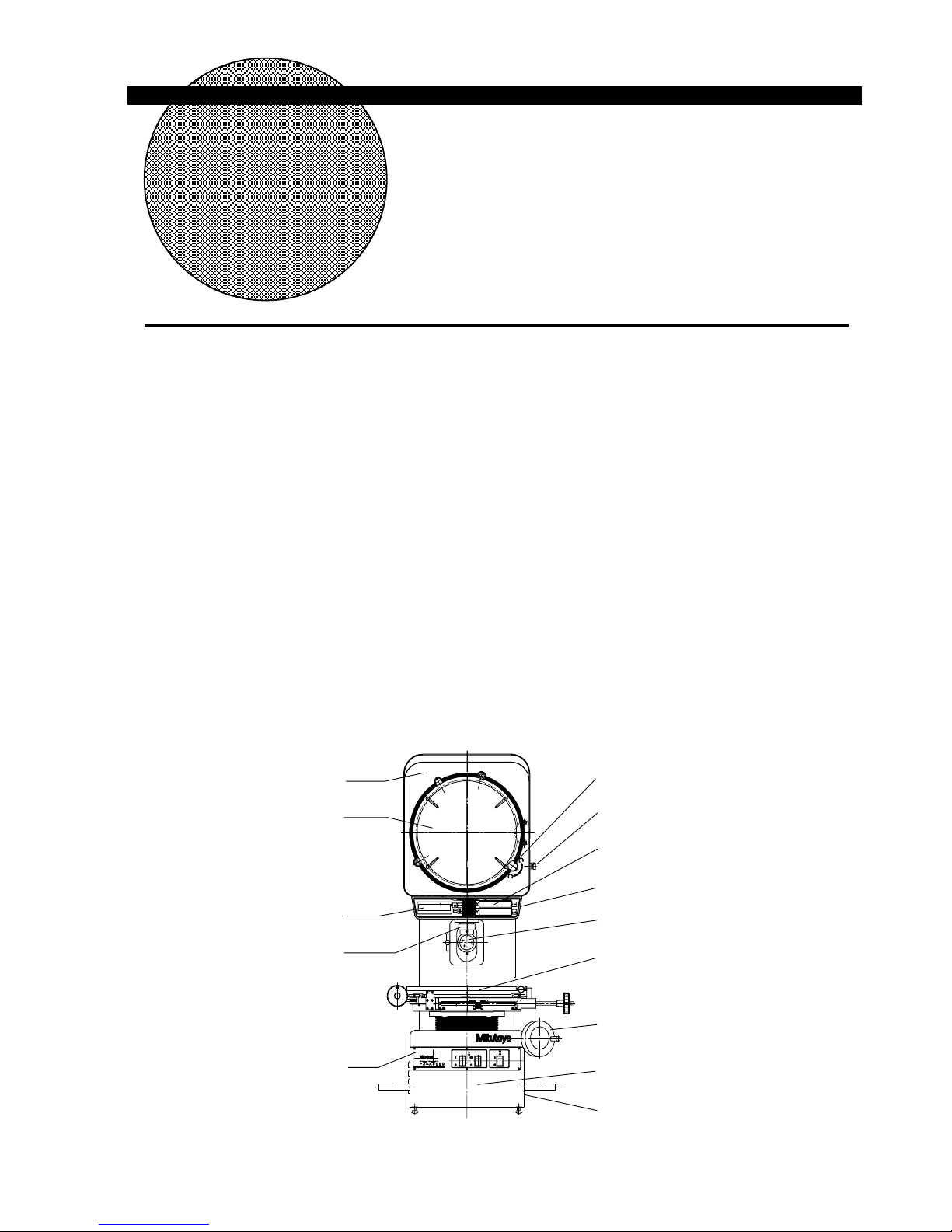
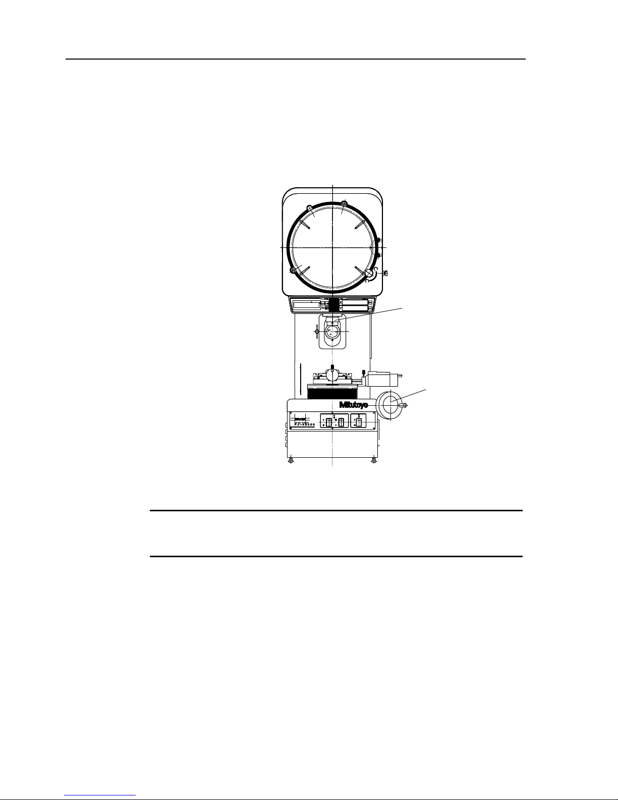
1.1.1 Name of Each Part
[13]
[11]
[12]
[9]
[8]
[14]
[6]
[4]
[3]
[1]
[2]
[5]
[7]
[10]
No.99MBA043A 1 - 1
Page 13
[1] Projector head
[2] Projection screen
[3] Screen rotating knob
[4] Screen clamp knob
[5] Angle counter
[6] XY counter
[7] Projection lens
[8] Reflected illuminator, Condenser lens for reflected illuminator
[9] Cross-travel stage
[10] Control panel
[11] Contour illuminator (interior)
[12] Focusing wheel
[13] Power panel
[14] XY counter out put connect or
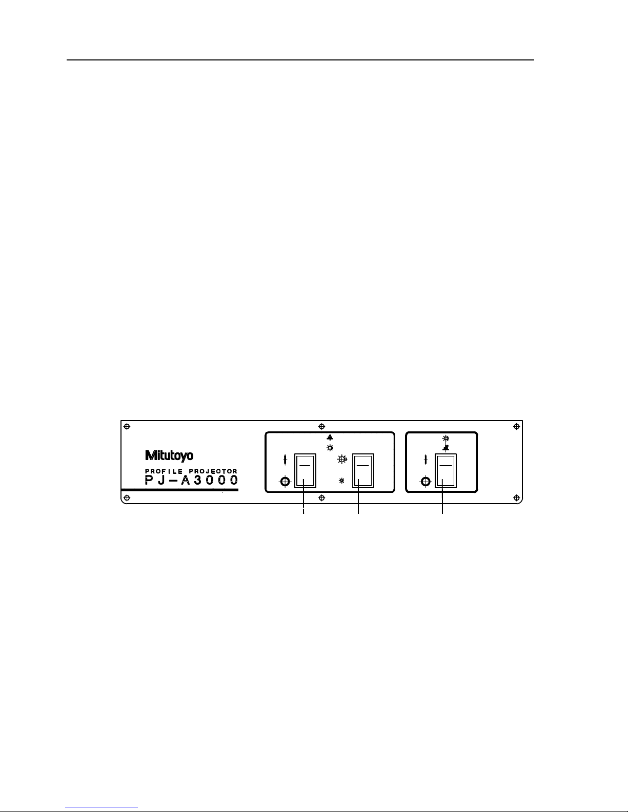
1.1.2 Control panel
[3] [2] [1]
[1] Main switch (Power switch) (|:ON / }:OFF)
[2]
Contour illumination brightness selector sw it ch
[3] Reflected illumination switch (
|:ON / }:OFF)
1 - 2 No.99MBA043A
Page 14
1. Overview
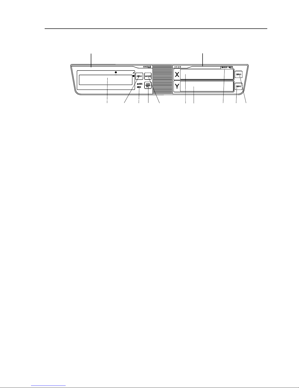
1.1.3 Angle counter and X, Y counter
(1) Angle counter (2) X, Y-axis counter
[2] [7] [8] [6]
[10]
[9] [3] [5] [4] [1]
(1) Angle counter
[1] Angle display unit
[2]
Zero-set key
[3]
ABS/INC mode indicator
[4]
Angle unit selector / offset switch
[5]
ABS/INC mode selector switch
(2) X, Y-axis counter
[6] mm/E indicator or inch/mm indicator
[7]
X-axis counter
[8]
Y-axis counter
[9]
X-axis zero-set switch
[10]
Y-axis zero-set switch
No.99MBA043A 1 - 3
Page 15
1 - 4 No.99MBA043A
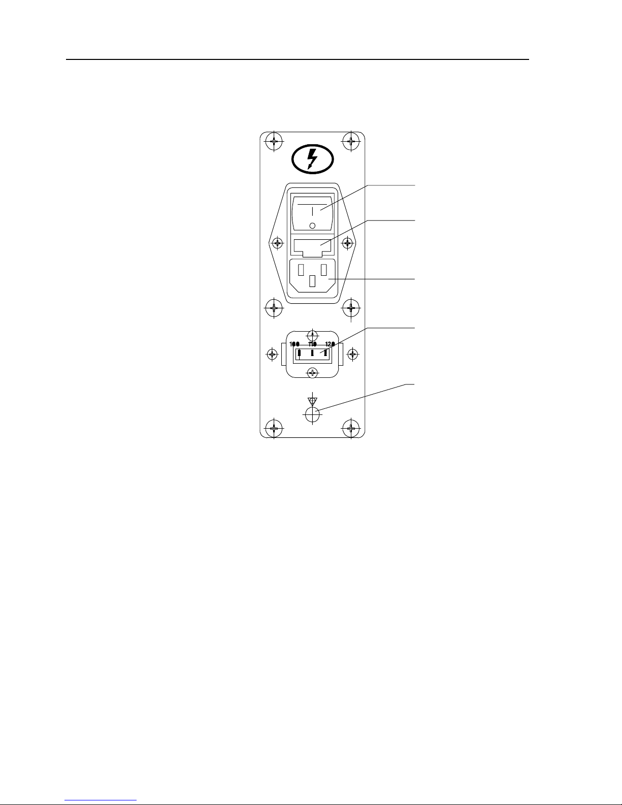
1.1.4 Power panel (Right lateral front part of main unit)
[5]
[2]
[1]
[3]
[4]
[1] Plug socket
[2]
Fuse holder
[3]
Voltage selector
[4]
GND terminal
[5]
Power switch
Page 16

Installation and Setup
This chapter describes the installation environments and connection
method of the PJ-A3000 series Measuring Projector.
2.1 Installation
2
2.1.1 Environmental Conditions
2.1.1.1 Temperature
The PJ-A3000 series Measuring Projector has been assembled and adjusted at 20°C in a
temperature controlled room. To ensure the rated measuring accuracy, the temperature at
the installation site must be maintained as close to 20°C as possible, with minimal
fluctuation. (For reference, the conditions specified by JMAS5011 are: 20°C ± 1°C with a
temperature gradient of less than 2°C per 8 hours.) In poor temperature conditions, the
accuracy performance may not be satisfied. It is illegal to make any machine adjustments
affecting the accuracy at ambient temperatures other than 20°C. After such adjustment,
accuracy is no longer guaranteed at 20°C.
2.1.1.2 Humidity
Humidity will not affect the measuring ac cur ac y directly. However, high humidity may
corrode machined surfaces and may adversely affect electronic parts. The environmental
humidity should be maintained within a range of 55% to 65%RH.
2.1.1.3 Dust and dirt
The PJ-A3000 series Measuring Projector consists of high-precision parts, including guide
faces, linear scale units, and optical unit, that must be kept free of dust and dirt. Use and
store the PJ-A3000 series Measuring Projector in a place where it w ill not be subjected to
dust and dirt.
2.1.1.4 Grounding
Connect the ground terminal with the ground terminal of grounding resistance 100 Ω or less
so that the measuring microscope may normally operate.
On the Reinstallation yyyyy The projector main unit reinstallation performed on the client's
own may deteriorate the required accuracy due to vibrations and shocks during
transportation. Therefore, it is recommended that the main unit be reinstalled by Mitutoyo. If
the system is desired to be reinstalled, be sure to contact the Mitut oyo sales office.
TIP
No.99MBA043A 2 - 1
Page 17
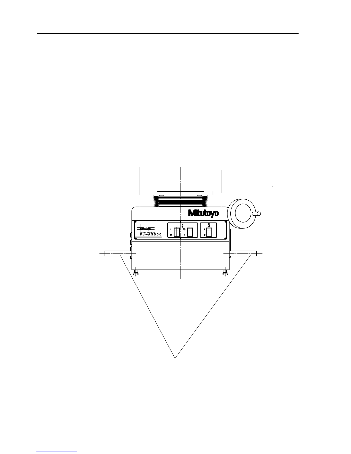
2.1.2 Transportation and installation
Be sure to use the supplied carrying handles when handling, shift ing or installing the projector
and due to its heavy weight (for PJ-A3010F-200, about 120kg) four people are required to
carry it. The PJ-A3000 series has been fully adjusted at the plant, therefore take special care
when handling and setting up the projector so that no part of the projector is subjected to
impact or vibration.
Carrying handles
2 - 2 No.99MBA043A
Page 18
2. Installation and Setup
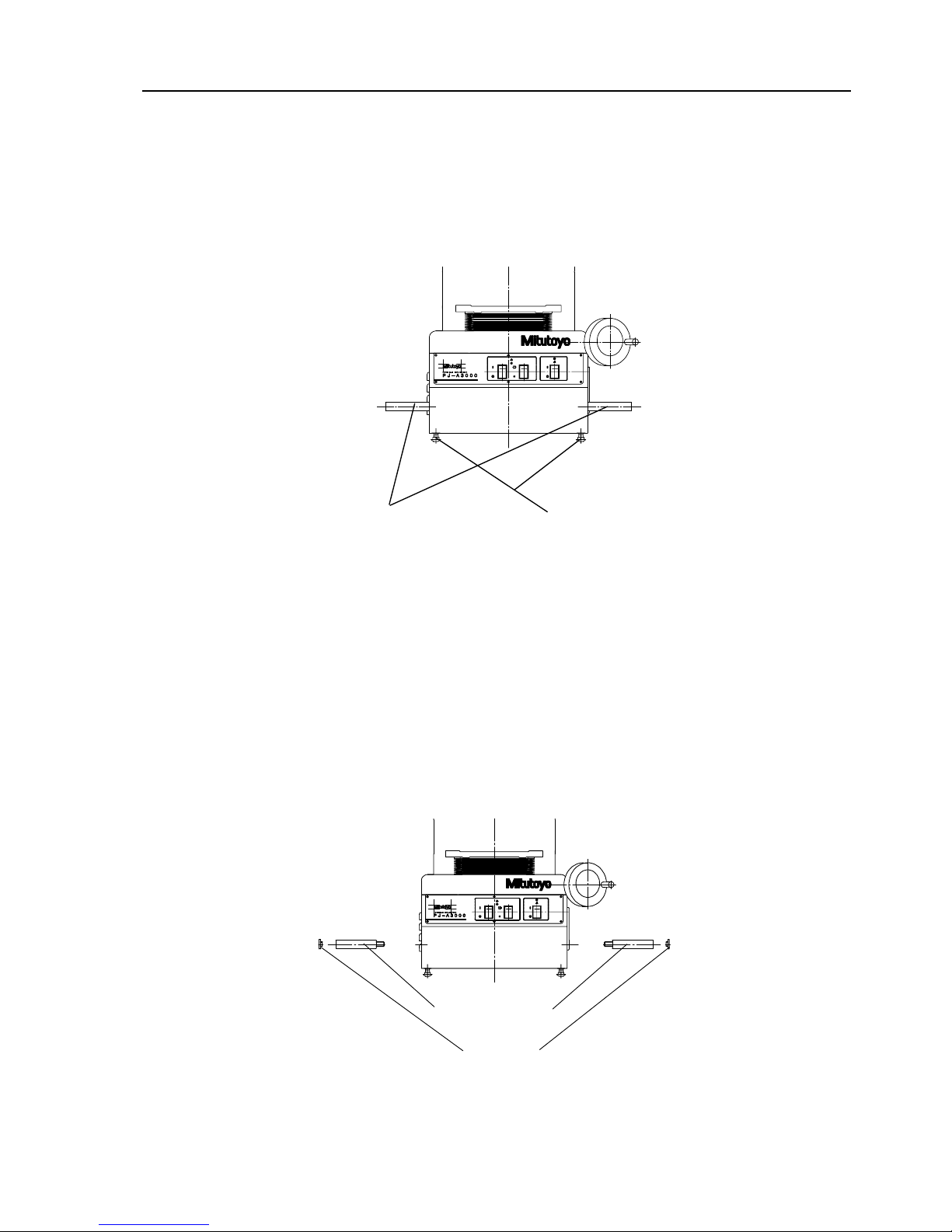
2.1.3 Setting up the main unit
The projector must be set up on the optional stand or a rigid, stable mount. Use the leveling
bolts on the projector base to compensate for any inclination.
Carrying handles
Leveling bolts
2.1.4 Removing the carrying handles
After setup, remove the carrying handles and cover the screw holes with the supplied hole
caps.
Hole caps
Carrying handles
No.99MBA043A 2 - 3
Page 19
2.2 Assembly
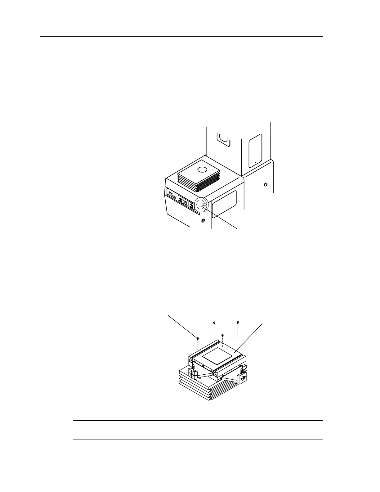
2.2.1 Installing the cross-travel stage and Digimatic Head (for PJ-A3005D-50)
1. Turn the focusing wheel clockwise to lower the cross-travel stage mount down to the
end of its displacement.
Focusing wheel
2. Gently place the cross-travel stage on the mount. Slide the moving sections to the
left and right to check the screw hole positions, then use the four hex-socket head
screws (supplied in the standard accessory box) to temporarily fix the cross-travel
stage in place.
Cross-travel stage
Hex-socket head screw
The cross-travel stage should be secured when the adjustment of its travel direction is complete.
(Refer to 2.5.2 Aligning the cross-travel stage travel direction to the cross-hair lines.)
TIP
2 - 4 No.99MBA043A
Page 20
2. Installation and Setup
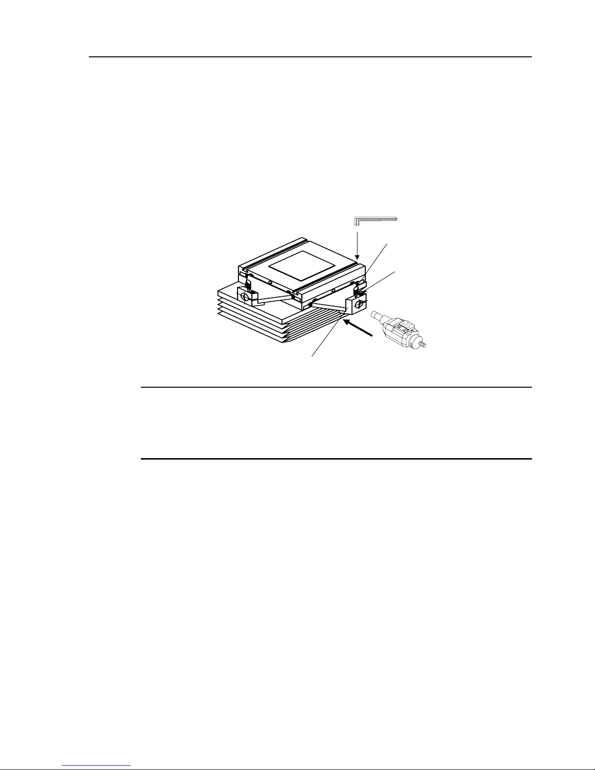
3. Installing the Digimatic Head
y Loosen the clamp screw and hex-socket head screw on the bracket.
y Slowly insert the stem of the Digimatic Head into the bracket as far as it can go, then
secure it in place with the hex-socket head screw. Do not fasten the screw too tight,
otherwise the spindle of the Digimatic Head will not move smoot hly.
Hex-socket head screw
Bracket
Clamp screw
Allen spanner
Digimatic Head
y When using a Digimatic Head or other types of heads that are not provided with a hole to clamp
the spindle, the clamp screw is not used to secure it, lightly fasten the screw.
TIP
y The Micrometer Head is provided with a hole for damping the spindle. Align this hole with the
clamp screw. If the display is not in a good viewing position, loosen the clamp screw on the
Micrometer Head sleeve, and adjust the display position.
No.99MBA043A 2 - 5
Page 21
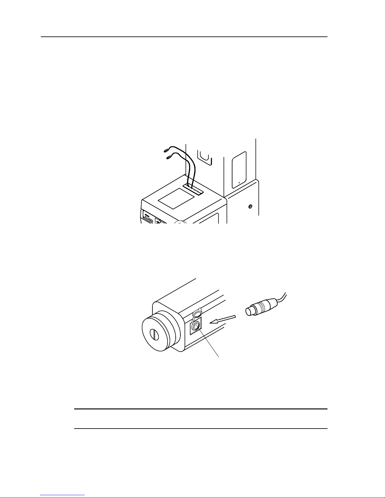
4. Connecting the Digimatic Head cables (for PJ-A3005D-50)
Remove the dust-prevention cap from the output connector on a side of the Digimatic
Head. Connect the cable for the counter to the output connector.
Output connector
Confirm sufficiently to connect so that the connection of X-axis and Y-axis may be not
wrong.
NOTE
2 - 6 No.99MBA043A
Page 22
2. Installation and Setup
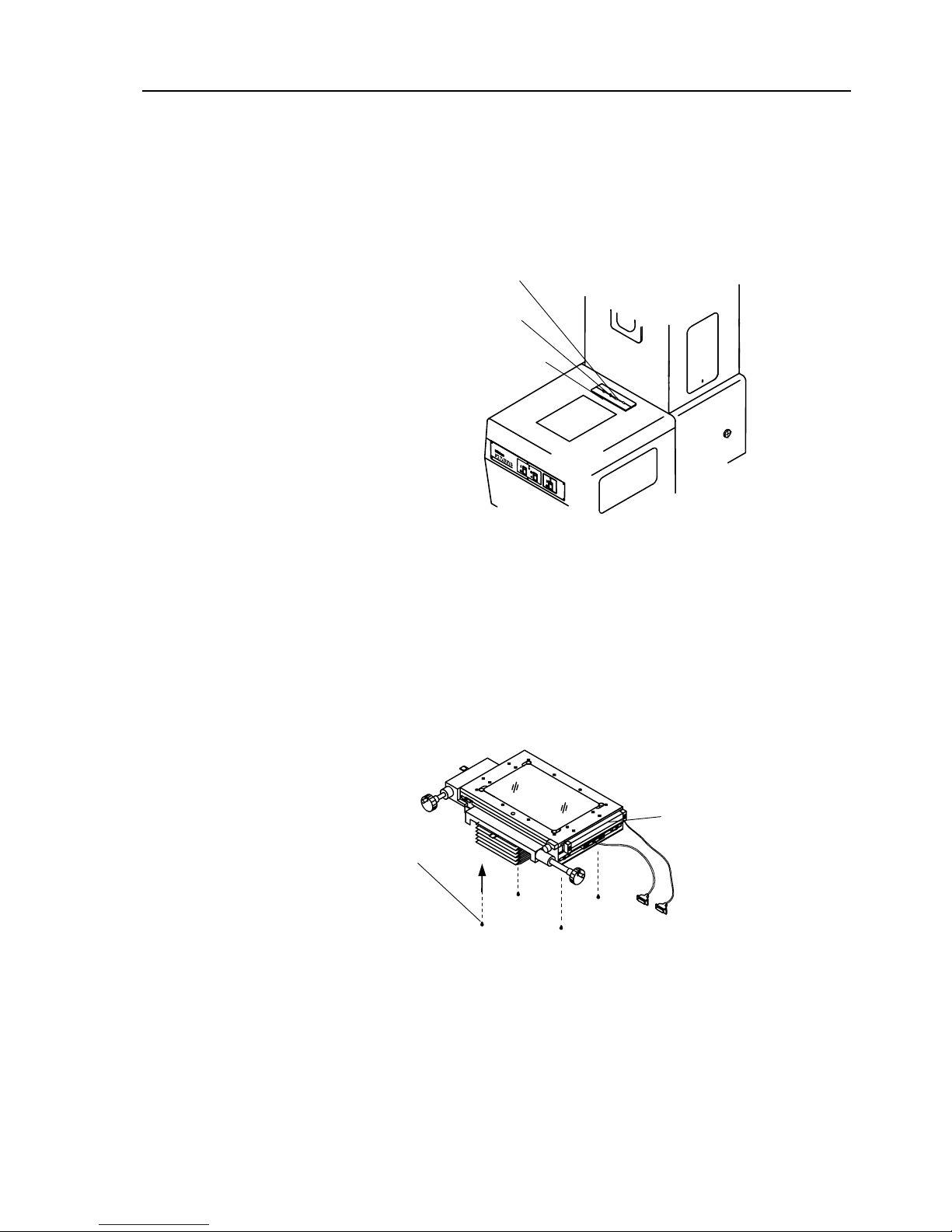
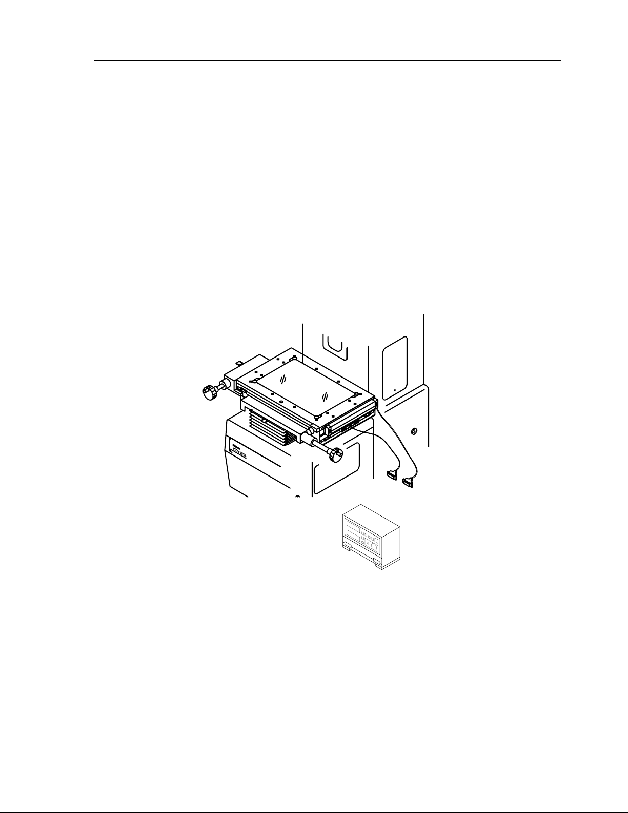
2.2.2 Installing the cross-travel stage and connecting the Linear Scale cables
(for PJ-A3010F-200)
1. Remove the cable outlet cover.
Cable outlet cover
Y-axis
X-axis
2. Gently place the cross travel stage on the cross travel stage mount. Slide the
moving parts to the left and right to align the screw holes, then use the four
hex-socket head screws supplied to temporarily fix the cross travel stage in
place.
Hex-socket
head screw
Connector for
Linear encoder
Linear encoder
3. Rotate the focusing wheel to raise the cross-travel stage as far as it will go.
No.99MBA043A 2 - 7
Page 23
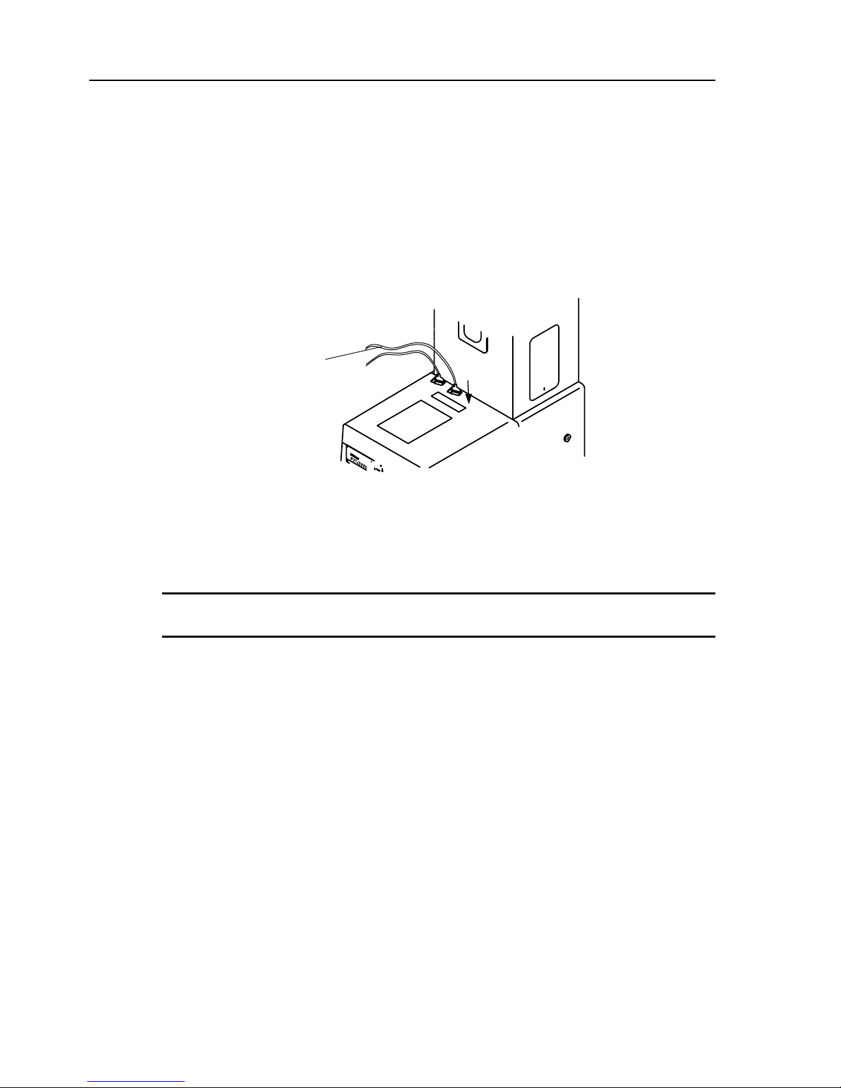
4. Place the linear encoder connector into the projector.
5.
Connect the signal cables from the circuit board in the projector to the connector.
6. Attach the cable outlet cover.
Connector for
Linear encoder
The cross-travel stage should be secured when the adjustment of its travel direction is complete.
(Refer to “2.5.2 Aligning the cross-travel stage travel direction to the cross-hair lines”.)
TIP
2 - 8 No.99MBA043A
Page 24
2. Installation and Setup
2.2.3 Connecting the Optoeye A2 Image Edge Sensor for PJ-3010F-200
1. Remove the cable outlet cover.
2. Disconnect the linear encoder connectors from the P.C.B inside the Profile Projector.
3. Attach the cable outlet cover.
4. Connect the linear encoder connectors to the Optoeye A2 Counter.
Connector for
Linear encoder
Optoeye A2 Counter
No.99MBA043A 2 - 9
Page 25
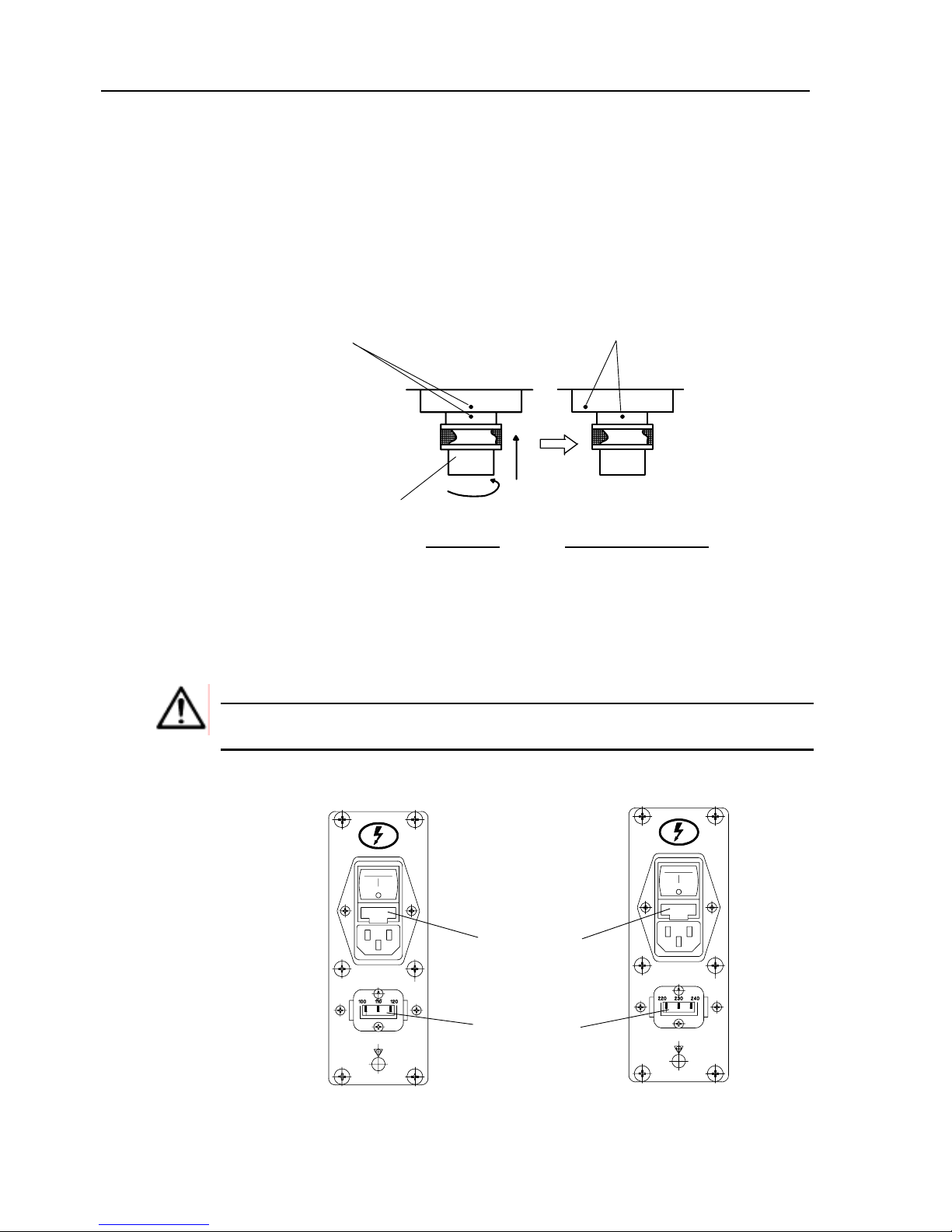
2.2.4 Mounting the projection lens
1. Remove the lens mount cap and the projection lens cap.
2. Hold the lens so that the red index dot of the projection lens faces you. Align the
index dot of the projection lens with that of the lens mount, push the projection lens
upwards, then rotate the lens clockwise approximately 60° until the lens stops.
Projection lens
Front view From right side view
Red index dot
Red index dot
2.2.5 Setting the power voltage
Set the voltage selector plug to the supply voltage as follows.
Be sure to unplug the power cord before setting the voltage selector.
Set the voltage selector at the rated voltage.
CAUTION
100 VAC-system
Fuse holder
Voltage selector
200 VAC-system
2 - 10 No.99MBA043A
Page 26
2. Installation and Setup
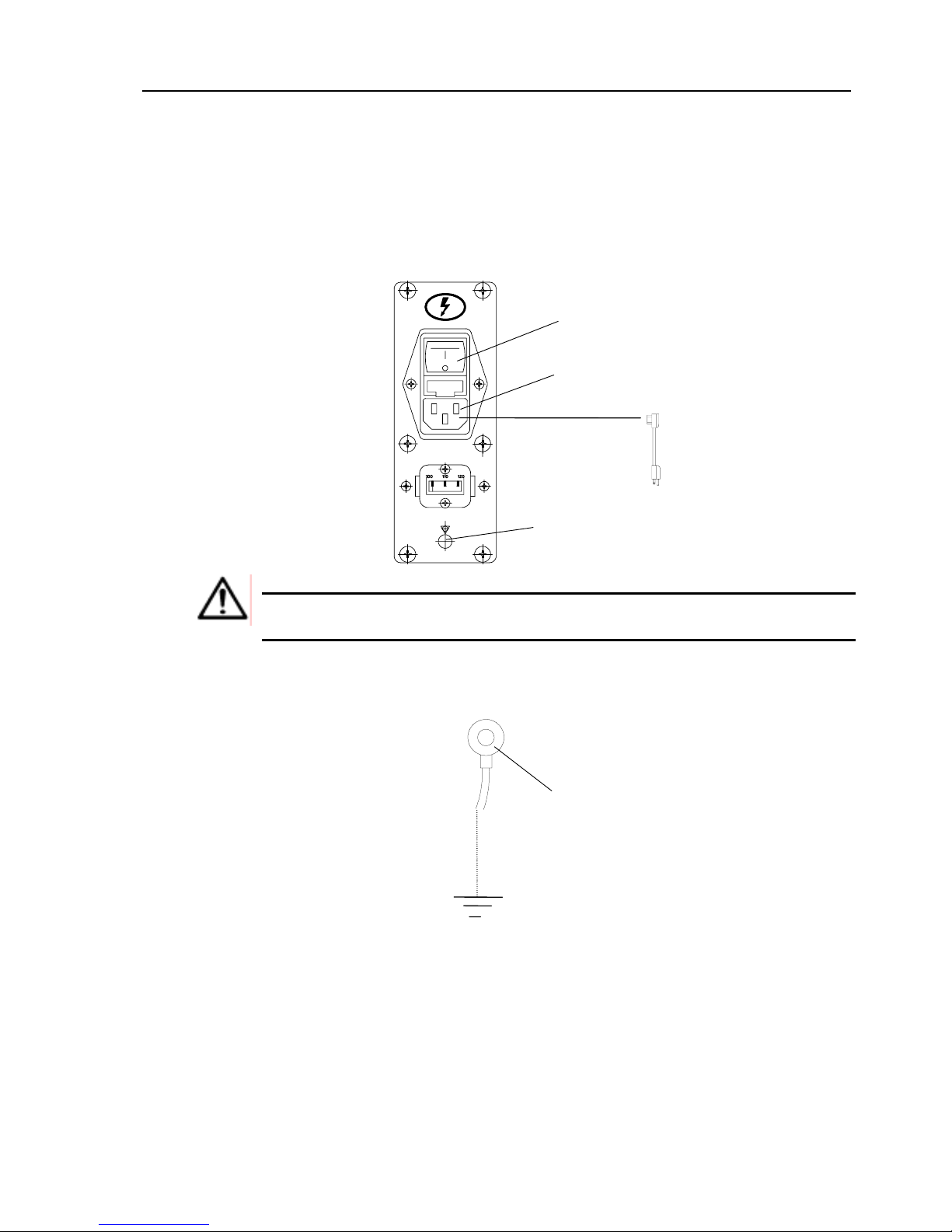
2.2.6 Connecting the power cord
1. Turn off the main switch.
2. Connect the power cord to the power panel and plug it into the power outlet.
GND
Plug socket
Main switch
Power cord
Use the power cord supplied with the projector.
Use the GND terminal for grounding.
CAUTION
GND terminal
No.99MBA043A 2 - 11
Page 27

2.3 Initial Checks (Functional Check)
Each projector is factory-inspected and adjusted, and has been safeguarded at all stages of
shipment and transport, but prior to first time use, perform the following checks.
NOTE
While checking cables, make sure that all switches are tuned OFF.
2.3.1 Electrical component connectors
Make sure that the power cord, plug socket, voltage selector, power switch, and GND
terminal are securely connected.
2.3.2 Main switch (ON-OFF)
• Does the switch operate normally?
• Does the fan motor operate?
2.3.3 Switches for Contour illumination and reflected illumination
Contour illumination switch : OFFÎON
Contour illumination brightness selector
: HIGHÎLOW
Reflected illuminator switch
: OFFÎON
• Do the switches operate normally?
• Do the illumination bulbs turn on?
• Does the brightness change normally?
2.3.4 Focusing wheel
Turn the wheel.
• Is there any play or noise?
2 - 12 No.99MBA043A
Page 28

2. Installation and Setup
2.3.5 Cross-travel stage
• Is the stage glass clean and free of scratches?
Move the stage by hand over its full range.
• Does it move smoothly?
• Is there any play or noise?
(Use the Micrometer Head to move the cross-travel stage and check the above
points.)
2.3.6 Projection screen
• Is the screen glass clean and free of scratches?
• Do the fine adjustment knob, clamp and chart clips work correctly?
2.3.7 Others
• Check the other parts of the projector and accessories for appearance and
functionality. (Refer to "5.Maintenance" in case of any malfunction.)
No.99MBA043A 2 - 13
Page 29

2.4 Initial Checks (Performance Check)
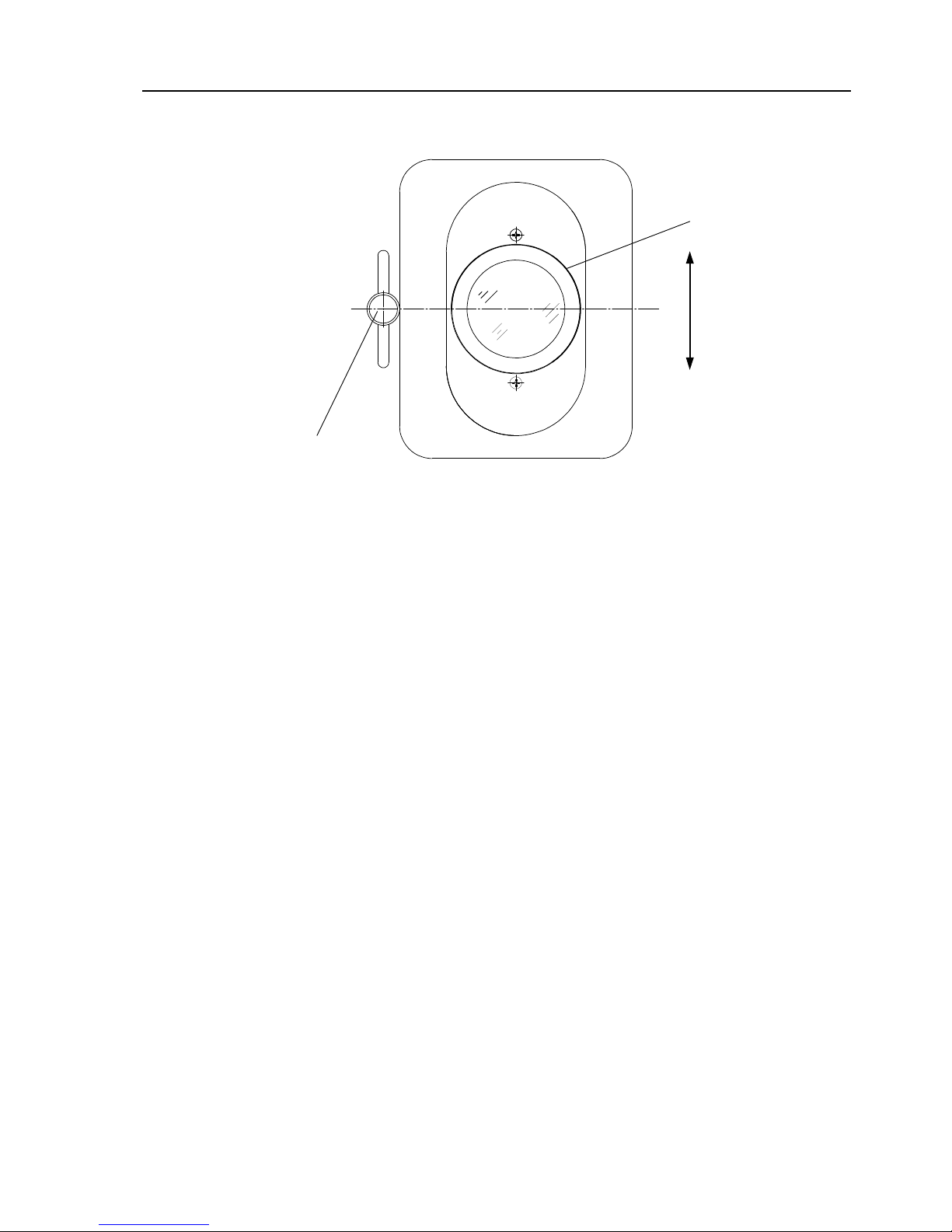
2.4.1 Checking the position of the contour illumination bulb filament
1. Carefully remove the projection lens.
2. Turn on the power switch and contour illumination switch to project the filament
of the contour illumination bulb on the screen.
3. Confirm that the filament image is projected in the approximate center of the
screen.
2.4.2 Checking the position of the surface illumination bulb filament
1. Carefully remove the projection lens.
2. Rotate the frame of the surface illuminator condenser lens clockwise until it is
fully inserted.
3. Place the half-reflecting mirror (for 10x or 20X lens) on the cross-travel stage.
Adjust the mirror position so that the light from the reflected illuminator is
reflected at right angles. Adjust t he reflected illuminator position so t hat the light
beam is directed at the center of the mirror.
4. Turn on the main switch and contour illumination switch to project the filament of
the contour illumination bulb on the screen.
5. Confirm that the filament image is proj ected in the approximate center of the
screen.
2 - 14 No.99MBA043A
Page 30
2. Installation and Setup
Clamp knob
Frame of the reflected
illumination condenser
lens
• For the vertical position adjust ment of reflected illuminator, loosen the clamp knob to adjust with t he
clamp knob or the frame of reflected illumination condenser lens.
No.99MBA043A 2 - 15
Page 31

2.4.3 Projection with contour illumination
1. Turn on the contour illuminat ion bulb.
(Use the brightness selector switch (HIGH and LOW) to select the light intensity.)
2. The workpiece profile is projected on the screen.
Projection screen
Workpiece profile
2 - 16 No.99MBA043A
Page 32

2. Installation and Setup
2.4.4 Projection with reflected illumination
1. Turn on the reflect ed illuminat ion bulb.
2. The image of the workpiece surface is projected on the screen.
3. Mount the half-reflecting mirror at the top of the projection lens frame so that the mirror
is aimed towards the surface illuminator, as shown below. Use the frame of the
reflected illumination condenser lens or the clamp knob to adjust the height of the
reflected illuminator so that the light beam is directed t o the surface of the w orkpiece.
NOTE
Refer to Note in p.2-15 for the operation of the vertical position adjustment of
reflected illuminator.
Projection lens
Half-reflecting mirror
Reflected illuminator
Projection screen
Workpiece profile
No.99MBA043A 2 - 17
Page 33

2.4.5 Color fitter
This filter reduces eye fatigue. See the following for the insertion method.
Color fitter
Main unit left side
2 - 18 No.99MBA043A
Page 34

2. Installation and Setup
2.4.6 Checking the magnification accuracy
1. Mount the projection lens. (Refer t o “2. 2. 4 Mount ing t he project ion lens”)
2. Place a standard scale (optional accessory, No. 172-116) on the cross-travel stage to
project its image on the screen.
3. Measure the projected image of the standard scale on the screen using a reading scale
(optional accessory, No. 172-161 ).
4. Take measurements at two reference points (100mm, 140mm) in four or more radial
directions along the cross-hair lines on the screen.
5. Calculate the magnification error using the following formula.
∆M =X 100 %
lM
L - lM
∆M
: magnification error
L : measured length of the standard scale
l :
length of the standard scale
M :
magnification of the projection lens
No.99MBA043A 2 - 19
Page 35

The magnification error is specified as
±0.1% or less for contour illumination, and the
tolerance for each measured point is tabulated below. (If the magnification error for
contour illumination falls within the tolerance, that for reflected illumination will also fall
within the specified tolerance of
±0.15%)
Measured point
(on the reading scale)
Tolerance Permissible range
100 mm
140 mm
±0.1 mm
±0.14 mm
99.9-100.1 mm
139.86-140.14 mm
TIP
A positive error, i.e. where ∆M is a positive value, m eans that the measured length L is
larger than the normal size (l×M), and vice versa for a negative error.
2 - 20 No.99MBA043A
Page 36

2. Installation and Setup
2.4.7 Checking the cross-travel stage travel direction
1. Mount the least magnified projection lens.
2.
Place a reference piece on the stage to project its image on the screen.
Stage glass
Reference piece
Cross-travel stage
3. Set the protractor screen reference line to "0".
“0” line
Screen rotation knob
Clamp knob
No.99MBA043A 2 - 21
Page 37

4. Move the cross-travel stage along the Y-axis (back and forth), and align the edge of the
reference piece with the horizontal cross-hair line.
5. Move the cross-travel stage along the X-axis (left and right), and confirm that the edge
of the reference piece is aligned with the horizontal cross-hair line over the entire length
of stage X-axis travel.
Projection screen
Cross-hair line
(horizontal)
Reference piece
• If a deviation from the horizontal cross-hair lines is observed, refer to 2.5 Adjustment for
remedy.
2 - 22 No.99MBA043A
Page 38

2. Installation and Setup
2.4.8 Checking the cross-travel stage feed error
If the stage moves normally in 2.4.7, checking of feed error over a 5 mm travel may be
sufficient. In this checking, many factors must be taken into consideration, including
environmental conditions and alignment error.
Any feed error should be less than 0.01 mm per 5mm of travel.
1. Mount a projection lens.
2. Place a standard scale or other reference of known size on the cross-travel stage
to project its image on the screen.
3. Feed the stage and determine the feed error by measuring the standard scale
along the X-axis (left-right) and Y-axis (front-rear).
4. Check the feed error in the opposite travel directions (i.e. returning directions) for
both X- and Y-axes.
• Contact Mitutoyo if the error is excessive.
2.4.9 Checking the resolution (in contour illumination mode)
1. Mount a projection lens.
2. Place a workpiece on the cross-travel stage and project its image on the screen.
Ensure that the image is clear over the entire screen without any obscured regions.
• Refer to 4.4.4 if an obscure region is present.
No.99MBA043A 2 - 23
Page 39

2 - 24 No.99MBA043A
2.5 Adjustment
Read this section as required after reading “2.3 Initial Checks (Function Check)” and “2.4
Initial Checks (Performance Check)”.
2.5.1 Adjusting the magnification
Magnification adjustment requires experience. When the adjustment of a projection lens
is required, contact Mitutoyo for assistance.
2.5.2 Aligning the cross-travel stage travel direction to the cross-hair lines
1. With the cross-travel stage mounting screws fastened but not tightened, carefully swivel
the stage so that the reference piece does not deviate from the horizontal cross-hair line
of the screen while feeding the stage in the X-axis direction.
Cross-travel stage
Reference piece
Sta
ge g
lass
2. When the adjustment is complete, tighten the stage mounting screws. Re-check the
stage travel direction.
Projection screen
Reference
p
iece
Cross-hair line of
the screen
2.5.3 Centering the protractor screen
• This adjustment is performed by Mitutoyo service personal.
Page 40

Operation
This chapter explains the setup for measurement including the
optical system installation and workpiece set-up.
3
3.1 Projection Lens Selection
3.1.1 Selecting the projection lens
Select the appropriate projection lens magnification according to the required field of view,
measuring method and accuracy requirements. (Refer to “6. Specifications”.)
10X 20X
50X 100X
20X
10X
Built-in
Half-reflecting
mirr
o
r
Half-reflecting mirror
Oblique mirror for rough surface
No.99MBA043A 3 - 1
Page 41
3.1.2 Replacing the projection lens
This projector has adopted the fixed focus lens to 10X to 100X.
When replacing the projection lens in order to change the magnification, it is required to
switch the condenser lens according to the magnification of projection lens.
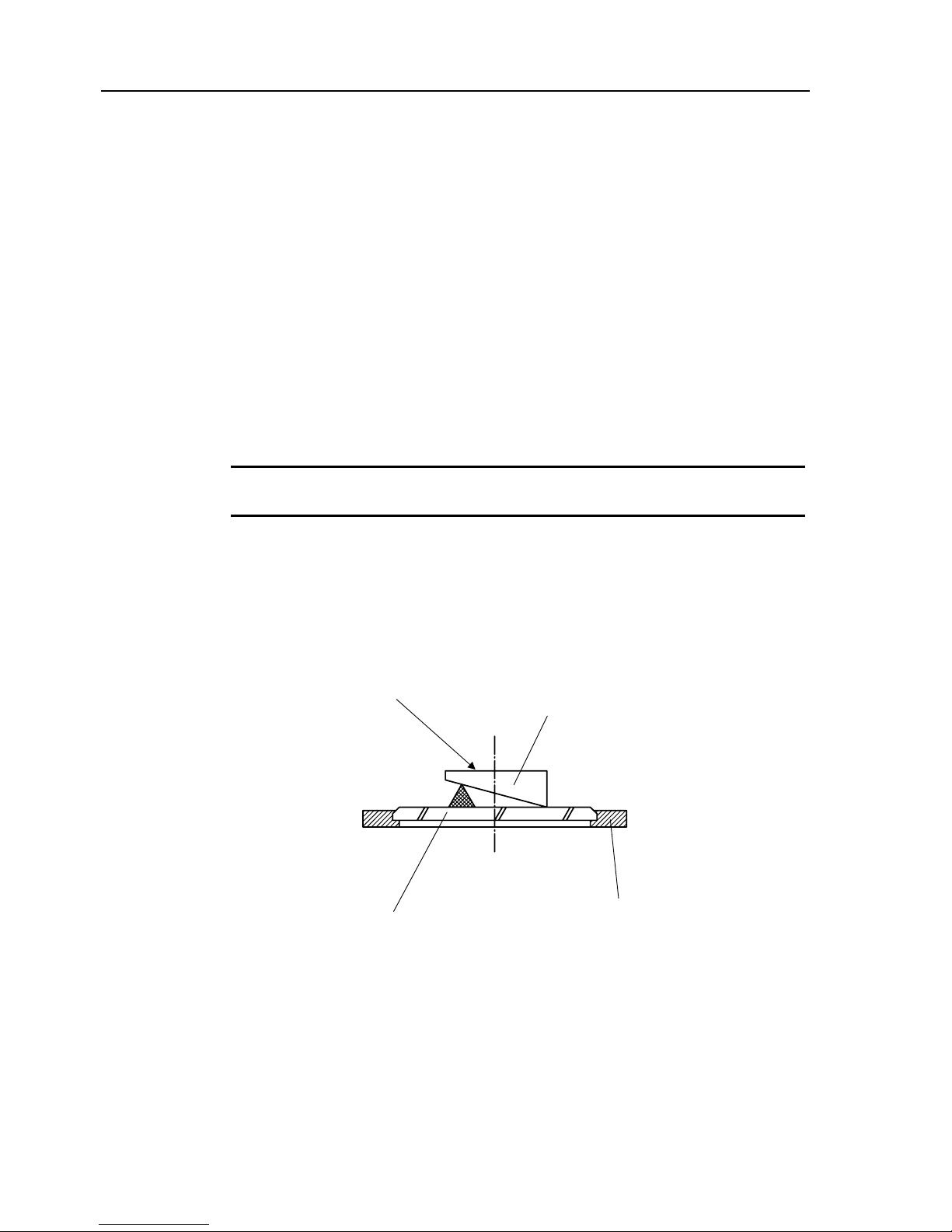
3.2 Mounting the Workpiece
Mount a workpiece on the stage glass or use a fixture or a jig to hold it in position. Use the
T-grooves for securing fixtures and jigs to the cross-travel stage.
TIP
The surface or contour to be projected must face the projection lens. Position the surface
to be measured so that it is normal to the optical axis of the projection lens.
Cross-travel stage
Workpiece
Surface to be measured
Stage glass
3 - 2 No.99MBA043A
Page 42

3. Operation
• For cylindrical workpieces : V-block and clamp (No. 172-378)
• For light-weight, flat workpieces which are difficult to fix : Clamp (No.176-107)
• For screws or cylindrical workpieces with center holes : Swivel center support
(No.176-105, No.172-197)
• Detach the stage glass, when the Swivel center support is installed. (refer to “5.3.3”)
Swivel center support
Workpiece
Stage glass
T-groove
T-groove
Cross-travel stage
Cross-travel sta
g
e
Workpiece
Clam
p
V-block and clam
p
Workpiece
Stage glass
No.99MBA043A 3 - 3
Page 43
3.3 Focusing and Positioning the Workpiece
3.3.1 Focusing
Bring the workpiece into focus by rotating the focusing wheel to move the cross-travel
stage up and down.
Projection lens
Focusing wheel
NOTE
Be careful not to bump the Projection lens against a workpiece or fixture during
focusing. Pay special attention when an stepped workpiece is mounted, or when
the workpiece is supported by a swivel center support or a V-block.
3 - 4 No.99MBA043A
Page 44

3. Operation
3.3.2 Positioning the workpiece
When the image is in focus on the screen, align the measured edge of the workpiece to
the measuring axis of the cross-travel stage. Move the workpiece or the fixture so as to
align the workpiece image with the cross-hair lines on the screen.
• Rotary table (No.176-106, 172-196) is suitable for performing alignment.
No.99MBA043A 3 - 5
Page 45

3.4 Measurement and Inspection
The measuring method for each application should be determined by the measurement
factors involved : shape, size and quantity of workpieces, purpose, required accuracy, etc.
The following methods are basic examples and can be developed further depending on
the particular requirement.
3.4.1 Rectangular coordinate measurement (with the X, Y counter)
Use the cross travel of stage to make dimensional measurements.
Align the datum point of the workpiece with a cross-hair line and take a reading off the
Micrometer Head or built-in counter. Move the cross-travel stage to align the point to be
measured to the same cross-hair line and take a reading. The difference between the two
readings is the dimension of the workpiece (or the distance between the two points).
Dimension
3 - 6 No.99MBA043A
Page 46

3. Operation
• Operation
Operation When using the X, Y counter (PJ-A3005D,
PJ-A3005F, PJ-3010F)
Move the stage so that one
end of the workpiece is
aligned with the cross-hair.
Press the zero button of
the X-axis to set the
counter to zero.
Move the stage so as to
align the other end of the
workpiece with the
cross-hair.
Take a reading from the
counter.
Zero setting
Dimension is displayed
NOTE
The following procedure must be performed on the PJ-A3005D-50:
Set the Digimaldc Head to zero when the counter has been zeroed. Otherwise, the
displayed values on the counter and Digimatic Head will not be the same.
No.99MBA043A 3 - 7
Page 47

• X, Y-axis counter (PJ-A3005D-50, PJ-A3010F-100, PJ-A3005F-150, PJ-A3010F-200)
1
mm/E indicator or inch/mm indicat or The LED for the active unit is lit.
PJ-A3005D
PJ-A3005F
2 X-axis counter Resolution
PJ-A3010F
0.001 mm
PJ-A3005D 0.001 mm
PJ-A3005F 0.001 mm
3 Y-axis counter Resolution
PJ-A3010F 0.001 mm
4 X-axis zero-set switch
Sets the X-axis counter to zero at any X- axis
position of the stage.
5 Y-axis zero-set switch
Sets the Y-axis counter to zero at any Y-axis
position of the stage.
[1]
X, Y-axis counter
[4]
[5]
[2]
[3]
TIP
A value in units of E is displayed by dividing a displacement in units of mm by 25.4.
3 - 8 No.99MBA043A
Page 48

3. Operation
3.4.2 About parameters
To actually perform measurement, it is necessary to set up the count direction (count-up or
count-down direction), resolution, etc. Also, if setting compensation constant s for measuring errors
generated according to mechanical operation and various conditions, you can make a
measurement more easily and correctly. These conditions and constants are referred to as
parameters. This subsection describes the function and setting procedure of each parameter.
(1) Function
Some parameters are effective for all axes and other parameters are necessary to be set for each
axis. All axes
is described for the parameters that are effective for all axes and Individual axis
is described for the parameters to be set for each axis, respectively, in the Setting column of the
following table.
No. Parameter function Setting
F1
Display unit [mm/E (inch)] setup
All axes
Each time the Q-axis zero-set button on the
counter is pressed, the count unit display
LED [mm] or [E] is selected (lit) alternately.
F2.1
Count direction of X-axis(count-up or
count-down direction) setup
F2.2
Count direction of Y-axis(count-up or
count-down direction) setup
Individual axis
Each time the Q-axis zero-set button on the
counter is pressed, the display of [UP] or
[dn] is selected (displayed) alternately and
the count direction is switched.
F4.1
Linear error correction value setup for
X-axis
F4.2
Linear error correction value setup for
Y-axis
Individual axis
0 :No correction
20 :Correction value of 20mm/m
40 :Correction value of 40mm/m
80 :Correction value of 80mm/m
160 :Correction value of 160mm/m
320 :Correction value of 320mm/m
-20 :Correction value of -20mm/m
-40 :Correction value of -40mm/m
-80 :Correction value of -80mm/m
-160 :Correction value of -160mm/m
-320 :Correction value of -320mm/m
For the projectors of the type using Digimatic Head, pay attention to next points.
1.
Be sure to use after the setup of No. F1 par amete r ( s etup of the display unit ) and Digimatic
Head are agreed.
NOTE
2.
It is not possible to reverse the counting direction by the counter, because No. F2.1 and F2.2
parameter ( setup of the count direction ) are invalid.
3.
Use as correction quantity set value "0", because No. F4.1 and F4.2 parameters ( linear error
correction ) are invalid.
No.99MBA043A 3 - 9
Page 49

No. Parameter function Setting
F5
Setup for the number of smoothing
times
(Smoothing : Function to suppress
flickering of the least significant digit by
averaging detected values for several
times of sampling, if these LED display
values are difficult to read due to
flickering caused by vibration, etc., of
the installation site.)
All axes
1 : One time of sampling
8 : 8 times of sampling
16 : 16 times of sampling
32 : 32 times of sampling
F7.1
RS-232C communication condition
setup
[Baud rate]
1200 bPS : 1200 bps
2400 bPS : 2400 bps
4800 bPS : 4800 bps
9600 bPS : 9600 bps
19200 bPS : 19200 bps
F7.2
RS-232C communication condition
setup
[Data length]
7 b : 7 bits
8 b : 8 bits
F7.3
RS-232C communication condition
setup
[Parity]
non : None
En : Even
odd : Odd
F7.4
RS-232C communication condition
setup
[Stop bit]
1 b : 1 bit
2 b : 2 bits
F7.5
RS-232C communication condition
setup
[Flow control (Xon/Xoff)]
on : (Xon/Xoff) enabled
OFF : (Xon/Xoff) disabled
F8
Setup for the number of output axes
(Sets the serial output to either two-axis
of X and Y or three-axis of X, Y, and Q)
2AS : X,Y-axis
3AS : X,Y,Q-axis
F9
RS-232C output format setup
(Sets RS-232C data to the output format
of Mitutoyo data processing unit
MPK-9/7/5)
1 : MPK-9/7/5 specification
2 : Special use
For the projectors of the type using Digimatic Head, pay attention to next points.
NOTE
Use as one time of sampling, because No. F5 parameter ( setup for the number of
smoothing times ) is invalid.
1.
Use the setting "1" at No. F9 parameter. The setting "2" is the special use.
NOTE
2. No. F10 to F13 parameters are the special use.
Don't modify the setting (the initial value is "1" for F10, "2" for F11, "1" for F12, and "1"
for F13).
3 - 10 No.99MBA043A
Page 50

3. Operation
(2) Parameter setting procedure
Q-axis
Y-axis display unit
X-axis displa y unit
Parameter
setup
example
Button
operation
Q-axis display Operating procedure
cStarting the
parameter
setup mode
MODE
+
ABS/INC
Hold down the “MODE” and
“ABS/INC” buttons at a time
more than 3 seconds.
dSwitching
parameters
MODE
F1 → F2.1 → ∙∙∙
F8 → F9 → ∙∙∙
Each time the “MODE” button is
pressed, the parameter display
changes to the next in
incremental order. The
parameters are looped.
eSwitching
parameter
settings
ZERO
0.1 → 0.5 → 1.0 → 0.1 ∙∙∙
(For a resolution)
Each time the Q-axis zero-set
button is pressed, the parameter
setting changes to the next. The
parameter settings are looped.
fExiting the
parameter
setup mode
(Loading the
set content)
MODE
+
ABS/INC
Hold down the “MODE” and
“ABS/INC” buttons at a time
more than 3 seconds.
NOTE
The set content is not memorized in the counter , if tur ning the power switch of
projector off without performing the operation of f. Be sure to perform the
operation of
f when setting the parameter.
(3)
Correction of the angle counter
Correct the angle counter in order to perform the accurate measurement, before it is used for the
first time.
1.Turn the power switch ON, while the “ABS/INC” button of angle counter is pressed.
2. Adjust the intersection point with the cross hairs of screen glass and index to continue
pressing the angle display zero-set key for about three seconds. (I t is possible to perform the
zero-set at the condition of ABS mode.)
No.99MBA043A 3 - 11
Page 51

3.Rotate the screen glass so that the rotation knob and the display of angle counter is counted
in the plus direction. Revolve the screen glass to adjust the cross hairs of screen glass with
the index once again.
4.The angle counter is corrected, when the display unit switching key and the angle display
zero-set key are pressed in the condition of step 3 simultaneously. (The display is 360
°00’ or
360.00
°.)
• The correction value after the correction is preserved even if the power switch is turned OFF.
• The correction is not possible, when the screen glass is rotated in the negative direction.
3 - 12 No.99MBA043A
Page 52

3. Operation
Parameter
setup
example
Button
operation
Counter display Operating procedure
Setting the
display unit
(Selecting mm)
MODE
ZERO
1.Press the “MODE” button to
select parameter [F1].
2.Press the “ZERO” button to
select [mm].
Setting the
count direction
(Reversing the
count direction
of X-axis)
MODE
ZERO
1.Press the “MODE” button to
select parameter [F2.1].
2.Press the “ZERO” button to
select the setting (here [dn])
unlike present setting (here
[UP]).
Setting the
count direction
(Reversing the
count direction
of Y-axis)
MODE
ZERO
1.Press the “MODE” button to
select parameter [F2.2].
2.Press the “ZERO” button to
select the setting (here [UP])
unlike present setting (here
[dn]).
Setting the
linear error
correction
value(Selecti ng
the X-axis
correction value
of 40mm/m)
MODE
ZERO
1.Press the “MODE” button to
select parameter [F4.1].
2.Press the “ZERO” button to
select [40].
Setting the
linear error
correction
value(Selecti ng
the Y-axis
correction value
of 20mm/m)
MODE
ZERO
1.Press the “MODE” button to
select parameter [F4.2].
2.Press the “ZERO” button to
select [20].
Setting the
number of
smoothing
times(Selecting
8 times of
smoothing)
MODE
ZERO
1.Press the “MODE” button to
select parameter [F5].
2.Press the “ZERO” button to
select [8].
No.99MBA043A 3 - 13
Page 53

Parameter
setup
example
Button
operation
Counter display Operating procedure
Setting the
RS-232C
communication
condition(Selectin
g a baud rate of
9600bps)
MODE
ZERO
1.Press the “MODE” button to
select parameter [F7.1].
2.Press the “ZERO” button to
select [96].
Setting the
RS-232C
communication
condition(Selecti
ng a data length
of 7 bits)
MODE
ZERO
1.Press the “MODE” button to
select parameter [F7.2].
2.Press the “ZERO” button to
select [7b].
Setting the
RS-232C
communication
condition(Selecti
ng the even
parity)
MODE
ZERO
1.Press the “MODE” button to
select parameter [F7.3].
2.Press the “ZERO” button to
select [En].
Setting the
RS-232C
communication
condition(Selecti
ng one stop bit)
MODE
ZERO
1.Press the “MODE” button to
select parameter [F7.4].
2.Press the “ZERO” button to
select [1b].
Setting the
RS-232C
communication
condition(Selecti
ng the flow
control of
enabled
Xon/Xoff)
MODE
ZERO
1.Press the “MODE” button to
select parameter [F7.5].
2.Press the “ZERO” button to
select [on].
Setting the
number of
output
axes(Selecting
3 axes)
MODE
ZERO
1.Press the “MODE” button to
select parameter [F8].
2.Press the “ZERO” button to
select [3AS].
3 - 14 No.99MBA043A
Page 54

3. Operation
3.4.3 Dimensional measurement using a scale
Place the scale on the screen and measure the enlarged image.
Divide the measurements by the magnification of the projection lens to determine the
actual dimensions.
[Example]
Measured value on the screen: 150mm
Projection lens magnification: 10X
150/10=15
Actual dimension of the workpiece: 15mm
Work
p
iece
Projection screen
Scale
Magnified
dimension
y The optional reading scale is ideal for this type of measurement because the graduated
surface of the scale fits on the screen glass, providing parallax-free measurement.
3.4.4 Comparison with an overlay chart
Measurement and inspection are performed by comparing the workpiece image with the
standard overlay chart which is custom-made for the selected magnification. Use this
method for measurement of shapes, multiple points and dimensions.
This method of measurement is suitable for checking a compl icated part feature which
cannot be inspected in a simple one-dimensional measurement.
Adding tolerance lines onto the standard overlay chart will improve inspection efficiency,
since workpieces can be inspected with reference to these lines.
Standard charts can be made from the workpiece blue print, or the master workpi ece
image projected on the screen. Use transparent or semi-transparent tracing sheets(or
film) to make them. For close inspecti on or for long-term storage, plastic tracing sheets
are recommended because of their greater dimensional stability.
Tolerance lines
No.99MBA043A 3 - 15
Page 55

3.4.5 Angle measurement (Using the Angle counter)
Using the protractor screen and the rotary table for measuring angles:
• Loosen the clamp knob and use the rotation knob to turn the protractor screen.
Screen rotation knob
0” line
Clamp knob
NOTE
Always use the rotation knob to rotate the protractor screen. Other methods of
screen rotation may cause an error in angle measurement.
• Angle counter
The angle counter has two measurement modes : ABS mode for absolute measurement
and INC mode for comparative measurement. Use the [ABS/INC] key to select the mode.
Pressing the [ZERO] key sets the counter to zero at any angular position.
At power on, the counter is in ABS mode with 0 being displayed. Holding down the
[MODE] key for about 2 seconds can toggle the smallest unit of the angle counter
between 0.0
° and 1'.
Each time the [MODE] key is pressed, the display of smallest unit is switched.
3 - 16 No.99MBA043A
Page 56

3. Operation
[4][5][3][2][1]
Angle counter
[1] Angle display
Range : ±360° (±370° in ABS mode)
Resolution : 1' (or 0.01
° )
[2]
Zero-set key
Sets the angle counter to zero at any position desired.
ABC mode : Hold down the key for about 3 seconds.
INC mode : Press then release the key.
[3]
ABS/INC mode indicator
The LED for the active mode is lit.
[4]
Angle unit selector/offset switch
Unit of angle display : Switches the smallest unit of the angle counter between 0.01°
and 1'(Default is 1' at power on). For this switching hold down the switch for about 2
seconds.
Offset function : Enables an easy angle measurement. Each time the switch is
pressed the displayed angle increments by 90
°.
[5]
ABS/INC mode selector switch
Switches between ABS and INC modes. (Default is ABS mode at power ON.)
• INC mode
Use the INC mode to perform comparative measurement. Pressing the [ABS/INC] key
when in ABS mode switches to INC mode and the counter is Set to Zero.
Press the [ABS/INC] key again to return to ABS mode where the current screen angle
from the datum is displayed.
• Error codes
E-oF :
Counter overflow
E-oS :
Overspeed error
If one of the above errors are displayed, press the [ZERO] key to clear the error. Then
set the datum edge again in ABS mode.
No.99MBA043A 3 - 17
Page 57

• Measuring in ABS mode
(Angle counter setting : 1')
Step Procedure Screen Counter Display
1
Align the vertrex of the angle
to be measured with the
intersection of the cross-hair
lines, then rotate the
protractor screen to align
one edge of the angle with a
cross-hair line. Set the angle
counter to ABS mode and
establish a datum on the
edge by setting the counter
to Zero.
2
Rotate the protractor screen
to align the other edge of the
angle with the same
cross-hair line used in (1).
The measured angle is
displayed on the angle
counter.
1
It is also possible to measure
angles by using stage cross
travel to align the edges with
the cross-hair lines. Align on
edge of the angle with a
cross-hair line. Set the angle
counter to ABS mode and
establish a datum on the
edge by setting the counter
to zero.
2 Feed the stage in the X-axis
direction as shown on the
left.
3
Rotate the protractor screen
to align the other edge of the
angle with the same
cross-hair line used in (1).
The measured angle is
displayed on the angle
counter.
3 sec.
3 sec.
3 - 18 No.99MBA043A
Page 58

3. Operation
• Measuring in ABS/INC mode
(Angle counter setting : 1')
Step Procedure Screen Counter Display
1
Align a cross-hair line on the
screen with the datum. Set
the angle counter to ABS to
mode, then set it to zero.
2
Rotate the protractor screen to
measure angle
θ
A
(=θ1).
3
Switch to INC mode to set
the counter to zero.
4
Rotate the protractor screen
to measure angle
θ
B
.
5
Measure θ2.
(
θ
2
is displayed when
switching to the ABS mode.
)
6
Switch to INC mode to set
the counter to zero.
3 sec.
No.99MBA043A 3 - 19
Page 59

Step Procedure Screen Counter Display
7 Rotate the protractor screen to
measure
θc.
8 Measure θ
3
.
(
θ
3
is displayed when switching
to the ABS mode.
)
3 - 20 No.99MBA043A
Page 60

3. Operation
(2) Using the protractor screen and the rotary table for measuring angles:
The cross travel of the stage is normally used in conjunction with the rotary movement of
the table for measuring angles, because it is difficult to align the center of the rotary table
with the vertex of the measured angle.
Align one of the screen cross-hair lines with an edge of the angle to be measured and
read the angle. Rotate the table to align the other edge with the hair line and read its
angle. the difference between the two readings represents the angle of the workpiece
edge. It is not necessary for the angle vertex to remain positioned in the center for
angular measurement, only that the edges be correctly aligned with the cross hair when
readings are taken.
The rotary table No.172-196 can be read in 2' and No.176-106 in 6' increments (using
the vernier scale).
No.172-196 No.176-106
Diameter of the stage top φ 146 mm φ 112 mm
Effective diameter of the stage glass φ 97 mm φ 60 mm
Vernier scale
No.99MBA043A 3 - 21
Page 61

3 - 22 No.99MBA043A
MEMO
Page 62

Troubleshooting
4
4.1 Main Unit
Symptom Check point Remedy
1)
The fan motor
does not operate,
even if the power
switch is on.
1)Is the power cord securely
connected?
2)
Is the power supply voltage
consistent with the rated voltage?
3)
Is the fuse OK? (not blown)
1)
Connect the power cord
securely.
2)
Adjust the power supply
voltage to the rated voltage.
3)
Replace the fuse.
2)
The transmitted
illumination
halogen bulb dose
not light up
1)Is the pilot lamp on?
2)Is the cable for the transmitted
illuminator properly connected.
3)Is the illumination halogen bulb OK?
1) Refer to the symptom1.
2) Connect the cable properly.
3)Replace the halogen bulb.
3)
The vertical
reflected
illumination
halogen bulb dose
not light up.
1)Is the pilot lamp on?
2)Is the cable for the vertical reflected
illuminator properly connected.
3)Is the illumination halogen bulb OK?
1) Refer to the symptom1.
2) Connect the cable properly.
3)Replace the halogen bulb.
4)
The image is
unclear.
1)Check if the lens and workpiece are
stained.
2)Check if the light intensity of the
illumination is improper.
3)Check if the lens is loosened.
4)Check the environments for
vibration and electric noise.
1) Clean the lens and workpiece.
2)Adjust the light intensity.
3)Tighten the lens.
4)Optimize the environmental
conditions.
5)
Abnormal sound
and vibration are
generated.
1)Check if the legs on the main
unit/installation stand are loose.
2)Check if the main unit/installation
stand is not level.
1)Tighten the legs on the main
unit/installation stand correctly.
2)Perform leveling of the main
unit/installation stand.
6)
The measurement
data will not be
steady.
1)Check if the stage glass is fixed.
2)Check if the lens is loosened.
3)Check if the workpiece is fixed
properly.
4)Check if the lens and
glass are
contaminated.
5)Check if the environmental
conditions such as the temperature
and vibration are within the
tolerance range.
1)Fix the stage glass
2)Tighten the lens.
3) Fix the workpiece properly.
4) Clean the lens and
glass.
5)Optimize the environmental
conditions.
No.99MBA043A 4 - 1
Page 63
4.2 Counter Unit
Symptom Check point Remedy
1)
Nothing is
displayed when
the power switch
is on.
1) Is the power cord securely
connected?
2) Turn the power switch off, then turn
it on after at least five seconds.
1) Connect the power cord
securely.
2) Try a few times. If the light still
dose not come on, contact
Mitutoyo.
2)
Counter display is
locked (no
counting.)
1) Turn the power switch off, then turn
it on after at least 5 seconds.
2) Check the following.
(Example) If the X-axis counter
operates correctly and the Y-axis
counter dose not, swap the X-and
Y-axis Linear Scale connections.
•
•
If the same problem persists on the
same counter (i.e. X-axis counter
operates correctly, Y-axis counter
does not operate correctly),the
counter is damaged.
If the problem occurs on the other
counter (i.e. X-axis counter does
not operate correctly, Y-axis
counter operates correctly),the
Y-axis Linear Scale is damaged.
1) Try a few times. If the counter
display is still locked, go to
check point.
2) If the counter or any Linear
Scale is found to be damaged,
contact your dealer or the
nearest Mitutoyo sales office.
3) Miscounting
1)Is the wire from the main unit GND
terminal grounded securely?
2)Is there any noise source nearby?
3)See “Counter display is locked”
category in Malfunction column.
1)Securely ground the wire from
the main unit GND terminal.
2)The counter should be
separated by at least 0.5m from
high-voltage or large-current
sources and high-capacity
relays.
3)If the counter or any Linear
Scale is found to be damaged,
contact your dealer or the
nearest Mitutoyo sales office.
4)
Count value
fluctuates
1)Are vibrations affecting the Linear
Scales?
1)Take countermeasures to
minimize the effects of the
vibration.
5)
Errors of "E20"
and "F30" are
displayed.
1)
Refer to “4.3 Error Messages and Remedies”.
6)
Errors of "E51"
and "E52" and
"E53" are
displayed.
1)
Refer to “4.3 Error Messages and
Remedies”.
2)
Have the power switches been
turned on or off according to the
right column?
1)
Refer to “4.3 Error Messages
and Remedies”.
2)
Turn the power switches on or
off in the following order.
For ON Peripheral equipment →
Projector main unit
For OFF Projector main unit →
Peripheral equipment
If any other trouble than those listed above is encountered, contact your dealer or the nearest
Mitutoyo service center.
4 - 2 No.99MBA043A
Page 64

4. Troubleshooting
4.3 Error Messages and Remedies
LED display
Meaning and remedy
Overspeed arising ; Traverse speed of the axis which displayed the error is so fast.
xxxPress the zero-set button of the axis which displayed the error or restart t he
microscope main unit.
Overcount arising ; The scale of the axis which displayed the error exceeds the
possible counting range.
xxx
Return the scale of the axis which displayed the error to the possible counting
range or restart the microscope main unit.
RS232C parity error
xxx
Press the X-axis zero-set button. Restart bot h of the equipment connected with the
counter at RS232C and the microscope main unit, when the communication is not
resumed.
RS232C over-run error
xxx
Press the X-axis zero-set button. Restart bot h of the equipment connected with the
counter at RS232C and the microscope main unit, when the communication is not
resumed.
RS232C framing error
xxx
Press the X-axis zero-set button. Restart bot h of the equipment connected with the
counter at RS232C and the microscope main unit, when the communication is not
resumed.
When an error code has been cleared (power is turned on), the counter displays all zeros. Perform
measurement from the start.
TIP
If there is play or abnormal noise present, contact Mit utoyo. Do not disassemble the unit or unit
or force the wheel.
4.4 Others
4.4.1 Error is observed in glass scale or overlay chart measurement.
This may be a magnification error. Check the magnification accuracy by referring to 2.4.6.
Contact Mitutoyo if adjustment or repair is required.
4.4.2 Abnormal cross-travel stage operation, and measurement errors occur.
Check the cross-travel stage operation by referring to 2.4.7 and 2.4.8. Contact Mitutoyo if
adjustment or repair is required.
No.99MBA043A 4 - 3
Page 65

4 - 4 No.99MBA043A
4.4.3 Abnormal protractor screen operation.
If the screen rotation, fine adjustment, or clamp dose not work normally, contact Mitutoyo. Do
not force them.
4.4.4 Partial obscured image.
Check the following points. Contact Mitutoyo when required depending on the problem:
(1)
Is the projection lens properly mounted?
(2)
Focusing
(3) Oil stains on the workpiece or stage glass
(4) Stains or damage to the projection lens
(5) Stains or damage to the surface reflecting mirror
4.4.5 Digimatic Head Key Operation and Counter Display
(for PJ-A3005D-50)
Digimatic Head Counter
Press the [+/-] key. The sign changes.
Press the [RESET] key.
Start of presetting (“P” blinks).
“E81” is displayed.
Press the
[ZERO/ABS] key
c ZERO
d ABS
c “0.000” is displayed.
d The value displayed on the
Digimatic Head is displayed.
Press the
[ON/OF] key
c OFF
d ABS
c “E81” is displayed.
d “0.000” is displayed.
Page 66

Maintenance
This chapter explains the daily maintenance that must be performed
on the Measuring Projector PJ-A3000 series, including cleaning and
the replacement of consumable parts.
5
5.1 Maintenance of Optical Components
5.1.1 Projection lens
Compared with ordinary hard glass, the optical glass of the projection lens used for the
projector is soft and subject to scratches. In order to remove dust do not use a cloth to
wipe the lens, but use a blower brush instead.
To remove oil or fingerprints, dampen clean gauze with a mixture of high-grade alcohol
and ether in a ratio of 8 to 2, and wipe gently using a circular motion.
For lens storage, replace the lens cap and store it in its case.
Also replace the lens cap when the projector is not in use, although the lens does not
have to be removed from the projector.
5.1.2 Half-reflecting mirror for surface illuminator
The half mirror for 10x and 20X is coated with a plastic film which tends to collect dust.
Since the mirror surface is subject to scratches, take sufficient care when handling it.
Use a blower brush to remove any dust from the mirror.
5.1.3 Mirror (surface reflecting mirror)
Since the mirror used in the projector is silvered on its front face rather t han on its back,
unlike ordinary mirrors, it is highly subject to scratches. Ensure it is free from dust or oil.
Should the mirror become stained, use the same cleaning procedure as for the
projection lens. Greater precautions, however, are required for handling the mirror.
5.1.4 Screen glass
Use a soft cloth with diluted neut ral detergent and wipe the glass w hen removing oil and
finger print. After wiping, remove the detergent by wiping with a soft cloth soaked with
water.
No.99MBA043A 5 - 1
Page 67

5.2 Maintenance of Mechanical Components
5.2.1 Projector main unit
Periodically lubricate the feed screws and gears for the cross-travel stage v ertical travel.
To do so, open the door at the right front of the projector, and apply a thin coat of grease
using a brush. Take care to keep the grease away from other parts of the projector
interior, especially the bulbs.
5.2.2 Cross-travel stage
Remove the cross-travel stage from the stage mount, and apply a small amount of
spindle oil to the V-groove guide rail. Use a soft, dry clot h to wipe dust off the stage glass
and clean the glass gently with thinners or alcohol.
5 - 2 No.99MBA043A
Page 68

注
)
5. Maintenance
5.3. Replacing Disposable Parts
5.3.1 Bulbs for contour and surface illuminators
1. To prevent personal injury, do not touch a hot bulb during use or immediately
after tuning it off.
2. To prevent the bulb from being stained with oil or fingerprints, do not touch the
bulb with your hand.
3.
Do not apply force to the bulb pin in the horizontal direction, or the bulb could be
destroyed.
CUTION
Replacing a bulb
(1)
Turn off the contour and reflected illumination switches.
(2)
Turn the main switch off.
(3)
Open the door at the right front of the projector.
(4) Pull out t he bulb adapter plate.
Door for
Contour illuminator
Door for
Reflected illuminator
No.99MBA043A 5 - 3
Page 69

Each two bulbs can be mounted to each illuminator after opening the doors for contour
and reflected illumination. Slide the bulb adapter plate to the click position, when the one
of the two's bulb is blown. T ilt each illumination bulb selection switch to the rear side,
when the bulb A is lit. Tilt each illumination bulb selection switch to the front side, when
the bulb B is lit.
NOTE
Door for
Reflected
illuminator
Reflected illumination Contour illumination
A
Bulb adapter plate
Bulb
Bulb
B
A
B
Bulb adapter plate
(5) The bulb becom es considerable high temperature just after it is blown. Grasp the
bulb so that it's tube wall may not be touched directly, and pull it straight from the bulb
adapter plate, when the bulb is removed.
OK NG
5 - 4 No.99MBA043A
Page 70

5. Maintenance
(6) To mount the bulb, insert it straight into the socket as far as it can go so that the bulb
filament image is centered in the convex mirror.
(7)
To mount the bulb, insert it straight into the socket as far as it can go so that the bulb
filament image is centered in the convex mirror.
5.3.2 Fuse
1. Take out the fuse holder on the main unit rear panel and replace the fuse with a new
one as follows.
2. Pull out the fuse from the holder and replace a new one.
3. Insert the fuse holder in the case until it clicks.
Fuse holder
No.99MBA043A 5 - 5
Page 71

5.3.3 Stage glass
1. While pushing the stage glass toward the projector rear, lift the front part of the glass to
remove it.
(For PJ-3005D, remove the glass fixing screw.
)
Stage glass
Cross-travel stage
2.
Mount the new stage glass
The X-Y stage glass is held in place by a leaf spring. Be careful not to lose this spring.
CUTION
5.4 Periodic Inspection
To ensure a long working life of the projector, perform periodic inspection, cleaning and
oiling of the projector components. Refer to 2.3 for a list of inspection items. Refer to 5.1
and 5.2 for cleaning and lubrication.
5 - 6 No.99MBA043A
Page 72
5. Maintenance
5.5 List of Consumable
Order No. Part name Remark
512305
Halogen bulb
24V-150W (Life : 500 hours)
515530
Halogen bulb
24V-150W (Life : 50 hours)
384211
Tube fuse
BS SEMKO S506 5A (for 200V-system region)
12BAE152
51MS080H 8A (for 100V-system region)
Dimensions
φ 80mm
200673 Stage glass for
PJ-A3000
Effective area
φ 70mm
Dimensions 110 X 96mm (4.33 X 3.78”) 380405 Stage glass for
PJ-A3005R-50
Effective area 82
X 82mm (3.23 X 3.23”)
Dimensions 110 X 96mm (4.33 X 3.78”) 380405 Stage glass for
PJ-A3005D-50
Effective area 82
X 82mm (3.23 X 3.23”)
Dimensions 154 X 154mm (6.06 X 6.06”) 12BAE041 Stage glass for
PJ-A3010F-100
Effective area 142
X 142mm (5.59 X 5.59”)
Dimensions 196 X 96mm (7.72 X 3.78”) 381349 Stage glass for
PJ-A3005F-150
Effective area 184
X 82mm (7.24 X 3.23)
Dimensions 280 X 180mm (11.02 X 7.09”) 382762 Stage glass for
PJ-A3010F-200
Effective area 266
X 170mm (10.47 X 6.69)
No.99MBA043A 5 - 7
Page 73

5 - 8 No.99MBA043A
MEMO
Page 74

Specifications
6.1 General
6
6.1.1 Common specifications
1. Protractor screen
Effective measurement diameter: φ315mm (12.4")
Angle display: Digital
Measuring range: ±360°
2. Projection lens
10X (Standard accessory)
20X, 50X, 100X (Optional accessory)
3. Illumination unit
Contour illumination :
Telecentric illumination with 2-stage intensity select or , Halogen bulb( built-in): 24V
150W, Average life 500 hours
Reflected illumination :
Vertical and oblique surface illumination, Halogen bulb(built-in): 24V 150W, Average
life:500 hours
4. Magnification accuracy
Contour illumination : ±0.1 % or less
Reflected illumination : ±0.15% or less
5. Power supply
Specification for the 100 V-system r egion : 100,110,120VAC (50/60Hz)
Specification for the 200 V-system r egion : 220,230,240VAC (50/60Hz)
No.99MBA043A 6 - 1
Page 75

6. Environmental conditions
Temperature(in operation) : 0 to 40°C
Humidity(in operation) : 20 to 80%
Dust : The same conditions as for measurement rooms
7. Dimensions
W X D X H : 400 X 742 X 1093mm (15.75 X 29.21 X 43.03”)
Screen center height
: 854mm (33.62”)
6 - 2 No.99MBA043A
Page 76

6. Specifications
6.1.2 Individual specifications
inch/ mm
302-711 302-712 302-713 302-714 302-718 302-719
Order
No.
mm/E
302-701 302-702 302-703 302-704 302-705 302-706 302-707 302-708 302-709 302-700
Model No.
PJ
-A3010F
-200
PJ
-A3005F
-150
PJ
-A3010F
-100
PJ
-A3005D
-50
PJ
-A3010F
-200E
PJ
-A3005F
-150E
PJ
-A3010F
-100E
PJ
-A3005D
-50E
PJ
-A3005R
-50
PJ
-A3000
Traverse
range
(X
X Y)(mm)
200 X
100
(7.87 X
3.94”)
150X50
(5.91 X
1.97”)
100 X
100
(3.94 X
3.94)
50X50
(1.97 X
1.97”)
200 X
100
(7.87 X
3.94”)
150X50
(5.91 X
1.97”)
100 X
100
(3.94 X
3.94)
50X50
(1.97 X
1.97”)
50X50
(1.97 X
1.97”)
Fixed
Stage size
(mm)
430 X
250
280 X
152
250 X
250
152 X
152
380 X
250
280 X
152
250 X
250
152 X
152
152 X
152
145 X
120
Effective stage
glass size
(mm)
266 X
170
184 X
82
142 X
142
82 X
82
266 X
170
184 X
82
142 X
142
82 X
82
82 X
82
φ70
1)Cross-travel stage
Height (mm)
75.5 64.5 77 44.5 75.5 64.5 77 44.5 44.5 44.5
2) Measuring
device
Linear encoder
Digima-ti
c
Head
Linear encoder
Digima-ti
c
Head
Mecha-n
ical
head
Resolution
1 µm
Display range
±999.999 mm
Functions
Zero setting
Count direction
inch/mm selection
Data output
system
RS232C SPC
None
3)Built-in XY counter
Data output
axis
X, Y-axis/Angle
Angle
None
4) Maximum
workpiece
height
(mm)
(Design
standard value
)
92.5 103.5 91 123.5 92.5 103.5 91 123.5 123.5 123.5
5) Mass (kg)
140 116 112 107 140 116 112 107 106 105
No.99MBA043A 6 - 3
Page 77

6.1.3 Date output (RS232C)
For the projector equipped with the RS232C port, the measured date of the counter unit is
output via the serial output connector to a peripheral, such as two-dimensional data processing
unit Micropak 9/7 or QM-DATA or two-dimensional data processing program 2Dpak or QSPAK.
Communication Specifications
Transmission method: Half duplex
Transmission control: Asynchronous (Start-stop transmission)
Baud rate:1200bps/2400bps/4800bps/9600bps
(∗1)
/19200bps
Data bit:7 bits
(∗1)
/8 bits ASCII
Parity bit: Even
(∗1)
/Odd/None
Stop bit:1 bit
(∗1)
/2 bits
Flow control: Enabled/Disabled
(∗1)
(∗1) Default setting at the shipment
6.1.4 Connector specifications
Connector shape
Pin
number
Signal
I/O direction
∗2
Description
1
2 RD IN Accept the command
3 TD OUT Measured data
4 DTR OUT Counter is ready
5 SG - Signal ground
6 DSR IN Peripheral is ready
7 - -
8 - -
9
D‑ sub, 9pins,
male, inchthr ead
FG - - Frame ground
(∗2) In/Out direction OUT: counter → Peripheral
The input/output circuits used are equivalent to MAX232 (MAX I M Corporat ion).
Control signal
A data request from a peripheral is accepted only if the DTR signal is “H” (space). “H” has a
+9V level.
The counter unit can transfer only if the DSR signal is “H” (space).
6 - 4 No.99MBA043A
Page 78

6. Specifications
Example of cable that can be used
The following illustrates tw o types of re ference cables which are used to connect the count er
to a DOS/V PC. One of the cables does not use control lines and other uses control lines.
Cable 1 (Control lines are not used)
Pin No. Signal name Pin No. S ignal name
1 N.C 1 DCD
2RD 2RXD
3TD 3TXD
4 DTR 4 DTR
5SG 5GND
6 DSR 6 DSR
7N.C 7RTS
8N.C 8CTS
9N.C 9 RI
[Counter unit] [DOS/V]
Cable 2 (Control lines are used)
Pin No. Signal name
Pin No. Signal name
1 N.C 1 DCD
2 RD 2 RXD
3 TD 3 TXD
4 DTR 4 DTR
5 SG 5 GND
6 DSR 6 DSR
7 N.C 7 RTS
8 N.C 8 CTS
9 N.C 9 RI
[
Counter unit
]
[
DOS/V
]
No.99MBA043A 6 - 5
Page 79

6.1.5 Data output operation
A displayed value on the counter unit can be output by inputting an external load signal or
commands from a peripheral, such as a personal computer.
(1) Data output
A)For the external load signal
Only the data on the axis on which the external load box swit ch is pressed is output to a
peripheral.
B)For the command from peripheral
Data is output to a peripheral by inputting the following character strings (commands)
from the peripheral, such as a personal computer.
List of command from peripheral
(Only the half angle capital letter is accepted.)
Input command Output data
X CR LF
X-axis data
Y CR LF
Y-axis data
Q CR LF
Q-axis data
A CR LF
X, Y-axis data
A Q CR LF
X, Y, Q-axis data
C 0 CR LF None
∗C0 (zero) command is for the error clear.
(2) Output format
The Output data is output in the specified format.
Below are given output examples of various kinds of data for a signal-axis counter and
multi-axes counter.
1) Single-axis counter out put
A) If “345.678” is displayed on the X-axis counter:
X + 0 3 4 5 . 6 7 8
CR LF
B) If “0.0000” is displayed on the Y-axis counter:
Y + 0 0 0 0 . 0 0 0
CR LF
C) If “ -180° 50’ ” is displayed on the Q-axis counter: (equal to ABS/INC)
Q - 1 8 0 . 5 0
CR LF
If “ -180.50° ” is displayed on the Q-axis counter: (equal t o ABS/INC)
Q - 1 8 0 . 5 0
CR LF
6 - 6 No.99MBA043A
Page 80

6. Specifications
2) Multi-axes counter output
A coordinate data of each axis is the same as the output format of a single-axis counter.
For one-axis)
Q-axis data CR LF
For two-axes)
X-axis data , Y-axis data CR LF
For three-axes)
X-axis data , Y-axis data , Q-axis data CR LF
3) Summary of external device data and output data
By pressing the switch on the ext ernal load box or upon reception of commands from the
peripheral, the counter unit outputs the following data.
X X C R LF X-axis data CR LF
Y Y CR LF Y-axis data CR LF
Q Q C R LF Q-axis data CR LF
A
A CR LF X-axis data , Y-axis data C R LF
External
loa d bo x
switch
Comm ands from
the peripheral
Out
p
ut dat
a
No.99MBA043A 6 - 7
Page 81

4) Error
Next error code is output, when the error arises in the counter.
RS232C error code Display Error cause Remedy (method of return)
NG05CRLF
E51
Parity error
arising
NG07CRLF
E52
Over-run error
arising
NG08CRLF
E53
framing error arising
1)Press the X-axis zero-set
button.
2)
Transmit C0 (zero) command
from the peripheral equipment
at RS232C.
NG09CRLF
-
Receiving the
un-defined command
Correspond by the normal
command.
XE20CRLF
E20
X-axis overspeed
arising
1)
Press the X-axis zero-set
button.
2)
Transmit C0 (zero) command.
YE20CRLF
E20
Y-axis overspeed
arising
1)
Press the Y-axis zero-set
button.
2)
Transmit C0 (zero) command.
QE20
CR L F
E-oS
Q-axis overspeed
arising
1)Press the Q-axis zero-set
button.
2)Transmit C0 (zero) command.
XF30CRLF
F30
X-axis overcount
arising
YF30CRLF
F30
Y-axis overcount
arising
Return to the range in which the
counting is possible.
QF30
CR L F
E-oF
Q-axis overcount
arising
1)Press the Q-axis zero-set
button.
2)Return to the range in which
the counting is possible.
TIP
The error with high priority is displayed, when the multiple error phenomena arises
simultaneously. If the error is canceled by C0 (zero) com m and, etc., the er ror with next high
priority is displayed.
6 - 8 No.99MBA043A
Page 82

6. Specifications
6.1.6 Connecting Micropak
It is necessary to perform the Micropak 9 / 7 / 5 sett ing when connecting the Micropak to the
counter unit.
For information about setting up Micropak 9 / 7 / 5, refer to the Micropak user’s manual.
(1) Connection
Order No.12AAA202
Connecting cable
(S et N o . 12AAA500
for two pieces of above
mentioned cable
)
Order No.937998
External load cabl e
Micropak 9/ 7/5
Counter unit
EXT.LOAD
SERIAL
EXT.LOAD
INPUT
(2) Micropak 9/7 setup
Set Equipment--> Counter--> Baud Rate--> 9600 bps
Set Equipment--> Counter--> X-axis Counter--> RS-232C Connection
Y-axis Counter--> RS-232C Connection
Z-axis Counter--> RS-232C Connection
Set Equipment--> Counter--> Counter connected--> MF
Set Conditions--> Measuring Rang--> X Y Z
(3) Micropak 5 setup
Set the Dip switch DPS1 and DPS2 according to the following.
DPS1 No.1 : ON, No.2 : OFF, No. 3 : OFF, No.4 : OFF 4800bps
DPS2 No.5 : ON, No.6 : OFF
Modify also the parameter setup of the counter simultaneously. (Set "4800bPS" at the
parameter number F7-1 according to "3.4.2 About parameters".)
(Note)
To connect the counter to Micropak 5, unless the default setting are modified, the counter
cannot be connected to Micropak 5. (Because MPK-5 does not accept the Q-axis data.)
Modify also the parameter setup of the counter so that Q-axis output may not be performed.
(Set "2 AS" at the parameter number F8 according to "3.4.2 About parameters".)
No.99MBA043A 6 - 9
Page 83

6.1.7 Connecting QM-Data 200
It is necessary to perform the QM-Data 200 setting when connecting it to the counter unit.
For information about setting up QM-Data 200, refer t o it ’ s u s er ’ s manual.
(1) Connection
Connecting cable
(
12AAD192
)
QM-Data 200
Counter
unit
(2) QM-Data 200 setup
Select "SYSTEM" key of operation panel.
Measuring Instrument Setting--> Counter Type--> Profile Projector with RS Output
After the selection, the communication condition of QM-Data 200 becomes as follows.
Baud rate 9600bps Data bits 7bit
Parity Even Stop bits 1bit Flow control None
When QM-Data 200 starts, the counter display of projector fades away and LED of
inch/mm display at the counter blinks on and off. The switches on the projec tor
counter become ineffective.
NOTE
6.1.8 Data output (SPC)
While the projector may be used on a stand alone basis, it also has the capability of transmitting data
to external devices through the counter. Incorporating the projector into the M-SPC(Mitutoyo
Statistical Process Control) system permits measurements from the projector to be statistically
analyzed in order to create histograms and process cont rol charts, et c. Data output from the count er
is initiated on the connected processor such as Digimatic Data-Processor. Measurement data
displayed on the counter will be transmitted.
If the projector is being used with a data processor, output data may not be consistent with the
displayed values when the counter is set to z ero.
(1) OUTPUT connector specification
• Applicable SPC cable : P/N : 965013
• IN/OUT direction OUT : Counter → Connected device
Pin number Signal I/O direction Description
1 GND(Logic) Grounded
2*1 DATA OUT Measured data
3*1 CK OUT Clock for data transmission
4 N.C Not used
5*2 REQ IN Request to send
6-9 N.C Not used
10 GND(Logic) Grounded
*1 Open collector : 5.25V, 10mA max
*2 C-MOS:Raised to Vcc(+5V)
6 - 10 No.99MBA043A
Page 84

6. Specifications
R1,R
2
=22k
Ω±
10%
+30%
C =330ph
-20%
D
1,D2
=1S1588 (or equivalent)
C-MOS IC
INPUT
SIGNAL I NPUT T O t o G AG E
(OPEN-COLLECTOR)
NPN TYPE transistor 2SC2855 (or equivalent)
or TTLIC(WI TH O PEN-COLLECTOR TYPE)
SIGNAL INPUTTO
from GAGE
Input circuitr y : DATA
CK
TYPE A
Output circui tr y : REQ
TYPE A
R
2
V
R
1
D
1
D
2
C
REQ
DATA
CK
External
device
Counter
R
2
V
R
1
C
*The constants for R1 and R2 are different from the above values, depending on the device connected.
Set the correct constants by consulting the reference manual of the connected device.
No.99MBA043A 6 - 11
Page 85

(2) Output data form at
Each measurement is transmitted as 13-digit serial data. Each digit consists of a 4-bit
data that represents 0 to F(hexadecimal). Output is sequential start ing with the LSB(least
significant bit). The table on the right shows the assignments of the 13 digits.
Example of output data
d1 d2 d3 d4 d5 d6 d7 d8 d9 d10 d11 d12 d13
F F F F 8 0 1 2 3 4 5 3 0
d5 d6~d11 d12 d13
-012345x10
-3
mm → -12.345mm
Digit Assignment Data
d1
d2
d3
d4
Not used F(1111)
F(1111)
F(1111)
F(1111)
d5 Sign + : 0(0000)
- : 8(0001)
MSD (most significant digit)
d6
d7
d8
d9
d10
d11
Measured data
(6-digit BCD)
LSD (least significant digit)
d12 Magnification x10-0 : 0(0000)
x10
-1
: 1(0000)
x10
-5
: 5(1010)
d13 Unit mm : 0(0000)
inch : 1(1000)
6 - 12 No.99MBA043A
Page 86

6. Specifications
(3) Timing chart
CK
DATA
REQ
10ms ≤ t
1
≤ 2s
150 µs ≤ t
2
≤ 200 µs
150 µs ≤ t
3
≤ 400 µs
150 µs
≤
t
4
≤
400 µs
t
4
t
3
t
2
t
1
(4) DP-1 printing example
Referring to DP1-DX, the printing example is shown as follows.
The value of angle counter is output and printed, when DP1-DX data key is pressed.
(DP1-DX) (Angle counter displ ay) (DP1-DX printing example)
DATA
1 1.23
(Displays the
degree)
DATA
(Displays the
degree and
minute)
(Note) 1.System of units of angle are not printed.
2.When displaying
**°**
', the result is not correct if the statistics calculation is performed on
the basis of output value. Therefore, perform with
**.**
° display of decimal notation.
3.The * mark, etc. are printed when the communication error arises. Perform the error
release with DP1 clear key, etc..
4.For a part of DP1-VR model, there is a case in which the unit of inch is printed. In this case,
set up no unit printing according to DP1-VR user's manual.
No.99MBA043A 6 - 13
Page 87

6.2 Performance Table for the PJ-A3000 Series Projectors
(Unit : mm)
Contour illumination Reflected illumination
Magnification 10X 20X 50X 100X 10X 20X 50X 100X
Field of view 31.5 15.7 6.3 3.1 31.5 15.7 6.3 3.1
Working
distance
W 66 32.5 12.6 5 20 2 12.6 5
H 123.5 123.5 123.5 123.5 123.5 123.5 123.5 123.5
D1 224 87 27 10 198 61 27 10
PJ-A3000
D2 154 69 25 10 120 23 25 10
H 123.5 123.5 123.5 123.5 123.5 123.5 123.5 123.5
D1 224 87 27 10 198 61 27 10
PJ-A3005R-50
D2 154 69 25 10 120 23 25 10
H 123.5 123.5 123.5 123.5 123.5 123.5 123.5 123.5
D1 224 87 27 10 198 61 27 10
PJ-A3005D-50
D2 154 69 25 10 120 24 25 10
H 91 91 91 91 91 91 91 91
D1 182 87 27 10 182 61 27 10
PJ-A3010F-100
D2 154 69 25 10 120 23 25 10
H 103.5 103.5 103.5 103.5 103.5 103.5 103.5 103.5
D1 207 87 27 10 198 61 27 10
PJ-A3005F-150
D2 154 69 25 10 120 23 25 10
H 92.5 92.5 92.5 92.5 92.5 92.5 92.5 92.5
D1 185 87 27 10 185 61 27 10
PJ-A3010F-200
D2 154 69 25 10 120 23 25 10
H : Maximum workpiece height
D1 : Maximum diameter of cylinder whose
edge is projected on the screen center
D2 : Maximum diameter of cylinder whose
edge is projected on the screen edge
6 - 14 No.99MBA043A
Page 88

6. Specifications
6.3 Optical Path
Heat absorbing filter
Filament
Projection lens mounting plane
Projection screen
Second mirror
First mirror
Filament
No.99MBA043A 6 - 15
Page 89

6.4 External dimensions
6.4.2 Main Unit
PJ-A3000
PJ-A3005R-50
6 - 16 No.99MBA043A
Page 90

6. Specifications
PJ-A3005D-50
PJ-A3010F-100
No.99MBA043A 6 - 17
Page 91

PJ-A3005F-150
PJ-A3010F-200
6 - 18 No.99MBA043A
Page 92
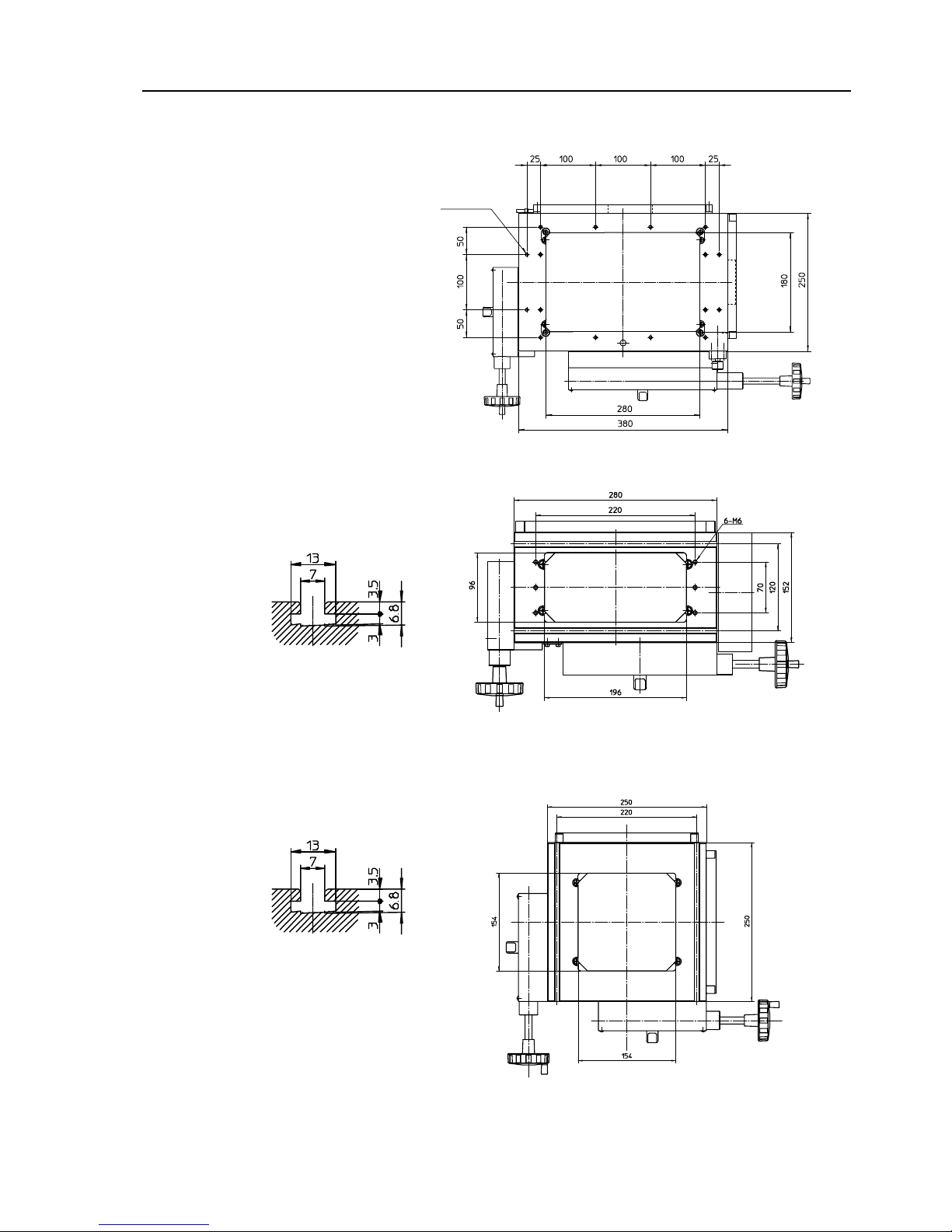
6. Specifications
6.4.2 Cross-travel stage
Traverse range : 200X100
Traverse range : 150X50
Traverse range : 100X100
16-M6,depth10
Detailed drawing of T-groove
Detailed drawing of T-groove
No.99MBA043A 6 - 19
Page 93

Traverse range : 50X50
Detailed drawing of T-groove
Fixed stage
Detailed drawing of T-groove
6 - 20 No.99MBA043A
Page 94

6. Specifications
6.5 Accessories
6.5.1 Standard accessories
M
ode
l No.
Order No.
Part Name
Quanti
ty
PJ-A301
0F
--200,-2
00E
PJ-A300
5F
-150,-15
0E
PJ-A301
0F
-100,-10
0E
PJ-A300
5D
-50,-50E
PJ-A300
5R
-50
PJ-A30
00
172-202
Projection lens 10x set
1
○ ○ ○ ○ ○ ○
930919
Shield plate 1
○ ○ ○ ○ ○ ○
930966 Power cord AC100 to 120V
930967
Power cord AC220 to 240V
998614
Power cord AC220 to 240V
1
(Select
any
one
kind)
○
○
○ ○ ○ ○
512305
Halogen bulb 24V150W500H 3
○ ○ ○ ○ ○ ○
384211
Tube fuse
BS SEMKO S506 5A
12BAE152
Tube fuse
51MS080H
2
(Select
any
one
kind)
○ ○ ○ ○ ○ ○
3020-1180-32
Grounding wire
1
990784
Grounding wire
383876
Vinyl cover 1
○ ○ ○ ○ ○ ○
538616
Alley spanner nominal 3
1
○ ○ ○
○ ○ ○
538615
Alley spanner nominal 2.5 1
○ ○ ○ ○ ○ ○
512926
Cap
4
○ ○ ○ ○ ○ ○
99MBA043A Operation Manual (this paper) 1
○ ○
○
○ ○ ○
472730 Warranty (large) 1
○ ○ ○ ○ ○ ○
359151
Spanner for leveling
1
○ ○ ○ ○ ○ ○
(Select
any
one
kind)
○ ○ ○ ○ ○ ○
No.99MBA043A 6 - 21
Page 95

6.5.2 Optional accessories
M
ode
l No.
PJ-A3010F
-200
PJ-A3005F
-150
PJ-A3010F
-100
PJ-A3005D
-50
Order No.
Part Name
Q
uan
tity
PJ-A3010F
-200E
PJ-A3005F
-150E
PJ-A3010F
-100E
PJ-A3005D
-50E
PJ-A3005R
-50
PJ-A3000
172-203
Projection lens 20x set
1
○ ○ ○ ○ ○ ○
172-204
Projection lens 50x set (with
hart-reflecting mirror)
1
○ ○ ○ ○ ○ ○
172-207
Projection lens 100x set
(with hart-reflecting mirror)
1
○ ○ ○ ○ ○ ○
172-229
Oblique reflecting
mirror(10x)
1
○ ○ ○ ○ ○ ○
172-230
Oblique reflecting
mirror(20x)
1
○ ○ ○ ○ ○ ○
172-116(172-117)
Standard scale (50mm or 2") 1
○ ○ ○ ○ ○ ○
172-118(172-119)
Reading scale
(200 mm or 8")
1
○ ○ ○ ○ ○ ○
172-161(172-162)
Reading scale
(300 mm or 12")
1
○ ○ ○ ○ ○ ○
172-160-2
Color filter
1
○ ○ ○
172-160-3
Color filter
1
○ ○ ○
176-106
Rotary table 1
○
○ ○ ○
172-196
Rotary table
1
○ ○ ○
176-105
Swivel center support
1
○ ○ ○
172-197
Swivel center support
1
○ ○ ○
176-107
Holder with clamp
1
○ ○ ○ ○ ○ ○
172-378
V block and clamp
1
○ ○ ○ ○ ○ ○
514304
Attachment board for Optoeye
sensor (with screws)
1
○ ○ ○
332-115-1 Optoeye A2 1
○ ○ ○
○ ○ ○ ○
264-140,-00,-01 QM-Data-200
○ ○ ○ A○
○ ○ ○
264-141,-00,-01 QM-Data-200
1
(Sele
ct
any
one
kind)
○ ○ ○
A
○
12AAD192 Connecting cable 1
○ ○ ○ ○
#
999678 Adapter 1
○
515530 Halogen bulb 24V 150W 50H
1
○ ○ ○ ○ ○ ○
Note)
For PJ-A3000, mark can't be mounted to them.
When the
mark is used, will be simultaneous with #mark Adapter(No.999678).
For PJ-A3005D-50E with A mark, I/F(MUX-10F), etc. w hich convert SPC output into RS232C are
necessity.
6 - 22 No.99MBA043A
Page 96

6. Specifications
No.99MBA043A 6 - 23
Model No.
PJ-A3010F
-200
PJ-A3005F
-150
PJ-A3010F
-100
PJ-A3005D
-50
Order No.
Part Name
Quanti-
ty
PJ-A3010F
-200E
PJ-A3005F
-150E
PJ-A3010F
-100E
PJ-A3005D
-50E
PJ-A3005R
-50
PJ-A3000
12BAE137
Scratch resistance stage
glass (50X50)
1
○ ○
12BAE138
Scratch resistance stage
glass (100X100)
1
○
12BAE139
Scratch resistance stage
glass (150X50)
1
○
12BAE140
Scratch resistance stage
glass (200X100)
1
○
12BAE141
Scratch resistance stage
glass (Fixed stage)
1
○
172-269
Machine stand
1
○ ○ ○ ○ ○ ○
172-267
Machine stand
1
○ ○ ○ ○ ○ ○
965013
SPC cable (2m)
2
D○ D○ D○ D○
C○ C○ C○
174-103-13
KS counter
1
○ ○ ○
C○ C○ C○
174-123-13
KC counter
1
○ ○ ○
○ ○ ○
12AAC038
2Dpak-M
1
12AAC035
2Dpak-P
1
B○
Note)
For PJ-A3005D-50E with B mark, connect with the output cable of MHD to it.
For PJ-A3010F-200 and PJ-A3005F-150 and PJ-3010F-100 with C mark, use by reconnecting Linea
r
Scale with the external counter.
D mark is for an angle counter output.
Page 97

6 - 24 No.99MBA043A
Model No.
PJ-A3010F
-200
PJ-A3005F
-150
PJ-A3010F
-100
PJ-A3005D
-50
Order No.
Part Name
Quantity
PJ-A3010F
-200E
PJ-A3005F
-150E
PJ-A3010F
-100E
PJ-A3005D
-50E
PJ-A3005
R
-50
PJ-A3000
512066 Overlay chart 1
512067 Overlay chart
1
512069 Overlay chart 1
512070 Overlay chart 1
512071 Overlay chart 1
512072 Overlay chart 1
512073 Overlay chart 1
512074 Overlay chart 1
512075 Overlay chart 1
512076 Overlay chart 1
512077 Overlay chart 1
932105 Overlay chart
1
12BAE144 Overlay chart
(
Continuous line and
Staggered cross-hair line
)
1
○ ○ ○ ○ ○ ○
 Loading...