

Page 1

LSM-6200
No.99MBC095A
SERIES No.544
Laser Scan
Micrometer
(Display Unit)
User's Manual
Read this User’s Manual thoroughly
before operating the instrument. After reading,
retain it close at hand for future reference.
Page 2
CONVENTIONS USED IN USER'S MANUAL
Safety Precautions
To operate the instrument correctly and safely, Mitutoyo manuals use various safety signs (Signal
Words and Safety Alert Symbols) to identify and warn against hazards and potential accidents.
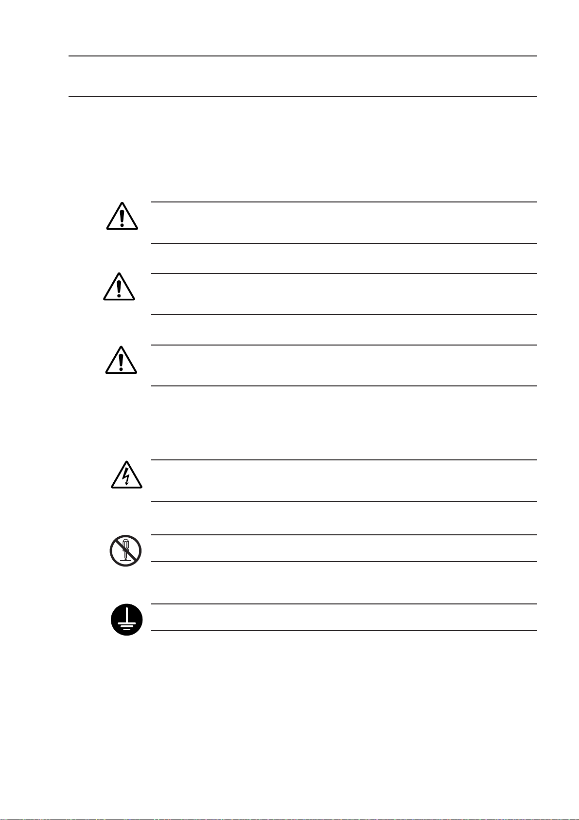
The following signs indicate general warnings:
Indicates an imminently hazardous situation which, if not avoided, will result in serious
DANGER
WARNING
CAUTION
injury or death.
Indicates a potentially hazardous situation which, if not avoided, could result in serious
injury or death.
Indicates a potentially hazardous situation which, if not avoided, may result in minor or
moderate injury or property damage.
The following signs indicate specific warnings or prohibited actions, or indicate a mandatory action:
Alerts the user to a specific hazardous situation. The given example means “Caution,
risk of electric shock”.
Prohibits a specific action. The given example means “ Do not disassemble”.
Specifies a required action. The given example means “Ground”.
No. 99MBC095A
i
Page 3
CONVENTIONS USED IN USER'S MANUAL
On Various Types of Notes
The following types of notes are provided to help the operator obtain reliable measurement data
through correct instrument operation.
IMPORTANT •An
of a task. You cannot disregard this note to complete the task.
• An important note is a type of precaution, which if neglected could result in a loss of
data, decreased accuracy or instrument malfunction/failure.
NOTE A note emphasizes or supplements important points of the main text. A note supplies infor-
mation that may only apply in special cases (e.g.. Memory limitations, equipment configurations, or details that apply to specific versions of a program).
TIP A tip is a type of note that helps the user apply the techniques and procedures described in
the text to their specific needs.
It also provides reference information associated with the topic being discussed.
Mitutoyo assumes no liability to any party for any loss or damage, direct or indirect,
caused by use of this instrument not conforming to this manual.
Information in this document is subject to change without notice.
© Copyright Mitutoyo Corporation2005. All rights reserved.
important note is a type of note that provides information essential to the completion
NOTES FOR EXPORTING
Before exporting this product confirm the final purpose of use at the export destination to
prevent the product from being used for developing weapons of mass destruction or military
affairs. In the case of export to the U.S., this product requires an application for prior
approval of CDRH (Center for Devices and Radiological Health) in FDA (Food and Drug
Administration). For detailed information consult a Mitutoyo sales office. Also, if this
product is exported with it incorporated in equipment, the final product requires an application for FDA approval. If this is the case, note that the client must file an application for
approval.
ii
No. 99MBC095A
Page 4

PRECAUTIONS
1. Safety Precautions
The Measuring Unit connected to the Display Unit uses a very low power laser.
Use of controls or adjustments or performance of procedures other than those specified
herein may result in hazardous radiation exposure.
1) An applicable laser product class of the IEC standard: a Class 2 laser product uses a
visible laser (maximum power: 1.3 mW for scanning; laser device: semiconductor laser;
wavelength: 650 nm).
2) Do not look directly into the laser beam. (Even if it seems that no light is being emitted
from the emission window, do not look into it.)
3) If measuring flat objects with mirror finishes, avoid looking at the reflection on the
surface.
4) Close the beam shutter when the instrument is not in use.
5) Do not remove the laser class identification labels attached to the Measuring Unit.
6) Before using this unit, carefully read the “Measuring Unit Specifications” and “Precautions on Use of Laser” sections provided in the manual supplied with the Measuring
Unit.
2. Before making the connection between the Measuring Unit and the Display Unit, turn off the
power. If an optional device is to be connected to this system, make sure that the optional
device is also turned off.
3. Firmly tighten the screws of the cable connectors and interfaces to ensure shielding.
4. Do not touch the terminals of the connectors, otherwise contact may be poor.
5. Positively ground the Display Unit.
6. An error display may appear during operation. However, it may not always indicate a fault. If
an error display appears, consult the “Maintenance and Inspection” section.
7. Unplug the power cord when a system failure is encountered.
Do not open the covers provided on the emission unit and reception unit.
No. 99MBC095A
iii
Page 5

INSTALLING CONDITIONS
The Mitutoyo Laser Scan Micrometer LSM-6100 series is both a precision optical instrument
and a precision electronic instrument, and this unit is the instrument suitable for indoor use as
well. Therefore, it must be carefully installed and the following conditions must be taken into
consideration to attain the highest possible accuracy.
1. Vibration
Install this unit if possible in a place where it will not be subject to vibration. If this unit is
used for a long period of time in an environment where there are significant vibrations, the
precision parts in this unit may be affected, resulting in the deterioration of measuring
accuracy.
If this unit has to be used in an environment where vibration is significant, measures such as
the laying of a vibration damping rubber pad under the unit must be applied to reduce the
effect of vibration.
2. Dust
Dust and airborne particles at the installation site adversely affect optical parts including the
protective glass and electronic parts of the Measuring Unit. Place this unit in a place with as
little dust and as few airborne particles as possible.
3. Direct sunlight
If this unit is subjected to direct sunlight, the heat may deform this unit and affect the
measuring accuracy.
4. Draft from air-conditioning equipment
5. Ambient temperature and humidity
WARRANTY
If this unit must be placed by a window where it will be subjected to direct sunlight, protect
the unit by shading it.
If the measuring area is subject to such as warm or cold draft from any air-conditioning
equipment, the laser beam may be artificially refracted due to the unevenness of ambient air
concentration, affecting the measurement accuracy.
If this is the case, block the draft in the mid-way to the measuring area by such as a curtain, etc.
This unit must be operated in an environment where the temperature is between 0 and 40˚C
and the humidity is between 35 and 85% RH. Avoid installing this unit where there is
significant temperature or humidity change.
Significant temperature and humidity changes may reduce measuring accuracy.
In the event that the Mitutoyo Laser Scan Micrometer (LSM) should prove defective in
workmanship or material, within one year from the date of original purchase for use, it will
be repaired or replaced, at our option, free of charge upon its prepaid return to us.
If the unit fails or is damaged because of the following causes it will be subject to a repair
change, even if it is still under warranty.
iv
1. Failure or damage due to inappropriate handling or unauthorized modification.
2. Failure or damage due to transport, droppage, or relocation of the machine after
purchase.
3. Failure or damage due to fire, salt, gas, abnormal voltage, or natural catastrophe.
This warranty is effective only where the machine is properly installed and operated following this manual.
No. 99MBC095A
Page 6

CONTENTS
CONVENTIONS USED IN USER'S MANUAL ................................................................. i
NOTES FOR EXPORTING ............................................................................................... ii
PRECAUTIONS ...............................................................................................................iii
INSTALLING CONDITIONS ........................................................................................... iv
WARRANTY.................................................................................................................... iv
1. INTRODUCTION................................................................................................... 1-1
2. SETUP .................................................................................................................. 2-1
1.1 Outline ........................................................................................................... 1-1
1.2 Foreword ....................................................................................................... 1-1
1.2.1 Measuring units available ................................................................. 1-1
1.2.2 Using the Measuring Unit separately ............................................... 1-1
1.3 Nomenclature ................................................................................................ 1-2
1.3.1 Display Unit....................................................................................... 1-2
1.3.2 Measuring Unit.................................................................................. 1-4
2.1 Unpacking and Acceptance Check............................................................... 2-1
2.2 Connecting the Cables ................................................................................. 2-1
2.3 Preliminary Checks ....................................................................................... 2-5
2.4 Initializing the LSM-6200 Display Unit .......................................................... 2-6
No. 99MBC095A
3. DISPLAYS AND KEY OPERATIONS.................................................................. 3-1
3.1 Outline of the Operation Modes ................................................................... 3-1
3.1.1 Measurement Principle ..................................................................... 3-1
3.1.1.1 Overview ................................................................................. 3-1
3.1.1.2 Setting the segment ............................................................... 3-3
3.1.1.3 Measurement interval (measurement time) ........................... 3-4
3.1.2 Outline of the Operation Modes ....................................................... 3-5
3.1.2.1 Basic setup mode ................................................................... 3-6
3.1.2.2 Calibration mode .................................................................... 3-6
3.1.2.3 Measuring condition setup mode ........................................... 3-6
3.1.2.4 Other setup mode................................................................... 3-6
3.1.2.5 Statistic display mode............................................................. 3-6
3.1.2.6 Measurement mode................................................................ 3-7
3.2 Techniques and Terminology of Setup Functions ........................................ 3-9
3.2.1 Program ............................................................................................ 3-9
3.2.2 Basic setup ..................................................................................... 3-10
3.2.3 Function setup ................................................................................ 3-11
3.2.4 Setups according to the property of each workpiece..................... 3-11
3.2.4.1 Transparent object (Workpiece that transmits light) ............ 3-11
3.2.4.2 Ultra-fine wire measurement ................................................ 3-14
3.2.5 Measurement of an odd-numbered-edge cutting tool .................... 3-16
3.2.6
3.2.7 Latch (holding) of the displayed value ........................................... 3-22
3.2.8 Automatic measurement with an edge specification...................... 3-23
3.2.9 GO/NG judgment ............................................................................ 3-24
3.2.10 Abnormal data elimination .............................................................. 3-26
3.2.11 Preset/Zero-set ............................................................................... 3-27
Measurement with two Measuring Units (dual-unit measurement)...
3.2.6.1 DW type ................................................................................ 3-18
3.2.6.2 DXY type .............................................................................. 3-19
3.2.6.3 DF type ................................................................................. 3-20
3-17
v
Page 7

3.2.12 Mastering ........................................................................................ 3-27
3.2.13 Reference value.............................................................................. 3-28
3.2.14 Data output conditions .................................................................... 3-28
3.2.15 Automatic workpiece detection <OD detection method,
Position detection method> ............................................................ 3-29
3.2.16 Group judgment .............................................................................. 3-31
3.2.17 Recording the amount of light ........................................................ 3-32
3.3 Outline of the Display Contents .................................................................. 3-33
3.3.1 Display unit ..................................................................................... 3-33
3.3.2 Data display unit ............................................................................. 3-33
3.4 Outline of Key Operations .......................................................................... 3-35
3.4.1 Description of key functions ........................................................... 3-37
3.4.2 Example key operations ................................................................. 3-41
4. SETTING UP THE MEASURING CONDITIONS ................................................. 4-1
4.1 Basic Setup ................................................................................................... 4-1
4.1.1 Outline of the basic setup procedure ............................................... 4-2
4.1.2 Description of each mode................................................................. 4-4
4.1.2.1 Selecting and setting the function in the B0 mode ................ 4-5
a. Setting the resolution (Guidance: RES) ............................ 4-5
b. Setting the number of blank-out digits (Guidance: BLN) .. 4-6
c. Putting a comma after the thousandths digit
(Guidance: (,)) ................................................................... 4-6
d. Setting the buzzer function (Guidance: BUZZER) ............ 4-7
e. Setting the display latch timer (Guidance: LATCH)........... 4-7
4.1.2.2 Selecting and setting the function in the B1 mode ................ 4-8
a. Setting the output function in the ready state
(Guidance: D.OUT) ............................................................ 4-8
b. Setting the analog output voltage if Err-0 occurs
(Guidance: ERR-0 V) ........................................................ 4-8
c. Selecting the display message if Err-0 occurs
(Guidance: ERR-0 D) ........................................................ 4-8
d. Selecting the display message at the start of measurement
(Guidance: RUN D) ........................................................... 4-9
e. Selecting the averaging method (Guidance: AVG.M)....... 4-9
f. Setting the GO/NG judgment method
(Guidance: JDG.M) ............................................................ 4-9
g. Setting whether the target value is copied to the reference
value (Guidance: COPY)................................................. 4-10
4.1.2.3 Selecting and setting the function in the B2 mode .............. 4-11
a. Setting the workpiece type (Guidance: WORK.P) .......... 4-11
b. Setting whether to perform ultra-fine wire measurement
(Guidance: FINE) ............................................................. 4-11
c. Setting the simultaneous measurement
(Guidance: PROG) .......................................................... 4-12
d. Setting the dual-unit measurement (Guidance: TYPE) ... 4-12
e. Setting the DXY-type calculation (Guidance: CALC)...... 4-13
f. Selecting the method of specifying segments
(Guidance: SEG) ............................................................. 4-13
4.1.2.4 Selecting and setting the function in the B3 mode .............. 4-14
a. Setting the abnormal value elimination function
(Guidance: ADE) ............................................................. 4-14
vi
No. 99MBC095A
Page 8

b. Setting the automatic workpiece detecting function
(Guidance: AWDT) .......................................................... 4-14
c. Setting the number of scans (Guidance: SCAN) ............ 4-15
d. Setting the group judgment (Guidance: GTJ) ................. 4-15
e.
Setting the group judgement output (Guidance: GTJ D)...
f. Setting the odd-numbered-edge cutting tool measurement
function (Guidance : TOOL)............................................ 4-16
4.1.2.5 Selecting and setting the function in the B4 mode .............. 4-17
a. Setting the use of RS-232C port
(Guidance: RE-232C) ...................................................... 4-17
b. Setting the RS-232C communication baud rate
(Guidance: BAUD)........................................................... 4-17
c. Setting the RS-232C communication data bits
(Guidance: LENGTH) ...................................................... 4-17
d. Setting the RS-232C communication parity bit
(Guidance: PARITY)........................................................ 4-18
e. Setting the delimiter for communication
(Guidance DELIMT) ......................................................... 4-18
f. Setting the RS-232C line control
(Guidance: CONTRL) ...................................................... 4-18
4.1.2.6 Selecting and setting the function in the B5 mode .............. 4-19
a. Setting the RUN input function from the I/O interface
(Guidance: RUN) ............................................................. 4-19
b. Setting the PSET input function from the I/O interface
(Guidance: PSET) ........................................................... 4-19
c. Setting the GO output function from the I/O interface
(Guidance: GO) ............................................................... 4-20
4.1.2.7 Selecting and setting the function in the B6 mode .............. 4-20
a. Setting the use of DCU (Guidance: DCU) ...................... 4-20
4.1.2.8 Setting in the B7 mode (expanded items) ........................... 4-21
a. Setting expanded items (Guidance: ADD) ...................... 4-21
b. Reservation (Guidance: SEG_LIM)................................. 4-21
c. Reservation (Guidance: SEG_ER0) ................................ 4-21
d. Reservation (Guidance: SEG_COR)............................... 4-21
e. SHL setting (Guidance: SHL).......................................... 4-21
f. Setting for detecting dirty protection glass
(Guidance: DIRT) ............................................................ 4-22
g. Setting the measurement mode (Guidance: DLC) .......... 4-22
h. Space for additional functions (Guidance: A.5V) ............ 4-23
i. Space for additional functions (Guidance: A.0V) ............ 4-23
j. Space for additional functions (Guidance: A2.0V) .......... 4-23
k. Setting the STB length of I/O analog interface
(Guidance: STB).............................................................. 4-23
l. Setting the input software filter (Guidance: IFF) ............. 4-23
m. Setting the application range of calibration
(Guidance: CAL).............................................................. 4-24
n. Setting the application range of presetting and mastering
(Guidance: PST).............................................................. 4-24
o. Setting the number of programs to be used
(Guidance: PRGM).......................................................... 4-24
4.2 Calibration ................................................................................................... 4-25
4.2.1 Calibration gages and gage stand ................................................. 4-25
4-15
No. 99MBC095A
vii
Page 9

4.2.2 Entering the calibration mode......................................................... 4-25
4.2.3 Combined calibration ...................................................................... 4-27
4.3 Positioning a Gage or a Workpiece............................................................ 4-29
4.4 How to read-in the amount of light ............................................................. 4-29
4.5 Setting Up the Functions ............................................................................ 4-31
4.5.1 Outline of the function setup mode ................................................ 4-31
4.5.2 Outline of each function setup mode ............................................. 4-32
4.5.3 Function setup mode ...................................................................... 4-33
4.5.3.1 F0: Setting the segment ....................................................... 4-34
4.5.3.2 F1:
4.5.3.3 F2: Setting the GO/NG judgment criteria ............................. 4-38
4.5.3.4 F3: Setting the reference value ............................................ 4-42
4.5.3.5 Analog voltage output and scale value ................................ 4-43
4.5.3.6 F4: Setting the preset/zero-set values ................................. 4-45
4.5.3.7 F5: Setting the data output conditions ................................. 4-47
4.5.3.8 F6: Setting the sample measurement .................................. 4-48
4.5.3.9 F7: Automatic workpiece detection setting .......................... 4-50
4.5.3.10 F8: Setting the group judgment............................................ 4-51
4.5.3.11 Confirming the function setup contents................................ 4-52
5. MEASUREMENT MODE ...................................................................................... 5-1
5.1 Outline of the Measurement Mode ............................................................... 5-1
5.1.1 Settings made in the measurement mode ....................................... 5-1
5.1.1.1 Setup operation from the arrow key....................................... 5-2
5.1.1.2 Setup that can be made directly from each setup item key .. 5-4
5.2 Other Functions ............................................................................................ 5-6
5.2.1 Key lock ............................................................................................ 5-6
5.2.2 Displaying the measuring position .................................................... 5-6
5.3 Applied Measurement ................................................................................... 5-7
5.3.1 OD measurement of a precision-machined workpiece .................... 5-7
5.3.2 Measurement of magnet coil wire that runs at high speed.............. 5-8
5.3.3 Measurement of the lead pitch of a multiple-pin IC ....................... 5-10
5.3.4 Applied Measurement with Preset/Zero-Set Functions.................. 5-12
5.3.5 Sample measurement..................................................................... 5-16
5.3.6
5.3.7 Applied measurement with automatic workpiece detection ........... 5-22
5.3.8 Applied measurement on a stepped round bar .............................. 5-24
Application of the odd-numbered-edge cutting tool measurement ...
5.3.6.1 Odd-numbered-edge cutting tool outside diameter
5.3.6.2 Odd-numbered-edge cutting tool run-out measurement ...... 5-20
Setting the measurement interval (measurement time) ...
measurement........................................................................ 5-18
4-36
5-18
viii
6. INTERFACE UNIT ................................................................................................ 6-1
6.1 Standard Interface ........................................................................................ 6-1
6.1.1 I/O Analog Interface.......................................................................... 6-1
6.1.1.1 External view of the connector ............................................... 6-1
6.1.1.2 Terminal names ...................................................................... 6-2
6.1.1.3 Input/output equivalent circuit................................................. 6-2
6.1.1.4 Timing chart ............................................................................ 6-5
6.1.2 RS-232C Interface ............................................................................ 6-7
6.1.2.1 Specifications.......................................................................... 6-7
6.1.2.2 Connections ............................................................................ 6-8
6.1.2.3 Printer interface .................................................................... 6-10
No. 99MBC095A
Page 10

6.1.2.4 RS-232C/GP-IB commands ................................................. 6-10
6.1.2.5 List of commands ................................................................. 6-12
6.1.2.6 List of response commands if an error occurs .................... 6-14
6.1.2.7 Format of response commands ........................................... 6-15
6.1.2.8 Other commands .................................................................. 6-16
6.1.2.9 Details of command descriptions ......................................... 6-17
6.2 Optional Interface........................................................................................ 6-24
6.2.1 Digimatic Output Unit interface....................................................... 6-24
6.2.1.1 Method of use....................................................................... 6-24
6.2.1.2 Name of each part................................................................ 6-25
6.2.1.3 I/O specifications .................................................................. 6-26
6.2.1.4 Timing chart .......................................................................... 6-27
6.2.1.5 Data format ........................................................................... 6-28
6.2.2 Second Analog I/O Interface .......................................................... 6-30
6.2.2.1 Method of use....................................................................... 6-30
6.2.2.2 Name of each part................................................................ 6-30
6.2.2.3 I/O Interface .......................................................................... 6-31
6.2.2.4 Analog output ....................................................................... 6-39
6.2.3 BCD interface ................................................................................. 6-40
6.2.3.1 Method of use....................................................................... 6-40
6.2.3.2 Name of each part................................................................ 6-40
6.2.3.3 Specification ......................................................................... 6-41
6.2.4 GP-IB interface ............................................................................... 6-46
6.2.4.1 Method of use....................................................................... 6-46
6.2.4.2 Name of each part................................................................ 6-46
6.2.4.3 Specification ......................................................................... 6-47
6.2.4.4 Functions .............................................................................. 6-49
6.2.4.5 Operations ............................................................................ 6-50
6.2.5 Dual-type add-on unit ..................................................................... 6-50
6.3 Installing the Optional Interface Unit .......................................................... 6-51
6.3.1 Digimatic Output Unit...................................................................... 6-52
6.3.2 Second Analog I/O, BCD, and GP-IB interfaces ............................ 6-52
No. 99MBC095A
7. INSPECTION AND MAINTENANCE.................................................................... 7-1
7.1 Display Unit ................................................................................................... 7-1
7.1.1 Display check.................................................................................... 7-1
7.1.2 Cleaning method............................................................................... 7-1
7.2 Error Messages and Remedies .................................................................... 7-2
7.3 Troubleshooting and Remedies .................................................................... 7-3
7.4 Fuse replacement ......................................................................................... 7-4
8. SPECIFICATIONS ................................................................................................ 8-1
8.1 LSM-6200 Display Unit ................................................................................. 8-1
9. RESTRICTIONS ASSOCIATED WITH THE COMBINATION OF FUNCTIONS,
TABLES OF THE BASIC SETUP MODES ......................................................... 9-1
9.1 Restrictions Associated with the Particular Combination of Functions ........ 9-1
9.2 List of Setup Modes ...................................................................................... 9-2
9.2.1 List of basic setup modes................................................................. 9-3
9.2.2 List of calibration functions ............................................................... 9-5
9.2.3 Reading in the amount of light ......................................................... 9-5
9.2.4 List of function setup modes ............................................................ 9-6
ix
Page 11

MEMO
No. 99MBC095A
Page 12

INTRODUCTION
1
1.1 Outline
This system is an accurate, non-contact measurement system capable of measuring workpiece
dimensions at a high speed using a highly directional scanning laser beam.
This non-contact optical measuring system is capable of measuring workpieces which are
difficult to measure with conventional measuring instruments. It performs simple and
accurate measurement of brittle or elastic objects, objects at high temperature, objects which
must be kept clean, and soft objects which may be deformed and suffer dimensional changes
under the measuring forces used.
1.2 Foreword
This user’s manual primarily explains the functions of the Display Unit. For information
about the safety precautions, specifications, dimensions, standard accessories, and options for
each Measuring Unit, refer to the user’s manual supplied with the Measuring Unit.
This chapter describes the Laser Scan Micrometer (LSM) models and
nomenclature of the Display unit and the Measuring unit.
1.2.1 Measuring units available
This Display Unit can be used with the following Measuring Units.
sledoM
S005-MSL
S105-MSL
S305-MSL
S605-MSL
S215-MSL
S615-MSL
1.2.2 Using the Measuring Unit separately
All models, excluding the LSM-500S, can be used separately (the laser emission unit and
reception unit can be separated) by removing the mount from the Measuring Unit.
For information about using an LSM separately, refer to the measuring unit user’s manual.
No. 99MBC095A
1 - 1
Page 13
1.3 Nomenclature
This section gives the name of each part in the LSM system.
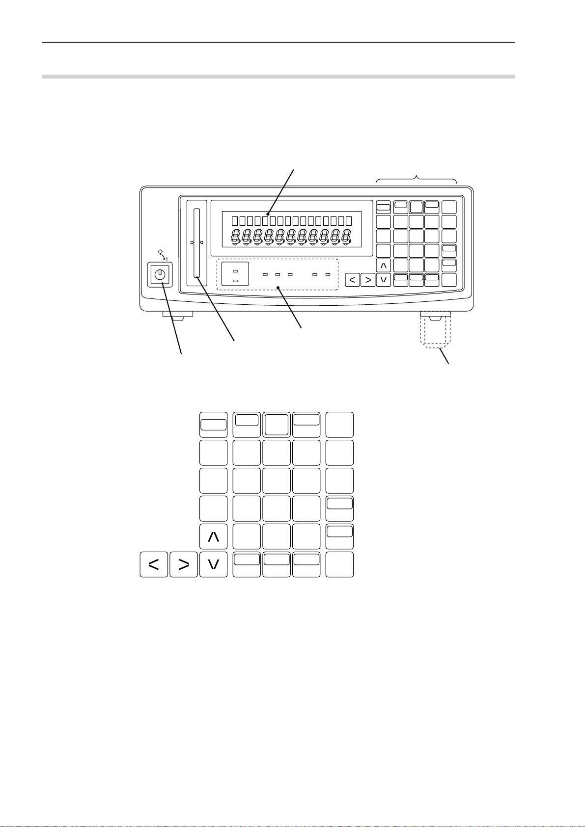
1.3.1 Display Unit
(1) Front panel
(2) Displays and keys
Mitutoyo
Power switch
SHIFT
READ
Data display
LASER SCAN MICROMETER LSM-6200
PROG.
LOCK CAL P.SET S.E DUAL
LD1 ON
LD2 ON
BUSYRUN+NGGO-NG
Status indicator LEDs (lit/unlit)
Workpiece position indicator LED
DATA C
RUN
7
C.RUN
8
S.PR
PRINT
SET
C9
Operation keys
DATA C
SHIFT
RUN
READ
7
H.CAL
4
L.CAL
1
LOCK
UNIT
C.RUN
8
5
2
•0
A.CL
M.CL
S.PR
PRINT
+/-
STAT
S.E
SET
C9
6
LIMIT
P.S V
3
P.SET
MASTER
REF
ENT
Stand
1 - 2
H.CAL
L.CAL
4
1
LOCK
UNIT
5
2
•0
A.CL
M.CL
6
3
+/-
STAT
S.E
LIMIT
P.S V
P.SET
MASTER
REF
ENT
No. 99MBC095A
Page 14
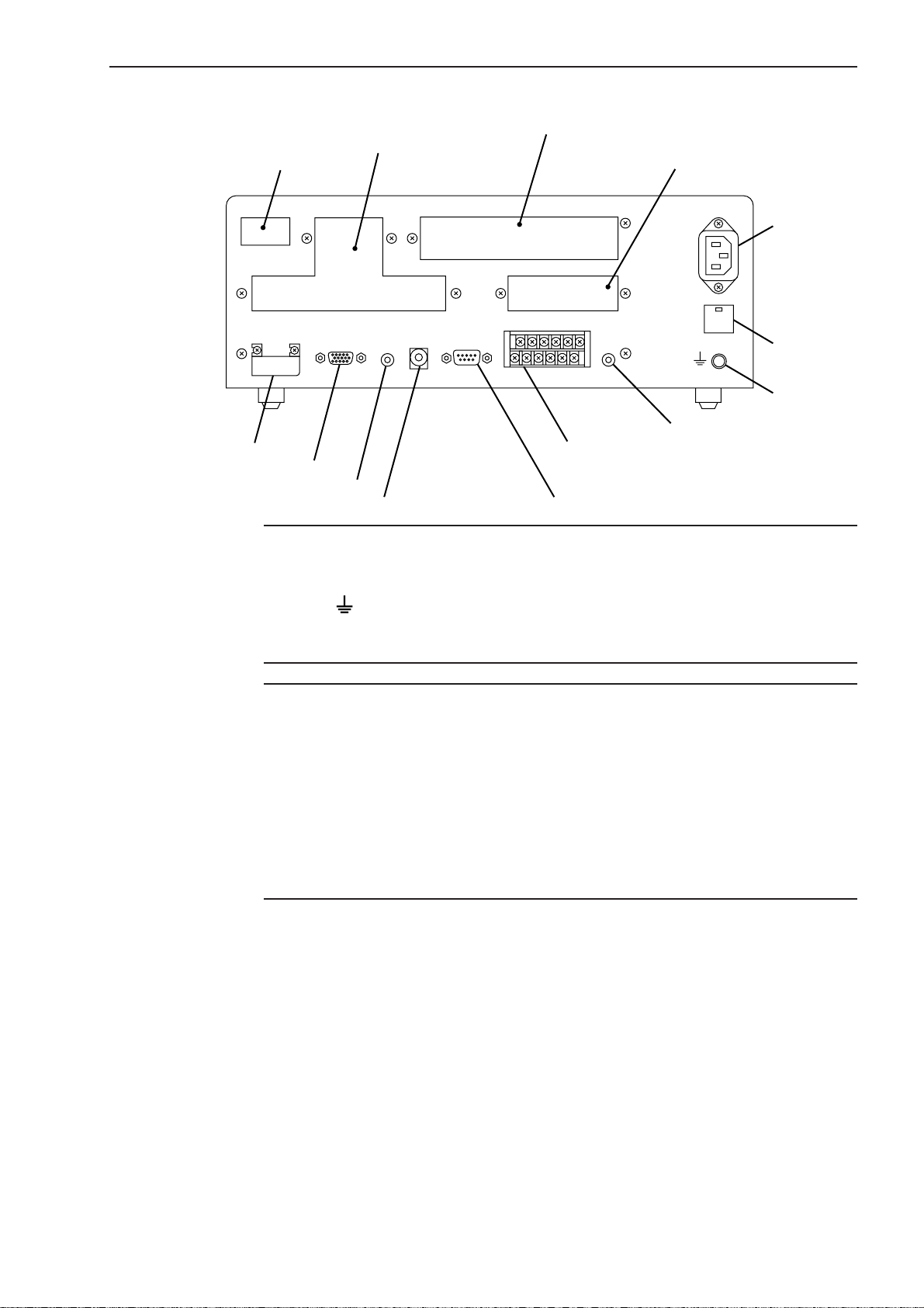
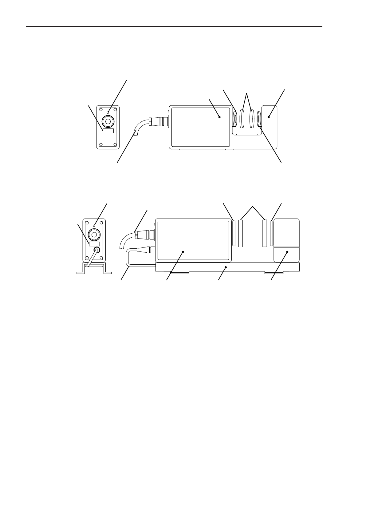
(3) Rear panel
1. INTRODUCTION
Add-on Unit installation space
Name plate
ID Unit Protection cover
Signal cable connector
Scanning signal connector
Remote interlock connector
TIP 1. A label which describes the terminal block name “I/O ANALOG” can be seen if the
Optional Dual-type
ID UNIT 1
ID
TRANSMITTER-1
SCAN SIG.-1
REMOTE INTERLOCK
Optional Interface add-on space
(Second Analog I/O Unit, BCD Output Unit, GP-IB Unit)
Optional Digimatic Output Unit
add-on space
AC power inlet
FOOT
SW.
I/O ANALOGRS-232C
Analog I/O connector
RS-232C connector
Foot switch
Fuse holder
AC power inlet
protective cover of the Analog I/O terminal block is opened. Use this for wiring.
2. The terminal located at the left end of the power input terminal and marked (by a
symbol ) is the grounding terminal to keep the potential of signal line of this
unit equal with other instrument connected. It is used to enhance resistance
against electrical interference.
NOTE Precautions for wiring the terminal block
1. If wiring the I/O analog terminal and Power input terminal, do not directly touch the
output terminals of the terminal block by hand, which has static charges, because
the internal circuit may be damaged by static discharge.
If your hands are charged, discharge the static energy by touching the metallic
surface of the Display Unit in advance. In addition, unplug the power cable from
the outlet before commencing wiring.
2. After wiring has been completed, close the protective cover.
3. Do not touch the input terminals on the terminal block during operation, otherwise
an operation error may result.
No. 99MBC095A
1 - 3
Page 15
1.3.2 Measuring Unit
(1) Measuring Unit (integrated-type Measuring Unit)
LSM-500S
Laser emission indicator LED
Serial number label
Emission window
Emission unit
Mitutoyo
LSM-500S
LASER SCAN MICROMETER
Lens caps
Reception unit
Signal cable
(2) Measuring Unit (separate-type Measuring Unit)
LSM-501S, 503S, 506S, 512S, 516S
Laser emission
indicator LED
Serial number label
Connection cable
Signal cable
Mitutoyo
LASER SCAN MICROMETER
Emission window
LSM-501S
Mount
Reception unitEmission unit
Shutter
Reception window
Reception window
1 - 4
No. 99MBC095A
Page 16

SETUP
2
This chapter describes the connection between the Display Unit and
Measuring Unit.
2.1 Unpacking and Acceptance Check
Your LSM has been thoroughly inspected prior to shipment. The mechanical, electrical, and
optical systems are guaranteed to operate properly.
Unpack the package and check that the accessories, for the Display Unit or Measuring Unit,
and signal cables, etc., are intact and not damaged.
Contact Mitutoyo if anything is damaged or missing.
2.2 Connecting the Cables
Make sure that the power switch is turned off (turn the key switch counterclockwise to align
with “O”, then pull it out), then connect the cables according to the following procedure.
Step 1: Integrating the option interface
For the option interface (Dual-type Add-on Unit, Second Analog I/O Unit, BCD
Output Unit, GP-IB Unit, and Digimatic Output Unit) to become available with the
LSM, it must be installed by referring to Section 6.3 “Installing the Optional Interface Unit”.
For information about the setup switches on the BCD and GP-IB interface units refer
to Section 6.2.3, “BCD Interface” and Section 6.2.4, “GP-IB Interface”, respectively.
No. 99MBC095A
2 - 1
Page 17
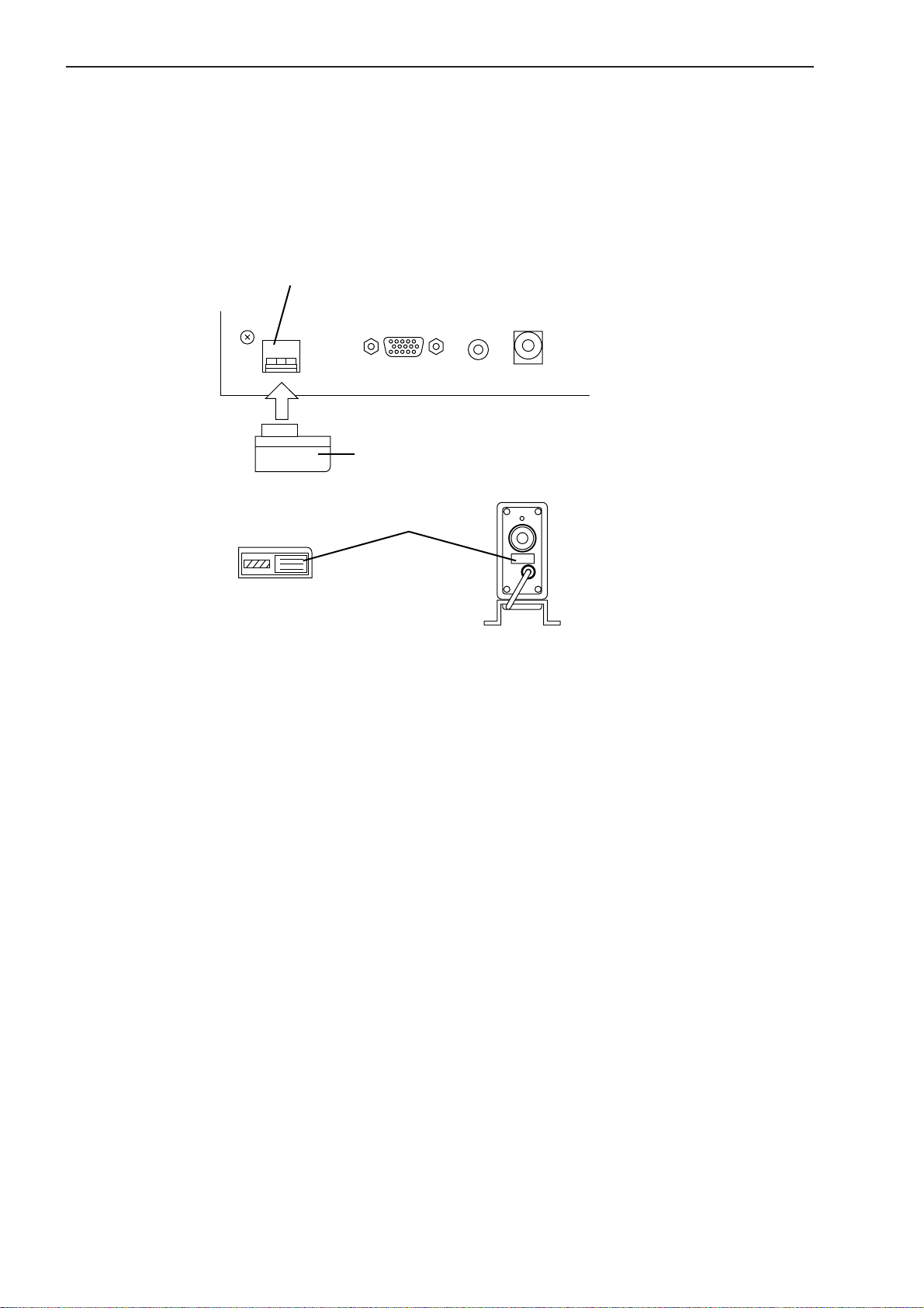
Step 2: Attaching the ID unit
1. Loosen the two screws that secure the ID unit protection cover at the left on the
real panel of the Display Unit and remove the cover by sliding it rightward.
2. Remove the dummy ID unit (amber) that has been mounted at the left of the
“TRANSMITTER-1” connector on the rear panel of the Display Unit, then insert
the ID unit (beige) that comes in the same package as the Measuring Unit.
This ID unit stores critical data that ensures the accuracy of the Measuring Unit
and has the same serial number as the accompanying Measuring Unit. Confirm that
these two numbers are identical before inserting the ID unit.
ID unit slot
SCAN SIG.-1ID UNIT 1
TRANSMITTER-1
ID
ID unit Measuring unit
ID unit
Serial number label
REMOTE INTERLOCK
If a Dual-type Add-on Unit is used, install the ID unit in the ID UNIT 2 slot above
the ID UNIT 1.
3. Replace and secure the ID unit protection cover revering the procedures in step 1
above.
2 - 2
No. 99MBC095A
Page 18
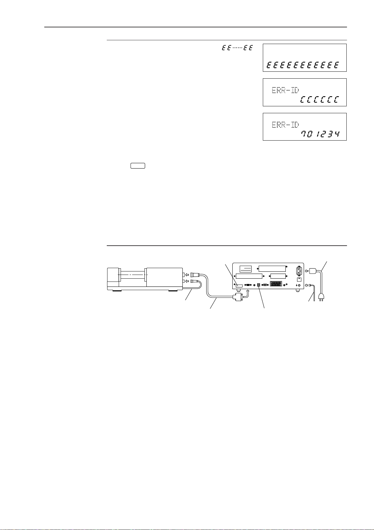
2. SETUP
IMPORTANT • If the dummy ID unit is still mounted, “ ”
is displayed in the lower section of the display. If
this is the case, turn off the power and replace the
dummy ID unit with a proper ID unit.
• If the ID unit has not been installed, an error
display as shown at the right will appear in the
upper section of the data display unit and the
operation of this unit stops.
• If the ID unit is not installed or if the serial number of
the Measuring Unit is not consistent with that on the
ID unit, the system will not work and an error code
as shown at the right will be displayed at power on.
At the same time, the 6-digit serial number of the
measuring unit is displayed for confirmation.
If the
automatically started. However, the measuring accuracy can not be guaranteed. If
the optional dual-type add-on unit is used to perform measurement with two
Measuring Units, make sure that the serial numbers of the two Measuring Units,
which are connected to the “TRANSMITTER-1” connector and “TRANSMITTER-2”
connector, are identical. If neither of the two Measuring Units has a serial number
identical to that of the ID unit, a serial number of the Measuring Unit on the
“TRANSMITTER-1” side will be displayed in the upper display section, and that of
the Measuring Unit on the “TRANSMITTER-2” side will be displayed in the lower
display section.
key has been pressed to enter the ready state, measurement can be
C
PROG
PROG
PROG
No. 99MBC095A
ID unit
ID
Connecting cable
Signal cable
GND lead wire
Remote interlock
Step 3: Connecting the connecting cable (except for the LSM-500S)
Connect the cable which runs from the base of the Measuring Unit to the lower
connector (5-pin) on the rear panel of the emission unit.
Step 4: Connecting the signal cable
Insert the round plug (12-pin) of the signal cable into the upper connector (12-pin)
on the rear panel of the emission unit. Tighten the ring screw to firmly secure the
connectors.
Insert the square connector (15-pin) on the other end of the signal cable into the
connector “TRANSMITTER-1” at the upper left of the display rear panel and tighten
the securing screws.
If measurement is performed with two Measuring Units while using the optional
dual-type add-on unit, plug the cable from the second Measuring Unit into the
“TRANSMITTER-2” connector, then firmly tighten the screws.
Step 5: Connecting the power cord and GND lead wire
Connect the supplied power cord to the AC connector at the upper right on the rear
panel of the Display unit. Also be sure to ground the Display unit with the GND lead
wire for improved resistance to noise.
Power
cord
2 - 3
Page 19
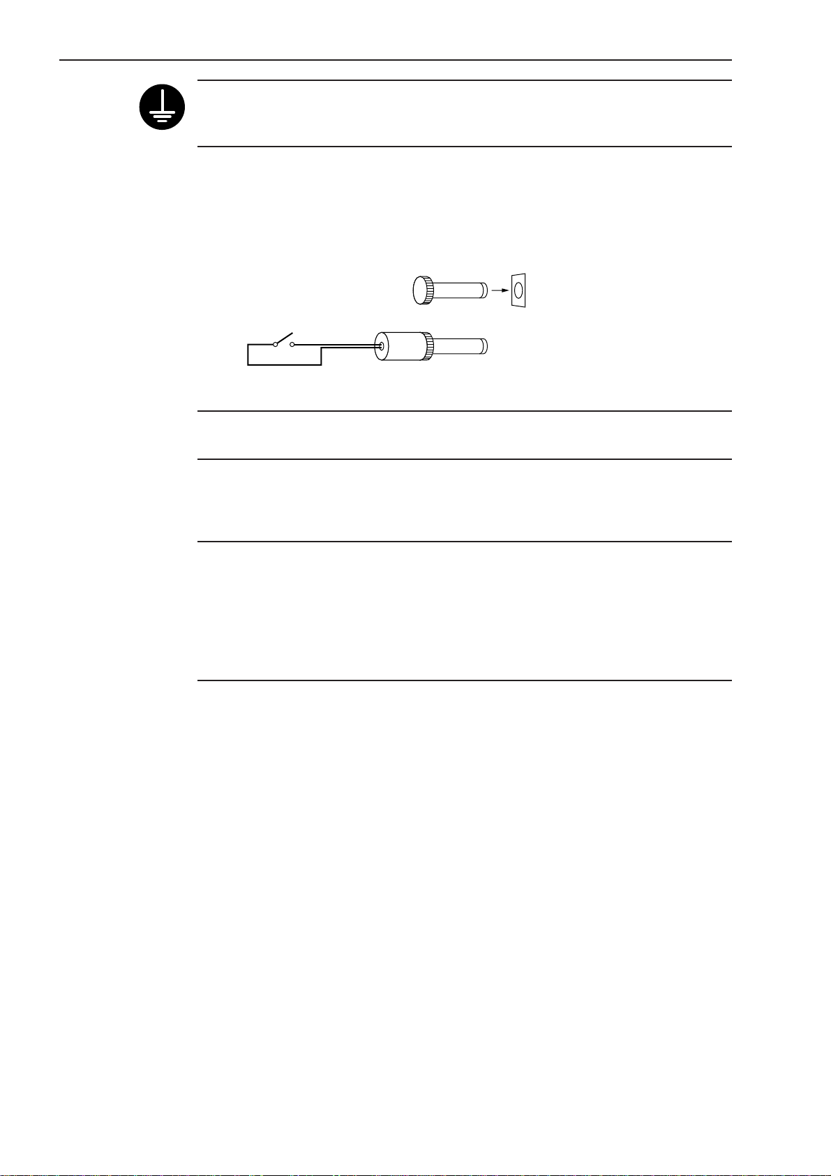
Terminal to which a grounding wire is connected.
(
)
Ground the system using the provided grounding wire to avoid the effect of interference noise caused in the setup environment.
Step 6: Checking the remote interlock connector
Make sure that the short-circuiting pin is inserted into the “REMOTE INTERLOCK”
connector on the rear panel of the Display Unit. If this short-circuiting pin is not
inserted, laser emission is disabled, even if the power switch is on.
To emergency stop laser emission, refer to the following diagram.
Switch ON: Laser emission ON
Switch OFF: Laser emission OFF
Short-circuiting pin
Switch
5V, 3mA
Applicable connector: PJ-2
Manufacturer: Sato Parts
NOTE Recovering operation is not guaranteed. Never use this function for other than
emergency stop.
Step 7: Connecting the interface
For information about the procedure used to connect the interface, refer to Section
6.1.1, “I/O Analog Interface” and Section 6.1.2, “RS-232C Interface”.
NOTE 1. Note the following when connecting the signal cable.
For information about the precautions to be observed when connecting the signal
cable refer to the measuring unit user’s manual.
2. Note the following when making cable connections.
Always make connection or disconnection with the power cord unplugged. In
addition, before connecting to the interface make sure that the power to all other
units connected or to be connected are also off.
2 - 4
No. 99MBC095A
Page 20
2.3 Preliminary Checks
The necessary connections should be completed by following the procedure described in the
previous chapter. Simplified operation checks are described here.
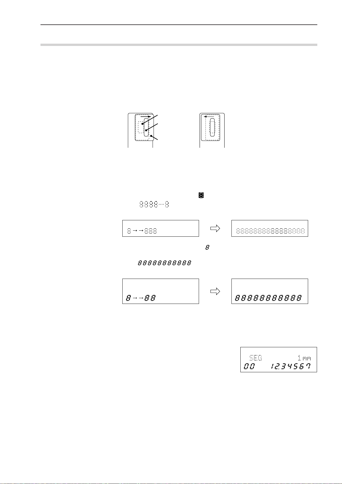
Step 1: Fully open the lens cap and shutter of the Measuring Unit.
Fully open the lens caps and beam shutters of both the emission unit and reception
unit to ready the laser beam for emission.
The lens caps should be completely removed, and the shutters should be as shown in
the diagram below.
If the shutter is closed If the shutter is open
Step 2: Power on
• Turn the power key switch on the Display Unit clockwise until it is in the I
(power on) position and the power is on.
• This unit enters the self check mode and all the LEDs and segments turn on. They
will turn off shortly, and eights will be displayed in the upper display section.
When is displayed across the upper display section, the unit will turn
off shortly. This is followed by the self check on the lower display section.
2. SETUP
Emission window
Shutter window
Shutter
PROG PROG
PROG
• In the lower display section eights will appear sequentially from the left to
right.
• After is displayed across the lower display section, it will
turn off shortly.
PROG PROG
• Measurement is started.
The LD1 ON (LD1 ON and LD2 ON in the dual-unit measurement) LED turns on
and the BUSY LED starts flashing to indicate the measurement has started from
the ready state.
Since the objective segment has been set to
PROG
“SEG 1” at the factory, the displayed measurement shows the laser scanning range of the
Measuring Unit.
Here, the Display Unit is found to be normal
because the scanning range is displayed.
Proceed to Chapter 3, “DISPLAYS AND KEY
OPERATIONS”, to custom set up each
function.
No. 99MBC095A
2 - 5
Page 21
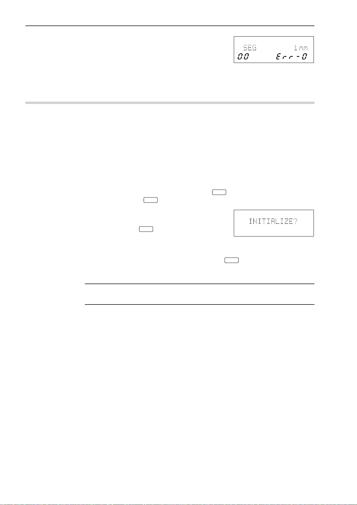
• An error may be displayed at this stage,
however, the display at the right is not actually
an error. Check the shutter of the Measuring
Unit.
For information about other errors that may result refer to Section 8.3, “Error
Messages and Remedies”.
2.4 Initializing the LSM-6200 Display Unit
After making sure that this unit is operating normally, initialize the Display Unit so it can
recognize the Measuring Unit(s) to be used.
Initialization of the Display Unit is also required if the Measuring Unit needs to be changed.
In addition to replacing the ID unit that is associated with the Measuring Unit, initialize the
Display Unit (i.e. restore the factory setups) with the following procedure.
The initialization procedure is as follows:
Step 1: Turn off the power and connect the Measuring Unit with the ID unit that comes with
the Measuring Unit installed.
PROG
Step 2: Turn on the power while holding down the
Hold down the
key for approximately 2 seconds, even after the power is on.
C
Step 3: When the self check has been completed, the
key.
C
PROG
display shown at the right will appear. To initialize, press the
key. When the initialization
ENT
process has been completed, the display restors
the initial conditions that existed just after the
power on.
To abort initialization press a key other than the
key or turn the power off.
ENT
In the former case the initialization process will be aborted and the initial display at
power-on will be restored.
NOTE Initialization will clear all the customer setup data and will restore the factory-setups.
Customize the setups again as necessary.
2 - 6
No. 99MBC095A
Page 22
DISPLAYS AND KEY
3
OPERATIONS
This Display Unit is provided with many useful functions that can be
customized according to the user's needs.
This chapter describes these functions and key operations.
3.1 Outline of the Operation Modes
3.1.1 Measurement Principle
In order for the user to understand the measurement principle of the LSM, the following
paragraphs describe about the system block diagram, segments (measurement positions) and
measurement interval (measurement time).
3.1.1.1 Overview
Unlike light emitted from natural sources, a laser provides extremely fine, rectilinear beams
which do not diffuse (coherent light beams).
Using the properties of the laser beam, the Mitutoyo Laser Scan Micrometer (LSM) moves a
scanning laser beam over the workpiece and determines its dimensions by measuring the
duration in which the beam is obstructed by the workpiece.
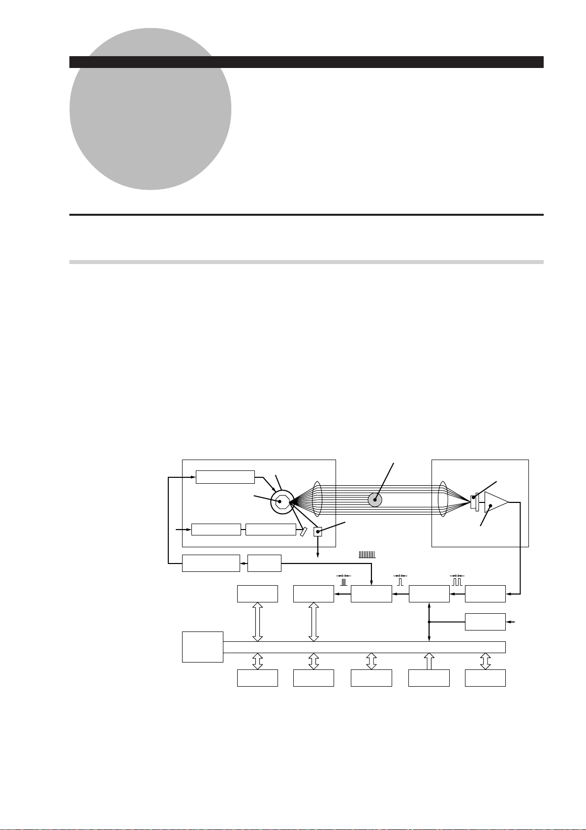
No. 99MBC095A
Emission unit Reception unit
Polygon mirror
Polygon mirror
Laser power source Semiconductor laser
MP
Motor driving pulse
CPU
Motor Colimator lens
Clock pulse
ROM RAM
Data display
Keyboard
Counter
RS-232C
Photoelectric element
(reset signal generation)
RS
Gate Edge signal
I/O analog
interface
Workpiece
Segment
selection circuit
Foot switch
Condenser lens
Amplifier
ttt
Edge signal
Option I/F
Reception
device S
RS
3 - 1
Page 23

The configuration of the system is shown in the above block diagram. A laser beam emitted
from the laser oscillator is directed at the polygon mirror which rotates at high speed and is
synchronized by clock pulses. The laser beam that is reflected by the polygon mirror is then
collimated by the collimator lens towards the workpiece. As the polygon mirror rotates, this
horizontal beam scans the workpiece and the beam not obstructed by the workpiece will
reach the photoelectric element through the condenser lens and induce an output voltage in
the photoelectric element. The output voltage will change according to the duration over
which the laser beam is obstructed. Counting pulses generated during that period are used to
determine the dimension of the obstructed portion. This data is sent to the CPU for processing and the dimensions are displayed digitally.
Consequently, either the dimensions of the workpiece (shadowed areas) or workpiece
clearances (highlighted areas) can be determined by specifying the segments to be measured.
TIP In the system block diagram described in the previous page, the laser beam passed
through the collimator lens is made parallel and, at the same time, stopped down so
that the beam diameter is minimized at the measurement position.
3 - 2
No. 99MBC095A
Page 24
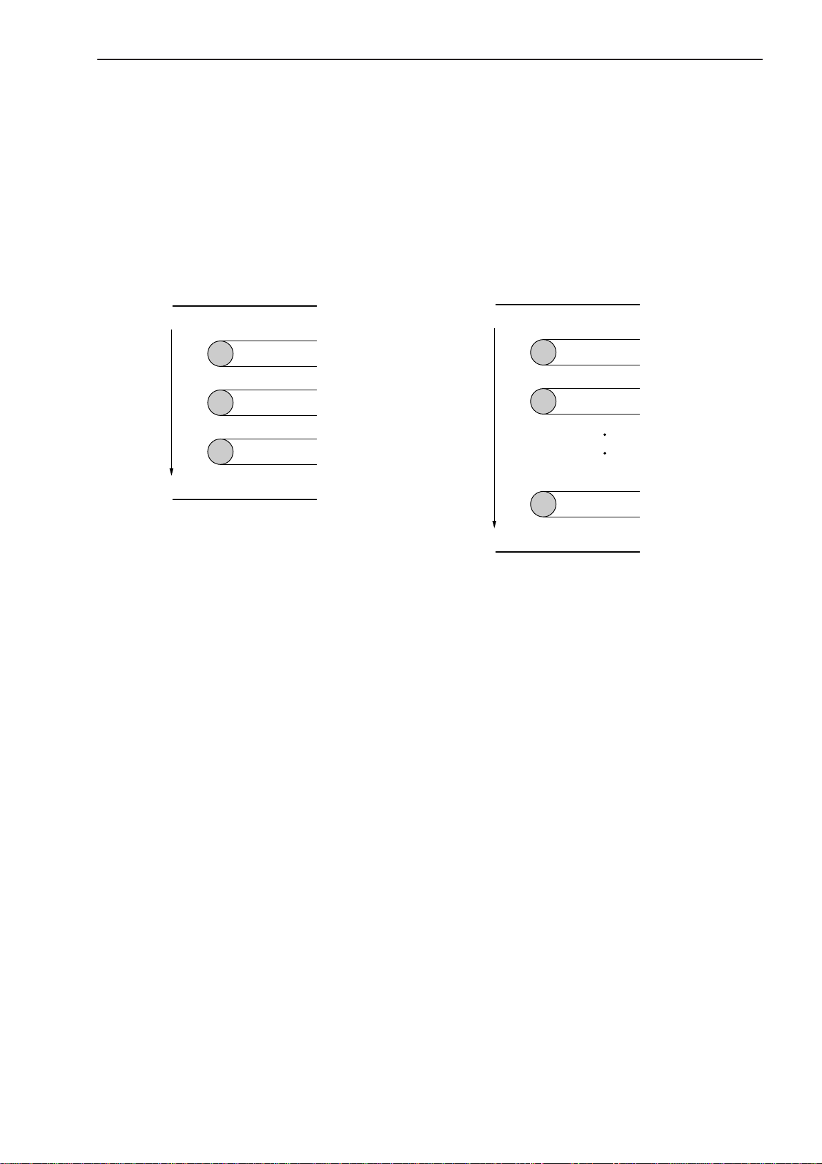
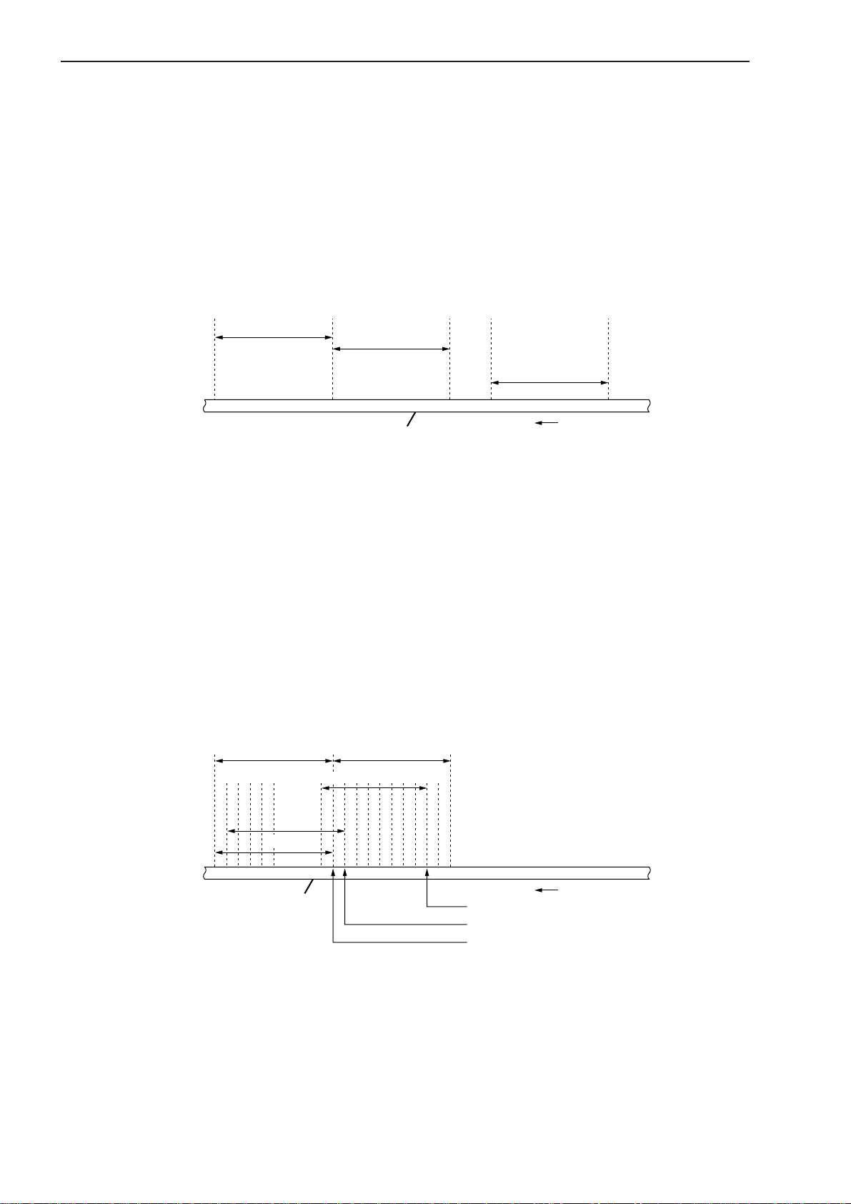
3.1.1.2 Setting the segment
Set the objective portion of a workpiece to be measured.
The highlighted and shaded portions created when the laser scans over the workpiece are
controlled with each assigned number. In the basic setup a selection must be made from one
of two cases: case where there are 1 to 4 highlighted and shaded sections, and case where
there are 1 to 127 similar sections. In the former case the portions are controlled through the
segment number, and are simply called segments. In the latter case the portions are controlled
by the edge number (edge number is between 1 and 255) and called edges. Edge numbers
equal to or greater than 256 are not available.
3. DISPLAYS AND KEY OPERATIONS
Segment specification
Highlight 1
Shade 1
Highlight 2
Shade 2
Highlight 3
Direction of laser scanning
Shade 3
Highlight 4
SEG1
SEG2
SEG3
SEG4
SEG5
SEG6
SEG7
• A maximum of 4 highlighted sections and a
maximum of 3 shaded sections can be measured.
• Multiple segments can be specified at the same
time.
• Specify segments 1 to 3 for a transparent object.
Edge specification
EDGE1
Highlight 1
Shade 1
Highlight 2
Shade 2
Highlight 127
Direction of laser scanning
Shade 127
Highlight 128
EDGE2
EDGE3
EDGE4
EDGE5
EDGE254
EDGE255
EDGE256
• A maximum of 127 highlighted sections and a
maximum of 127 shaded sections can be measured.
• Always specify the start edge and finish edge
numbers. These two edges can be either continued or separated. However, they must not be
identical.
• Edge numbers can not be specified for a transparent object.
• If automatic measurement is specified in the basic
setup, intervals, outside diameters, or gaps
between the same shape of multiple pins can be
automatically measured.
No. 99MBC095A
3 - 3
Page 25
3.1.1.3 Measurement interval (measurement time)
A measurement interval (measurement time) varies depending on the averaging method and
the number of scans selected for the measurement data.
There are two types of averaging method: the arithmetical average and the moving average.
Select the one best suited for the user’s purpose.
1) Arithmetical average
• If a moving workpiece is measured, the OD of the workpiece is determined by averaging
the measured data taken from each section (a: first measurement, b: second measurement,
.... n: nth measurement) of the workpiece the specified number of averaging times, as
shown below.
2) Moving average
first measurement
second measurement
ban
Moving workpiece
. . .
nth measurement
Moving direction
• One of the following number of averaging times can be selected: 1, 2, 4, 8, ....1024, 2048.
(If extra fine wire measurement is specified in the basic setup, the number of averaging
times can be selected from between 16 and 2048.)
• This is suitable for measuring a still object or the run-out of rollers, etc.
In the moving average method, a measurement interval identical to that in the arithmetical
average is divided into finer sections such as a1 (1st measurement), a2 (2nd measurement), -
- - , an (nth measurement). Each measurement is performed almost in parallel. If, for ex-
ample, the number of averaging times is set to 512, the first measurement requires the
amount of time that corresponds to 512 scans. However, for the second measurement onward,
only the time for 16 scannings is required. With respect to a workpiece with a changing OD,
this method provides data with smooth variation because of the many pieces of data, and also
quickly detects the trend of workpiece OD variation.
Measurement with
arithmetical averaging
Measurement with
arithmetical averaging
3 - 4
an
. . .
a2
a1
Moving workpiece
an measurement
. . .
a2 measurement
a1 measurement
Moving direction
Output of an measurement
Output of a2 measurement
Output of a1 measurement
• One of the following number of scans can be selected: 32, 64, 128, ....1024, 2048.
• This method is suitable for the feedback control of wire drawing machines and extruding
machines.
No. 99MBC095A
Page 26
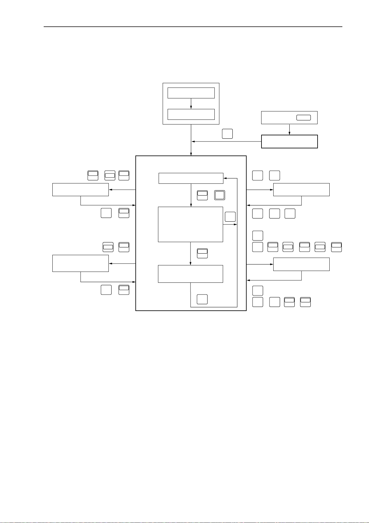
3.1.2 Outline of the Operation Modes
The LSM system has the following modes:
1: Basic setup mode, 2: Calibration mode, 3: Function setup mode, 4: Other setup mode, 5:
Statistical result display mode, and 6: Measurement mode.
3. DISPLAYS AND KEY OPERATIONS
Power ON
LOCK
4: Other setup mode
5 : Statistical result
display mode
Error check
SET
6 : Measurement mode
, ,
ENT
UNITUNIT
LOCK
( )
UNIT
Ready state
DATA C
,
RUN
Measurement in progress
(Program being executed)
C.RUN
C
LOCK
SHIFT
H.CAL L.CAL
ENT
• Single-run measurement
SHIFT
S.PR
PRINT
• Continuous-run
• measurement
( )
DATA C
RUN
SET
•
LIMIT
• , , + , +
Measured data display
(Latched display)
S.PR
SET
( )
PRINT
• Latch timer
C
•
SET
•
ENT
• ( , , )
Power ON +
SET
1 : Basic setup mode
2 : Calibration mode
( , )
H.CAL L.CAL
MASTER
REF
SHIFT
MASTER
REF
3 : Function setup mode
P.S V
MASTER
LIMIT
REF
P.SET
SHIFT
P.S V
P.SET
No. 99MBC095A
3 - 5
Page 27

3.1.2.1 Basic setup mode
• This mode is used to customize the basic setup conditions, including the resolution,
interface conditions, and available functions, according to the measurement requirements.
For more information, refer to Section 4.1, “Basic Setup”.
• To enter the basic setup mode turn on the power (turn the key switch clockwise from the
“O” position to the “I” position) while holding down the
key for about 2 seconds to initiate the basic setup mode.
3.1.2.2 Calibration mode
• Depending on the environment in which the LSM is used and the Display Unit - Measuring Unit combination, measurement errors may result. Therefore, always perform calibration prior to use, taking the measuring range and environmental conditions into account.
If calibration is performed, the errors described above will be reduced and high accuracy
will be ensured.
• Before performing calibration, always make the setups for resolution, simultaneousmeasurement, dual-unit measurement and available segments in the basic setup mode. If
this order is reverse, the previously set calibration values may be discarded.
• For more information, refer to Section 4.2, “Calibration”.
• Press the
key to enter the HI CAL mode; and press the
H.CAL
CAL mode.
3.1.2.3 Measuring condition setup mode
key. Hold down the
SET
key to enter the LOW
L.CAL
• This mode is used to set up measuring conditions, including segments (objective portion of
workpiece to be measured) and GO/NG judgment criteria.
• Press the
• Each of the
the individual function setup item to be established.
• Press the key to enter the setup operation for the setup item which is used most
often.
3.1.2.4 Other setup mode
• This mode is used to set the key lock and to set the unit of measurement.
• Press the
LOCK/
UNIT
• Press the
3.1.2.5 Statistic display mode
• Displays the statistical processing results.
• Press the
• Press the
results to be printed.
key to enable all the function setup items established to be set in a batch.
SET
LIMIT, SHIFT
and
SHIFT
LOCK/
→
P.S V/
key to turn on and off the key lock; and press only the
UNIT
P.SET
,
MASTER/REF
,
SHIFT
→
MASTER/REF
keys allows
key to enter the unit change mode.
SHIFT
SHIFT
SHIFT
and
and
and
key to enter the measuring position display mode.
READ
STAT/S.E
S.PR/
keys in the ready state to enter the statistic display mode.
keys in the ready state to allow the statistical processing
PRINT
3 - 6
No. 99MBC095A
Page 28

3.1.2.6 Measurement mode
This mode can be divided into the following operational states:
1) Measurement in the ready state
• This is the measurement mode that is entered immediately after the power is turned on
or if another measurement mode is aborted by pressing the
signal from the I/O interface or the “CL” command from the RS-232C/GP-IB interface).
• It is used to establish setups for calibration and available functions, which are not part
of the basic setup items, or to enter another measurement mode including single-run
measurement.
• Usually GO/NG judgment and analog output will not take place for measurement in the
ready state, however, these specifications can be made in the basic setup mode.
• Measurements in the ready state are unavailable for statistical processing.
2) Single-run measurement
• If the
the RS-232C/GP-IB interface) is pressed, one session of measurement is performed and
the results will be automatically subject to GO/NG judgment and analog output. In
addition, the measured data will be outputted for the RS-232C/GP-IB interface,
Digimatic Output Unit, and printer. The measured data will be held (latched for the
specified period) in the display.
• This data will be available for statistical processing.
DATA C/RUN
3. DISPLAYS AND KEY OPERATIONS
key (or by the RESET
C
key (otherwise input RUN via the I/O interface or “R” command via
3) Continuous-run measurement
• If the
key (otherwise input RUN+RESET via the I/O interface or “CR” command
C.RUN
via the RS-232C/GP-IB interface) is pressed, one session of measurement is started and
repeated the specified number of times. The measured data will be automatically subject
to GO/NG judgment and analog output. In addition, the measured data will be outputted
for the RS-232C/GP-IB interface, Digimatic Output Unit, and printer.
• Press the
DATA C/RUN
or
key (or if RUN is received from the I/O interface)
C.RUN
again to terminate the measurement and hold the measured data on the display. If the
key (or input RESET via the I/O interface or “CL” command via the RS-232C/GP-
C
IB interface) is pressed halfway, the measurement is aborted and the ready state is
returned to.
• The measurements are available for statistical processing.
4) Continuous measurement with a term specification
• This will take place where RUN input from the I/O interface has been assigned so as to
start a term-specified continuous-run measurement in the basic setup.
• Repeatedly performs single-run measurement while RUN signal input continues, which
is basically the same as the continuous-run measurement. Therefore, hereafter, continuous-run measurement includes the ones with a term specification.
• The measurements are available for statistical processing.
No. 99MBC095A
3 - 7
Page 29

5) Zero-run measurement
• A measurement where the number of samples is set to “0” is called a “zero-run measurement”.
• If the
DATA C/RUN
key (otherwise input RUN via the I/O interface or the “R” command
via the RS-232C/GP-IB interface) is pressed, single-run measurement is started and
repeated until the
DATA C/RUN
key is pressed again (or RUN is inputted via the I/O
interface or the “STOP” command is inputted via the RS-232C/GP-IB interface). From
the measured data the calculation items (mean, maximum value, minimum value, and
range) that have been set for the sample measurement will be calculated and the
resulting data will be automatically subject to GO/NG judgment and analog output. In
addition, the measured data will be outputted for the RS-232C/GP-IB interface,
Digimatic Output Unit, and printer. The measured data will be held on the display.
• The measured data are available for statistical processing.
• This is suitable for run-out measurement and cylindricity measurement.
6) Sample measurement
• A measurement where the number of samples is set to “2~999” is called a “sample
measurement”.
• In practice this will take place as a single-run measurement or a continuous-run measurement (with a term specification).
From the measured data the calculation items (mean, maximum value, minimum value,
and range) that have been set for the sample measurement will be calculated and the
resulting data will be automatically subject to GO/NG judgment and analog output. In
addition, the measured data will be outputted for the RS-232C/GP-IB interface,
Digimatic Output Unit, and printer.
• The measured data are available for statistical processing.
• This is suitable for run-out measurement and cylindricity measurement.
7) Statistical processing
• Measured data from single-run and continuous-run measurements can be statistically
processed (i.e. the number of measurement times, standard deviation, maximum value,
minimum value, mean, and range are calculated).
These statistical processing results can be outputted for the display, printer (statistical
memory for all programs will be cleared after printout), and RS-232C/GP-IB interface.
• Press the
STAT/S.E
key (or input “ST” command via the RS-232C/GP-IB interface) to
start statistical processing, and press it again (or input the “NST” command via the RS232C/GP-IB interface) to terminate statistical processing.
• Performs single-run measurements or continuous-run measurements to store statistical
data after statistical processing has been started.
• Pressing the
SHIFT
→
DATA C/RUN
, and
keys in this order will cancel the last
ENT
measurement.
• Pressing the
The item displayed will change each time the key
SHIFT
and
STAT/S.E
keys will display the results of statistical processing.
is pressed.
ENT
The display item will change in this sequence: [N: Measurement number], [S.D:
Standard deviation], [MAX: Maximum value], [MIN: Minimum value], [AVG: Mean
value], and [R: Range (Max - Min)].
Statistical processing will be performed independently for each program.
• Press the
A.CL/M.CL
(case of a simultaneous measurement), and press the
key to clear the statistical memory of the foreground program
SHIFT
and
A.CL/M.CL
keys to
clear the statistical memory of all the programs.
• These statistical results data will be stored in memory while the power is on, and will
be lost when the power is turned off.
3 - 8
No. 99MBC095A
Page 30
3. DISPLAYS AND KEY OPERATIONS
3.2 Techniques and Terminology of Setup Functions
3.2.1 Program
• A measurement will be automatically performed according to the registered (programmed)
contents including the segment (feature to be measured) and GO/NG judgment criteria,
etc., in advance. Registration is performed in the function setup mode.
• This unit can hold a maximum 100 programs, which may include various settings suitable
for up to hundred kinds of workpieces.
• Program numbers are divided into groups, each of which has up to ten programs and is
referred to as a channel (CH).
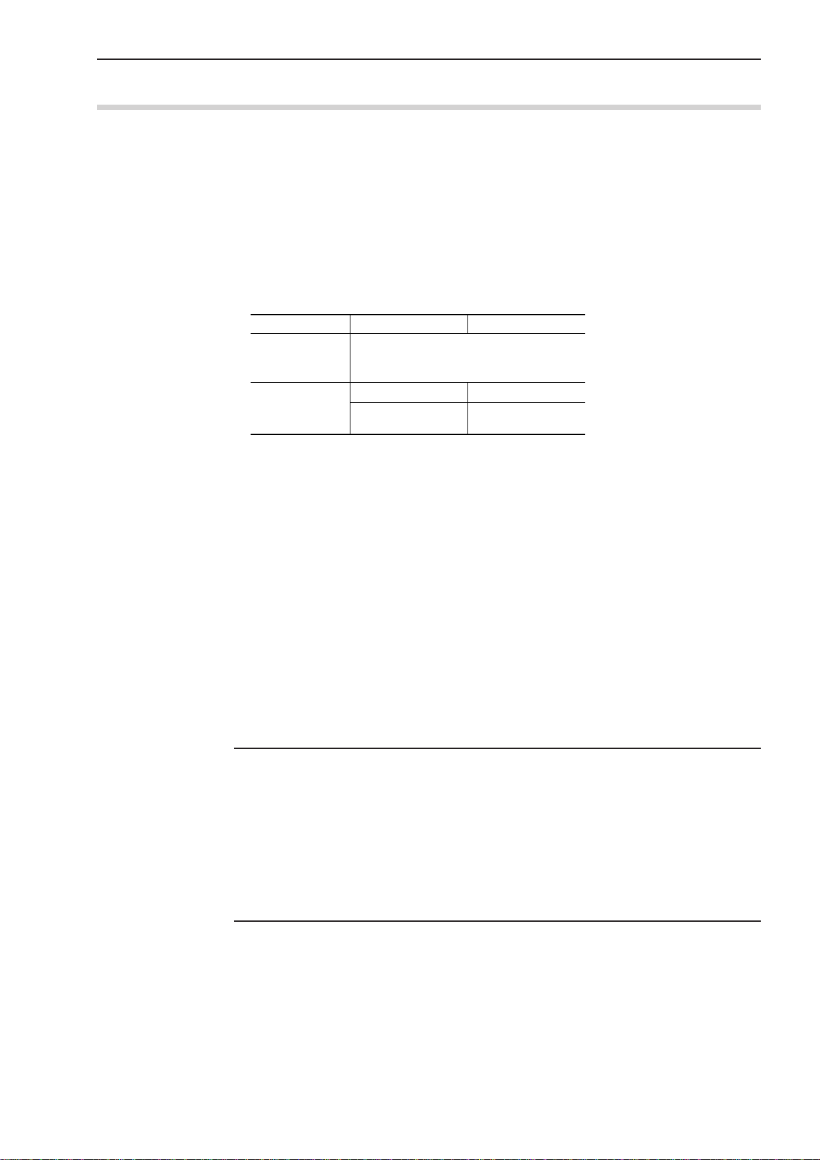
These two-digit program numbers define the meanings as shown in the table below.
Digit of ten
Program No.
Channel No.
Application
• As the expanded basic setup it is possible to select the range of applying calibration.
1. Applies uniformly to the entire 100 programs (factory default).
2. Applies individually to each channel (10 programs).
• With the expanded basic setup it is possible to select the range of applying presetting and
mastering.
1. Applies uniformly to the entire 100 programs (factory default).
2. Applies individually to each channel (10 programs).
3. Applies individually to each program.
• As the expanded basic setup it is possible to select either the “100 Program mode” or “10
program mode”, which limits the number of available programs to ten. (The factory
default setting is the 100 program mode.)
• As the basic setup it is possible to select either the “Single measurement mode” which
uses 100 programs (10 programs in the 10 program mode) as independent programs or the
“Simultaneous measurement mode” which uses two specific programs as a pair.
0 to 9
16
Digit of one
Individual No.
For each channel
0 to 9
No. 99MBC095A
NOTE • If the program must be switched to another with the RS-232C/GP-IB command, it
is necessary to use a separate command for the 100 program mode or 10 program mode.
For more information about the RS-232C/GP-IB command refer to Section 6.1.2.4
“RS-232C/GP-IB Commands”.
• In the 10 program mode the user can make use of the RS-232C/GP-IB commands
provided for Mitutoyo old models (LSM-6000, 6100) without further modification. It
is advised for the customers, who are operating Mitutoyo old models (LSM-6000,
6100) with the RS-232C communication commands, to use the 10 program mode.
3 - 9
Page 31

a) Single measurement
One session of measurement will be performed according to the one specified program.
The factory default setting is this single measurement.
b) Simultaneous measurement
• In one measurement session two specific programs are executed at one time as a pair.
Combinations of program numbers to form these pairs are shown in the following table.
• To run a pair of programs, either of the two can be specified via one of the numeric
keys and the one specified is called “foreground program”, and its counterpart is called
“background program”.
<<Possible combinations in the 100 program mode>>
Channel No. (Digit of ten of the program number) [0 to 4]
01234
00 & 05 10 & 15 20 & 25 30 & 35 40 & 45
Program
numbers pairs
Program
numbers pairs
01 & 06 11 & 16 21 & 26 31 & 36 41 & 46
02 & 07 12 & 17 22 & 27 32 & 37 42 & 47
03 & 08 13 & 18 23 & 28 33 & 38 43 & 48
04 & 09 14 & 19 24 & 29 34 & 39 44 & 49
Channel No. (Digit of ten of the program number) [5 to 9]
56789
50 & 55 60 & 65 70 & 75 80 & 85 90 & 95
51 & 56 61 & 66 71 & 76 81 & 86 91 & 96
52 & 57 62 & 67 72 & 77 82 & 87 92 & 97
53 & 58 63 & 68 73 & 78 83 & 88 93 & 98
54 & 59 64 & 69 74 & 79 84 & 89 94 & 99
3.2.2 Basic setup
<< Possible combinations in the 10 program mode>>
00 & 05
Program
numbers pairs
01 & 06
02 & 07
03 & 08
04 & 09
• This is used to customize the basic setup conditions, including the resolution, available
functions, and interface conditions, according to the measurement requirements.
• This basic setup must be performed at the beginning of a measurement. Note that changing
the setup of resolution, simultaneous measurement, or dual-unit measurement in this basic
setup cancel the existing calibration values and function setup.
• The basic setup mode is entered by turning on the power while holding down the
SET
key.
Note that no response will be made to an I/O interface input and RS-232C/GP-IB command in the basic setup mode.
• For more information, refer to Section 4.1, “Basic Setup”.
3 - 10
No. 99MBC095A
Page 32

3. DISPLAYS AND KEY OPERATIONS
3.2.3 Function setup
• Use this procedure to set up the conditions necessary for measurement.]
For each program number register measurement conditions including the segment (part
feature to be measured), measurement interval (measurement time), and GO/NG judgment
criteria that are the best suited for the objective workpiece.
• To enter the function setup mode press the
LIMIT, SHIFT
→
P.S V/
P.SET
,
MASTER/REF
setup item to be established, and the
SET
,
SHIFT
key enters the setup operation for items which
are most frequently accessed for set up.
• For more information refer to Section 4.5, “Setting Up the Functions”.
3.2.4 Setups according to the property of each workpiece
For measuring workpieces that transmit light or have a dimension smaller than the diameter
of the scanning beam it is critical to make setups that take into account the properties of the
workpiece.
3.2.4.1 Transparent object (Workpiece that transmits light)
a) Round bar
• Workpieces such as fiber optics and glass tubes are more or less transparent, while
workpieces made of steel are not. This requires different segment settings.
The segment settings for an opaque object and a transparent object are as follows:
• Setup for measurement of transparent or opaque object is possible in the basic setup.
key in the ready state. Each of the
→
MASTER/REF
keys allows the individual
Laser scan direction
Transparent
Workpiece
Photo-electric signal
For opaque object
Binary voltage (SHL)
Segment 1Segment 1
Segment 2
Segment 3 Segment 2
Segment 4
Segment 5 Segment 3
For transparent object
No. 99MBC095A
3 - 11
Page 33

b) Plate (Sheet)
W
Workpiece
Direction of light is turned,
and is not incidental to the
photo-electric element.
• In the case of the width measurement of a transparent plate with no chamfer on edges,
measurement may not be possible since acute-edge signals cannot be produced for such
edges.
Photo-electric signal
Laser scan direction
Transparent Workpiece
Measurement is aborted
Ideal edge signal
Binary voltage level (SHL)
because a sharp edge
can not be determined.
• For measuring a transparent plate-shaped workpiece
Take the following precautions:
1. Incline the workpiece.
By inclining the workpiece it is possible to attain a sharp edge from the light contrast. In this case:
Measurement : W = W0 (workpiece dimension) x cos θ
θ
W
2. Chamfering
Chamfer the workpiece edge by W. W will vary depending on the model. Always
use values larger than those in the table below.
Workpiece
0
ledomtinUgnirusaeMW:tnuomagnirefmahC
S005-MSLmm1.0
S105-MSLmm1.0
S305-MSLmm2.0
S605-MSLmm4.0
S215-MSLmm8.0
S615-MSLmm2.1
Direction of light is turned, and is not incidental to the photo-electric element.
W
3 - 12
No. 99MBC095A
Page 34

3. DISPLAYS AND KEY OPERATIONS
3. Changing the SHL
• With the reference workpiece set up on the Measuring Unit, connect the oscilloscope
to the [SCAN SIG.] terminal on the rear panel of the Display Unit and observe the
signal.
• SHL is the signal level for detecting a workpiece. Changing the level from the
standard level of 50% to a level such as 75% will enable the measurement of a
transparent sheet. The measurement accuracy, however, will be degraded since
measured data fluctuates according to the edge conditions of the sheet.
• It is possible to set the SHL level between 5% to 95% for "7 SHL" by setting up
"7 ADD"="USE" and "7 DLC"="OFF" in the expanded basic setup.
NOTE Measuring accuracy differs from that of the standard set up.
• Measured data differs with the change of the SHL. Perform calibration again if the
SHL setting has been changed.
• Measurement error can be reduced by performing calibration with the reference
standard, the edges of which have been made in the same condition as those of the
sheet to be measured.
Photo-electric signal
Laser scan direction
Transparent Workpiece
Standard SHL (50%)
New SHL: Set to 50 (1+v2/v1)%
v 1
v 2
v1: Peak voltage of photo-electric signal
v2: Larger voltage of the two at edges
(as generated at the edge with
better transmittance)
IMPORTANT • When the SHL (signal level for detecting a workpiece) is modified, the measure-
ment accuracy will be inevitably reduced, since the measured data may easily
fluctuate with the edge conditions.
• Once the SHL (signal level for detecting a workpiece) has been modified, always
perform another calibration.
• If an identical edge form is selected for both for the calibration standard and
workpiece (sheet), it may be possible to reduce these measurement errors.
No. 99MBC095A
3 - 13
Page 35

3.2.4.2 Ultra-fine wire measurement
• In the special ultra-fine wire measuring region, a clear shade can not be obtained because a
workpiece, with a finer diameter than that of the laser beam at the focal position, must be
measured. Therefore, this wire diameter must be calculated according to a special algorithm. This requires the following restrictions to be taken into account in the basic setup
where an ultra-fine wire measurement is designated.
a) Measuring interval (measurement time)
Note that the measurement time for the first measurement becomes 0.02 seconds longer
than the first interval since the wire diameter must be identified at the start of ultra-fine
wire measurement.
• Single-run measurement: (Measurement interval + 0.02 seconds)
• Continuous-run measurement: (Measurement interval + 0.02 seconds) for the first
b) Number of averaging times
Select a number between 16 and 2048.
c) Designation of the objective portion of workpiece to be measured
Only a segment specification is allowed, but an edge specification is not. If an edge
specification has been made before the setup for the ultra-fine wire measurement is
established, it is automatically changed to segment specification.
In other cases where multiple segments are set for the LSM-500S, the minimum
allowable measuring range begins at 0.1 mm. In addition, if a workpiece measures less
than 0.1 mm, only one segment can be specified.
d) Others
In extra-fine wire measurements, simultaneous measurement, dual measurement
(measurement using two measuring units), workpiece automatic detection, and group
judgment can not be set up. Setups for these functions are automatically canceled.
• The measuring position is a critical factor for ultra-fine wire measurement. Always
perform the measurement at the focal position of laser beam while referring to Section
5.2.2 “Displaying the measuring position”. In other cases where a fine gap is to be
measured, the amount of laser light may be insufficient, resulting in unstable measurements. Refer to Section 4.4, “Recording the Amount of Light”, and store the amount of
light without the workpiece and fixtures in the optical path.
• The following table shows the measuring ranges if “Not performing ultra-fine wire
measurement” is designated on the LSM-500S.
measurement, and at regular measurement intervals
for the second and subsequent measurements.
3 - 14
egnargnirusaeM
0S05-MSLmm2ot500.0mm2ot1.0
)yrotcafehtta(
egnargnirusaemdradnatS
fiegnargnirusaeM “ eriwenif-artlugnimrofreptoN
tnemerusaem ” detangisedsi
• The ultra-fine wire measurement function is only available on the LSM-500S.
No. 99MBC095A
Page 36

3. DISPLAYS AND KEY OPERATIONS
IMPORTANT 1. For measuring ultra fine wire with a diameter thinner than that of the laser beam,
the SHL (signal level for detecting a workpiece) needs to be changed according to
the workpiece size (external diameter).
2. Since the SHL is changed to the level most appropriate for the workpiece size,
multiple workpieces or workpiece fixtures existing within the laser scanning range
may disable the detection of a workpiece less than 0.05 mm in diameter. Exercise
care so as not to produce multiple shadows within the scanning range.
3. Also, if the segment is set to 1 or 3, it is not possible to determine the position of
a fine workpiece less than 0.05 mm in diameter, runout, and bending.
No. 99MBC095A
3 - 15
Page 37

3.2.5 Measurement of an odd-numbered-edge cutting tool
• This function is used to measure the diameter or run-out of cutting tool (drill or end mills,
etc.)that has an odd number (3, 5, ...) of cutting edges.
• When the outside diameter, øD, of an odd-numbered-edge cutting tool is measured, the
measurement errors as shown in the figure below will result if this LSM unit is set to
Segment 2 (normal outside diameter measurement) for measurement.
To avoid these errors, in this case, first install the reference bar as shown below, then
perform the measurement while rotating the odd-numbered-edge cutting tool. Calculate the
outside diameter of the odd-numbered-edge cutting tool by obtaining the difference
between “Peak value of Segment 2+3” and “Bottom value of Segment 3” while the cutting
tool rotates more than one turns from the beginning of measurement.
Then save the bottom value of Segment 3 into memory as many as the number of cutting
edges being set, and calculate the range (maximum - minimum) as the “run-out”.
Odd-numbered-edge cutting tool
Segment 2
Error
Segment 3
(minimum value)
øD
Segment 2+3
Reference bar
(maximum value)
• For the measurement examples and setup method refer to Section 5.3.6 “Application of the
odd-numbered-edge cutting tool measurement”.
TIP • As shown in the figure at the right it is also possible to measure with the reference
bar being located in the Segment 1 side.
In this case the “outside diameter”
of the odd-numbered-edge cutting
tool can be calculated by obtaining
the difference between “Peak value
of Segment 1+2” and “Bottom value
Odd-numbered-edge
cutting tool
(minimum value)
Reference bar
Segment 1
of Segment +1” while the cutting
tool rotates more than one turns
from the beginning of measurement.
Segment 2
øD
Segment 1+2
(maximum value)
Also, the “run-out” can be calculated by saving the bottom value of
Segment 1 into memory as many
Error
as the number of cutting edges
being set to Segment 1, and calculate the range (maximum - minimum).
• It is necessary to select, in the basic setup, whether the reference bar is located in
the Segment 1 side or in the Segment 3 side.
3 - 16
No. 99MBC095A
Page 38

3. DISPLAYS AND KEY OPERATIONS
3.2.6 Measurement with two Measuring Units (dual-unit measurement)
• The LSM-500S series Measuring Unit allows measurement to be performed with two
Measuring Units, if the optional dual-type add-on unit is provided.
To use two Measuring Units they must be the same model.
• About Measuring Unit 1 which is connected to “TRANSMITTER-1” side, and Measuring
Unit 2 which is connected to “TRANSMITTER-2” side
a) The W.P. (Work Position) LED shows the workpiece position of the Measuring Unit 1
when the least significant digit of program number between 0 and 4 is specified, and
that of the Measuring Unit 2 when the least significant digit of program number
between 5 and 9 is specified.
b) Select he least significant digit of program number between 0 and 4 to calibrate
Measuring Unit 1, and between 5 and 9 to calibrate Measuring Unit 2.
LSM-6100 Display unit
Measuring unit 2
Least significant digit of program number: 5 - 9
“TRANSMITTER-2”
Measuring unit 1
Least significant digit of program number: 0 - 4
“TRANSMITTER-1”
• If the dual-type add-on unit is mounted, select the type of dual-unit measurement in the
basic setup.
Note that if the type of dual-unit measurement is changed in the basic setup, calibration
values and function setups will be default-set.
• If the dual-type add-on unit is not set, the setup guidance for it will not be displayed.
• Suspended use of Measuring Unit
For repair or adjustment services one of the Measuring Units employed for dual-unit
measurement may be suspended from operation. If this is the case, turn off the power and
disconnect the Measuring Unit. If the Measuring Unit 1 has been disconnected, the
Measuring Unit 2 must be connected to the TRANSMITTER-1 while re-installing the
corresponding ID unit in place. After removal of one measuring unit, designate
in the basic setup (4.1.2.3 Selecting an setting the function in the B2 mode: d. Setting the
dual-unit measurement).
If one Measuring Unit is removed without this designation, “Err-8” will result and the
other Measuring Unit will also become inoperable.
Note that suspending one Measuring Unit will cause the calibration values and function
setups to be reset to their defaults.
• The type of dual-unit measurement includes DW-, DXY-, and DF-types.
No. 99MBC095A
3 - 17
Page 39

3.2.6.1 DW type
• This setting is used if two workpieces are measured by two measuring units set in parallel.
• On each of the Measuring Units 1 and 2 the measuring position can be selected from
segments 1 to 7 (1 to 3 for measuring a transparent object) or edges 1 to 255.
SEG
1
2
3
4
5
6
7
Measuring unit 2
Display unit
Least significant digit of
program number: 5 - 9
SEG
1
3
5
7
2
4
6
Measuring unit 1
Least significant digit of
program number: 0 - 4
• Calibration
Select each segment for Measuring Unit 1 with the least significant digit of program
number between 0 and 4, and select each segment for Measuring Unit 2 with the least
significant digit of program number between 5 and 9.
3 - 18
No. 99MBC095A
Page 40

3.2.6.2 DXY type
3. DISPLAYS AND KEY OPERATIONS
• Used to perform X-Y (2-axis) measurement with two Measuring Units positioned perpendicular to each other.
• For DXY-type measurement the objective portion of the workpiece to be measured should
be selected through segment specification, not by edge specification.
Select segments 1 to 3 for Measuring Unit 1, and select segments 5 to 7 for Measuring
Unit 2.
SEG 1
SEG 2
SEG 3
SEG 5
Measuring unit 2
(Y-axis direction)
SEG 6
SEG 7
Measuring unit 1
(X-axis direction)
Display unit
Least significant digit of
program number: 0 - 4
Least significant digit of
program number: 5 - 9
• Calibration
Select each segment (between 1 and 3) for Measuring Unit 1 with the least significant
digit of program number between 0 and 4, and select each segment (between 5 and 7) for
Measuring Unit 2 with the least significant digit of program number between 5 and 9.
• Any program number can be assigned to segments 1 to 3 (in the X direction) and segments
5 to 7 (in the Y direction).
• If one segment for each of the X and Y directions are selected (e.g. 2 + 6), calculation is
made possible between the measurements from these segments in the X and Y directions.
The calculation items can be selected in the basic setup by arithmetic addition: (X + Y),
mean outside diameter: (X + Y) / 2, Difference: (X-Y), and film thickness: (X-Y) /2.
No. 99MBC095A
3 - 19
Page 41

3.2.6.3 DF type
• Used to measure the diameter of a large workpiece using two Measuring Units facing each
other, one stacked on top of the other, or positioned back to back.
• For DF-type measurement the objective portion of the workpiece to be measured should be
selected through segment specification, not by edge specification.
Select segments 1 to 3 for Measuring Unit 1, and select segments 5 to 7 for Measuring
Unit 2.
Display unit
SEG 5
Measuring unit 2
Least significant digit of
program number: 5 - 9
SEG 1
SEG 7
SEG 6
SEG 5
SEG 1
SEG 2
SEG 3
Measuring unit 1
Measuring unit 2
Measuring unit 1
a) Example of units facing each other
SEG 5
SEG 1
EG 5
EG 6
EG 7
Measuring unit 2
Measuring unit 1
Measuring unit 2
Least significant digit of
program number: 0 - 4
Least significant digit of
program number: 5 - 9
Least significant digit of
program number: 0 - 4
Display unit
Least significant digit of
program number: 5 - 9
Least significant digit of
program number: 0 - 4
Least significant digit of
program number: 5 - 9
3 - 20
EG 1
EG 2
EG 3
b) Example of stacked units
Measuring unit 1
Least significant digit of
program number: 0 - 4
No. 99MBC095A
Page 42

SEG 5
Measuring unit 2
3. DISPLAYS AND KEY OPERATIONS
Display unit
Least significant digit of
program number: 5 - 9
Least significant digit of
program number: 0 - 4
Least significant digit of
program number: 5 - 9
Least significant digit of
program number: 0 - 4
EG 7
EG 6
EG 5
EG 3
EG 2
EG 1
SEG 1
Measuring unit 1
Measuring unit 2
Measuring unit 1
c) Example of units positioned back to back
• Position two Measuring Units back to back as shown in 3) above to measure a transparent
object with the DF-type setup.
Transparent objects may not be measured with units facing each other or stacked one on
top of another.
• For information about techniques to improve the measuring accuracy refer to the measuring unit user’s manual.
• Calibration and combined offset
a) Separate calibration for each Measuring Unit
Perform the calibration after selecting Segment (1 ~ 3) at the Measuring Unit 1 side
with the least significant digit of program number set to between 0 and 4 for Measuring
Unit 1, and Segment (5 ~ 7) at the Measuring Unit 1 side with the least significant digit
of program number set to between 5 and 9 for Measuring Unit 2, respectively.
b) Combined calibration
In addition to being able to perform separate calibration for each Measuring Unit, the
DF-type setup allows the use of combined calibration where segments are assigned over
two Measuring Units.
This combined calibration is effected from either combination of segments (1 + 5) or (1
+ 7).
Note that cancellation of separate calibration will also cancel the combined calibration.
IMPORTANT Since the reflection light from a large-diameter workpiece (skip phenomenon) is
generated in DF-type measurement, the accuracy decreases to some extent, compared with the linearity of each measuring unit. The following figure shows that
undesired values e1 and e2 are generated due to reflected light. The undesired
value (e1, e2) increases with the diameter of the workpiece (e2 > e1). This depends
on the reflectivity of the surface.
Therefore, if each measuring unit is calibrated independently using a small diameter
gage, an error may result if a large diameter is measured.
No. 99MBC095A
3 - 21
Page 43

Reception lens
e1
Workpiece
e2
Workpiece
θ
S
Photoelectric device
(a) Measuring a small diameter workpiece
Reception lens
θ
S
(b) Measuring a large diameter workpiece
If a large-sized workpiece is measured using the DF-type setup, combined calibration
will ensure more accurate measurment.
c) Combined preset
While combined calibration is used to measure workpieces of various sizes, the combined preset is used to measure workpieces with a dimension close to the reference
gauge.
Since, at a combined preset, separate values can be set for each program number, a
maximum of 100 kinds of workpieces can be registered. To perform the combined
preset make the measuring positions of the reference gauge and workpiece as consistent
as possible.
Designate the combined preset by combining segments such as (1 + 5) or (1 + 7), and
set the direction to negative (1).
However, if this is coupled with a combined calibration, set the direction to positive (0).
3.2.7 Latch (holding) of the displayed value
• In a single-run measurement, etc., GO/NG judgment and analog output will be continued
while the measured data is latched (held) on the display for the specified period of time.
After the set period elapses, system operation returns to the ready state.
• Set up the display latch timer in the basic setup.
• While the display is being latched, inputs from the I/O interface or RS-232C/GP-IB are
still valid.
3 - 22
No. 99MBC095A
Page 44

3. DISPLAYS AND KEY OPERATIONS
3.2.8 Automatic measurement with an edge specification
• If the edge specification is made, it is possible to automatically measure IC or connector
leads with respect to their pitch (even intervals), outside diameter, or gap. This is suitable
for inspecting the IC lead bend, etc.
Outside
diameter
Gap
Laser
scanning
direction
Pitch
• This function is only in effect if the necessary setups are made for edge specification in
the basic setup.
• In the function setup designate whether automatic measurement should be performed (for
pitch/outside diameter/gap measurement) or not (manual measurement). Also designate
both the start and finish edges.
• This is available in combination with automatic workpiece detection.
• If automatic measurement has also been selected, the following will take place.
a) In the ready state the first objective portion of the workpiece to be measured will be
displayed.
No. 99MBC095A
b) Automatic measurement will be involved in a single-run measurement or continuous-
run measurement.
If “Err-0” (insufficient number of edges to be measured) is detected, the measuring
operation is stopped for the single-run measurement, and the collected measured data is
cleared for continuous measurement to wait for a proper workpiece to be loaded.
c) If the measured data is found to be ±NG, the first source of the ±NG will be displayed
and the measuring operation is stopped. If GO results, the mean of all measurements is
displayed.
d) If the measured data falls within the range of GO, the elapsed measurement time was as
follows:
(Number of measurement edges) x (measurement interval) + (calculation time: 20 ms)
e) The W.P. LED shows the current portion of the workpiece being measured.
3 - 23
Page 45

3.2.9 GO/NG judgment
• All the measured data are subject to GO/NG judgment.
To enable, set the GO/NG judgment criteria in advance.
• The following settings can be made in the basic setup.
a) The method of tolerance judgment can be selected from (Lower limit value and upper
limit value), multi-limit selection (7 limits) and (Target value and tolerance values:
upper tolerance value and lower tolerance value).
To output the judgment result with the multi-limit selection it is necessary to select the
optional Second Analog I/O Interface.
b) Simultaneous measurement can be specified. To do this, it is necessary to select the
optional Second Analog I/O Interface for tolerance result output.
c) For (Target value and tolerance values), the user is permitted to select whether the
target value is to be copied to the reference value. If it is, the setup guidance for the
reference value will not appear.
d) Even in the ready state it is possible to select whether tolerance judgment and analog
output are performed. If they are, tolerance judgment and analog output will take place
in the ready state, however, these data are not available for statistical processing.
e) Abnormal data elimination, tolerance judgment, group judgment, and analog output can
be performed in a single-run measurement, zero-run measurement, sample measurement, and continuous-run measurement (with a term specification). The judgment result
will be indicated by the -NG (red LED), GO (green LED), and +NG (red LED) indicators and outputted to the I/O interface and RS-232C (including printer)/GP-IB interface.
f) The following tables show the relationship between the measured data and tolerance
judgment method
1) (Lower and upper limit values)
tnemgdujGN/OG )teseraseulavtimilreppudnarewolehthtobfidegduj(tnemerusaeM
GN-eulavtimilrewoL<tnemerusaeM
OGeulavtimilrewoL ≤ eulavtimilreppU<tnemerusaeM
GN+tnemerusaeM ≥ eulavtimilreppU
2) (Target value and tolerance values)
tnemgdujGN/OG
GN-)timilecnarelotrewol+eulavtegraT(<tnemerusaeM
OG
GN+tnemerusaeM ≥ )eulavecnarelotreppu+eulavtegraT(
)eulavecnarelot
)teseraeulavecnarelot
)eulavecnarelotrewol+eulavtegraT( ≤ reppu+eulavtegraT(<tnemerusaeM
reppudnaeulavecnarelotrewol,eulavtegratehtfidegduj(tnemerusaeM
3 - 24
No. 99MBC095A
Page 46

3. DISPLAYS AND KEY OPERATIONS
3) If all limits from L1 to L6 are set for multi-limit selection
tuptuonoitcelestimil-itluMtnemgdujGN/OG.tesera6Lot1LmorftnemerusaeM
1LGN-1L<tnemerusaeM
2LOG1L ≤ 2L<tnemerusaeM
3LOG2L ≤ 3L<tnemerusaeM
4LOG3L ≤ 4L<tnemerusaeM
5LOG4L ≤ 5L<tnemerusaeM
6LOG5L ≤ 6L<tnemerusaeM
7LGN+6L ≤ tnemerusaeM
4) If only L1 and L2 are set for multi-limit selection
tuptuonoitcelestimil-itluMtnemgdujGN/OG
1LGN-1L<tnemerusaeM
2LOG1L ≤ 2L<tnemerusaeM
7L~3LGN+2L ≤ tnemerusaeM
.tesera2Ldna1LylnOtnemerusaeM
enoylnofidemrofrepebtonlliwtnemgduJ(
).tessiegats
No. 99MBC095A
3 - 25
Page 47

3.2.10 Abnormal data elimination
• The abnormal data elimination function eliminates measurements that are very different
from those specified for the machined workpiece, from the measurement data (neither the
measurement is displayed nor is data output performed).
If, for example, the grindstone of a centerless grinder is controlled based on the measured
data from the LSM, it is possible that a large measurement error may be created due to the
coolant used with the workpiece.
As shown in the figure below where foreign matter (with a height of h) adheres to within
the averaging region L of the workpiece (with a diameter of D). An abnormal outside
diameter results in the region of l and the displayed measurement will be (D + lh / L). As
the result the grinder is subject to improper control that involves some error.
Because the use of this function can eliminate abnormal measurement data generated due
to the adhered foreign matter, the grindstone can be controlled and fed properly.
L
l
D Workpiece
Workpiece feed direction
h
• Judgment of valid data or abnormal data will be performed at each measurement interval.
Valid data includes those satisfy the following relation: Lower abnormal limit ≤ (Measurement) < Upper abnormal limit. All other data will be discarded as abnormal data.
• The following table shows the relationship between measurements and upper and lower
abnormal limits.
etanimiletonoD/etanimilE
etanimilEtimillamronbarewoL<tnemerusaeM
etanimiletonoD
etanimilEtnemerusaeM ≥ timillamronbareppU
)tnemerusaemasadetpecca(
timillamronba
).teserastimillamronba
timillamronbarewoL ≤ reppU<tnemerusaeM
rewoldnareppuehthtobfidegduJ(tnemerusaeM
• In the basic setup select whether this abnormal data elimination function should be used. If
it is the setting of (lower abnormal limit, upper abnormal limit, and count value) should be
performed before actual tolerance judgment.
This count value indicates the number of pieces of abnormal data that occurred until the
alarm will be issued. This alarm output will be sent to the optional Second Analog I/O
Interface by CNT form (The alarm will not be issued if the count value is set to zero).
• Abnormal data elimination function effects in single-run and continuous-run measurements.
• If “Err-0” (specified workpiece not present) is displayed in the sample measurement, the
valid data collected will be discarded.
3 - 26
NOTE If a long series of abnormal data appears, measurement can no longer be continued
since most of the measured data must be eliminated. To avoid this problem, always
monitor CNT output.
No. 99MBC095A
Page 48

3.2.11 Preset/Zero-set
p
This function is used to measure the difference between the workpiece and the reference gage
or to measure the workpiece that is larger than the measuring range of the LSM.
a) Preset
b) Zero-set
c) Direction
3. DISPLAYS AND KEY OPERATIONS
• In this system the operation of setting the reference gage dimension is called the
preset operation.
• This function is applied to measure the absolute dimension of a workpiece.
• Setting the reference gage dimension to “0.0” for the purpose of comparing it with a
workpiece dimension is called the zero-set.
• This function is applied to measure a deviation from the reference gage dimension.
Depending on the objective portion of measurement of a workpiece, the positive
direction (set as “0”) or negative direction (set as “1”) must be set.
If, for example, the shaded portion of D in the following diagram is measured, the
direction must be set as positive (0). If the highlighted portion (gap) of W is to be
measured for determining the workpiece dimension L, the direction must be specified
as negative (1).
Set as positive (0) Set as negative (1)
3.2.12 Mastering
Reference piece
W
Workpiece
D
Workpiece
Reference
L
lane
• Preset operation takes about 1 second to determine the compensation value by measuring
the reference gage.
• Preset value will be ineffective if the segment or edge number is changed (Preset value is
unique to each segment or edge).
• If the objective workpieces are high-precision gages that are machined successively, the
above described preset/zero-set values may need to be fine-adjusted to the master. This
fine-adjustment is called mastering.
After mastering, the total compensation value will be:
(Preset value/zero-set value) + (±Mastering value)
Setting a positive (+) mastering value allows the measurement of a workpiece OD to be
greater than the raw measurement, and setting a negative (-) mastering value allows the
measurement of a workpiece OD to be smaller than the raw measurement.
No. 99MBC095A
• Because no measurement is required for this mastering, the reference gauge is not required
either.
• Set the reference gage dimension with the preset function and perform mastering.
3 - 27
Page 49

3.2.13 Reference value
• This function is used to output deviations (measured data - reference value) between the
reference value and the actual measurements of a workpiece for the Analog I/O Interface.
Before analog output, set the reference value and the scale value (gain).
• Measured data is outputted as analog signals at a full scale of ±5V.
Analog signal = (Measured data - reference value) x scale value (gain)
• In the basic setup the following conditions can be set.
a) Whether the target value of GO/NG judgment is be copied to the reference value. If this
is selected, the setup guidance for the reference value will not be displayed, so only the
scale value must be set.
b) It is also possible to set so that tolerance judgment and analog output can take place in
the ready state.
• Analog output is automatically enabled if single-run measurement or continuous-run
measurement is performed.
• If the reference value is being set the deviation value will be output for the RS-232C/GPIB interface and the printer if single-run measurement or continuous-run measurement is
performed.
3.2.14 Data output conditions
• In single-run measurement or continuous-run measurement, measured data can be outputted for each measurement if ±NG occurs, or at given intervals to the RS-232C/GP-IB
interface, printer, or Mitutoyo Digimatic Output Unit.
Data output condition Printer
0
1
2
4
6
7
8
9
: Outputted for each measurement if or key, etc., is pressed.
: Press the or key to trigger the measurement. The measured data will be outputted if it falls on GO.
: Press the or key to trigger the measurement. The measured data will be outputted if it falls on –NG.
: No output will be made.
DATA C/RUN
DATA C/RUN
RS-232C
GP-IB
DCU
C.RUN
C.RUN
DATA C/RUN
Remark
The periodical output timer can be set
The periodical output timer can be set3
The periodical output timer can be set5
C.RUN
3 - 28
No. 99MBC095A
Page 50

3. DISPLAYS AND KEY OPERATIONS
No workpiece
detected
Start of
measurement
Detection of
workpiece
Invalidation
elapses
Measured the specified
number to times
3.2.15 Automatic workpiece detection <OD detection method, Position detection method>
• Automatic workpiece detection is performed for continuous-run measurement, where
measurement starts with no specified workpiece present (Err-0), then proceeds to automatic detection of the workpiece, followed by measurement repeated number of times. No
specified workpiece present (Err-5) also refers to the workpiece outside the upper and
lower detection limits.
• Whether automatic workpiece detection is performed is specified in the basic setup mode.
If automatic workpiece detection is specified, the number of scanning times for detection
must be specified from among 1 and 16. Select 16 times if detecting precision workpieces.
If automatic workpiece detection is not specified, no further setting is necessary.
• Automatic workpiece detection setup includes the number of measurement times, invalidation period, upper and lower detection limits. Set both the upper and lower detection
limits.
• To exclude the measured data of such as chamfered portion of the workpiece, invalidation
period can be set within the range from 0.001 sec to 9.999 sec.
1) OD detection method
• This is used to automatically detect a workpiece that enters the laser scanning plane
perpendicularly.
• For actual detection of a workpiece the displayed measurement (after calibration and
preset) is used.
• One session of automatic detection consists of no workpiece being detected, detection of a workpiece with a dimension that is within the detection range (between the
upper and lower detection limits), an invalidation period required to exclude invalid
dimensions (of chamfered portions, etc.) from the measurement, and effective
measurement for the specified number of times. The final measurement result will be
latched (held) on the display. Once entering the effective measurement the upper and
lower detection limits will no longer be checked.
• The speed of workpiece detection (i.e. the number of scans) can be specified as
either 1 or 16 in the basic setup.
• Use 16 times in the following cases:
* If connecting bars are used between workpieces for feeding convenience and for
setting appropriate intervals between workpieces, and, if the difference in the
outside diameter between the workpiece and the bar is insufficient.
* If the feed rate is low.
• The following diagram is an example where a workpiece with a chamfered outside
diameter of D mm and a length of ᐉ mm moves at a velocity of V mm/s.
c
ᐉ
g
Scanning beam
No. 99MBC095A
D
a
Workpiece flow V mm/s
3 - 29
Page 51

Setting example:
• Lower detection limit: L < (a +D) / 2
• Upper detection limit: H > Upper limit of the measuring range or 1.1 D
(This setting may be omitted.)
• Invalidation period : T > (c / V) ms
•
Number of measurements: N < (ᐉ - 2c) x 0.8 (safety factor) / measurement interval / V
2) Position detection method
• This is used to automatically detect a workpiece that enters the measuring region in
the laser scanning plane in the same direction of the scan.
• Workpiece detection is performed with one scan, and 16 scans can not be specified
(If specified in the basic setup, the specification will be ignored).
• One session of automatic detection consists of the detection of no workpiece,
detection of a workpiece edge with a dimension that falls within the detection range
(between the upper and lower detection limits), an invalidation period required to
exclude invalid dimensions from the measurement, and effective measurement for the
specified number of times. Once the effective measurement has been entered, the
upper and lower detection limits will no longer be checked.
• In the following diagram, workpiece positions (a) and (b) result in no workpiece
being present, and in (c) it is judged that a workpiece is present.
Detected edge
L
H
C
Vmm/S
(a)
(b)
(c)
Laser scanning range
Measuring region
L : Lower detection limit
H : Upper detection limit
C : Detection range
Laser Scanning direction
Setting example:
Assuming the workpiece diameter as D (mm) and the moving speed as V (mm/s):
• Lower detection limit: L > (Laser scanning range - measuring region) / 2
• Upper detection limit: H < (Laser scanning range + measuring region ) / 2 - D (This
setting may be omitted.)
• Invalidation period : Generally set to 0 ms.
• Number of measurements: N = 1
NOTE • Allow a sufficient margin for the lower detection limit, upper detection limit, invali-
dation period, and number of measuring times when setting them. If this surplus is
not sufficient, the measurement may not be achieved.
• If using the sample measurement, specify the number of measuring times to 1.
• The automatic workpiece detection functions in the continuous-run measurement.
3 - 30
No. 99MBC095A
Page 52

3.2.16 Group judgment
Output of
judgment
result 1
Output of
judgment
result 2
Output of
judgment
result 3
Output of judgment result 1
Output of
judgment result 2
Output of
judgment
result 4
Output of
judgment
result 5
Output of
judgment
result 6
Output of
judgment
result 7
Judgment to Group 1 Judgment to Group 2 Judgment to Group 3
Output of group judgment result
Individual
judgment
1
Individual
judgment
2
Individual
judgment
3
Individual
judgment
4
Individual
judgment
5
Individual
judgment
6
Individual
judgment
7
Individual
judgment
8
Output of individual
judgment result
• While the tolerance judgment is applied to each measurement from a workpiece, this group
judgment is applied to a group of the specified number of workpieces.
• In the basic setup select whether group judgment is to be performed. If it is, then set the
group size (the number of workpieces included in a group), calculation items (mean,
maximum value, minimum value, and range), and group lower limit and upper limit. If
“Not performing group judgment” is selected, the setup guidance for it will not be displayed.
• The group judgment will be in effect in a single-run measurement or continuous-run
measurement.
a) For the result display and GO/NG judgment indication each individual measurement
b) Output of judgment result
c) RS-232C/GP-IB output
3. DISPLAYS AND KEY OPERATIONS
and judgment result will be used.
1. If only the standard Analog I/O Interface is used
Each individual judgment result will be outputted.
2. If the second Analog I/O Interface is used
Each individual judgment result will be outputted for A-(+NG), A-(GO), and A-(NG), and the group judgment result will be outputted for B-(+NG), B-(GO), and B-(NG), respectively.
In the basic setup it is possible to set whether the group judgment result data is outputted for the RS-232C/GP-IB interface. If it is, the output contents from the group
judgment will be as follows:
No. 99MBC095A
P0, ( GO) 12.34567 ... Individual data
P0, ( GO) 12.34560 ... Individual data
P0, (+NG) 12.34600 ... Individual data
GP0, ( GO) 12.34575 ... Group judgment result data
• Each individual piece of measurement data can be the objective of statistical processing,
however, group measurement data will be excluded from statistical processing.
• Even if “Err-0” (specified workpiece not present) occurs, the obtained data will not be
cleared. To abort the measurement, press the
key (or input RESET via the I/O
C
Interface or the “CL” command via the RS-232C/GP-IB interface).
3 - 31
Page 53

3.2.17 Recording the amount of light
• The gap measurement may be unstable if not enough laser beam passes through the gaps.
In the case shown in diagram (a) below, an adequate amount of light can be obtained as
the laser passes through gap (g) above the workpiece, even if the gap (t) is small. However, in diagram (b) where gap (t) is small, measurement will be affected. In this case,
therefore, it is necessary to have the system record the full amount of light when there is
no obstruction (workpiece or fixture) in the optical path.
Laser beam
passes through
this gap.
Photo-electric signal
Light amount
can be detected
Peak of the
photo-electric
signal
Light amount
cannot be detected
(insufficient duration)
Workpiece
Workpiece
g: Gap for the
reference beam
t
Gap
(a) Light amount can be detected normally = Auto-detecting
t
Gap
(b) Recording the amount of light is required
• Normally the amount of incident light is continuously checked so that the counting
operation can follow the change in the amount of incident light. Have the system record
the light amount following 4.4, “Recording the light amount”. It is also necessary to carry
out this operation twice or three times each year since the light amount of the system may
vary.
• If the amount of light is recorded, temperature drift of the measured data becomes larger.
• The minimum size of gap (t) that can be measured depends on each Measuring Unit as
shown below:
3 - 32
emanledoMtrog:paG
S005-MSLeromromm2.0
S105-MSLeromromm3.0
S305-MSLeromromm1
S605-MSLeromromm2
S215-MSLeromromm4
S615-MSLeromromm6
No. 99MBC095A
Page 54

3. DISPLAYS AND KEY OPERATIONS
3.3 Outline of the Display Contents
Displays of this system are effected by the display unit and guidance LEDs.
3.3.1 Display unit
The name of each part of the display unit and the LEDs are given below:
Data display unit (fluorescent display tube)
PROG
LOCK DUALP.SETCAL S.E
Upper display section
Lower display section
Measurement state guidance
3.3.2 Data display unit
1) Numeric and character display
LD1 ON
LD2 ON
-NG
GO
+NG
RUN
BUSY
BUSY LED
RUN LED
GO/NG judgment LEDs
LD oscillation LED
W.P. (Work Position) LED
• Single measurement: Turns off.
• Simultaneous measurement:
Displays a background program number.
• Displays a settting item in the single measurement.
• Single measurement: Displays a setup value.
• Simultaneous measurement:
Displays the measured data of a background program.
• Displays the unit of measurement.
• Displays the measured
data of a foreground program.
• Displays a foreground program number.
No. 99MBC095A
2) Operation state guidance
• LOCK: Turns on in the key lock state, which is initiated by pressing both the
and
LOCK/
keys. If these keys are input the key lock state will be can-
UNIT
celed.
• CAL: Turns on if the calibration (HIGH) is specified.
• P.SET: Turns on if the preset function is active.
• S.E: Turns on if statistical processing is activated.
• DUAL: Turns on if simultaneous measurement is specified.
SHIFT
3 - 33
Page 55

3) Display LED
• W.P. (Work Position) LED
LED segments corresponding to a region shaded by the workpiece, which blocks the
laser beam, will turn off. This is used to check if the workpiece is located in the center
of the measuring region.
• LD oscillation LED
1. LD1 ON : Indicates that the laser in the Measuring Unit connected to the
“TRANSMITTER-1” connector is oscillating. If a dual-unit measurement is not
performed (standard specification), only this LED lights and the LD2 LED is off.
2. LD2 ON : Indicates that the laser in the Measuring Unit connected to the
“TRANSMITTER-2” connector is oscillating. This LED also lights for a dual-unit
measurement.
• GO/NG judgment LED
1. -NG : Turns on if the measured data is -NG.
2. GO : Turns on if the measured data is GO.
3. +NG : Turns on if the measured data is +NG.
• RUN LED
Turns on if a single-run measurement, continuous-run measurement or continuous-run
measurement with a term specification is performed.
• BUSY LED
Turns on each time the measured data is updated.
IMPORTANT Laser safety
For safety, the laser will not turn on until 5 seconds after the power is turned on. If
the power is unintentionally turned on, turn off the power within 5 seconds to secure
the laser.
3 - 34
No. 99MBC095A
Page 56

3.4 Outline of Key Operations
On this system operate the keys as follows.
3. DISPLAYS AND KEY OPERATIONS
• The
STAT/S.E
key, for example, has two functions as
PROG
indicated on the upper and lower portions of the key
top. The function on the upper portion can be activated
by simply pressing the key, and the one on the lower
portion can be activated by pressing the key while
holding down the
SHIFT
key. If the
SHIFT
key is
pressed, the currently displayed program number flashes
for about 10 seconds until another key is pressed.
During this period one of the functions in the upper
portions of the keys can be selected. Press the
STAT/S.E
key while the program number is flashing.
• To enter the reference gage values, such as HIGH CAL, LOW CAL and preset, or other
setup values such as reference values and GO/NG judgment criteria, etc., the numeric keys
(
to
0
,
,
) and arrow keys ( , , and ) can be
+/
9
.
-
used.
a) If a setup value entry is started with a numeric key and an arrow key is pressed halfway,
an operation error will result. The following example shows a case of an preset value.
1. Enter the setup mode of the preset function.
PROG
The least significant digit of the existing preset value
is flashing.
2. Change the value to 12.00 mm.
Press the
key.
1
PROG
3. If an arrow key is pressed at this point, an operation
error occurs, however the display does not change.
4. To enable the entry of an arrow key, press the
C
key to cancel the setup value.
Now the arrow keys are operable.
PROG
PROG
No. 99MBC095A
3 - 35
Page 57

b) If a measurement is read as the setup data by pressing the
key or if the entry of a
READ
setup value is started with an arrow key and a numeric key is pressed halfway an operation
error will result. See the example above.
1. Enter the setup mode of the offset function.
PROG
The least significant digit of the existing offset value
flashes.
2. Enter the key.
PROG
3. If a numeric key is pressed at this point, an operation
error occurs, however the display does not change.
4. To enable the entry of a numeric key, press the
key to cancel the setup value.
C
Now the numeric keys are operable.
PROG
PROG
3 - 36
No. 99MBC095A
Page 58

3.4.1 Description of key functions
90
•
+/-
C
SHIFT
STAT
S.E
SHIFT
SHIFT
READ
SHIFT
S.PR
PRINT
S.PR
PRINT
SHIFT
C.RUN
DATA C
RUN
DATA C
RUN
DATA C
RUN
C
ENT
Key name • In the ready state
• In the display-latched state
• At single-run measurement
• At continuous-run measurement
• At setup
• Combined use with power-on
• operation
• Operation error
• Operation error
• Shift key
• To enter the function indicated in
• the upper portion of a double-
• function key, such as the
key, hold down the
• before pressing the key.
• A foreground program number will
• flash for about 10 seconds.
• Cancels the error that occurred
when the power was turned on.
• Cancels the latched state and
• returns to the ready state.
• Changes the program number
• Operation error
• Operation error
• Operation error
• Operation error
• Entry of +
• (to set the light amount detecting
• function) is valid when the function
• setup item number flashes in the
• function setup mode.
• Performs single-run measurement
• (even in the display-latched state).
• Results in a single-run
• measurement error.
• Quits the measuring operation for
• continuous-run measurement.
• Operation error
• Starts continuous-run measurement
• (even in the display-latched state).
• Quits the measuring operation for
• continuous-run measurement
•
(same as ).
• Operation error
• Operation error
• Prints out the previous
• measurement data.
• Prints out the data currently
• displayed in the display-latched
• state.
• Results in a single-run
measurement error.
• Prints out the previous
• measurement data in
• continuous-run measurement.
• Operation error
• If the printer is active, prints out all
• the statistical processing data and
• clears the statistical memory.
• If the printer is not active, results in
• an operation error.
• Operation error • Operation error
• Aborts the measurement and
• returns to the ready state.
• Operation error
• Enters a decimal point.
• Inverts the sign of the setup value.
• Cancels the setup value or resets
• it to initial value.
• Cancels the error state.
• + power-on will enter the
• initialization mode of the Display
• Unit.
• Enters the setup data.
• Enters in the mode to cancel the
previous measurement result.
• To accept the cancellation and
returnto the standby state, press the
key while “CANCEL” is
blinking in the upper display section.
3. DISPLAYS AND KEY OPERATIONS
No. 99MBC095A
3 - 37
Page 59

Key name • In the ready state
• In the display-latched state
• Enters the function setup mode.
SET
• Directly enters the setup mode for
• GO/NG judgment.
LIMIT
• Performs zero-setting (in the
• positive direction) if an preset value
P.S V
P.SET
• is not set.
• If an preset value is set, executes
• the preset function with the preset
• value being set.
• Directly enters the setup for
• mastering.
MASTER
SHIFT
REF
• Directly enters the setup operation
• for the reference value and scale
• value.
MASTER
MASTER
MASTER
MASTER
MASTER
MASTER
REF
REF
REF
REF
REF
REF
• If "Copying the target value to the
• reference value" is specified in the
• basic setup, only the setup
• operation for the scale value takes
• place.
• Preset can be set.
SHIFT
P.S V
P.SET
• Pressing the and
ENT
keys clear Preset/Zero-set.
• At single-run measurement
• At continuous-run measurement
• At setup
• Combined use with power-on
• operation
• Operation error
• Exits from the function setup mode
• and returns to the ready state.
• Enters the state that is entered just
• after the power is turned on, if in
• the basic setup mode.
• + power-on is used to enter
SET
• the basic setup mode.
• Operation error
ENT
• Press to complete the setup
• operation and return to the ready
• state.
LIMIT
• Press or to abort the
SET
• setup operation and return to the
• ready state.
• Operation error
• Operation error
• Operation error
ENT
• Press to complete the setup
• operation and return to the ready
• state.
MASTER
• Press or
REF
SET
• to abort the setup operation and
• return to the ready state.
• Operation error
• Press to complete the setup
ENT
• operation and return to the ready
• state.
MASTER
• Press or to abort the
REF
SET
• setup operation and return to the
• ready state.
• Operation error • Operation error
C
ENT
3 - 38
• Operation error • Operation error • Accepts the setup data that is
• pressed.
No. 99MBC095A
Page 60

3. DISPLAYS AND KEY OPERATIONS
Key name • In the ready state
• In the display-latched state
• Enables/disables statistical
STAT
S.E
• processing.
• If statistical processing is active,
• measurement state guidance ( )
• for statistical processing turns on.
• Enters the statistic display mode
• and displays N in the statistical
• memory.
• Each time the key is
STAT
SHIFT
S.E
• pressed S.D, MAX, MIN, AVG,
• R, and N are sequentially displayed.
• Press or to
• restore the ready state.
• Enters the clear mode of the
• statistical memory for the specified
• program number.
A.CL
M.CL
• Press to execute clear, and
•
pressing or to abort the
• clearing operation and return to the
ready state.
• Enters the clear mode of the
• statistical memory for all program
• numbers.
SHIFT
A.CL
M.CL
• Press to execute clear, and
•
press or to abort the
• clearing operation and return to the
• ready state.
• Enters the unit change mode.
• Press to execute a change of
LOCK
UNIT
•
units, and press or
• to abort the unit change operation
• and returns to the ready state.
• Enters the key lock mode, turns on
• the measurement state guidance
SHIFT
LOCK
UNIT
• ( ) for the key lock function, then
• prohibits subsequent key inputs.
• If these keys are pressed again in the
key lock state, it will be canceled.
STAT
S.E
ENT
ENT
A.CL
M.CL
ENT
A.CL
M.CL
ENT
SET
SET
LOCK
UNIT
SET
SET
• At single-run measurement
• At continuous-run measurement
• At setup
• Combined use with power-on
• operation
• Operation error
• Operation error
• Operation error
• Operation error
• Operation error
• Operation error
• Operation error
• Operation error
• Operation error • Operation error
• Operation error • Operation error
No. 99MBC095A
3 - 39
Page 61

Key name • In the ready state
• In the display-latched state
• Enters the HIGH CAL setup mode.
H.CAL
• Enters the LOW CAL setup mode.
L.CAL
• Operation error
READ
• At single-run measurement
• At continuous-run measurement
• Operation error
• Operation error
• Operation error
• At setup
• Combined use with power-on
• operation
• (Input of gage diameter) +
ENT
• executes HI CAL and illuminates
• the measurement state guidance ( )
• for CAL.
H.CAL
• Press or in the HI CAL
SET
• setup mode to abort the setup
• operation and return to the ready
• state.
• (Input of gage diameter) +
ENT
• executes LOW CAL.
L.CAL
• Press or in the
SET
• LOW CAL setup mode to abort the
• setup operation and return to the
• ready state.
• Reads the measurement of the
• reference gage as the setup value.
• The read value can be modified with
•
the , , ,
•
and keys.
SHIFT
READ
• Enters the detection mode of the
• measurement position
• (focal position).
READ
• Press or to restore the
SET
• ready state.
• Operation error
• If this entry is made when the
• function setup item number is
• flashing in the function setup mode,
• which was accessed by the
SET
key, the setup operation for
• the light amount detection is entered.
• This is used to enter the setup mode
• Operation error • Move left key
• for the setup item that is being
• displayed in the upper section of the
• display unit.
• Operation error • Operation error • Move right key
• Operation error • Operation error • Up key to increment the setup value.
• Operation error • Operation error • Down key to decrement the setup
• value.
3 - 40
No. 99MBC095A
Page 62

3.4.2 Example key operations
As an example operation this section uses an update of the tolerance limits which are
displayed in the upper display section while in the ready state. Suppose that the new lower
tolerance limit is “12.34500” and the upper tolerance limit is “12.34600” and that the current
values are “12.00000” and “12.00100”.
In the example below, we start with canceling existing upper and lower tolerance limits since
the lower tolerance limit to be set is smaller than the existing upper tolerance limit. If this is
the case, setting the lower tolerance limit first causes an error (ERR-5).
3. DISPLAYS AND KEY OPERATIONS
Step 1: In the ready state press the key to make
the setup item being displayed flash in the upper
display section.
Each time the key is pressed, while the setup item is flashing, the setup item
will change sequentially: Segment → Measurement interval → Lower
limit value → Upper limit value → Reference value → Preset
→ Mastering →
If the key is pressed, the setup item will change in the reverse order.
As the displayed setup items vary with the results of the basic setup, refer to Section
5.1.1, “Settings made in the measurement mode”
Step 2: If the upper limit value is going to be canceled,
make the guidance flash.
Step 3: Press either the
or key to make the
ENT
least significant digit of the setup data flash.
Step 4: To cancel the upper limit value press the
C
key to set the setup data to “0”.
Step 5: If the
key is pressed, the upper limit value
ENT
is canceled and system operation returns to the
ready state.
Step 6: After making the guidance flash by pressing
the key, press the and
ENT
keys to
enter the setup mode for the lower limit value.
PROG
PROG
PROG
PROG
PROG
PROG
No. 99MBC095A
Step 7: Press the
limit value to “0” (can be omitted), then enter a
new lower limit value of “12.34500”.
key to set the display of the lower
C
PROG
3 - 41
Page 63

1) Each time the numeric key is pressed
the corresponding digit will be
placed in the position of the least
significant digit, as shown in the
figure on the right. In this example
insignificant zeros (
0
) are
0
not entered, they will be automatically added to fill the remaining digit
places when the
ENT
key is
pressed.
PROG
1
PROG
2
PROG
.
PROG
3
↓
PROG
5
4
2) Press the
data of the lower limit value, and
key to save the setup
ENT
ENT
return to the ready state.
If “Inserting a comma (,) after the
thousandth digit” is specified in the
basic setup, it will be automatically
inserted when the
ENT
key is
pressed.
Step 8: As in steps 6 and 7, enter a new upper limit value.
Step 9: If the
key is pressed, the setup data of the
ENT
upper limit value is saved in memory, then
operation returns to the ready state.
Step 10:Here, for practice, intentionally enter the incorrect
upper limit value of “12.34800” then correct it.
Step 11:Enter the setup mode for the upper limit value
again.
PROG
PROG
PROG
PROG
PROG
3 - 42
1) Press the key twice to make the third
digit flash.
2) Press the key twice to change the third
digit to “6”.
3) Press the
key to save the setup data. The
ENT
operation will be automatically return to the
ready state.
PROG
PROG
PROG
No. 99MBC095A
Page 64

3. DISPLAYS AND KEY OPERATIONS
The following describes how to use the arrow keys using step 7 as an example.
1) Now, the setup data of “0” is displayed as a
result of having pressed the
key.
C
PROG
2) If the key is pressed, the digit places are
automatically filled with zeros to reflect the set
resolution, with the appropriate number of
commas inserted after the thousandth digit, then
the highlighted digit moves one position to the
left.
If the key is pressed, the digit places are
automatically filled with zeros to reflect the set
resolution, with the appropriate number of
commas inserted after the thousandth digit, then
the least significant digit increases by one.
If the key is pressed, the digit places are
automatically filled with zeros to reflect the set
resolution, with the appropriate number of
commas inserted after the thousandth digit, then
the least significant digit decreases by one,
resulting in a negative value.
If the key is pressed, the digit places are
automatically filled with zeros to reflect the set
resolution, with the appropriate number of
commas inserted after the thousandth digit, then
the most significant digit that can be set starts
flashing.
PROG
PROG
PROG
PROG
No. 99MBC095A
Here, for practice, press the key.
3) Press the key twice to move the digit to
be set to the third digit place, then press the
key five times.
4) Press the key to move the digit to be set
to the forth digit place, then press the
key four times.
5) Press the key to move the target digit to
be set to the fifth digit, then press the
key three times.
6) Press the key to move the digit to be set
to the sixth digit place, then press the
key twice.
7) Press the key to move the target digit to
be set to the seventh digit place, then press the
key.
PROG
PROG
PROG
PROG
PROG
3 - 43
Page 65

8) Press the
PROG
00 1 5
.
()
ENT
memory.
NOTE Rounding setup value
Setup value will be rounded off automatically if its least significant digit does not
agree with the resolution of the display.
Example: In case the resolution is 0.05 µm
12.345,64 > 12.345,60 (least significant digit 4 is rounded off to 0)
12.345,67 > 12.345,65 (least significant digit 7 is rounded off to 5)
TIP About the input of setup data
1. How to enter a sign
If “Perform GO/NG judgment by (target value +
tolerance)” has been specified in the basic setup
and the lower tolerance limit is “-0.015”, input as
follows. In this case a “0” does not need to be
placed in the integer section.
key to save the setup value in
PROG
PROG
PROG
+/
-
2.
key: About the read operation
READ
Generally, in the calibration or offset value setup operation a reference gage is
used, resulting in a measured data that is very close to the setup value. If this is
the case, first read a measurement as the setup data, then correct the minor
difference.
3. To enter a numeric value such as a gage diameter, it is more convenient to use
the numeric keys. To correct a specific digit, it is more convenient to use the
arrow keys.
4. To select a setup item such as the resolution in the basic setup, it is better to use
the or key. Use of a numeric key causes an operation error.
3 - 44
No. 99MBC095A
Page 66

SETTING UP THE
4
4.1 Basic Setup
• In the basic setup mode select and modify the appropriate functions to meet your measuring purpose. It is not necessary to set up functions which will not be used.
• The basic setup should be performed at the beginning of operation.
Modification of the basic setup after calibration or function setup has been made may
result in the cancellation of the calibration or function setup values.
• RS-232C/GP-IB commands and input from the (Second) Analog I/O Interface can not be
accepted in the basic setup mode.
MEASURING CONDITIONS
Set up the various functions as required to customize the system for the
utmost measurement accuracy.
No. 99MBC095A
4- 1
Page 67

4.1.1 Outline of the basic setup procedure
Basic setup mode (can be entered by pressing the key + Power ON)
Mode No. Setup contents
B0 a. Setting the resolution
b. Setting the number of blanked out (display-off) digits
c. Setting whether a comma (",") is inserted after the thousandth digit
d. Setting the buzzer function
e. Setting the period of the display latch timer
B1 a. Setting whether to perform GO/NG judgment result output and analog output in the ready state
b. Setting the analog output voltage if Err-0 occurs
c. Setting the display message if Err-0 occurs
d. Setting the display message at the start of measurement
Use the and keys to switch between modes.
e. Setting the averaging method
f. Setting the GO/NG judgment method
g. Setting whether the target value is copied to the reference value
B2 a. Setting the workpiece type (opaque or transparent)
b. Setting whether to perform ultra-fine wire measurement
c. Setting the simultaneous measurement
d. Setting the dual-unit measurement
e. Setting the DXY-type calculation
f. Setting the method of specifying segments
B3 a. Setting the abnormal value elimination function
b. Setting the automatic workpiece detection function
c. Setting the number of scans
d. Setting the group judgment
e. Setting the output function to the RS-232C/GP-IB interface
f. Setting the odd-numbered-edge cutting tool measurement
B4 a. Setting the use of the RS-232C port
b. Setting the RS-232C communication baud rate
c. Setting the RS-232C communication data bits
d. Setting the RS-232C communication parity bit
e. Setting the delimiter for communication
f. Setting the RS-232C line control
B5 a. Setting the RUN input function from the I/O interface
b. Setting the OFFS input function from the I/O interface
c. Setting the GO output function from the I/O interface
B6 a. Setting the use of DCU
SET
4 - 2
Ready state
No. 99MBC095A
Page 68

4. SETTING UP THE MEASURING CONDITIONS
General itemsB0 to B6
a. Setting whether the expansion item is used
b. Space for additional functions (not for ordinary use)
c. Space for additional functions (not for ordinary use)
d. Space for additional functions (not for ordinary use)
e. Setting the SHL
f. Setting the protection glass stain detecting function
g. Setting the measurement method
h. Space for additional functions (not for ordinary use)
i. Space for additional functions (not for ordinary use)
j. Space for additional functions (not for ordinary use)
k. Setting the STB length
l. Setting the input software filter
m. Setting the application range of calibration
n. Setting the application range of presetting and mastering
o. Setting the number of programs to be used (100 pieces or 10 pieces)
B7
Setup contentsBasic Setup No.
Expanded basic setup mode (can be entered by pressing the key + Power ON)
Ready state
9
No. 99MBC095A
4 - 3
Page 69

4.1.2 Description of each mode
1. Data display unit
If the basic setup mode is entered, the following display appears.
The basic setup number “
display section, and the guidance for the setup item, followed by the setup value, will be
shown at the right of the setup number.
In the lower display section “ ” will be displayed.
PROG
2. Selecting the basic setup number
• Each time the key is pressed when the basic setup number is flashing the
function setup number digit changes as follows: → → → → → →
→ . To enter the desired setup mode press the
flashing. If the key is pressed, the setup mode will change in reverse order.
• If a key other than , ,
basic setup number an operation error will result.
• When each piece of setup data is accepted with the
setup mode, the operation will automatically proceed to the next setup item.
” will be flashing in the most significant digit of the upper
Basic setup number: 1 digit
Setup item guidance: 3 to 8 digits
Setup data: 1 to 7 digits
Unit: 2 digits
The set display of "BASIC PROG"
key when its setup number is
ENT
ENT
, or
is pressed during the selection of a
SET
key in the corresponding
ENT
3. Setting each setup item
• Except for setting up the display latch timer, select the setup item using the or
key and accept the setup specification by pressing the
key. When the setup
ENT
content is accepted, the operation will automatically proceed to the next setup item. In
setting the display latch timer, it is better to use the numeric keys rather than the arrow
keys, which, however, are valid.
4. Confirming the setup contents of each setup item
To confirm the setup specification of each setup item use only the
key, which does
ENT
not affect the setup specifications.
5. Terminating the basic setup mode
• If the
key is pressed while the basic setup number is flashing, the setup contents
SET
modified in this session will be saved, and the system will restore the state that is
entered just after the power is turned on.
• If the
to the selection of a basic setup number. If the
key is pressed in the setup mode of each setup item, the operation returns
SET
key is pressed again at this point ,
SET
the setup contents modified in this session will be saved, and the system will restore the
state that is entered just after the power is turned on.
• If the power is turned off halfway the setup operation, setup specifications made will
not be saved. If this is the case, setup should be repeated from the beginning.
4 - 4
No. 99MBC095A
Page 70

4. SETTING UP THE MEASURING CONDITIONS
4.1.2.1 Selecting and setting the function in the B0 mode
a. Setting the resolution (Guidance: )
Set the resolution of the Measuring Unit. The resolutions that can be set for the Measuring
Units are given in “Table 4.5.2.1A” and “Table 4.5.2.1B”.
Step 1: Each time the key is pressed the displayed
PROG
setup option (number) changes in the following
order: → → ... → → → . If the
desired option is flashing, press the
ENT
key. If
the resolution setting has been made, the operation
automatically proceeds to the setting for the
number of blanked out digits.
The initial setup option is set to .
1. Resolution using the metric system (Unit: µm) Table 4.5.2.1A
01234567
emanledoM
S005-MSL 10.020.050.01.02.05.01 01
S105-MSL
S305-MSL 20.050.01.02.05.01 01001
S605-MSL
S215-MSL
S615-MSL
10.020.050.01.02.05.01 01
50.01.02.05.01 2 01001
1.02.05.01 25 01001
1.02.05.01 25 01001
2. Resolution using the inch system (Unit: inch) Table 4.5.2.1B
01234567
emanledoM
S005-MSL
S105-MSL
S305-MSL
S605-MSL
S215-MSL
LSM-516S 500000.10000.20000.50000.1000.2000.5000.500.
blank-out digits or mark the thousandth digit function in the basic setup mode: b0.
100000.100000.200000.500000.10000.20000.50000.5000.
100000.100000.200000.500000.10000.20000.50000.5000.
100000.200000.500000.10000.20000.50000.5000.500.
200000.500000.10000.20000.50000.1000.5000.500.
500000.
10000.20000.50000.1000.2000.5000.500.
.tinUgnirusaeMhcaefognittestluafedehtwohsserugifdedahsehT:1etoN
fosnmulocehtnisnoituloseR:2etoN " 0" .snacs23morfdeniatboebnachcihwesohtwohs
htiwsnmulocehtnisnoituloseR " 1" .snacs61morfdeniatboebnachcihwesohtwohs
.2ro,1,0.oNottessinoitulosererehwtuodeknalbyllacitamotuaeblliw
tnemerusaemafotigidtnacifingistsaeleht,8ot1neewtebteserasnacsforebmunehtfI:3etoN
.ycaruccagnirusaemehtecudernetfoyamnoituloseregralootagnittestahtetoN:4etoN
forebmunehttes,eesottluciffiddnatcatniylesolcerastigiddeyalpsidehterehW
IMPORTANT Changing the resolution will cancel all the clibration values (HIGH CAL and LOW
CAL), offset value, mastering, abnormal value eliminating limits, GO/NG judgment
criteria, reference value, and setup values for the automatic workpiece detection.
Therefore, changing of the resolution should be carried out first.
No. 99MBC095A
4 - 5
Page 71

b. Setting the number of blank-out digits (Guidance: )
Here, set the number of blank-out digits for measurements to be displayed in the display
unit. This blank out does not apply to the output to BCD interface, RS-232C/GP-IB
interface, printer, Digimatic output unit, and the display of setup value.
: No blank out (all digits are displayed) →
: The least significant digit is blanked out. →
: The least significant two digits are blanked out. →
(Default setting is .)
Step 1: Each time the key is pressed the displayed
figure changes in ascending order:
→ →
PROG
→ .
While the figure to be set is flashing, press the
key.
ENT
After accepting the specified value, the display proceeds to the setup stage of the
next item.
c. Putting a comma after the thousandths digit (Guidance: )
Set whether a comma ( ,) is inserted after the thousandths digit.
: Not displayed →
: Displayed →
(Default setting is .)
Step 1: Each time the key is pressed the displayed
PROG
string toggles between and .
Select the setting and press the
ENT
key.
After accepting the specified digit position, the
display proceeds to the setting the buzzer function.
4 - 6
No. 99MBC095A
Page 72

4. SETTING UP THE MEASURING CONDITIONS
d. Setting the buzzer function (Guidance: )
Set whether or not to enable (key input sensing sound and key entry error sound) and
(±NG judgment sound). Note that the system error sounds (indicating that the printer or
Digimatic Output Unit is not connected, or other system failures) are not disabled with this
setting.
The types of buzzer sound are as follows:
1. Key input sensing sound: very short beep (0.05 sec)
2. Key entry error sound: short beep (0.2 sec)
3. ±NG judgment sound: long beep (1 sec)
4. System error sound: repeated short beeps at intervals of 0.2 seconds
: Sounds a buzzer in all cases.
: Enables the key input sensing sound + key entry error sound
: Sounds a buzzer when the judgment result is ±NG
: Sounds a buzzer only if a system error occurs
(Default setting: )
Step 1: Each time the key is pressed the displayed
PROG
setup option changes in the following order:
→ → → . If the
desired option is flashing, press the
ENT
key.
When the setup for the buzzer function is completed, operation automatically proceeds to the
setting of the display latch timer.
e. Setting the display latch timer (Guidance: )
Set the period the measurement result display is to be latched (held) on the display if a
single-run measurement or continuous-run measurement is performed. Specify a value
between 0 and 99 seconds. “0” seconds specifies an infinite (latch state not canceled).
(Default setting: 10 seconds)
Step 1: This is an example of the display latch timer being
PROG
set to 15 seconds.
Enter
and
1
in this order.
5
PROG
1
PROG
5
No. 99MBC095A
Step 2: Press the
memory.
The operation automatically proceeds to B1:
Setting the output function in the ready state.
key to save the setup data in
ENT
PROG
ENT
4 - 7
Page 73

4.1.2.2 Selecting and setting the function in the B1 mode
a. Setting the output function in the ready state (Guidance: )
Set whether to perform GO/NG judgment result output and analog output in the ready
state.
: Neither kind of output is performed in the ready state.
: Both kinds of output are performed, even in the ready state.
(Default setting:
)
Step 1: Each time the key is pressed the displayed
PROG
setup option toggles between and .
While the desired setup option is flashing, press
the
key. When the setup for this function
ENT
has been completed, the operation automatically
proceeds to the setting for the analog output
voltage in the event of Err-0.
b. Setting the analog output voltage if Err-0 occurs (Guidance: )
Set the analog output voltage in the event of Err-0 (specified workpiece not present).
: Output voltage 0V
: Output voltage +5V
: Output voltage -5V
(Default setting: V)
Step 1: Each time the key is pressed the displayed
PROG
setup option changes in the following order: →
→ . While the desired setup option is
flashing, press the
key. When the setup for
ENT
this function has been completed, the operation
automatically proceeds to the selection of the
display message for Err-0.
c. Selecting the display message if Err-0 occurs (Guidance: )
: Displays “ ”.
: Displays “ ” as the least significant digit.
(Default setting: )
4 - 8
Step 1: Each time the key is pressed the displayed
setup option toggles between and .
While the desired setup option is flashing, press
the
key. The operation automatically
ENT
proceeds to the selection of the display message at
the start of measurement.
PROG
No. 99MBC095A
Page 74

4. SETTING UP THE MEASURING CONDITIONS
d. Selecting the display message at the start of measurement (Guidance: )
Set the message to be displayed at the start of a single-run measurement or continuous-run
measurement.
: Displays “ ”.
: Continuously displays the previous data.
(Default setting: )
Step 1: Each time the key is pressed the displayed
PROG
setup option toggles between and
. While the desired setup option is
flashing, press the
key. The operation
ENT
automatically proceeds to the selection of the
averaging method.
e. Selecting the averaging method (Guidance: )
Select one of the following averaging methods: arithmetical average and moving average.
: Arithmetical average
: Moving average
(Default setting: )
Step 1: Each time the key is pressed the displayed
PROG
setup option toggles between and
. While the desired setup option is
flashing, press the
key. The operation
ENT
automatically proceeds to the selection of the GO/
NG judgment method.
f. Setting the GO/NG judgment method (Guidance: )
Select one of the following GO/NG judgment methods: (lower limit value and upper limit
value), (multi-limit selection: 7 stages), and (target value + tolerance).
: GO/NG judgment is performed according to the specified lower limit and
upper limit.
: GO/NG judgment is performed according to the multi-limit selection (7
limits).
: GO/NG judgment is performed according to the specified target value and
tolerance.
(Default setting: )
No. 99MBC095A
Step 1: Each time the key is pressed the displayed
setup option changes in the following order:
→ → . While
the desired setup option is flashing, press the
key. If is selected, operation
ENT
proceeds to setting whether the target value is
copied to the reference value. If is not
selected, operation proceeds to B2: Setting the
workpiece type.
PROG
4 - 9
Page 75

g. Setting whether the target value is copied to the reference value (Guidance: )
Set whether the target value is automatically copied to the reference value.
: Target value is not copied to the reference value.
: Target value is copied to the reference value.
(Default setting:
Step 1: Each time key is pressed the displayed
)
PROG
setup option toggles between and
. While the desired setup option is
flashing press
key. The operation automati-
ENT
cally proceeds to setting B2: Setting the
workpiece type.
4 - 10
No. 99MBC095A
Page 76

4. SETTING UP THE MEASURING CONDITIONS
4.1.2.3 Selecting and setting the function in the B2 mode
a. Setting the workpiece type (Guidance: )
Set whether the workpiece is an opaque object or transparent object.
: Workpiece is an opaque object.
: Workpiece is a transparent object.
(Default setting: )
Step 1: Each time the key is pressed the displayed
PROG
setup option toggles between and
. While the desired setup option is
flashing, press the
key. The operation
ENT
automatically proceeds to setting whether to
perform ultra-fine wire measurement.
TIP If is selected for the workpiece type, the guidance for the selection of the
segment specification method is not displayed. It is omitted (the segment specification process is entered directly).
b. Setting whether to perform ultra-fine wire measurement (Guidance: )
Set whether to perform the ultra-fine wire measurement.
: Performs ultra-fine wire measurement.
: Does not perform ultra-fine wire measurement.
(Default setting: on the LSM-500S and other models that have been
factory set for extra-fine wire measurement; otherwise no setup guidance will
be displayed).
Step 1: Each time the key is pressed the displayed
setup option toggles between and
. While the desired setup option is
flashing, press the
key. If is
ENT
selected, the operation automatically proceeds to
B3: Setting abnormal value elimination function.
Otherwise, proceeds to Setting the simultaneous
measurement.
PROG
No. 99MBC095A
NOTE About ultra-fine wire measurement
1. If the Display Unit is initialized (turn on the power while holding down the
key) on the LSM-500S, the option for ultra-fine wire measurement becomes the default setting.
2. If is selected on the LSM-500S so that ultra-fine wire measurement is not
performed, the following measuring range will be applied.
egnargnirusaeM
S005-MSLmm2ot500.0mm2ot1.0
C
)yrotcaf(dradnatS
egnargnirusaemtes
demrofrepebottonsi
tnemerusaemeriwenif-artlufi
4 - 11
Page 77

TIP If is selected to perform ultra-fine wire measurement, setup guidance for the
following will not be displayed: Setting the simultaneous measurement, setting the
dual-measurement, segment setting, setting the automatic workpiece detection
function, and group judgment.
c. Setting the simultaneous measurement (Guidance: )
Set whether to perform simultaneous measurement.
: Does not perform simultaneous measurement. (performs single measure-
ment)
: Performs simultaneous measurement.
(Default setting: )
Step 1: Each time the key is pressed the displayed
PROG
setup option toggles between and
While the desired setup option is
flashing, press the
key. Operation automati-
ENT
cally proceeds to setting the dual-unit measurement.
TIP If (simultaneous measurement) is selected
If simultaneous measurement is selected, the setup guidance for the following will
not be displayed: Selecting the averaging method, segment specification, and setting
the group judgment.
d. Setting the dual-unit measurement (Guidance: )
Set whether to perform dual-unit measurement.
: Uses DW-type setup.
: Uses DXY-type setup.
: Uses DF-type setup.
: Suspends operation of a Measuring Unit.
(Default setting: )
Step 1: Each time the key is pressed the displayed
setup option changes in the following order:
→ → → . While the desired
setup option is flashing, press the
ENT
key.
If is selected, the operation enters the
process for setting the calculation method for the
DXY-type; if or is selected, the
operation enters the setup process for segment
specification; if is selected, the operation
enters the process for setting the abnormal value
elimination function.
PROG
4 - 12
No. 99MBC095A
Page 78

4. SETTING UP THE MEASURING CONDITIONS
e. Setting the DXY-type calculation (Guidance: )
Set the method for calculating the measurements obtained from two Measuring Units.
: Calculates a sum, (X+Y).
: Calculates a mean, (X+Y) /2.
: Calculates a difference, (X-Y).
: Calculates half of the difference, (X-Y) /2.
(Default setting:
)
Step 1: Each time the key is pressed the displayed
PROG
setup option changes in the following order:
→ → →
. While the desired setup option is
flashing, press the
key. The operation
ENT
automatically proceeds to B3: Setting the abnormal value elimination function.
f. Selecting the method of specifying segments (Guidance: )
Select the method of specifying the measurement position from segment specification and
edge specification.
: Uses segment specification.
: Uses edge specification.
(Default setting: )
Step 1: Each time the key is pressed the displayed
PROG
setup option toggles between and
. While the desired setup option is
flashing, press the
key. The operation
ENT
automatically enters B3: Setting the abnormal
value elimination function.
NOTE If any of the following setting is performed, the system automatically proceeds to the
stage of segment setup without displaying the guidance for the
method of specifying segments SEG:
1. a. is selected in Setting the workpiece type.
2. b. is selected in setting whether to perform ultra-fine wire measurement.
3. d. or is selected in setting the dual-unit measurement
No. 99MBC095A
4 - 13
Page 79

4.1.2.4 Selecting and setting the function in the B3 mode
a. Setting the abnormal value elimination function (Guidance: )
Set whether to use the abnormal value elimination function.
: Does not use the abnormal value elimination function.
: Use the abnormal value elimination function.
If the number of samples has been set, measurement will be finished when the
measured data within the limit value are obtained for the specified sample
number, and calculation is performed only with the within-the-limit data for
displaying the measurement result.
: Use the abnormal value elimination function.
If the number of samples has been set, measurement will be performed for the
specified sample number and displays the measurement result after a calculation has been performed only with the within-the-limit data. The message
“Err-0” will be displayed if no data is obtained within the limit value.
(Default setting:
)
Step 1: Each time the key is pressed the displayed
PROG
setup option changes in following order :
→ → .
While the desired setup option is flashing, press
the
key. The operation automatically enters
ENT
the process for setting the automatic workpiece
detecting function.
b. Setting the automatic workpiece detecting function (Guidance: )
Set whether to use the automatic workpiece detecting function.
: Does not use the automatic workpiece detecting function.
: Performs automatic workpiece detection with the diameter detection
method.
: Performs automatic workpiece detection with the position detection
method.
(Default setting: )
Step 1: Each time the key is pressed the displayed
PROG
setup option changes in the following order:
→ → . While the
desired setup option is flashing, press the
ENT
key. If (the automatic workpiece
detecting function is not used) is selected, the
operation proceeds to setting the group judgment,
otherwise it enters the process for setting the
number of scans.
4 - 14
No. 99MBC095A
Page 80

4. SETTING UP THE MEASURING CONDITIONS
c. Setting the number of scans (Guidance: )
Set the number of scans that are used for the automatic workpiece detecting function.
: Detection from 16 scans
: Detection from a single scan
(Default setting:
)
Step 1: Each time the key is pressed the displayed
PROG
setup option toggles between and . While
the desired setup option is flashing, press the
key. The operation automatically enters the
ENT
process for setting the group judgment.
NOTE Even if 16 scans are specified in the position detection method, the actual detecting
operation will be performed with a single scan.
d. Setting the group judgment (Guidance: )
Set whether to use the group judgment function.
: Does not use the group judgment function.
: Uses the group judgment function.
(Default setting: )
Step 1: Each time the key is pressed the displayed
setup option toggles between and .
While the desired setup option is flashing, press
the
key. If is selected, the opera-
ENT
tion proceeds to B4: Setting the use of RS-232C
baud rate, and if is selected, the operation
enters the process for setting the group judgment
result output function.
PROG
e. Setting the group judgement output (Guidance: )
Set whether to output the group judgment result to the RS-232C/GP-IB interface.
: Does not output the group judgment result to the RS-232C/GP-IB interface.
: Outputs the group judgment result to the RS-232C/GP-IB interface.
(Default setting: )
Step 1: Each time the key is pressed the displayed
PROG
setup option toggles between and .
While the desired setup option is flashing, press
the
key. The operation automatically
ENT
proceeds to B4: Setting the use of RS-232C port.
No. 99MBC095A
4 - 15
Page 81

f. Setting the odd-numbered-edge cutting tool measurement function (Guidance : )
Set whether the odd-numbered-edge cutting tool measurement function is used.
: Does not use the odd-numbered-edge cutting tool measurement function.
: Uses the odd-numbered-edge cutting tool measurement function.
This must be selected when the reference edge is located at the Segment 1 side.
: Uses the odd-numbered-edge cutting tool measurement function.
This must be selected when the reference edge is located at the Segment 3 side.
(Initial setting : )
Step 1 : Each time the key is pressed, the selection
PROG
item will change sequentially as follows:
Step 2 : If the
key is pressed while the target
ENT
selection item is blinking, the current setup is
accepted and the operation will automatically
proceed to B4: Setting the RS-232C port.
NOTE If one of the following setup items are selected, “ : Does not use the odd-
numbered-edge cutting tool measurement function” will be automatically accepted as
the intended setting without showing the setup guidance for odd-numbered-edge
cutting tool measurement.
1. Where “ : Moving average” is set for the “B1.e. Setting the averaging
method”.
2. Where “ : Ultra-fine wire measurement” is set for the “B2.b. Setting
whether the Ultra-fine wire measurement is performed”.
3. Where “ : Simultaneous measurement” is set for the “B2.c. Setting the
simultaneous measurement”.
4. Where “ , , or ” is set for the “B2.d. Setting the dual measurement”.
5. Where “ : Edge specification” is set for the “B2.f. Selecting the segment
specification method”.
6. Where “ or ” is set for the “B3.b. Setting the workpiece automatic detection”.
4 - 16
TIP For practical measurement examples refer to Section 5.3.6 “Application of the odd-
numbered-edge cutting tool measurement”.
No. 99MBC095A
Page 82

4. SETTING UP THE MEASURING CONDITIONS
4.1.2.5 Selecting and setting the function in the B4 mode
a. Setting the use of RS-232C port (Guidance: )
Set if the RS-232C port is used as the communication port (COM) for a personal computer, etc., or as the printer port, or is not used for either.
Except for use as the communication port (COM), the GP-IB interface can take the place
of the RS-232C.
: Used as the communication port (COM) for a personal computer, etc.
: Used as the printer port (GP-IB can be used)
: Is not used for either purpose (GP-IB can be used)
(Default setting:
)
Step 1: Each time the key is pressed the displayed
PROG
setup option changes in the following order:
→ → . While the desired
setup option is flashing, press the
ENT
key. If
is selected, the operation proceeds to B5:
Setting the RUN input function from the I/O
interface, otherwise it enters the process for
setting the RS-232C communication speed.
b. Setting the RS-232C communication baud rate (Guidance: )
Set the RS-232C communication speed (baud rate).
: Uses 9600 bps.
: Uses 19200 bps.
: Uses 38400 bps.
: Uses 4800 bps.
(Default setting: )
Step 1: Each time the key is pressed the displayed
PROG
setup option changes in the following order:
→ → →
. While the desired setup option is
flashing, press the
key. The operation
ENT
automatically enters the process for setting the
RS-232C data bits.
No. 99MBC095A
c. Setting the RS-232C communication data bits (Guidance: )
Set the data bits for RS-232C communication.
: Uses 8 bits.
: Uses 7 bits.
(Default setting: )
Step 1: Each time the key is pressed the displayed
PROG
setup option toggles between and .
While the desired setup option is flashing, press
the
key. The operation automatically enters
ENT
the process for setting the parity check method for
RS-232C communication.
4 - 17
Page 83

d. Setting the RS-232C communication parity bit (Guidance: )
Set the parity check method for RS-232C communication.
: Does not use parity check.
: Uses odd parity.
: Uses even parity.
(Default setting: )
Step 1: Each time the key is pressed the displayed
PROG
setup option changes in the following order:
→ → . While the
desired setup option is flashing, press the
ENT
key. The operation automatically enters the
process for setting the delimiter for RS-232C
communication .
e. Setting the delimiter for communication (Guidance )
Set the delimiter (termination code of one sentence) for RS-232C communication.
: Uses CR+LF as the delimiter.
: Uses CR code as the delimiter.
: Uses LF code as the delimiter.
(Default setting: )
Step 1: Each time the key is pressed the displayed
PROG
setup option changes in the following order:
→ → . While the desired
setup option is flashing, press the
ENT
key. The
operation automatically enters the process for
setting the control method of the RS-232C
communication flow.
f. Setting the RS-232C line control (Guidance: )
Set the method of controlling the RS-232C communication flow.
: Does not use a particular control signal (using 3-wire teletype control).
: Uses a control signal.
(Default setting: )
Note: If the RS-232C interface is set as the printer port, line control will be
achieved by BUSY signals even if this option was set to .
4 - 18
Step 1: Each time the key is pressed the displayed
setup option toggles between and .
While the desired setup option is flashing, press
the
key. The operation automatically
ENT
proceeds to B5: Setting the RUN input function
from the I/O interface.
PROG
No. 99MBC095A
Page 84

4. SETTING UP THE MEASURING CONDITIONS
4.1.2.6 Selecting and setting the function in the B5 mode
a. Setting the RUN input function from the I/O interface (Guidance: )
Set if the RUN input from the I/O interface is used to trigger single-run measurement,
continuous-run measurement with a term specification, or continuous-run measurement. If
the function is used for triggering continuous-run measurement with a term specification,
RUN input from the Second Analog I/O Interface will also be used for triggering the same
kind of measurement.
: Used to trigger single-run measurement.
: Used to trigger continuous-run measurement with a term specification
: Used to trigger continuous-run measurement.
(Default setting:
)
Step 1: Each time the key is pressed the displayed
PROG
setup option changes in the following order:
→ → . While
the desired setup option is flashing, press the
key. The operation automatically enters the
ENT
process for setting the OFFS input function from
the Analog I/O Interface.
b. Setting the PSET input function from the I/O interface (Guidance: )
Set whether the PSET input from the Analog I/O Interface is used for enabling the preset
function or holding the displayed value (while this signal is on, neither the GO/NG
judgment result nor the analog output value is updated). If the function for holding the
displayed value is selected, SHIFT + RUN input from the Second Analog Interface is also
treated as being the same function.
: Uses the input signal to enable the preset function.
: Uses the input signal to hold the value.
(Default setting: )
Step 1: Each time the key is pressed the displayed
PROG
setup option toggles between and
. While the desired setup option is
flashing, press the
key. The operation
ENT
proceeds to B6: Setting the use of DCU if the
Second Analog I/O interface is installed. Otherwise the operation proceeds to the Setting the GO
output function from the I/O interface.
No. 99MBC095A
4 - 19
Page 85

c. Setting the GO output function from the I/O interface (Guidance: )
Set whether the GO output from the Analog I/O Interface is used as GO, STB (strobe), or
ACK (acknowledgment). This selection does not apply to the Second Analog I/O Interface, since it has its specific output port. For information about each signal, refer to
Section 6.1.1, “I/O Analog Interface”.
: Used as a GO output.
: Used as a STB output.
: Used as an ACK output.
(Default setting: )
Step 1: Each time the key is pressed the displayed
setup option changes in the following order:
→ → . While the desired setup
option is flashing, press the
ENT
key. The
operation automatically proceeds to B6: Setting
the use of DCU.
NOTE If the Second Analog I/O Interface Unit is used
The Second Analog I/O Interface Unit, if installed, will also perform the function of
the standard analog I/O interface unit except the analog output through the I/O port.
4.1.2.7 Selecting and setting the function in the B6 mode
a. Setting the use of DCU (Guidance: )
Set whether to use the Mitutoyo DP-series Data Processing Unit called DCU (Digimatic
Output Unit).
The setup guidance for this option will be displayed only if the dedicated interface has
been installed.
: Does not use DCU.
: Only uses the OUTPUT-1 interface from the two interface units.
: Uses both interface units.
(Default setting: )
PROG
4 - 20
Step 1: Each time the key is pressed the displayed
setup option changes in the following order:
→ → . While the
desired setup option is flashing, press the
key. The operation automatically returns to B0:
Setting the resolution.
NOTE About the setting of a DCU
If is specified so two interfaces are used for single measurement, the
OUTPUT-2 will be ignored.
PROG
ENT
No. 99MBC095A
Page 86

4. SETTING UP THE MEASURING CONDITIONS
4.1.2.8 Setting in the B7 mode (expanded items)
To use this mode, turn on the power while pressing the
key. Items in this mode will be
9
displayed for selection after the display of the basic setup items in the B6 mode.
IMPORTANT • If expanded items (of the mode of B7) that are not required are displayed, cancel
the display by setting in place of for the expanded item setup.
• For setting in the space for additional function always select which is the
default or . If this setting is carelessly modified, this Unit will operate
unexpectedly such as to disable any measurement.
a. Setting expanded items (Guidance: )
Set whether to use (display) the function of expanded items.
: No use (display) of the expanded item
: Use (display) of the expanded item
(Default setting: )
Step 1: Setting changes between and at
PROG
each entry of .
Step 2: Press the
key while the setting is flashing.
ENT
When this entry is made, the next setting item will
be displayed.
b. Reservation (Guidance: )
(Default setting: )
PROG
c. Reservation (Guidance: )
(Default setting: )
PROG
d. Reservation (Guidance: )
(Default setting: )
PROG
e. SHL setting (Guidance: )
Sets up the SHL value for the measurement of, for
example, the transparent sheet width. To use this
function, set for "a. Expanded item" and
for "g. Setting measurement mode". For detailed
information about this setting, refer to Section 3.2.4.1,
"Transparent object".
Be aware that any change in the parameter setting greatly affects the measured data
(measuring accuracy).
(Default value: (%))
Setting value is an integer between 5% and 95%.
No. 99MBC095A
4 - 21
Page 87

Step 1: Enter a value with numeral keys while the setting
PROG
is flashing.
Step 2: Press the
key while an entered value is
ENT
flashing. After the entry is made, the next setting
item will be displayed.
f. Setting for detecting dirty protection glass (Guidance: )
Sets the function for detecting dirty protection glass. (Functions at power on.)
If the protection glass is dirty, will be displayed. This error display can be
cleared by pressing the
key. The ready state will be entered.
C
If the protection glass is found to be dirty, refer to Section 8.2, "Measuring Unit".
A warning will be issued if the protection glass has become too dirty and measuring
accuracy will be affected. To ensure precision measurements, clean the protection glass
before any warning is likely to be issued.
: No use of the dirty protection glass detection function.
: Use of the dirty protection glass detection function.
(Default value: )
Step 1: Setting changes between and at
PROG
each entry of .
Step 2: Press the
key while the setting is flashing.
ENT
After the entry is made, the next item to be set
will be displayed.
NOTE A very small workpiece (e.g., smaller than 0.05 mm for the LSM-500S) is likely to be
regarded as a piece of dirt. If a very small workpiece is to be measured, perform a
check with the workpiece removed.
g. Setting the measurement mode (Guidance: )
Used to select measurement mode for measurement of, for example, the transparent sheet
width. For detailed information, refer to Section 3.2.4.1 Transparent object.
Be aware that any change in the parameter setting greatly affects the measured data
(measuring accuracy).
: Use this setting for ordinary measurements.
: Do not use this setting for ordinary measurements.
: Only select for changing the SHL settings.
(Default value: )
Step 1: Setting changes to , , and in
PROG
this sequence for each entry of .
Step 2: Press the
key while the setting is flashing.
ENT
After this entry is made, the next item to be set
will be displayed.
4 - 22
No. 99MBC095A
Page 88

4. SETTING UP THE MEASURING CONDITIONS
h. Space for additional functions (Guidance: )
(Initial setting :
If the
ENT
)
is entered, the operation automatically
PROG
proceeds to the next setting.
i. Space for additional functions (Guidance: )
(Initial setting :
If the
ENT
)
is entered, the operation automatically
PROG
proceeds to the next setting.
j. Space for additional functions (Guidance: )
PROG
(Initial setting : )
If the
is entered, the operation automatically
ENT
proceeds to the next setting.
k. Setting the STB length of I/O analog interface (Guidance: )
Selects the STB length of the I/O Analog Interface (strobe) output.
: Automatically makes up the setting with the specified number of averages.
: STB length = 0.1 ms
: STB length = 0.3 ms
: STB length = 2 ms
: STB length = 5 ms
: STB length = 10 ms
: STB length = 20 ms
: STB length = 50 ms
: STB length = 100 ms
(Initial setting: )
Step 1: Each time the key is pressed, the selection
PROG
item will change sequentially as follows:
→ → ... → →
No. 99MBC095A
Step 2: If the
key is pressed while the target
ENT
selection item is blinking, the current setup is
accepted and the operation will automatically
proceed to the next setting.
l. Setting the input software filter (Guidance: )
Select the filter length for input signals.
: Filter length = 5 ms
: Filter length = 20 ms
: Filter length = 2 ms
(Initial setting: )
Step 1: Each time the key is pressed, the selection
item will change sequentially as follows:
→ →
Step 2: If the
key is pressed while the target
ENT
selection item is blinking, the current setup is
accepted and the operation will automatically
proceed to the next setting.
PROG
4 - 23
Page 89

m. Setting the application range of calibration (Guidance: )
Select the range of applying the calibration from “All programs” and “For each channel”.
: Applies uniformly to the entire programs.
: Applies individually to each channel (for every 10 program).
(Initial setting:
Step 1: Each time the key is pressed, the selection
)
PROG
item will change sequentially as follows:
→
Step 2: If the
key is pressed while the target
ENT
selection item is blinking, the current setup is
accepted and the operation will automatically
proceed to the next setting.
NOTE When is selected, any programs corresponding to the channel number other
than the one on which the calibration has been performed will take the settings at
shipment, i.e. without being calibrated.
n. Setting the application range of presetting and mastering (Guidance: )
Select the range of applying the presetting and mastering from “For each program”, “All
programs”, and “For each channel”.
: Applies individually to each program.
: Applies uniformly to the entire programs.
: Applies individually to each channel (for every 10 program).
(Initial setting: )
Step 1: Each time the key is pressed, the selection
PROG
item will change sequentially as follows:
→ →
Step 2: If the
key is pressed while the target
ENT
selection item is blinking, the current setup is
accepted and the operation will automatically
proceed to the next setting.
4 - 24
o. Setting the number of programs to be used (Guidance: )
Select the number of programs to be used from “100” and “10”.
: 100 program mode
: 10 program mode
(Initial setting: )
Step 1: Each time the key is pressed, the selection
PROG
item will change sequentially as follows:
→
Step 2: If the
key is pressed while the target
ENT
selection item is blinking, the current setup is
accepted and the operation will automatically
proceed to the next setting.
No. 99MBC095A
Page 90

4.2 Calibration
The LSM system can be calibrated quite easily and with high accuracy.
4.2.1 Calibration gages and gage stand
Supported calibration gages and gage stand have the following shapes.
With-holder type Straight type Stepped type
4. SETTING UP THE MEASURING CONDITIONS
Calibration gages and stand
4.2.2 Entering the calibration mode
Enter the calibration mode with the following procedure.
< Preparation >
(1) Turn on the power and wait at least 30 minutes for the system to thermally stabilize.
(2) Prior to use, wipe dust and oil from the gage and gage stand with a cloth soaked in
alcohol or thinner. If calibration has been completed, carefully store them in a dedicated
case after applying a rust preventive oil to their surfaces.
(3) Specify SEG 2.
For information about the method of segment specification, refer to Section 4.5, “Setting
Up the Functions”.
On edge specification, select either manual measurement or automatic measurement with
respect to diameter.
PROG PROG
Gage stand
PROG
No. 99MBC095A
a) Manual measurement b) Automatic measurement
Set the start edge to 2 and the end edge to 3.
PROG PROG
a) Start edge b) End edge
4 - 25
Page 91

(4) Setting the HIGH CAL gage.
HIGH CAL gages vary in shape depending on the LSM model to be calibrated. Set the
calibration gage so that the calibration guide line ( | ) on the side face of the calibration
gage comes vertical, and so that the center of the calibrated section is measured.
In diagram (a), the calibrated position is at the center of the ( | | ) mark, and the center of
the width (indicated by the arrow mark) in diagram (b).
(a) (b)
Step 1: Cancel the previously set calibration values.
It is not necessary if this setup operation is made with the previously used calibration
gage. However, if the new gage diameter is much different from that of the previous
one, an error (Err-2) may result. If this is the case, cancel the LOW CAL calibration
value, then begin with the setting of HIGH CAL value (it does not matter if both the
LOW CAL and HIGH CAL values are canceled).
1) Cancel the previous LOW CAL data. Press the
key in the ready state to initiate the
L.CAL
LOW CAL setup mode.
2) Press the
and
C
ENT
keys to
cancel the LOW CAL data. This
automatically restores the ready state.
ENT
Step 2: Mount the HIGH CAL gage on the stand.
Press the
key in the ready state. The
H.CAL
previously set HIGH CAL value is displayed, and
the HIGH CAL setup mode is entered.
Step 3: Enter the approved dimension of the HIGH CAL
gage.
Example.)
24
.
00
1
PROG
PROG
C
PROG
PROG
PROG
2
4 - 26
No. 99MBC095A
Page 92

4. SETTING UP THE MEASURING CONDITIONS
Step 4: If the
key is pressed to save the HIGH CAL
ENT
setup value in memory, the operation automatically returns to the ready state.
Step 5: Set the LOW CAL gage.
As with the HIGH CAL gage, the LOW CAL
gages vary in shape depending on the LSM model
to be calibrated. Set the LOW CAL gage so that
the center of the calibration range is properly
measured.
A LOW CAL gage for calibrating dimensions less
than 2 mm should be set so that it fits with the
mounting hole of the gage stand.
Step 6: Set up the LOW CAL gage.
In the ready state press the
L.CAL
key. The
previously set LOW CAL value is displayed, and
the LOW CAL setup mode is entered.
Step 7: Enter the verified dimension of the LOW CAL
gage.
.
1
00
0
PROG
PROG
PROG
5
Step 8: If the
setup value in memory, the operation automatically returns to the ready state.
4.2.3 Combined calibration
For DF-type setup, it is possible to perform combined
calibration with two Measuring Units.
In the example as shown at the right hand, a workpiece is
mounted so it extends over two Measuring Units and a
reference pins are used to improve the measurement
repeatability.
In this case, a combination of segments (1 + 5) is used.
The method for setting up the calibration value is the same
as that used for setting the HIGH CAL or LOW CAL
gage.
key is pressed to save the LOW CAL
ENT
PROG
Segment
5
1
Measuring unit 2
Measuring unit 1
No. 99MBC095A
4 - 27
Page 93

IMPORTANT Calibration
1. Before performing a calibration, always perform the necessary setup for the
resolution and dual-unit measurement. If this order is reversed, the set calibration
value may be canceled and the measurement accuracy is not guaranteed.
2. Canceling the HIGH CAL value will also cancel the LOW CAL, offset, and mastering values.
3. With only a LOW CAL setup value the compensation calculation does not take
place. This calculation will start when a HIGH CAL (or HIGH CAL and LOW CAL)
value is set.
If a HIGH CAL value is set, the CAL guidance ( ) will turn on in the display unit.
4. A calibration gage is important in that it is critical to the accuracy of the Measuring
Unit. Wipe dust and oil from the gage with a cloth soaked in alcohol or thinner
before using it.
After use, apply a rust preventive oil to its surfaces and store it carefully in a
dedicated case.
5. To confirm the HIGH CAL or LOW CAL setup value, press either the
key to enter each setup mode, and press the
L.CAL
(and
SET
perform the setup operation in the confirmation process of the setup data.
6. On the user-supplied calibration gages, the dimensional ratio of a High CAL gage
to a Low CAL gage should be greater than 1.2. Calibration performed with the
calibration gages with diameters that are too close each other may reduce the
measuring accuracy. The calibration gage should be the one which is made of the
same or similar material as that of the workpiece. If a calibration gage of different
material is used, error may be involved in measurement due to the difference in
surface textures or properties.
7. For calibration measurement, no restriction exist for segment specification. If a
gap or displacement needs to be precisely measured, a thickness gage can be
used for calibration. (There will be a slight difference in measured data between
those from OD and gap depending on the segment specified for calibration.)
or
H.CAL
H.CAL
(and
SET
) or
L.CAL
) key to exit to the ready state after the confirmation is over. Do not
4 - 28
No. 99MBC095A
Page 94

4. SETTING UP THE MEASURING CONDITIONS
4.3 Positioning a Gage or a Workpiece
1. Position the calibration gage or workpiece so that it is located at the middle of the measurement position.
The shaded section in the following diagram is the measuring region where the rated
measuring accuracy of this system is obtained.
2. The measured data is displayed even if a workpiece or a gage is located outside the
measuring region, however, the measurement accuracy becomes worse than that of the
guaranteed measurement accuracy.
3. Dimensions A, B, C, and D will vary depending on the Measuring Unit used. Refer to the
specifications and dimensions described in the user’s manual that comes with each
Measuring Unit.
A
C
D
B
4.4 How to read-in the amount of light
For measurement of the fine gap where the light passing through it can not be sufficiently
secured it is necessary for the system to read-in the amount of light. For more information
refer to Section 3.2.16, “Recording in the amount of light”.
Step 1: Removal of obstructions
Remove any objects (workpiece and fixture) that obstruct the laser path before
reading in the amount of light.
Step 2: Enter the function setup mode from the ready
state.
Step 3: Press the
setup number is flashing to enter the light amount
check mode.
Each time the key is pressed the setup
option toggles between (automatic
detection) and (reading in the amount of
light).
Step 4: Press the
If a sufficient amount of light is detected as a
result of this positive check, the operation automatically returns to the ready state. If is
displayed, it indicates that the amount of light is
insufficient. If this is the case, remove any
obstruction and cancel the error with the
key, then perform step 4 again.
and
SHIFT
key while is flashing.
ENT
keys while the function
READ
PROG
PROG
PROG
PROG
C
No. 99MBC095A
4 - 29
Page 95

NOTE • Conduct this operation two to three times a year to prevent a change in light
intensity from affecting the measurements.
• Execute this operation as necessary if measurements are significantly affected by
temperature drift.
4 - 30
No. 99MBC095A
Page 96

4. SETTING UP THE MEASURING CONDITIONS
4.5 Setting Up the Functions
Make measurement-related setups based on the conditions set in Section 4.1 “basic Setup”
4.5.1 Outline of the function setup mode
SET
Ready state
SET SETSET
( )
Function No.
F0
F1
F2
Note2
F3
F4
F5
Setup contents
Setting the segment
In the basic setup mode, first set whether the workpiece is an opaque or transparent object. If it is an
opaque object, then it is possible to specify the number of segments and edges to be measured.
With the edge specification a multiple-pin workpiece can be measured automatically.
¥ Segment specification: (Opaque object: 1 to 7, Transparent object: 1 to 3)
¥ Edge specification: (Manual: / Automatic: / Automatic: / Automatic: )
¥ Start edge : (Between edge number 1 and 254 )
¥ Finish edge : (Between edge number 2 and 255)
Setting the measurement interval (measurement time)
In the basic setup mode either of the two setting methods can be selected.
¥ Arithmetical average: (1 to 2048)
¥ Moving average: (32 to 2048)
Setting the GO/NG judgment criteria
In the basic setup mode either of the three setting methods can be selected.
In addition, if the abnormal value elimination function will be specified, the limits
(Lower abnormal limit:
for this abnormal value elimination should be set prior to other setup items.
¥ Lower limit :
¥ Multi-limit selection 1:
Multi-limit selection 6:
Target value :
Setting the reference value
In the basic setup mode it is possible to copy the setup data of a target value to the reference value.
If this is done the setup guidance for the reference value is not displayed.
¥ Reference value:
¥ Gain: (1 to 3)
Setting the offset and mastering
Both the offset and mastering can be set.
¥ Offset:
Setting the data output condition
Data output condition: (0 to 9) : If 1, 3 or 5 is selected
Periodic data output: (0 to 999)
®
Direction: (0 , 1)®Mastering:
®
Upper abnormal limit:
®
Upper limit:
®
Multi-limit selection 2:
®
Lower tolerance limit:
®
Gain: (1 to 3)
Note1
®
Abnormal value count: )
®
Multi-limit selection 3: ¥¥¥¥
®
Upper tolerance limit:
®
®
No. 99MBC095A
4 - 31
Page 97

Function No. Setup contents
F6
Note2
F7
Note2
F8
• Settings following the circle are factory settings.
• Settings following a dot are ones which have been selected in the basic setup.
• Settings with no marking can be made in only one way.
NOTE 1: Measurement interval and the number of samples are automatically matched in simultaneous measurement.
NOTE 2: The function number may not be displayed depending on the basic setup contents.
Setting the sample measurement
Number of sample workpieces: (0 to 999): The factory setting is [1].
®
Calculation item: (See below for the calculation items choices.)
[Choice]/“Mean: ”, “Maximum: ”, “Minimum: ”, “Range: ”
“Odd-numbered-edge cutting tool outside diameter: ”, “Odd-numbered-edge cutting tool
run-out: ”
®
Number of odd-numbered cutting edges: (only when “Odd-numbered-edge cutting tool
run-out” is selected.)
[Remark]
1. Only when other than [1] is set for the “Number of sample workpieces”, the guidance for “calculation
item” will be displayed.
2. For “Odd-numbered-edge cutting tool outside diameter” and “Odd-numbered-edge cutting tool
run-out”, the guidance will be displayed only when “Odd-numbered-edge cutting tool measurement” is
enabled with the “Basic setup”.
Setting automatic workpiece detection
In the basic setup mode either detection by dimension or detection by position can be selected.
If “Not performing the automatic workpiece detection” is selected, the setup guidance for the following
option will not be displayed.
Number of measurements: (0 to 999)®Invalidation period: (0 to 9999)
®
Detection lower limit:
Setting the group judgment
In the basic setup mode setups for the group judgment can be made. If “Not performing the group
judgment” is selected, the setup guidance for the following option will not be displayed.
• Group size : (0 ~ 99)®Statistical item:
(Average: / Maximum value: / Minimum value: / Range: )
• Group lower limit value:
Note1
®
Detection upper limit:
®
Group upper limit value:
4.5.2 Outline of each function setup mode
1. Data display unit
If the basic setup mode is entered, the following is displayed.
The function setup number will be flashing in the most significant digit of the upper
display section, and the guidance for the setup item, followed by the setup value, will be
shown to the right of the setup number.
In the lower display section the measurement from the foreground program number will be
displayed.
PROG
4 - 32
Function setup number: 1 digit
Setup item guidance: 3 to 8 digits
Setup data: Maximum 10 digits
Unit: 2 digits
Measurement from the
foregroundprogram number
No. 99MBC095A
Page 98

4. SETTING UP THE MEASURING CONDITIONS
2. Setting each setup item
• Use the numeric keys for setting the setup value, such as an preset value, and use the
and keys for selecting the item, such as the statistical item of the sample
measurement.
• Press the
accepted, the operation automatically proceeds to the next setup item.
3. Setup values that must meet the large/small relationships
The setup values for GO/NG judgment should meet the following relationships: Abnormal
lower limit < Abnormal upper limit, Lower tolerance limit < Upper tolerance limit, and
Lower limit value < Upper limit value.
If the previously specified setup value needs to be modified to a great extent, it is recommended to first enter the new setup value thats meets the existing large/small relationship
or, for safety, cancel the both sides to 0 then set them again.
4. Confirming the setup contents of each setup item
To confirm the setup contents of each setup item use only the
affect the setup contents.
5. Terminating the function setup mode
• If the
SET
returns to the ready state.
• If the
SET
the selection of a function setup number. If the
operation returns to the ready state.
• If the power is turned off halfway to the setup operation, on-going setup contents will
not be saved in memory. The contents must be set again.
key to accept and save the setup data. After the setup content has been
ENT
key, which does not
ENT
key is pressed while the function setup number is flashing, operation
key is pressed in the setup mode of each setup item, operation returns to
key is pressed again at this point,
SET
4.5.3 Function setup mode
• If the function setup mode is entered using the
key in the ready state, the function setup number
will be flashing as shown in the figure at the right.
• Each time the key is pressed when the function
setup number is flashing, it will change as follows:
→ → → → → → → → →
. Press the
function setup number is flashing to enter the setup
mode. If the key is pressed, this order will be
reversed.
• If a key other than the , , ,
selection of a function setup number, an operation error will result.
• If each piece of setup data is accepted with the
mode, the operation will automatically proceed to the next setup item.
( ) key while the desired
ENT
PROG
keys are pressed during the
SET
key in the corresponding setup
ENT
SET
and
ENT
No. 99MBC095A
4 - 33
Page 99

4.5.3.1 F0: Setting the segment
Use this function to set the measurement position (segment). The segment specification and
edge specification methods are provided for this purpose. Both can be selected in the basic
setup.
If this setup mode is entered, the previously established data will flash.
1) Segment specification
Places for displaying the segment numbers are fixed as
shown in the figure at the right. In this example, set to
SEG2.
Step 1: If the segment setup mode is entered, the previ-
ously established data will be displayed.
Press the
Step 2: Press the
key.
2
key to save the setup data
ENT
in memory.
Operation automatically proceeds to the
measurement interval setting.
TIP Segment setup example
1. Set to segments (2 + 4).
2. Set to segments (1 + 5).
PROG
Segment
PROG
PROG
2
PROG
ENT
PROG
4
2
PROG
5
1
7654321
4 - 34
No. 99MBC095A
Page 100

4. SETTING UP THE MEASURING CONDITIONS
2) Edge specification
Step 1: If the edge specification mode is entered, the
previously established manual measurement/
automatic measurement item will be displayed.
PROG
Each time the key is pressed the setup
option changes in the following order:
Manual measurement: → Automatic
measurement for pitch: → Automatic
measurement for diameter: → Automatic
measurement for gap: . If the desired setup
option is displayed, press the
ENT
key.
Operation automatically enters the process of setting the start edge.
Step 2: Set the start edge (between number 1 and
254)
In this example, set the start edge to
number 2.
If the
key is pressed, the operation
ENT
automatically enters the process for setting
the finish edge.
Step 3: Set the end edge (between number 2
and 255)
In this example, set the end edge to
number 65.
If the
key is pressed, the operation auto-
ENT
matically proceeds to F1: Setting the measurement
interval.
PROG
PROG
2
PROG
5
6
TIP 1. If a calibration is performed using the reference gage (placed in SEG2) with the
edge specification active, select Manual measurement: or Automatic
measurement for diameter: , then set the start edge to 2 and end edge to 3.
2. If the checks on the start and end edges, performed at the end of the setup
operation, result in start edge > end edge, exchange the start and end edge data.
If the check result shows that both edge numbers are identical, an error (Err-5)
results. If this occurs, cancel the setup data and begin the setting with the start
edge.
No. 99MBC095A
4 - 35
 Loading...