

Page 1
Small Tool Instruments and Data Management
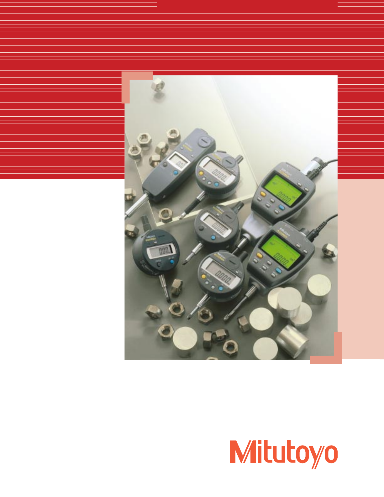
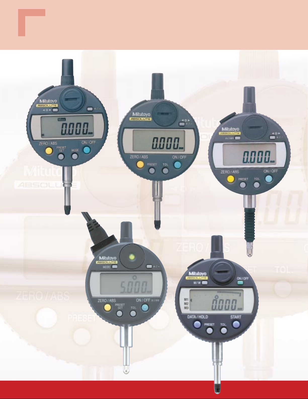
Digimatic Indicators
Bulletin No. 1824
Digital indicators with Absolute encoders
Page 2
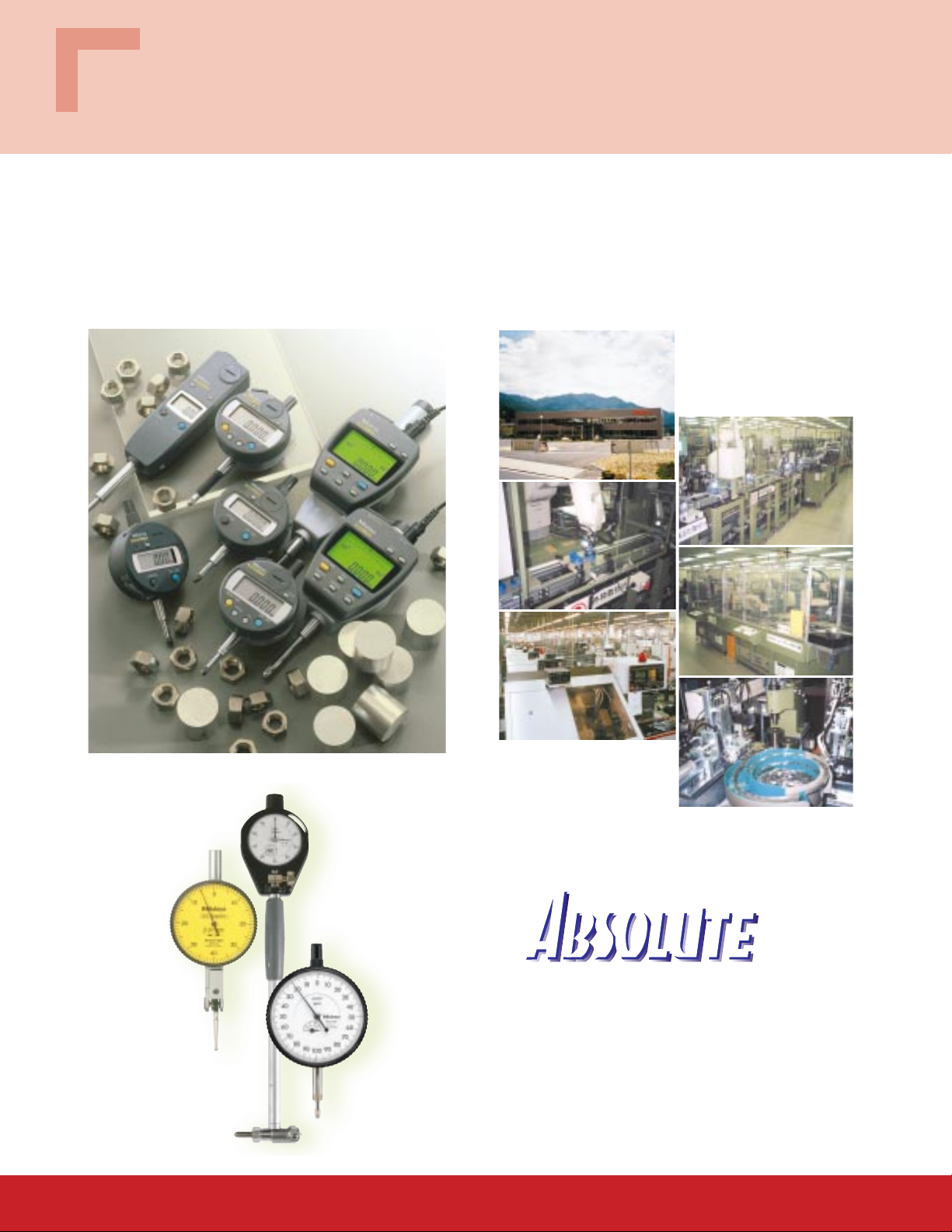
Mitutoyo Digimatic Indicators
The highest in accuracy, reliability and durability
More than 11 million indicators have been produced since production began in 1959. Advanced indicator production
lines have been integrated with fully automated assembly and inspection processes, yielding indicators used in every
part of the world. The plant also produces and ships test indicators, bore gages, etc. Moreover, we are increasing the
production of Digimatic indicators to meet the ever increasing demand for digital gaging in manufacturing.
Nakatsugawa Plant
Site area: 46,800m
Date of establishment: July, 1997
2
Bore gages
Test indicators
Dial/Digimatic
indicators
Mitutoyo’s leading-edge ABSOLUTE encoder never forgets its
absolute origin throughout the entire battery life, unless it is
otherwise preset for a different setup. It immediately indicates
the absolute position of the spindle at power-on, ready to begin
measuring. This technology also eliminates spindle over-speed
error, a phenomenon that usually happens with incremental
type indicators.
2
Page 3
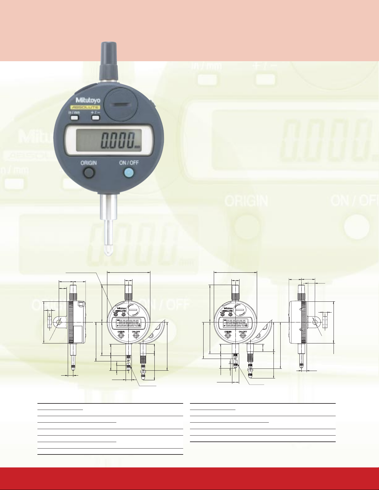
ABSOLUTE IDS
543-692
Dimensions
inch/mm type only
17.5
20
10.6
Ø60.4
Ø10.5
Unit: mm
.5”/12.7mm range model
Simple key functions in an economical package
Technical Data
•Display: LCD
•Functions: Origin setting, power on/off, counting
direction switching, inch/mm conversion (inch/mm
type), SPC data output
•Battery: SR44 (1pc.) (938882)
•Battery life: 20,000 hours in continuous use
•
Stem diameter: 3/8” (ANSI/AGD type) or 8mm (ISO/JIS type)
•Contact point: Carbide ball (ISO/JIS type) or steel ball
(ANSI/AGD type)
•Measuring force: 2.0N or less
2.5N or less (Dust-proof type with rubber boot)
•Dust-water protection level: Conforming to IP42
Conforming to IP53 (Dust-proof type with rubber
boot)
•Alarm: Low battery voltage, scale contaminations, ABS
data Composition error
•Operating temperature: 0°F to 104°F (0˚C to 40˚C)
•Mass: .33 lbs./150g (.26 lbs./120g)*
*0.01mm (.005”/0.01mm) resolution type
Ø2 3/8"
Ø13/32"
.69" 3/4"
Unit: inch
3/8"
54.4
52.2
46.5
16
21.2
67.4
13
7.3
0
Ø8
-0.009
37.2
Dust-proof type
M2.5x0.45
5
Ø58.4
Ø6.5
7.3
Note: The lug is not provided for the flat-back type.
Specifications (ISO/JIS type)
Order No. Accuracy Resolution Range
Back w/lug Flat-back
543-690 543-690B 0.003mm 0.001mm 12.7mm
543-694* 543-694B* 0.003mm 12.7mm
543-681 543-681B 0.02mm 0.01mm 12.7mm
513-691 513-691B .00012” .00005”/.0.001mm .5”/12.7mm
543-695* 543-695B* .00012”
543-682 543-682B .0008” .0005”/0.01mm .5”/12.7mm
* Dust-proof type with rubber boot
2.06"
1.74"
2"
35/64"
.79"
1/4"
3/8" DIA
#4-48UNF
.42"
1 5/8"
2 9/16"
1.46"
Dust-proof type
Note: The lug is not provided
1/4"
Ø1/4"
.29"
for the flat-back type.
Specifications (ANSI/ADG type)
Order No. Accuracy Resolution Range
Back w/lug Flat-back
543-692 543-692B .00012” .00005”/0.001mm .5”/12.7mm
543-696* 543-696B* .00012”
543-693 543-693B .00012” .0001”/0.001mm .5”/12.7mm
543-683 543-683B .0008” .0005”/0.01mm .5”/12.7mm
* Dust-proof type with rubber boot
3
Ø2.30"
Page 4
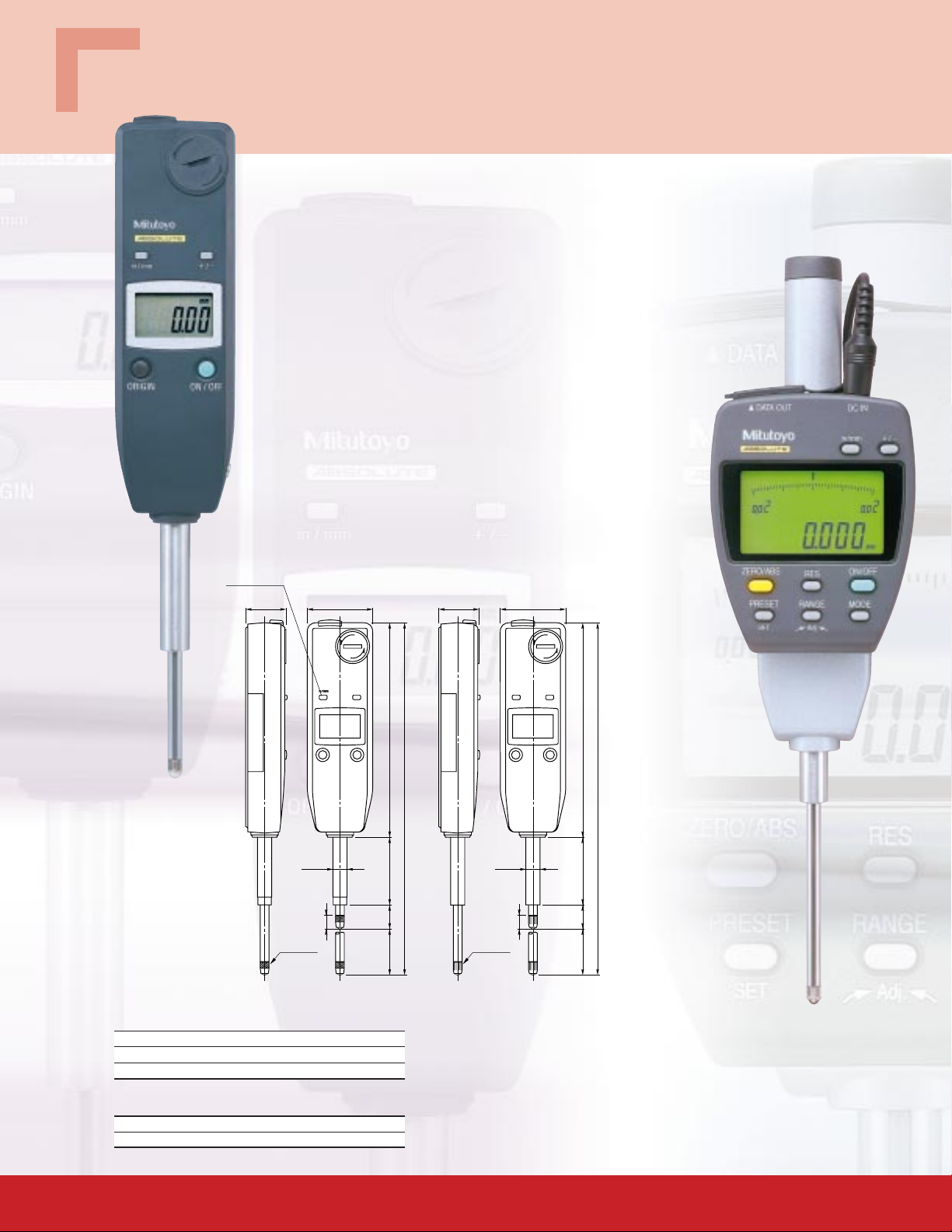
1”/25.4mm range mode with slim body design
1”/25.4mm, 2”/50.8mm range models
575-123
Technical Data
•Display: LCD
•Functions: Origin setting, Power on/off, inch/mm
conversion (inch/mm type), Counting direction
switching, SPC data output
•Battery: SR44 (1pc.) (938882)
•Battery life: 20,000 hours in continuous use
•
Stem diameter: 3/8” (ANSI/AGD type) or 8mm (ISO/JIS type)
•Contact point: Carbide ball (ISO/JIS type) or steel ball
(ANSI/AGD type)
•Measuring force: 1.8N or less
•
Dust-water protection level: Conforming to IP42
•Alarm: Low battery voltage, Scale contaminations
•Operating temperature: 0˚F to 104˚F (0˚C to 40˚C)
•Mass: .31 lbs./140g
inch/mm type only
ISO/JIS type ANSI/ADG type
23 38
Unit: mm
.91"
1.50"
Unit: inch
Multipurpose design
0
Ø8
-0.009
Dimensions
7.3
M2.5x0.45
Specifications (ISO/JIS type)
Order No. Accuracy Resolution Range
575-121 0.02mm 0.01mm 25.4mm
575-122 .0008” .0005”/0.01mm 1”/25.4mm
Specifications (ANSI/ADG type)
Order No. Accuracy Resolution Range
575-123 .0008” .0005”/0.01mm 1”/25.4mm
1264014.327
207.3
3/8DIA
.25"
#4-48 UNF
4.96"1.58".53"1.06"
8.13"
543-558A
2”/50.8mm range model
4
Page 5

ABSOLUTE IDF
FEATURES
Intuitive display
•Large LCD with backlighting
•Numerical/analog bar indication
•
Changing of green/red backlight color
for easy Go/NG reading
Green indication for GO
judgment
Red indication for ±NG judgment
•The resolution can be switched
between .001”/.0005”/.0001”/
.00005” (or 0.001mm/0.01mm).
•The display range of the analog bar
can be changed.
Peak hold/runout measurement
•Displays the maximum or minimum
value during measurement.
•Displays a runout (max. – min. value)
during TIR measurement.
Backup memory
•Retains the setup conditions (peak
hold, tolerance judgment) even if the
power has been turned off.
Measurement can be continued as
soon as the power is turned back on.
Dimension
0
Lower limit
1.70" (43.3)
.43" (11)
A
Upper limit
B
Min. value
Max. value
C
2.6" (66)
Ø.77" (Ø19.6)
Runout
D
inch/mm type only
Technical Data
•Display: LCD
•Functions: Resolution switching, Origin-set
(presetting), Power on/off, Zero-set, MAX/
MIN value hold, Runout measurement,
inch/mm conversion (inch/mm type),
Counting direction switching, SPC data
output, Function lock, Measurement
condition memory
•Power supply: 9V DC (via AC adaptor),
500mA
•Stem diameter: 3/8” (inch/mm type) or
8mm (mm type)
•Contact point: Carbide ball (mm type) or steel
ball (inch/mm type)
•Measuring force:
1.8N or less (1”/25.4mm range type)
2.3N or less (2”/50.8mm range type)
•
Dust-water protection level: Conforming to IP30
•Alarm: Over flow error, Tolerance limit setting
error, Scale contaminations
•Operating temperature: 0˚F to 104˚F
(0˚C to 40˚C)
•Mass: .53 lbs./240g (1”/25.4mm range type)
.73 lbs./330g (2”/50.8mm range type)
Unit: inch (mm)
1.70" (43.3)
.43" (11)
2.6" (66)
Ø.77" (Ø19.6)
inch/mm
type only
543-552A
1”/25.4mm range model
Specifications (ISO/JIS type)
Order No. Accuracy Resolution Range
543-551A 0.003mm 0.001mm 25.4mm
543-557A 0.003mm 0.001mm 50.8mm
(70)
(84.8) 2.22" (56.5)
(19.5)
(Ø8 )
(26)
M2.5x0.45
thread
3/8"DIA
inch/mm
type
3.28" (83.2)
3.74"
4.32"
.68"
2.05"
3.28" (83.2)
2.67"
3.30"
.68"
0
-0.009
inch/mm
type
3/8"DIA
1.02"
#4-48UNF
thread
(97.3)
(110.6) 3.35" (85.2)(52)
(19.5)
0
-0.009
(Ø8 )
M2.5x0.45
thread
#4-48UNF thread
Specifications (ANSI/ADG type)
Order No. Accuracy Resolution Range
543-552A .00012” .00005”/0.001mm 1”/25.4mm
543-558A .00012” .00005”/0.001mm 2”/50.8mm
5
Page 6
ABSOLUTE IDC
Standard .5”/12.7mm, 1”/25.4mm, 2”/50.8mm range models
Various designs for a wide range of applications
Peak Holding Type
543-260
Standard Type
543-250
Dust-proof Type
543-259
Signal Output Type
543-282
Designed for Bore Gage
543-264B
6
Page 7

Standard Type
FEATURES
Tolerance judgment
•GO/±NG judgment can be performed by setting upper and lower
tolerance limits. The judgment result (GO/±NG) can be displayed in
full-size characters.
Technical Data
•Display: LCD (indicator face: 330˚ rotation)
•Functions: Origin set (preset), Power on/off, Zero setting, Counting
direction switching, GO/±NG judgment, inch/mm conversion (inch/
mm type), SPC data output
•Battery: SR44 (1pc.) (938882)
•Battery life: 5,000 hours in continuous use
•
Stem diameter: 3/8” (ANSI/AGD type) or 8mm (ISO/JIS type)
•Contact point:
•Measuring force: 1.5N/0.9N* or less (.5”/12.7mm range models),
1.8N or less (1”/25.4mm range models),
2.3N or less (2”/50.8mm range models)
*543-270/543-270B/543-271/543-271B/543-272/543-272B
•Dust-water protection level: Conforming to IP42
•Alarm: Low battery voltage, Scale contaminations, Over flow error,
Tolerance limit setting error
•Operating temperature: 0˚F to 104˚F (0˚C to 40˚C)
•Mass: .35 lbs./160g (.5”/12.7mm range models),
.42 lbs./190g (1”/25.4mm range models),
.62 lbs./280g (2”/50.8mm range models)
Carbide ball (ISO/JIS type) or steel ball (ANSI/AGD type)
Specifications (ISO/JIS type)
Order No. Accuracy Resolution Range
Back w/lug Flat-back
543-250 543-250B 0.003mm 0.001mm 12.7mm
– 543-450B 0.003mm 25.4mm
– 543-460B 0.006mm 50.8mm
543-290 543-290B 0.005mm 0.01mm 12.7mm
543-270 543-270B 0.02mm
– 543-457B 0.005mm 25.4mm
– 543-454B 0.03mm
– 543-464B 0.04mm 50.8mm
543-251 543-251B .00012” .00005”/0.001mm .5”/12.7mm
– 543-451B .00012” 1”/25.4mm
– 543-461B .00025” 2”/50.8mm
543-291 543-291B .0002” .0005”/0.01mm .5”/12.7mm
543-271 543-271B .0008”
– 543-458B .0002” 1”/25.4mm
– 543-455B .0012”
– 543-465B .0016” 2”/50.8mm
Specifications (ANSI/AGD type)
Order No. Accuracy Resolution Range
Back w/lug Flat-back
543-252 543-252B .00012” .00005”/0.001mm .5”/12.7mm
– 543-452B .00012” 1”/25.4mm
– 543-462B .00025” 2”/50.8mm
543-253 543-253B .00012” .0001”/0.001mm .5”/12.7mm
– 543-453B .00012” 1”/25.4mm
– 543-463B .00025” 2”/50.8mm
543-292 543-292B .0002” .0005”/0.01mm .5”/12.7mm
543-272 543-272B .0008”
– 543-459B .0002” 1”/25.4mm
– 543-456B .0012”
– 543-466B .0016” 2”/50.8mm
Low measuring force type
FEATURES
Low measuring force of 0.4N - 0.7N
•The low measuring force type is specially designed for elastic
workpieces such as plastic parts.
Technical Data
•Measuring force: 0.4N to 0.7N
Note: Other specifications are same as those of the above standard type.
Specifications
Order No. Accuracy Resolution Range
Back w/lug Flat-back
543-254 543-254B 0.003mm 0.001mm 12.7mm
543-274 543-274B 0.02mm 0.01mm 12.7mm
543-255 543-255B .00012” .00005”/0.001mm .5”/12.7mm
543-256* 543-256B* .00012”
543-275 543-275B .0008” .0005”/0.01mm .5”/12.7mm
543-276* 543-276B* .0008”
*ANSI/AGD type
Dust-proof type
FEATURES
IP53 dust/water protection level
•The IP53 protection level structure of the dust-proof type allows the
indicator to resist dust and contaminants for safe operation in
harsh machine shop environments.
Technical Data
• Measuring force: 2.0N or less
• Dust/Water protection level: Conforming to IP53
Note: Other specifications are same as those of above standard type.
Specifications
Order No. Accuracy Resolution Range
Back w/lug Flat-back
543-257 543-257B 0.003mm 0.001mm 12.7mm
543-277 543-277B 0.02mm 0.01mm 12.7mm
543-258 543-258B .00012” .00005”/0.001mm .5”/12.7mm
543-259* 543-259B* .00012”
543-278 543-278B .0008” .0005”/0.01mm .5”/12.7mm
543-279* 543-279B* .0008”
*ANSI/AGD type
7
Page 8

ABSOLUTE IDC
Peak Holding Type
FEATURES
Tolerance judgment
•
GO/±NG judgment is performed by setting the upper and lower
tolerances for maximum, minimum and runout values.
•High-speed sampling ratio of 50 times per second.
Peak hold function
•The maximum, minimum, or runout value can be displayed during
Technical Data
•Functions: Origin set (preset), Power on/off, Zero setting,
Counting direction switching, GO/±NG judgment,
max./min./runout value holding
inch/mm conversion (inch/mm type), SPC data output, Function
lock
Note: Other specifications are the same as those of the standard type.
measurement.
Upper limit
9.000
A
0
Lower limit
Spindle position 0 – A – B – C – D
Normal mode 0.000 5.000 -5.000 10.000 0.000
Max. mode 0.000 5.000 5.000 10.000 10.000
Min. mode 0.000 0.000 -5.000 -5.000 -5.000
TIR mode 0.000 5.000 10.000 15.000 15.000
B
Max. value (12.000)
C
Min. value (-5.000)
Runout
D
Specifications
Order No. Accuracy Resolution Range
Back w/lug Flat-back
543-260 543-260B 0.003mm 0.001mm 12.7mm
543-261 543-261B .00012” .00005”/0.001mm .5”/12.7mm
543-262* 543-262B* .00012”
543-263* 543-263B* .00012” .0001”/0.001mm .5”/12.7mm
*ANSI/AGD type
Signal Output Type
FEATURES
GO/±NG signal output
•With the max./min. value holding function, this indicator can
output the signal of the GO/±NG judgment result against the peak
values set to an external device like a
sequencer through the NPN opencollector.
Substitute for the mechanical/electrical
contact, the judgment is carried out by
calculating the measurement data
obtained. This provides high
GO
-NG
+NG
4m, Ø5mm,
Core wire AWG/24
20mm
reliability with no
deterioration of the contact
point and volume
adjustment.
Green/red LED for GO/±NG indication
•The GO/±NG judgment result is also indicated by
the green/red LED and the “<,O,>” signs on LCD.
IP54 dust/water protection level
•
This indicator achieves IP54 protection level to resist dust and
contaminants for safe operation in harsh shop environments.
Technical Data
•Functions: Origin set (preset), Power on/off, Zero setting, Counting
direction switching, GO/±NG judgment, max./min./runout value
holding, inch/mm conversion (inch/mm type), Function lock
•Dust-water protection level: Conforms to IP54
Note: Other specifications are the same as those of the standard type.
Specifications
Order No. Accuracy Resolution Range
Back w/lug Flat-back
543-280 543-280B 0.003mm 0.001mm 12.7mm
543-281 543-281B .00012” .00005”/0.001mm .5”/12.7mm
543-282* 543-282B* .00012”
543-283* 543-283B* .00012” .0005”/0.01mm .5”/12.7mm
*ANSI/AGD type
1000pF
Output voltage: Max. 24V
Output current: Max. 30mA
Output saturated voltage: Max. 0.3V
DC+12-24V
24kΩ
Input current:
Max. 10mA
1000pF
Signal output
Wire color Signal I/O Description
Black -V (GND) – Connected to minus (-) terminal
Red +V (plus power voltage) I Supply power voltage (12VDC - 24VDC)
Orange -NG O
Green OK O
Brown +NG O
Yellow PRESET_RECALL/ZERO I
Blue HOLD_RESET I
Shield FG (Frame Ground) – Connected to the ground.
OUT
SG
Use a nonvoltage output
such as an open
collector output
or relay output.
OUT
SG
Load
Upper limit
value
Lower limit
value
+NG
Max. 40ms
OK
-NG
Power
Signal output
Signal input
Tolerance judgment result output terminals (NPN
open-collector output): Only the terminal
corresponding to a judgment result is set to the
low level. (See the output circuit diagram.)
External input terminals (no-voltage input): If the
relevant terminal is set to the low level, its signal
becomes true. (See the input circuit diagram.)
Max. 40ms
Max. 700ms
Min. 30ms
8
Page 9

Designed for Bore Gage
FEATURES
Exclusive design for bore gage use
Lower limit value
•The minimum value holding function provides simple,
accurate and stable ID measurement.
•Up to three sets of reference diameter and upper/lower
Tolerance
judgment (OK)
tolerance values can be stored to simplify the start-up
key operation in the repeatable hole inspection of
mixed diameter sizes.
•An analog bar indication is integrated to enhance
readability.
Technical Data
•
Functions: Origin set (preset), Power on/off, Data hold, GO/
±NG judgment, min. value holding, inch/mm conversion
(inch/mm type), SPC data output, function lock
Note: Other specifications are same as those of the
standard type.
Specifications
Order No. Accuracy Resolution Range
Back w/lug Flat-back
– 543-264B 0.003mm 0.001mm 12.7mm
– 543-265B .00012” .00005”/0.001mm .5”/12.7mm
Specifications (ANSI/AGD type)
Order No. Accuracy Resolution Range
Back w/lug Flat-back
– 543-266B 0.003mm .00005”/0.001mm 12.7mm
– 543-267B .00012” .0001”/0.001mm .5”/12.7mm
20 27.6
10.6
Ø10.5
38.5
11
Ø19.6
38.5
11
Optional bore gage
Order No. Range
526-170 0.95 - 1.55mm
526-160 1.5 - 4.0mm
526-150 3.7 - 7.3mm
526-101 7.0 - 10.0mm
526-102 10 - 18mm
511-126 18 - 35mm
511-127 35 - 60mm
511-132 50 - 150mm
* Set No. with IDC 18-150mm:
511-905 .7”-6”: 511-915
Unit: mm
Ø19.6
Min. value (blinking)
1.52"
.43"
Upper limit value
Diameter (min. value held)
.77"
Current value
1.52"
.43"
Detecting a minimum point
for diameter
Unit: inch
.77"
Ø6.5
Ø54
5
16
M2.5x0.45
21.2
7.6
7.3
With lug type
Dimensions
Ø60.5
Ø8
Ø54
0
-0.009
4m, Ø5mm,
Core wire AWG/24
20
10.6
5
Ø6.5
49.6
54.4
16.5
M2.5x0.45
7.6
40.8
Ø60.5
67.4
49.6
43.5
M2.5x0.45
7.3
20
13.5
37.2
7.3
Ø60.5
Ø8
Ø10.5
Ø8
0
-0.009
0
-0.009
56.5
84.8
19.5
M2.5x0.45
65.3
7.3
ISO/JIS type
Ø2 3/8"
Ø60.5
13/32"
.68"
.9/16"
3.30" 2.22"
2" 1.95"
2.62"
ANSI/AGD type
3/8" DIA
110.6 85.2
0
Ø8
-0.009
19.5
1/4"
1/4"
2.13" DIA
#4-48 UNF
1.66"
3/4" 1.09"
3/8"
.3"
#4-48 UNF
.25"
Ø2 3/8"
3/8" DIA
.79"
1/4"
#4-48 UNF
.25"
Ø2 3/8"
3/8" DIA
4.32" 3.35"
.68"
9
Page 10

1.09" (27.6)1.09" (27.6)
.30" (7.6).30" (7.6)
ø2 3/8" (ø60.5)
ø2 3/8" (ø60.5)
ø2.13" (ø54)
ø2.13" (ø54)
17.4" (44.2)
2.00" (50.95)
.79"
(20.05)
1/4"
(6.35)
9/16"
(14.2)
M2.5x0.45 thread
1.95" (49.6)
(54.4)
(46.5)
(16.5)
(21.2)
(7.3)
(ø8
0
–0.03
0
–0.009
No.4-48 thread
Unit: inch (mm)
(ø9.52
3/8"DIA
ø13/32" (ø10.5)
))
CALCULATION-TYPE DIGIMATIC INDICATOR
The Calculation-Type Digimatic indicator incorporates an
internal calculation function in place of spindle displacement.
With fixtures, measurements such as inside diameter and
radius of curvature measurement can easily be obtained
without the trouble of conversion tables or equivalents.
Technical Data
Fixture example
•Display: LCD
•Functions: Calculation, Zero set, Presetting, Tolerance
judgment, Hold button, Output and Switching ABS/INC
conversion
•Battery: SR44 x 1pc.
•Battery life: 120months under normal use
•Stem diamter: 3/8” DIA or ø8mm (ø9.525mm)
Hole diameter
•Contact point: Carbide ball (ISO/JIS type) or steel ball
(ANSI/AGD type)
•Measuring force: 1.5N or less
•Dust/Water protection level: Conforming to IP42
•Alarm: Low battery voltage, Scale contaminations,
Tolerance limit setting error, ABS data composition
error, Over flow error
Outside diameter
•Operating temperature: 0˚F to 104˚F (0˚C to 40˚C)
•Mass: .35lbs / 160g
Specifications
Order No. Accuracy Resolution Range
543-285B 0.003mm (0.00012") or less 0.002mm to 1mm 12.7mm
543-286B 0.003mm (0.00012") or less .00001”/0.003mm to .5”/12.7mm
543-287B .05”/1mm
All instruments in this series are of the flat-back type.
Groove width
Chamfer hole diameter
Radius of curvature
Inside diameter
10
Page 11

Calculation function
The Absolute Digimatic indicator performs internal
calculations using the formula Ax+B+Cx
-1
(assuming
spindle displacement as x) while the specified coefficients
Tolerance judgment
Setting the upper/lower limits produces a display of
tolerance judgments, thus making it easy to calculate for
extreme accuracy.
A, B and, C can be set with respect to the purpose of
measurement or dimensions of the fixtures. This unique
feature allows you to read your measurements directly,
without making conversions.
Large display LCD
A large LCD makes it easy to read the settings of
arithmetic coefficients, as well as tolerance judgments
and other aspects of the measuring process.
Data output
The Absolute Digimatic indicator can output data to a
data processor. This allows the recording of measuring
results and the configuration of a system that includes
process control via the data processor. Additionally,
Display hold
The Display Hold function is useful when LCD viewing is
difficult during measurement.
Maximum value and minimum value can be held, as well.
arithmetic coefficients can be set from a connected
personal computer rather than the indicator itself.
Calculation examples of arithmetic coefficients
(Calculate arithmetic coefficients A, B, and C with a scientific calculator and then set the value you've determined. For details, refer to the table below.)
Fixture
Contact point Cone Ball Cone — — —
2L
r
R
R=Ax+B+Cx
–
–
Dimension
X: Spindle
displacement
Measurement
item
Calculation
formula
A
Arithmetic
Coefficient
Origin setting
position
(the position
when x=0)
Indicated
value when
origin setting
(indicated value
when x=0)
B
C
2L
r
x
H
D
D= Diameter/Feeler/
Groove width
H= Countersink depth
D=Ax D=Ax+B H=Ax+B D=Ax R=Ax R=Ax+B+Cx
–2tan
2
0 00
000 0
0 Value for coefficient B 0 0 (Overflow) (Overflow)
D= Diameter/Feeler/
Groove width
H= Countersink depth
–2tan –1
2
1
–tan
2r r
cos
2
2
x
d
D
D= Hole diameter/
Feeler/
Groove width
–2tan
1
sin
2
–1
d
–
2tan
2
x
D
2R=Outside diameter 2R=Outside diameter 2R=Inside diameter
2
–
Contact point free
x
r
R
sin
2
1–sin
2
Various fixtures suited for individual workpieces can be prepared.
Measuring accuracy is subject to fixture accuracy.
x
R
-
1
1
2
2
L
2
x
-
1
1
2
r–r
2
L
2
11
Page 12

Note:
All our product details, in particular the illustrations, drawings,
dimension and performance details and other technical
specifications contained in this publication are to be considered
to be approximate average values. To this extent, we reserve
the right to make changes in design, technical data, dimensions
and weight. Our specified standards, similar technical rules
and technical specifications, descriptions and illustrations of the
products are correct at the time of printing. The current version
of our general terms and conditions also apply. Only offers which
we have submitted can be considered to be definitive.
©2005 Mitutoyo America Corporation, Aurora IL We reserve the right to change specifications and prices without notice. 0105-17 • Printed in USA •␣ January 2005
 Loading...