

Page 1
NOTICE
±3°
B
WARNING
CAUTION
NOTICE
User's Manual No.99MAB047A
en
Absolute Digimatic Micrometer
with Adjustable Measuring Force
CLM-QMX, CLM-DKX
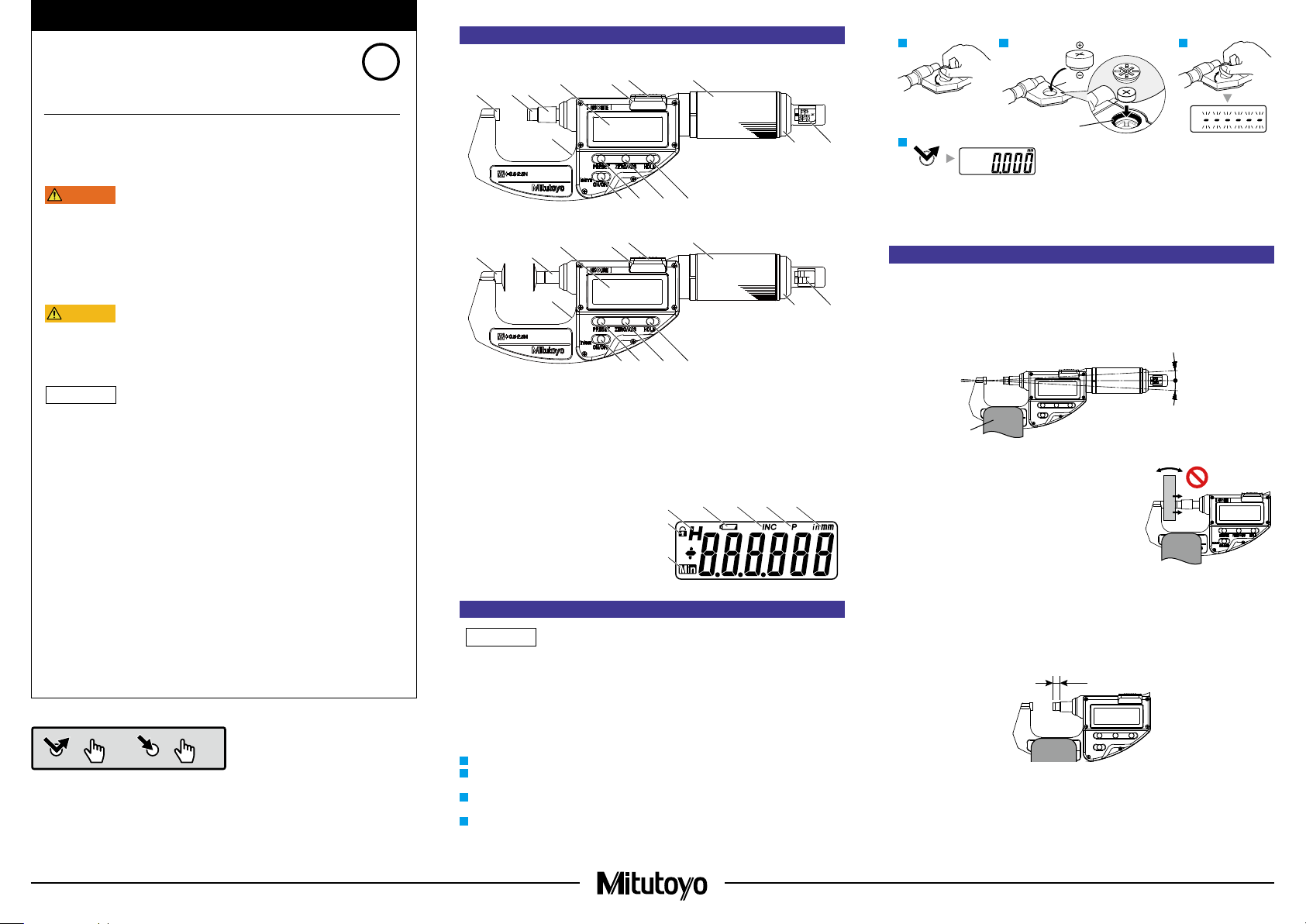
1. Names of Components
● CLM-QMX
② ③
①
⑥ ⑦
⑤④
1 2 3
SR44
No. 938882
Safety Precautions
To ensure operator safety, use this product in conformance with the directions, functions
and specications given in this User's Manual.
Use under other conditions may compromise safety.
• Always keep batteries out of reach of children. If swallowed, consult a physician
immediately.
• Batteries should never be short-circuited, disassembled, deformed or come in contact with
extreme heat or ames.
• If battery alkaline liquid comes in contact with the eyes, ush eyes immediately with clean
water and consult a physician. If battery alkaline liquid comes in contact with the skin,
ush the exposed area thoroughly with clean water.
• Never attempt to charge the primary battery. Never reverse the positive-negative terminals
when mounting. Improper battery handling or mounting may cause the battery to explode,
cause battery leakage and/ or serious bodily injury or malfunctioning.
• The measuring faces of this product are sharp. Always handle with care to avoid injury.
• Do not disassemble or modify. This may cause damage.
• Do not use or store the product in a place with sudden temperature changes. Adapt the
product to ambient temperature before use.
• Do not store the product in a place with high humidity or a lot of dust.
• Do not apply excessive force or subject to sudden impacts such as dropping.
• Be sure to perform reference point setting before measurement.
• Remove dust, cutting chips, etc. before and after use.
• When cleaning, wipe this product with a soft cloth moistened with diluted neutral
detergent. Do not use an organic solvent such as thinner, which may cause the product to
deform or malfunction.
• The spindle structure prevents pulling out, so do not try to forcibly retract in excess of the
measurement range. This may cause damage.
• Dirt on the spindle may lead to malfunction. If the spindle becomes dirty, wipe it clean with
a cloth containing a small amount of alcohol and apply a small amount of micrometer oil
(Part No. 207000).
• Do not write numbers, etc. with an electric pen. This may cause damage.
• The battery supplied is for conrming the functions and performance of the product. Note
that this battery may not fulll the expected life.
• The display of this product automatically turns off if not used for 20 minutes or more.
Press the [ON/OFF] button to turn the display on again.
• If the product is to be out of use for 3 months or more, remove the battery before storage.
Liquid leakage from the battery may damage the product.
• Malfunction or damage due to depleted batteries, etc. is not covered by the warranty.
Button icon operation
< 1 s
=
≥ 2 s
=
Date of publication: May 28, 2018
⑭
⑫⑬ ⑪ ⑩
● CLM-DKX
⑥ ⑦
①
②
⑤④
1.0
2.0
1.5
2.5
0.5
⑭
⑫⑬ ⑪ ⑩
Anvil
①
Spindle
②
Stroke end bush
③
(CLM-QMX only)
LCD
④
Data output connector
⑤
Cover
⑥
Thimble*
⑦
Measuring force selector
⑧
Cover for measuring force
⑨
selector
[HOLD] button
⑩
[ZERO/ABS] button
⑪
[PRESET] button
⑫
[ON/OFF in/mm**] button
⑬
(**only for in/mm model)
Battery compartment
⑭
cover (at rear)
* Thimble (with constant
pressure device): 0.5 N to
2.5 N type only
■ Display
Minimum value hold display
①
Function lock display
②
Displayed value hold display
③
Battery voltage low display (error display)
④
Incremental measurement (INC) display
⑤
Preset display
⑥
Unit display
⑦
③
②
①
④
⑤ ⑥ ⑦
2. Installing the Battery
• Be sure to use SR44 (silver oxide button battery No. 938882) for the battery.
• Always align the battery compartment cover with the threads and install so that the seal does
not protrude. The product may display an error or malfunction if the battery compartment cover
or seal is not mounted correctly.
• Re-installing the batteries will erase the PRESET value (reference point) setting. Perform
reference point setting again (refer to "5. PRESET Value (Reference Point) Setting").
• Follow local rules and regulations regarding battery disposal.
The battery is not installed into the product at purchase. Install the battery as follows.
Rotate the battery compartment cover counter-clockwise to remove it.
1
Install the battery (button type silver-oxide battery; Part No. 938882) with the positive side
2
facing up.
Position the battery compartment cover and rotate clockwise to attach.
3
Moving on, set the PRESET value (reference point).
Press the [PRESET] button.
4
Count display appears and counting starts.
⇨
Mitutoyo Corporation 1-20-1 Sakado, Takatsu-ku, Kawasaki City, Kanagawa 213-8533
Seal
⑧⑨
4
PERSET
Tips
If an abnormal display is shown, such as an error display or not counting, etc., try removing the
batteries and reinstalling.
3. Precautions for Use
N
⑧⑨
■ Measurement Orientation
Only a horizontal measurement orientation (horizontal measurement axis for the anvil, spindle, and
thimble) is possible for this product.
In order to perform measurement within the guaranteed accuracy, use a micrometer stand (A) and
keep the tilt from horizontal orientation within ±3 °. Note that the measuring force will change by
±0.3 N at ±30 ° tilt from horizontal orientation, as a guideline.
A
■ Measuring Force
Moving the workpiece horizontally applies force more than the
set measuring force to the spindle. Hold the workpiece so as to
avoid applying any force more than the set measuring force to
the spindle during measurement.
■ Temperature
This product, especially the 0.001 mm resolution model, is
easily inuenced by temperature changes. Abrupt temperature
changes should be avoided and sufcient time should be
allowed to adjust to ambient temperature before measuring.
■ Handling the Stroke End Bush (CLM-QMX only)
The stroke end bush acts as a marker for the measurement range (10 mm or 15 mm). Although it
will not directly affect the measurement results, do not move or remove it, in order to prevent
damage. The home position of the marker (B) is 6 mm or 11 mm from the edge of the spindle.
■ Precautions after Use
• After use, clean the entire product and check that none of the parts are damaged.
If using in places exposed to water-based cutting uid, always apply anti-rust treatment after
cleaning.
• For storage, leave a gap of 0.2 to 2 mm open for the measurement surfaces.
• For long-term storage, apply anti-rust treatment to the spindle using micrometer oil (Part No.
207000).
Printed in Japan
Page 2
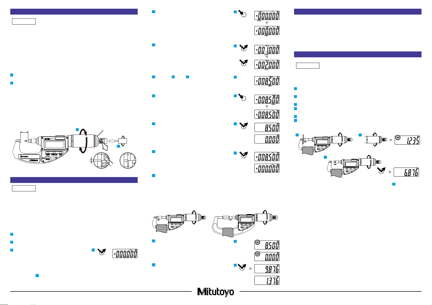
4. Measuring Force Setting
NOTICE
NOTICE
PRESET
3
PRESET
5
6
8
9
12
NOTICE
HOLD
• When setting the measuring force, be sure to retract the spindle to position (A), where the
thimble stops rotating. If the spindle is not sufciently retracted, the proper measuring force
cannot be set.
• Slowly turn the thimble. If the spindle forcibly reaches position (A), where rotation stops, it may
lead to damage.
• After changing the measuring force, be sure to perform reference point setting. Otherwise, this
may cause errors. (Refer to "5. PRESET Value (Reference Point) Setting")
• Set the measuring force within the specications. Measuring force lower than the specication
range is not guaranteed, and spindle action will be negatively affected.
This product is a variable measuring force type micrometer. Measuring force settings can be
changed as follows.
Slowly retract the spindle to the position (A) where the thimble cannot be turned any further.
1
maximum measurement length + 0.5 mm
A ≧
Turn the measuring force selector with the provided slotted screwdriver to set the measuring
2
force.
Tips
Measuring force values (a) and scale lines (b) are indicated on the measuring force selector.
Adjust so that the scale line for the target measuring force is on the edge of the cover for
measuring force selector, and the central line (c) is within the setting range [between the two
lines (c)] of the cover for the measuring force selector.
Figure B below: Setting example for measuring force 0.5 N
Figure C below: Setting example for measuring force 2 N
Rotate the measuring force selector twice, to move it by one measuring force setting graduation.
A
1
Cover for measuring force
selector
B
c
5. PRESET Value (Reference Point) Setting
• For reference point setting, use a periodically inspected reference gage (gauge block,
micrometer standard bar, etc.).
• Reference point setting and measurement should be made in the same orientation and
conditions and with the same procedure as below.
• When using CLM-DKX, if measuring with only part of the measuring surface, perform reference
point setting under the same conditions as the measurement.
• If the reference point changes due to temperature changes, recongure the PRESET value
(reference point).
Set the reference point according to the following procedure.
Mount the product horizontally to a micrometer stand (refer to "3. Precautions for Use ■ Measurement
1
Orientation").
Clean both anvil and spindle measurement surfaces, together with the micrometer standard bar
2
if it is used to remove all debris or dust.
Press the [PRESET] button.
3
[P] blinks on the LCD, and the registered preset
⇨
value is displayed.
The preset value immediately after battery
replacement is [0.000 mm].
• If not changing the preset value
Proceed to step
• If changing the preset value
Change the preset value according to the following procedure.
.
8
Again, press and hold the [PRESET] button until the
4
target digit starts to blink.
[P] lights up and each digit starts to blink in turn.
⇨
Tips
While the [PRESET] button is held down, the blinking digit
will move to the right in turn. Release the [PRESET] button,
and the movement of the blinking digit will stop.
Press the [PRESET] button to change to the target value.
5
The value changes each time you press the
⇨
[PRESET] button.
Repeat step 4 and step 5 to change the value for all digits.
6
Setting example: 8.500 mm (nominal length of the
standard bar)
Again, press and hold the [PRESET] button, and then
7
release it when [P] on the LCD starts to blink.
Press the [PRESET] button.
8
[P] turns off and the preset value is registered.
⇨
(Lower section: If not changing the preset value
[0.000])
4
PRESET
PRESET
7
PRESET
PRESET
6. Selecting Measurement Type
Measurement modes include the following 2 measurement types. Select as appropriate for the
workpiece.
(Refer to "8. Button Functions ■ Switching Measurement Type/Displayed Value Zero Reset")
• Absolute measurement (ABS)
Measures the length based on the set PRESET value (from the reference point).
• Incremental measurement (INC)
Zeros the displayed value with the master and measures a difference between the master and a
workpiece.
7. Measurement Method
The displayed value will be held ([H] display lights up) as soon as the set measuring force is
applied. To obtain stable measurement results, turn the thimble slowly and stop it as soon as the
[H] display lights up.
Mount the product horizontally to a micrometer stand (refer to "3. Precautions for Use ■ Measurement
1
Orientation").
Clean both the anvil and spindle measurement surfaces and the workpiece to remove all debris
2
or dust.
Slowly turn the thimble until both measurement surfaces make light contact with the workpiece.
3
Further turn the thimble by 1/10 rotation to push the spindle in.
4
[H] display lights up and the displayed value is automatically held.
⇨
Read the indicated value.
5
Turn the thimble in the opposite direction by 1/10 rotation or more to retract the spindle, and
6
then press the [HOLD] button.
[H] display turns off and the hold is released. The current spindle position is displayed.
⇨
3 4
2
Press the [PRESET] button.
C
a
b
4
2
9
[P] blinks on the LCD, and the registered preset
⇨
value is displayed.
(Lower section: If the preset value is [0.000])
If the measurement range is 0 to 10 mm or 0 to 15 mm:
10
Slowly turn the thimble until both measurement
surfaces make light contact.
If the measurement range is other than 0 to 10 mm or 0
to 15 mm:
Insert the standard bar between the measurement
surfaces and slowly turn the thimble until both
measurement surfaces make light contact with the
standard bar.
Further turn the thimble by 1/10 rotation to push the
11
spindle in.
[H] display lights up.
⇨
(Lower section: If the preset value is [0.000])
Turn the thimble in the opposite direction by 1/10
12
rotation or more to retract the spindle, and then press
the [HOLD] button.
[H] display turns off and the hold is released. The
⇨
current spindle position is displayed.
(Lower section: If the preset value is [0.000])
PRESET
Tips
• Hold will not be released even when the [HOLD] button is pressed in step 4. To make the
[HOLD] button function, retract the spindle until no measuring force is applied.
• If the [PRESET] button is accidentally pressed during measurement, press the [ZERO/ABS]
button to return to the former state. If this does not enable the product to recover, perform
reference point setting once more.
11
HOLD
Mitutoyo Corporation 1-20-1 Sakado, Takatsu-ku, Kawasaki City, Kanagawa 213-8533
6
Printed in Japan
Page 3

8. Button Functions
ON/OFF
ZERO/ABS
HOLD
NOTICE
1 3 52 4
–: 8(0001)
inch: 1(1000)
■ Power ON/OFF: [ON/OFF in/mm] Button
• Press the [ON/OFF in/mm] button.
Power turns ON.
⇨
• Press and hold the [ON/OFF in/mm] button.
Power turns OFF.
⇨
ON/OFF
■ Switching Measurement Type/Displayed Value Zero Reset: [ZERO/ABS] Button
• Press the [ZERO/ABS] button.
[INC] display lights up and the display is set to zero (incremental measurement).
⇨
• Press and hold the [ZERO/ABS] button.
[ INC] display turns off and the length from the reference point (anvil measurement surface) is
⇨
displayed (absolute measurement).
ZERO/ABS
■ Display Value Hold: [HOLD] button
• Press the [HOLD] button.
[H] display lights up and the displayed value is held.
⇨
The displayed value will not change even if the spindle moves.
• Press the [HOLD] button.
[H] display turns off and the hold is released.
⇨
The current spindle position is displayed.
HOLD
■ Unit Switching (only for in/mm model): [ON/OFF in/mm] Button
• Press the [ON/OFF in/mm] button with the power ON.
Units will switch.
⇨
ON/OFF
9. Function Lock Function (Mistaken Operation Prevention)
This product has a Function Lock function in order to avoid accidental changes to the reference
point position.
Setting the Function Lock causes the [
[ZERO/ABS] button, and in/mm button (export specications only), with only the "Hold Operation"
and "Power ON/OFF Operation" functions enabled.
● Function Lock Function ON/OFF
• First press and hold the [HOLD] button, and then additionally press and hold the [ZERO/ABS] button.
[H] display and [
⇨
] display light up in sequence ([H] turns off rst).
] LCD to light up and disables the [PRESET] button,
HOLD ZERO/ABS
• First press and hold the [HOLD] button, and then additionally press and hold the [ZERO/ABS] button.
[
] display turns off and the Function Lock function is released
⇨
HOLD ZERO/ABS
10. Errors and Troubleshooting
Error Display Causes and Countermeasures
Display Overflow
ABS Synthesis Error
Power Voltage Drop
Hardware Error
Sensor Contamination
Detection Error
The displayed value exceeds the number of digits that can be
displayed.
Normal counting will start again when the thimble is moved in
reverse and the displayed value returns to the number of digits
that can be displayed.
Although this may be momentarily displayed while the spindle is
moving, it is a normal artifact of internal processing. If it occurs
while the spindle is not moving, the internal sensor has failed.
In this case, repair is required: consult with your dealer or agent or
with our sales office.
Battery is depleted.
Replace with a new battery.
A hardware error was generated. In this case, repair is required:
consult with your dealer or agent or with our sales office.
A sudden change in temperature may create condensation on the
detector, or it may be contaminated by other sources.
• Turn the power OFF and allow the product to adapt to the
temperature for about 2 hours.
• If it does not recover after adapting to the temperature, repair is
required: consult with your dealer or agent or with our sales office.
11. Specications
■ Individual Specications
● CLM-QMX
Measur ement r ange : 0 to 15 mm, 15 to 30 mm, 0 to 0.6 in, 0.6 to 1.2 in (0.5 N to 2.5 N type)
:
Instrument error
● CLM-DKX
Measurement range : 0 to 15 mm, 0 to 0.6 in (0.5 N to 2.5 N type)
: 0 to 10 mm, 0 to 0.4 in (2 N to 10 N type)
Instrument error
*1: At 20 °C, excluding quantization error
*1
*1
0 to 10 mm, 10 to 20 mm, 20 to 30 mm, 0 to 0.4 in, 0.6 to 0.8 in, 0.8 to 1.2 in
(2 N to 10 N type)
: ±0.002 mm
: ±0.004 mm
■ Common Specications
Resolution : 0.001 mm, 0.00005 in
Quantization error : ±1 count
Measuring force : 0.5 to 2.5 N, variable (0.5 N to 2.5 N type)
: 2 N to 10 N, variable (2 N to 10 N type)
Measuring force scale : 0.5, 1.0, 1.5, 2.0, 2.5 N (0.5 N to 2.5 N type)
: 2, 4, 6, 8, 10 N (2 N to 10 N type)
Measuring force variation : 0.1 N or less (0.5 N to 2.5 N type)
: 0.4 N or less (2 N to 10 N type)
Set measuring force error : ±(0.1 + set measuring force/10) N (0.5 N to 2.5 N type)
: ±(0.4 + set measuring force/10) N (2 N to 10 N type)
Display : LCD (6-digit and minus sign)
Power supply : Button type silver-oxide battery (SR44 No.938882), x1
Battery life : With typical use approximately 5 years, with continuous use 18,000
Measurement orientation : Horizontal/lateral orientation only (tilt within ±3 ° recommended)
Temperature range : 5 °C to 40 °C (operating temperature), -10 °C to 60 °C (storage
Standard accessories : Slotted screwdriver (Part No. 210183)
Standard bar (CLM1-30QMX, CLM2-30QMX only)
Gauge block (CLM2-10QMX only)
hours or more
temperature)
Mitutoyo Corporation 1-20-1 Sakado, Takatsu-ku, Kawasaki City, Kanagawa 213-8533
12. Output Function
■ Display Value External Output
The displayed value can be output to a device by connecting the product and the external device
with a connection cable (option).
• Always use the 0-size Phillips screwdriver (No.05CZA619) included with the connection cable
(option) when installing/removing screws, and tighten to a torque of 5 to 8 cN • m· or so.
•
Install so that the seal does not protrude. Waterproof functioning will decrease if not installed correctly.
Install connection cables using the following procedure.
Use the Phillips screwdriver included with the connection cable to remove the cover xing screws
1
(M1.7 x 0.35 x 2.5, No.04AAB543).
Remove the cover.
2
Check that the connector seal (No.04AAC126) is correctly installed at the proper position (do
3
not remove the connector seal).
Mount the connection cable plug.
4
Hold the plug manually so that there is no gap between the plug and the Quickmike body, and
5
fasten using the xing screws on the plug.
Connector
seal
■ Output Data Format
3(1100)
4(0010)
5(1010)
(1) Output order
(2) All "F"
(3) Sign
(4) Measured
value
(5) Decimal
point
(6) Unit
(1)
(3)
(2) (4)
+: 0(0000)
MSD LSD
(5)
(6)
mm: 0(0000)
■ Timing Chart
0 msec
100 µsec
100 µsec
100 µsec
*1: DATAsw is LOW while the data output button is being pressed.
*2: The time T5 until DATAsw goes to the LOW level and REQ
processing device performance.
200 msec
T1
140 µsec (Typ:122 µsec)
T2
140 µsec (Typ:122 µsec)
T3
270 µsec (Typ:244 µsec)
T4
is input is determined by the data
13. Options
• Connection cable: No.05CZA662 (1 m)
• Connection cable: No.05CZA663 (2 m)
14. Off-Site Repairs (Subject to Charge)
Off-site repair (subject to charge) is required in the case of the following malfunctions. Contact your
nearest dealer or our sales ofce.
• Faulty spindle operation
If the spindle is scratched, these scratches may interfere while the spindle is retracting, causing
faulty operation.
Operation may also suffer if the spindle is rusted.
• Inconsistent measured values
If a shock is applied to the measurement surfaces, or if burrs appear on the measurement
surfaces. This may affect accuracy.
• Count value error/faulty operation
If the thimble of this product is retracted too far, the internal sensor will be damaged. This may
cause count errors or faulty operation.
Printed in Japan
 Loading...