


Mitsubishi PLFY-P32VAM-E.UK, PLFY-P40VAM-E.UK, PLFY-P50VAM-E.UK, PLFY-P63VAM-E.UK, PLFY-P80VAM-E.UK Service Manual
...SPLIT-TYPE, HEAT PUMP AIR CONDITIONERS
July 2006
No. OC313
REVISED EDITION-B
TECHNICAL & SERVICE MANUAL
|
|
|
|
|
|
|
|
|
|
|
|
Indoor unit |
|
|
|
[Model names] [Service Ref.] |
|||
PLFY-P32VAM-E |
PLFY-P32VAM-E.UK |
||
|
|||
PLFY-P40VAM-E |
PLFY-P40VAM-E.UK |
||
|
|||
PLFY-P50VAM-E |
PLFY-P50VAM-E.UK |
||
|
|||
PLFY-P63VAM-E |
PLFY-P63VAM-E.UK |
||
|
|||
PLFY-P80VAM-E |
PLFY-P80VAM-E.UK |
||
|
|||
PLFY-P100VAM-E |
PLFY-P100VAM-E.UK |
||
|
|||
PLFY-P125VAM-E |
PLFY-P125VAM-E.UK |
||
|
|||
Revision:
•RoHS PARTS LIST is added.
•Some descriptions have been modified.
•Please void OC313 REVISED EDITION-A.
Note:
•This manual does not cover outdoor units.
When servicing them, please refer to the outdoor unit’s service manual.
•RoHS compliant products have <G> mark on the spec name plate.
•For servicing of RoHS compliant products, refer to the RoHS Parts List.
CONTENTS
1. SAFETY PRECAUTION···········
2. PART NAMES AND FUNCTIONS ······
3. SPECIFICATIONS·············
4. 4-WAY AIR FLOW SYSTEM ·········
5. OUTLINES AND DIMENSIONS·······
6. WIRING DIAGRAM············
7. REFRIGERANT SYSTEM DIAGRAM ·····
8. TROUBLE SHOOTING···········
9. DISASSEMBLY PROCEDURE·······
10 . PARTS LIST················ INDOOR UNIT 11. RoHS PARTS LIST ············
12. OPTIONAL PARTS ············

1 
 SAFETY PRECAUTION
CAUTIONS RELATED TO NEW REFRIGERANT
Cautions for units utilizing refrigerant R407C
Do not use the existing refrigerant piping.
The old refrigerant and lubricant in the existing piping contains a large amount of chlorine which may cause the lubricant deterioration of the new unit.
Use “low residual oil piping”
If there is a large amount of residual oil (hydraulic oil, etc.) inside the piping and joints, deterioration of the lubricant will result.
Store the piping to be used during installation indoors with keep both ends sealed until just before brazing.
(Store elbows and other joints in a plastic bag.)
If dust, dirt, or water enters the refrigerant cycle, deterioration of the oil and compressor trouble may result.
Use ESTR , ETHER or HAB as the lubricant to coat flares and flange connection parts.
If large amount of mineral oil enter, that can cause deterioration of refrigerant oil etc.
[1] Cautions for service
Use liquid refrigerant to charge the system.
If gas refrigerant is used to seal the system, the composition of the refrigerant in the cylinder will change and performance may drop.
Do not use a refrigerant other than R407C.
If another refrigerant (R22, etc.) is used, the chlorine in the refrigerant may cause the lubricant deterioration.
Use a vacuum pump with a reverse flow check valve.
The vacuum pump oil may flow back into the refrigerant cycle and cause the lubricant deterioration.
Ventilate the room if refrigerant leaks during operation. If refrigerant comes into contact with a flame, poisonous gases will be released.
·After recovering the all refrigerant in the unit, proceed to working. ·Do not release refrigerant in the air.
·After completing the repair service, recharge the cycle with the specified amount of liquid refrigerant.
2
[2] Refrigerant recharging
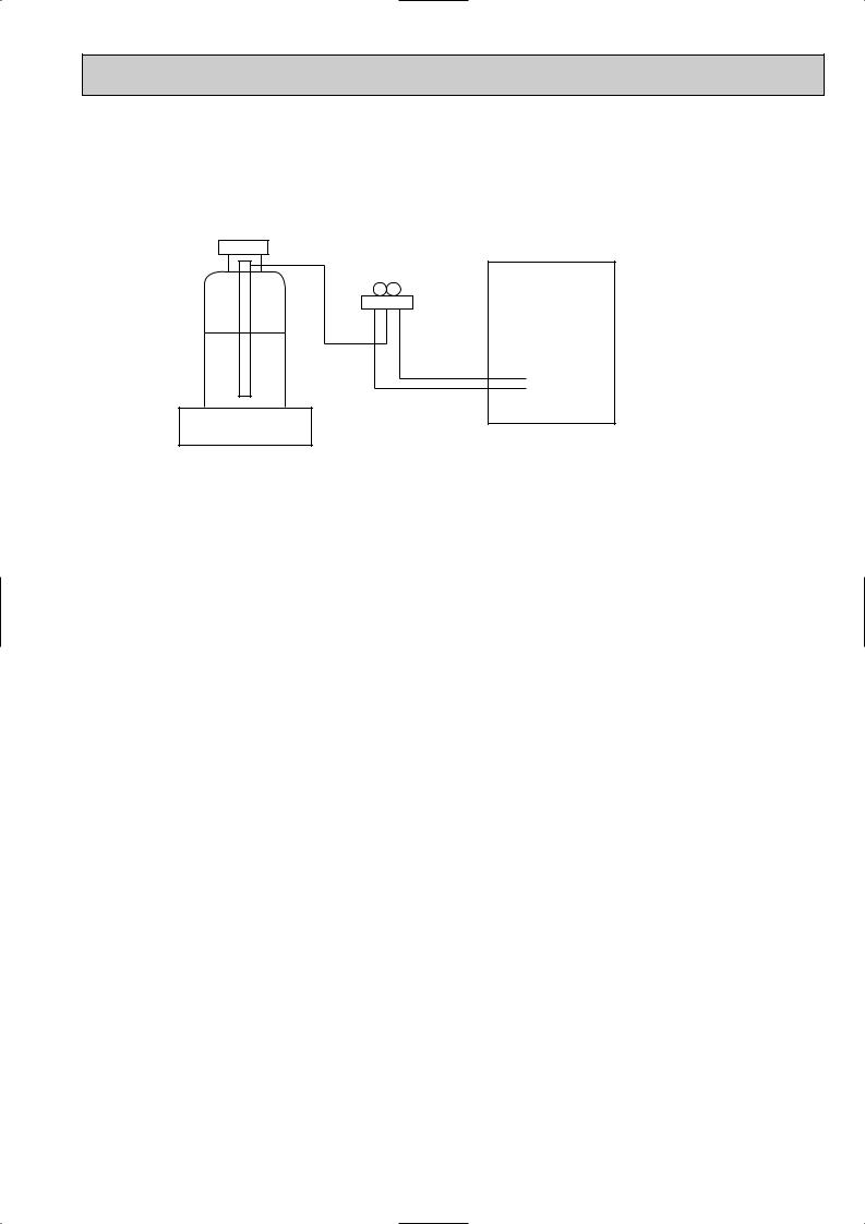
(1) Refrigerant recharging process
1Direct charging from the cylinder.
·R407C cylinder are available on the market has a syphon pipe. ·Leave the syphon pipe cylinder standing and recharge it.
(By liquid refrigerant)
Unit
Gravimeter
(2) Recharge in refrigerant leakage case
·After recovering the all refrigerant in the unit, proceed to working. ·Do not release the refrigerant in the air.
·After completing the repair service, recharge the cycle with the specified amount of liquid refrigerant.
[3] Service tools
Use the below service tools as exclusive tools for R407C refrigerant.
No. |
Tool name |
Specifications |
|
|
|
1 |
Gauge manifold |
·Only for R407C. |
|
|
|
|
|
·Use the existing fitting SPECIFICATIONS. (UNF7/16) |
|
|
|
|
|
·Use high-tension side pressure of 3.43MPa·G or over. |
|
|
|
2 |
Charge hose |
·Only for R407C. |
|
|
|
|
|
·Use pressure performance of 5.10MPa·G or over. |
|
|
|
3 |
Electronic scale |
— |
|
|
|
4 |
Gas leak detector |
·Use the detector for R134a or R407C. |
|
|
|
5 |
Adapter for reverse flow check. |
·Attach on vacuum pump. |
|
|
|
6 |
Refrigerant charge base. |
— |
|
|
|
7 |
Refrigerant cylinder. |
·For R407C ·Top of cylinder (Brown) |
|
|
·Cylinder with syphon |
|
|
|
8 |
Refrigerant recovery equipment. |
— |
|
|
|
3

Cautions for units utilizing refrigerant R410A
Do not use the existing refrigerant piping.
The old refrigerant and lubricant in the existing piping contains a large amount of chlorine which may cause the lubricant deterioration of the new unit.
Use “low residual oil piping”
If there is a large amount of residual oil (hydraulic oil, etc.) inside the piping and joints, deterioration of the lubricant will result.
Store the piping to be used during installation indoors and keep both ends of the piping sealed until just before brazing. (Leave elbow joints, etc. in their packaging.)
If dirt, dust or moisture enter into refrigerant cycle, that can cause deterioration of refrigerant oil or malfunction of compressor.
Use ester oil, ether oil or alkylbenzene oil (small amount) as the refrigerant oil applied to flares and flange connections.
If large amount of mineral oil enter, that can cause deterioration of refrigerant oil etc.
Charge refrigerant from liquid phase of gas cylinder.
If the refrigerant is charged from gas phase, composition change may occur in refrigerant and the efficiency will be lowered.
Do not use refrigerant other than R410A.
If other refrigerant (R22 etc.) is used, chlorine in refrigerant can cause deterioration of refrigerant oil etc.
Use a vacuum pump with a reverse flow check valve.
Vacuum pump oil may flow back into refrigerant cycle and that can cause deterioration of refrigerant oil etc.
Use the following tools specifically designed for use with R410A refrigerant.
The following tools are necessary to use R410A refrigerant.
|
Tools for R410A |
|
Gauge manifold |
|
Flare tool |
Charge hose |
|
Size adjustment gauge |
Gas leak detector |
|
Vacuum pump adaptor |
Torque wrench |
|
Electronic refrigerant |
|
|
charging scale |
|
|
|
Keep the tools with care.
If dirt, dust or moisture enter into refrigerant cycle, that can cause deterioration of refrigerant oil or malfunction of compressor.
Do not use a charging cylinder.
If a charging cylinder is used, the composition of refrigerant will change and the efficiency will be lowered.
Ventilate the room if refrigerant leaks during operation. If refrigerant comes into contact with a flame, poisonous gases will be released.
4
[1]Cautions for service
(1)Perform service after collecting the refrigerant left in unit completely.
(2)Do not release refrigerant in the air.
(3)After completing service, charge the cycle with specified amount of refrigerant.
(4)When performing service, install a filter drier simultaneously. Be sure to use a filter drier for new refrigerant.
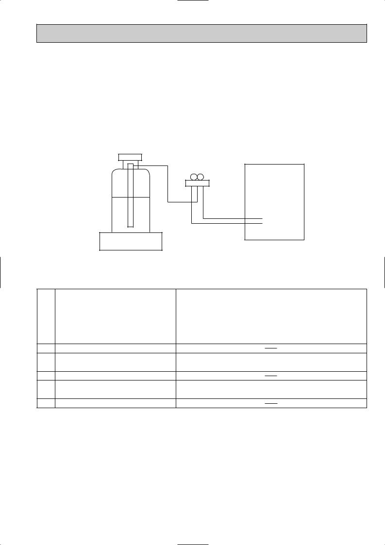
[2]Additional refrigerant charge
When charging directly from cylinder
·Check that cylinder for R410A on the market is syphon type.
·Charging should be performed with the cylinder of syphon stood vertically. (Refrigerant is charged from liquid phase.)
Unit
Gravimeter
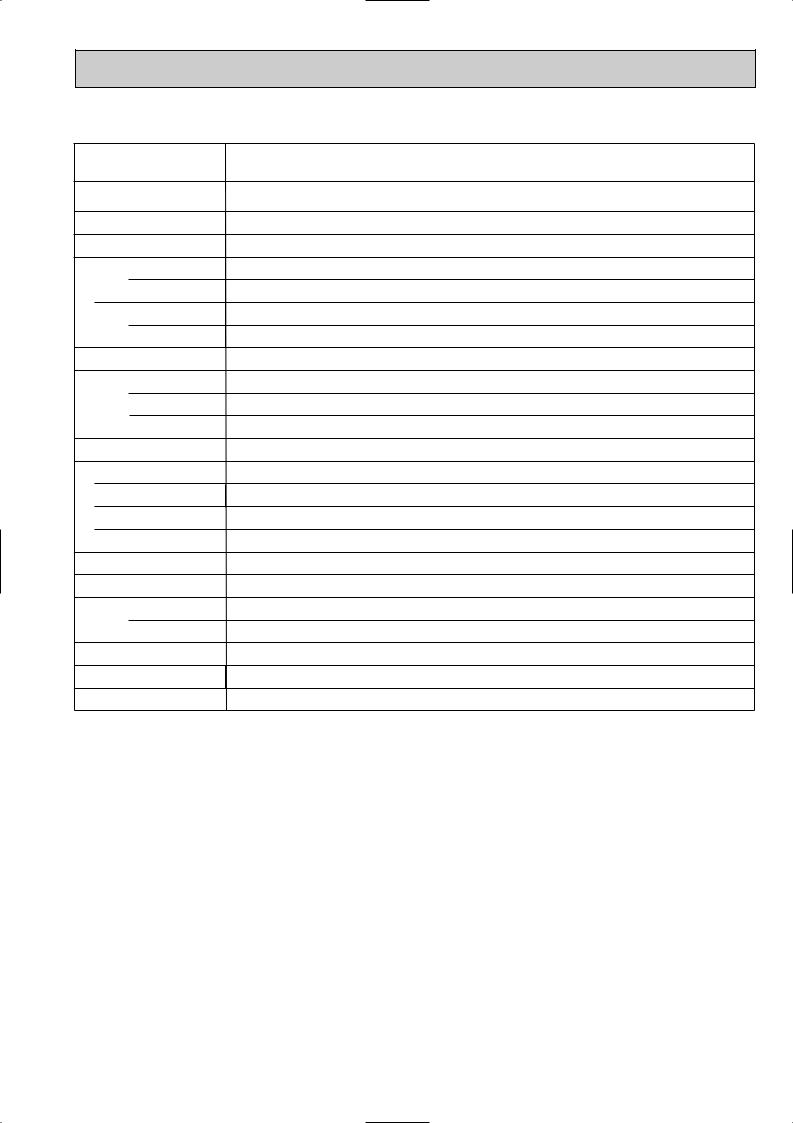
[3] Service tools
Use the below service tools as exclusive tools for R410A refrigerant.
No. |
|
Specifications |
1 |
Gauge manifold |
·Only for R410A |
|
|
|
|
|
·Use the existing fitting specifications. (UNF1/2) |
|
|
|
|
|
·Use high-tension side pressure of 5.3MPa·G or over. |
|
|
|
2 |
Charge hose |
·Only for R410A |
|
|
|
|
|
·Use pressure performance of 5.09MPa·G or over. |
3Electronic scale
4 |
Gas leak detector |
·Use the detector for R134a, R407C or R410A. |
|
|
|
5 |
Adaptor for reverse flow check |
·Attach on vacuum pump. |
6Refrigerant charge base
7 Refrigerant cylinder |
·Only for R410A |
Top of cylinder (Pink) |
|
|
Cylinder with syphon |
8Refrigerant recovery equipment
5

2 
 PART NAMES AND FUNCTIONS
● Indoor Unit
Filter
Remove dust and pollutants from return air
Horizontal Air Outlet
Sets airflow horizontal automatically during cooling or dehumidifying.
Grille
Auto Air Swing Vane Disperses airflow up and down and adjusts the angle of airflow direction.
Air Intake
Returns air from room.
● Wired remote controller
On the controls are set, the same operation mode can be repeated by simply pressing the ON/OFF button.
● Operation buttons
Set Temperature buttons |
|
|
|
Down |
|
|
|
Up |
|
|
|
Timer Menu button |
|
|
|
(Monitor/Set button) |
|
|
|
Mode button (Return button) |
|
|
|
|
|
TEMP. |
|
Set Time buttons |
|
|
|
Back |
|
MENU |
ON/OFF |
Ahead |
BACK |
MONITOR/SET |
DAY |
|
|||
Timer On/Off button |
PAR-21MAA |
CLOCK |
|
(Set Day button) |
|
|
|
Opening the |
|
|
|
door. |
|
|
|
|
|
ON/OFF button |
||
|
|
Fan Speed button |
||
|
|
Filter |
button |
|
|
|
(<Enter> button) |
||
|
ON/OFF |
Test Run button |
||
|
|
|
|
|
|
|
Check button (Clear button) |
||
|
FILTER |
|
|
|
|
CHECK |
TEST |
|
|
OPERATION |
|
Airflow Up/Down button |
||
CLEAR |
|
|
|
|
|
|
Louver button |
||
|
|
( |
|
Operation button) |
|
|
|
|
To preceding operation |
|
|
|
|
number. |
|
|
Ventilation button |
||
|
|
( |
Operation button) |
|
|
|
|
|
To next operation number. |
6
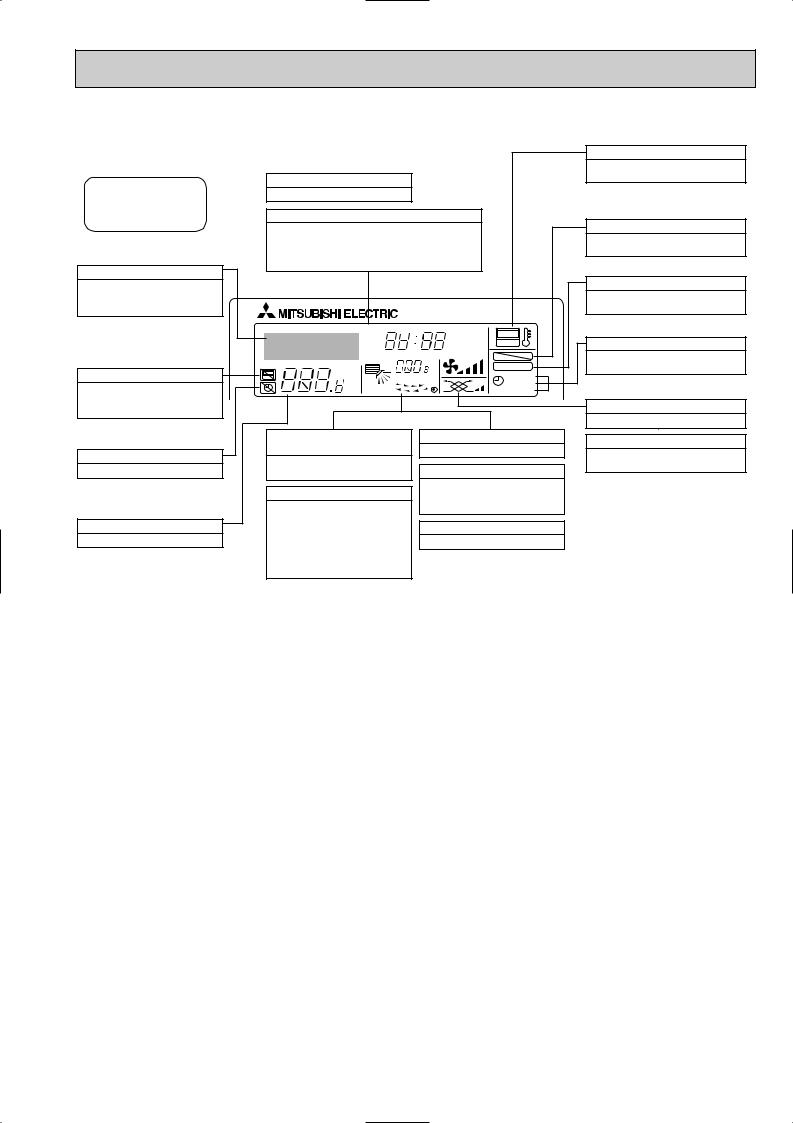
● Display
For purposes of this explanation, all parts of the display are shown as lit. During actual operation, only the relevant items will be lit.
Identifies the current operation
Shows the operating mode, etc.
*Multilanguage display is supported.
“Centrally Controlled” indicator
Indicates that operation of the remote controller has been prohibited by a master controller.
“Timer Is Off” indicator
Indicates that the timer is off.
Temperature Setting
Shows the target temperature.
Day-of-Week
Shows the current day of the week.
Time/Timer Display
Shows the current time, unless the simple or Auto Off timer is set.
If the simple or Auto Off timer is set, shows the time remaining.
TIME SUN MON TUE WED THU FRI SAT |
||
TIMER |
Hr |
ON |
AFTER |
AFTER |
OFF |
ERROR CODE |
|
FUNCTION |
˚F˚C |
|
FILTER |
˚F˚C |
|
|
|
WEEKLY |
|
ONLY1Hr. |
|
SIMPLE |
|
AUTO OFF |
|
Up/Down Air Direction indicator
The indicator  shows the direction of the outcoming airflow.
“One Hour Only” indicator
Displayed if the airflow is set to weak and downward during COOL or DRY mode. (Operation varies according to model.)
The indicator goes off after one hour, at which time the airflow direction also changes.
Room Temperature display
Shows the room temperature.
Louver display
Indicates the action of the swing louver. Does not appear if the louver is stationary.
 (Power On indicator)
Indicates that the power is on.
“Sensor” indication
Displayed when the remote controller sensor is used.
“Locked” indicator
Indicates that remote controller buttons have been locked.
“Clean The Filter” indicator
Comes on when it is time to clean the filter.
Timer indicators
The indicator comes on if the corresponding timer is set.
Fan Speed indicator
Shows the selected fan speed.
Ventilation indicator
Appears when the unit is running in Ventilation mode.
Caution
●Only the Power on indicator lights when the unit is stopped and power supplied to the unit.
●If you press a button for a feature that is not installed at the indoor unit, the remote controller will display the “Not Available” message.
If you are using the remote controller to drive multiple indoor units, this message will appear only if he feature is not present at the parent unit.
●When power is turned ON for the first time, it is normal that “PLEASE WAIT” is displayed on the room temperature indication (For max. 2minutes). Please wait until this “PLEASE WAIT” indication disappear then start the operation.
7

3 
 SPECIFICATIONS
3-1. SPECIFICATIONS
Item
|
|
Power |
V·Hz |
||
Cooling capacity |
kW |
||||
Heating capacity |
kW |
||||
characteristic |
|
Input |
|
Cooling |
kW |
|
|
||||
|
|
|
|||
|
|
|
Heating |
|
|
|
|
|
|
kW |
|
Electric |
|
Current |
|
Cooling |
A |
|
|
Heating |
A |
||
|
|
|
|
|
|
|
|
|
|
|
|
|
|
Exterior |
— |
||
(munsell symbol) |
|||||
|
|
|
|
Height |
mm |
|
|
|
|
||
Dimensions |
|
Width |
mm |
||
|
|
|
|
Depth |
mm |
Heat exchanger |
— |
||||
|
|
Fan No |
— |
||
|
|
||||
F |
|
Air flow W3 |
k/min |
||
a |
|
||||
|
External |
|
|||
n |
|
Pa |
|||
|
static pressure |
||||
|
|
Fan motor |
kW |
||
|
|
output |
|||
|
|
Insulator |
— |
||
|
|
Air filter |
— |
||
|
|
|
|
sideGas |
[mm(in.) |
|
Pipe |
|
|||
dimensions |
Liquidside |
[mm(in.) |
|||
Unit drain pipe size |
[mm |
||||
Noise level W3 |
dB |
||||
Product weight |
kg |
||||
|
|
|
|
|
|
PLFY-P32VAM-E.UK PLFY-P40VAM-E.UK PLFY-P50VAM-E.UK PLFY-P63VAM-E.UK
Single phase 220-230-240V 50Hz
Single phase 220V 60Hz
3.6 |
4.5 |
|
5.6 |
|
7.1 |
4.0 |
5.0 |
|
6.3 |
|
8.0 |
0.12 |
0.14 |
|
|
0.16 |
|
0.12 |
0.14 |
|
|
0.16 |
|
0.59 |
0.68 |
|
|
0.78 |
|
0.59 |
0.68 |
|
|
0.78 |
|
Unit : Galvanized sheets with gray heat insulation |
Grills : ABS resin |
Munsell<0.70Y 8.59/0.97> |
|||
258<30>
840<950>
840<950>
Cross fin
Turbo fan 1
14-13-12-11 |
16-14-13-12 |
18-16-15-14 |
|
|
|
0
0.070
Polyethylene sheet
|
PP honey comb fabric |
|
[12.7(1/2") |
|
[12.7(1/2") / [15.88(5/8") |
|
(Compatible) |
|
[6.35(1/4") |
|
[6.35(1/4")/[9.52(3/8") |
|
(Compatible) |
|
O.D.32 (PVC pipe VP-25 connectable)
31-29-28-27 |
32-30-28-27 |
22<5>
[15.88(5/8")
[9.52(3/8")
33-31-29-28
24<5>
Note 1. |
Rating conditions(JIS B 8616) |
|
||
|
Cooling : |
Indoor : |
D.B. 27°C |
W.B. 19.0°C |
|
|
outdoor : |
D.B. 35°C |
|
|
Heating : |
Indoor : |
D.B. 20°C |
|
|
|
outdoor : |
D.B. 7°C |
W.B. 6°C |
Note 2. |
The number indicated in < > is just for the grille. |
|||
W 3. |
Air flow and the noise level are indicated as High-Medium1-Medium2-Low. |
|||
8
Item
|
|
Power |
V·Hz |
||
Cooling capacity |
kW |
||||
Heating capacity |
kW |
||||
characteristic |
|
Input |
|
Cooling |
kW |
|
|
||||
|
|
|
|||
|
|
|
Heating |
|
|
|
|
|
|
kW |
|
Electric |
|
Current |
|
Cooling |
A |
|
|
Heating |
A |
||
|
|
|
|
|
|
|
|
|
|
|
|
|
|
Exterior |
— |
||
(munsell symbol) |
|||||
|
|
|
|
Height |
mm |
|
|
|
|
||
Dimensions |
|
Width |
mm |
||
|
|
|
|
Depth |
mm |
Heat exchanger |
— |
||||
|
|
Fan No |
— |
||
|
|
||||
F |
|
Air flow W3 |
k/min |
||
a |
|
||||
|
External |
|
|||
n |
|
Pa |
|||
|
static pressure |
||||
|
|
Fan motor |
kW |
||
|
|
output |
|||
|
|
Insulator |
— |
||
|
|
Air filter |
— |
||
|
|
|
|
sideGas |
[mm(in.) |
|
Pipe |
|
|||
dimensions |
Liquidside |
[mm(in.) |
|||
Unit drain pipe size |
[mm |
||||
Noise level W3 |
dB |
||||
Product weight |
kg |
||||
|
|
|
|
|
|
PLFY-P80VAM-E.UK |
PLFY-P100VAM-E.UK |
|
PLFY-P125VAM-E.UK |
|
|
|
|
|
Single phase 220-230-240V 50Hz |
|
|
|
Single phase 220V 60Hz |
|
|
9.0 |
11.2 |
|
14.0 |
10.0 |
12.5 |
|
16.0 |
0.18 |
0.30 |
|
0.34 |
0.18 |
0.30 |
|
0.34 |
0.86 |
1.43 |
|
1.64 |
0.86 |
1.43 |
|
1.64 |
|
|
|
|
Unit : Galvanized sheets with gray heat insulation Grills : ABS resin |
Munsell<0.70Y 8.59/0.97> |
|||
258<30> |
|
298<30> |
|
|
|
840<950> |
|
|
|
|
840<950> |
|
|
|
|
|
Cross fin |
|
|
|
|
Turbo fan 1 |
|
|
22-20-18-16 |
|
|
29-27-24-21 |
|
|
27-25-22-19 |
|
||
|
0 |
|
|
|
0.070 |
|
|
|
|
|
0.120 |
|
||
|
|
Polyethylene sheet |
|
|
|
|
PP honey comb fabric |
|
|
15.88(5/8") |
|
|
||
|
[15.88(5/8") / [19.05(3/4") |
|||
|
(Compatible) |
|
||
|
9.52(3/8") |
|
|
|
|
O.D.32 (PVC pipe VP-25 connectable) |
|
||
37-35-32-30 |
|
|
43-41-38-35 |
|
|
41-39-36-33 |
|
||
24<5> |
|
32<5> |
|
|
|
|
|
|
|
Note 1. |
Rating conditions(JIS B 8616) |
|
||
|
Cooling : |
Indoor : |
D.B. 27°C |
W.B. 19.0°C |
|
|
outdoor : |
D.B. 35°C |
|
|
Heating : |
Indoor : |
D.B. 20°C |
|
|
|
outdoor : |
D.B. 7°C |
W.B. 6°C |
Note 2. |
The number indicated in < > is just for the grille. |
|||
W 3. |
Air flow and the noise level are indicated as High-Medium1-Medium2-Low. |
|||
9
3-2. ELECTRICAL PARTS SPECIFICATIONS
Model |
Symbol PLFY-P32VAM-E.UK PLFY-P40VAM-E.UK PLFY-P50VAM-E.UK PLFY-P63VAM-E.UK |
|||
|
||||
Parts name |
|
|
|
|
Room temperature |
TH21 |
Resistance 0:/15k", 10:/9.6k", 20:/6.3k", 25:/5.4k", 30:/4.3k", 40:/3.0k" |
||
thermistor |
||||
|
|
|
||
Liquid pipe thermistor |
TH22 |
Resistance 0:/15k", 10:/9.6k", 20:/6.3k", 25:/5.4k", 30:/4.3k", 40:/3.0k" |
||
Gas pipe thermistor |
TH23 |
Resistance 0:/15k", 10:/9.6k", 20:/6.3k", 25:/5.4k", 30:/4.3k", 40:/3.0k" |
||
Fuse |
FUSE |
|
250V 6.3A |
|
(Indoor controller board) |
|
|||
|
|
|
||
|
|
|
6-pole OUTPUT 70W |
|
Fan motor |
MF |
|
D17B6P70MS |
|
|
|
|||
(with inner-thermostat) |
|
OFF 130: i 5: |
||
|
Inner-thermostat |
|||
|
|
|||
|
|
ON 90: i 20: |
||
|
|
|
||
Fan motor capacitor |
C |
|
3.0+ 440V |
|
Vane motor |
MV |
|
MSBPC20M04 |
|
|
DC12V 300"/phase |
|||
|
|
|
||
Drain-up mechanism |
DP |
|
PLD-12230ME-1 |
|
INPUT 12/10.8W 24R/Hr |
||||
|
|
|||
Drain sensor |
DS |
Thermistor resistance 0:/6k", 10:/3.9k", 20:/2.6k", 25:/2.2k", 30:/1.8k", 40:/1.3k" |
||
Linear expansion valve |
LEV |
DC12V Stepping motor drive port dimension 5.2" (0~2000pulse) |
||
|
EDM-40YGME |
|||
|
|
|
||
Electric heater |
H2 |
|
240V 21.8W |
|
(Condensation proof) |
|
|||
|
|
|
||
Power supply terminal |
TB2 |
(L, N, ;) Rated to 330V 30A W |
||
block |
||||
|
|
|
||
Transmission terminal |
TB5 |
(M1, M2, S) Rated to 250V 20A W |
||
block |
||||
|
|
|
||
MA remote controller |
TB15 |
(1, 2) Rated to 250V 10A W |
||
terminal block |
||||
|
|
|
||
W Note : Refer to WIRING DIAGRAM for the supplied voltage.
10
Model |
Symbol |
PLFY-P80VAM-E.UK |
PLFY-P100VAM-E.UK |
PLFY-P125VAM-E.UK |
||
|
||||||
Parts name |
|
|
|
|
|
|
Room temperature |
TH21 |
Resistance 0:/15k", 10:/9.6k", 20:/6.3k", 25:/5.4k", 30:/4.3k", 40:/3.0k" |
||||
thermistor |
||||||
|
|
|
|
|
||
Liquid pipe thermistor |
TH22 |
Resistance 0:/15k", 10:/9.6k", 20:/6.3k", 25:/5.4k", 30:/4.3k", 40:/3.0k" |
||||
Gas pipe thermistor |
TH23 |
Resistance 0:/15k", 10:/9.6k", 20:/6.3k", 25:/5.4k", 30:/4.3k", 40:/3.0k" |
||||
Fuse |
FUSE |
|
250V 6.3A |
|
||
(Indoor controller board) |
|
|
||||
|
|
|
|
|
||
|
|
6-pole OUTPUT 70W |
|
6-pole OUTPUT 120W |
||
Fan motor |
MF |
D17B6P70MS |
|
D176P120MS |
||
|
|
|
|
|||
(with inner-thermostat) |
|
|
OFF 130: i 5: |
|||
|
Inner-thermostat |
|||||
|
|
|||||
|
|
ON 90: i |
20: |
|||
|
|
|
|
|||
Fan motor capacitor |
C |
3.5+ 440V |
|
7.0+ 440V |
||
Vane motor |
MV |
|
MSBPC20M04 |
|
||
|
DC12V 300"/phase |
|
||||
|
|
|
|
|||
Drain-up mechanism |
DP |
|
PLD-12230ME-1 |
|
||
|
INPUT 12/10.8W 24R/Hr |
|||||
|
|
|
||||
Drain sensor |
DS |
Thermistor resistance 0:/6k", 10:/3.9k", 20:/2.6k", 25:/2.2k", 30:/1.8k", 40:/1.3k" |
||||
Linear expansion valve |
LEV |
DC12V Stepping motor drive port dimension 5.2" (0~2000pulse) |
||||
|
EDM-80YGME |
|
||||
|
|
|
|
|||
Electric heater |
H2 |
|
240V 21.8W |
|
||
(Condensation proof) |
|
|
||||
|
|
|
|
|
||
Power supply terminal |
TB2 |
|
(L, N, ;) Rated to 330V 30A W |
|||
block |
|
|||||
|
|
|
|
|
||
Transmission terminal |
TB5 |
|
(M1, M2, S) Rated to 250V 20A W |
|||
block |
|
|||||
|
|
|
|
|
||
MA remote controller |
TB15 |
|
(1, 2) Rated to 250V 10A W |
|||
terminal block |
|
|||||
|
|
|
|
|
||
W Note : Refer to WIRING DIAGRAM for the supplied voltage.
4 4-WAY AIR FLOW SYSTEM
4-1. PLACEMENT OF THE AIR OUTLETS
•For this grille, the blowout direction comes in 11 patterns.
Also, by setting the dip switches (SWA and SWB) on the circuit board to the appropriate settings, you can adjust the air flow and speed. Select the settings from Table according to the location in which you want to install the unit.
1) Decide on the pattern of the airflow direction.
<Table 1> |
4-direction |
3-direction |
directionBlowout pattern |
Pattern 1 Factory setting |
Pattern 4 One air outlet |
|
fully closed |
|
|
|
|
|
|
|
|
|
|
|
|
2-direction |
Note1. |
||||||||
|
|
|
|
|
|
|
|
|
|
|
|
|
|
|
|
|
|
For 3 and 2-directional, |
|
|
|
|
Pattern 6 |
Two air outlet |
please use the air outlet |
||||||||||||
|
|
|
|
|
|
|
|
|
fully closed |
shutter plate (option). |
||||||||
|
|
|
|
|
|
|
|
|
|
|
|
|
|
|
|
|
|
|
|
|
|
|
|
|
|
|
|
|
|
|
|
|
|
|
|
|
|
|
|
|
|
|
|
|
|
|
|
|
|
|
|
|
|
|
|
|
|
|
|
|
|
|
|
|
|
|
|
|
|
|
|
|
|
|
|
|
|
|
|
|
|
|
|
|
|
|
|
|
|
|
|
|
|
|
|
|
|
|
|
|
|
|
|
|
|
|
|
|
|
|
|
|
|
|
|
|
|
|
|
|
|
|
|
|
|
|
|
|
|
|
|
|
|
|
|
|
|
|
|
|
|
|
|
|
|
|
|
|
|
|
|
|
|
|
|
|
|
|
|
|
|
|
|
|
|
|
|
|
|
|
|
|
|
|
|
|
|
|
|
|
|
|
|
|
|
|
|
|
|
|
|
|
|
|
|
|
|
|
|
|
|
|
|
|
|
|
|
|
11
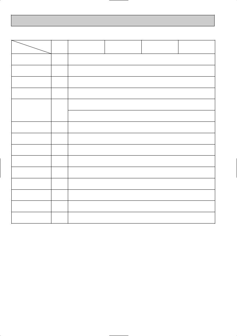
2) According to the number of air outlets and height of the ceiling to install the unit, be sure to set the up switches (SWA, SWB) on the circuit board to the appropriate setting.
• Correspondence of ceiling heights to numbers of air outlets.
-P32·P40·P50·P63·P80VAM-E |
|
||
SWA |
1 |
2 |
3 |
|
Standard |
High ceiling 1 High ceiling 2 |
|
direction |
2.7m |
3.0m |
3.5m |
direction |
3.0m |
3.3m |
3.5m |
direction |
3.3m |
3.5m |
— |
-P100·P125VAM-E |
|
|
|
SWA |
1 |
2 |
3 |
|
Standard |
High ceiling 1 High ceiling 2 |
|
direction |
3.2m |
3.6m |
4.2m |
direction |
3.6m |
4.0m |
4.2m |
direction |
4.0m |
4.2m |
— |
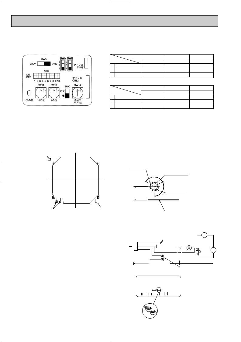
4-2. FRESH AIR INTAKE (Installation of site)
•At the time of installation, use the duct holes (cutout) located at the positions shown in following diagram, as and when required.
Note :
Be sure to add135mm to the dimensions in the diagram that are marked with a “w” if installing a multi function casement (Option)
Fresh air intake hole
Fresh air intake hole diagram
3 - {2.8 Burring hole
120_
w158
Refrigerant pipe |
Drain pipe |
_ 120
4-3. INTERLOCKING OPERATION METHOD WITH DUCT FAN (Booster fan)
•Whenever the indoor unit is operating, the duct fun also operates.
(1)Connect the optional multiple remote controller adapter(PAC-SA88HA-E)to the connector CN51 on the indoor controller board.
(2)Drive the relay after connecting the 12V DC relay between the Yellow and Orange connector lines.
MB: Electromagnetic switch power relay for duct fan.
X:Auxiliary relay (For DC 12V, coil rating : 1.0W or below)
CN51 |
5 |
Green |
|
|
on |
|
|
Yellow |
|
indoor |
|
|
|
|
controller |
1 |
|
Orange |
MB |
board |
Connector (5P) |
Red |
|
|
|
Package side |
Brown |
|
|
|
Multiple remote |
Installation at site |
||
|
|
|
||
|
|
|
|
|
|
|
|
controller adapter |
Be sure to secure insulation |
Indoor controller board |
|
PAC-SA88HA-E |
material by tape and such |
|
|
|
|
||
|
|
|
|
Distance between indoor |
|
|
|
CN51 |
controller board and relay |
|
|
|
must be within 10m. |
|
Multiple remote controller adapter PAC-SA88HA-E
CN51
12
 Loading...