


PKFY-P32VGM
TECHNICAL & SERVICE MANUAL
SPLIT-TYPE,HEAT PUMP AIR CONDITIONERS
CONTENTS
1. SAFETY PRECAUTION ·····························2
2. PART NAMES AND FUNCTIONS ·············4
3. SPECIFICATIONS······································6
4. OUTLINES AND DIMENSIONS ·················8
5. WIRING DIAGRAM ····································9
6. REFRIGERANT SYSTEM DIAGRAM······10
7. TROUBLE SHOOTING ····························11
8. DISASSEMBLY PROCEDURE················16
9. PARTS LIST·············································19
<Indoor unit>
PKFY-P32VGM
PKFY-P40VGM
PKFY-P50VGM
No. OC179
1998
[ Model names ]
Wall Mounted
Series PKFY
Indoor unit
R407C/R22
[ Service Ref. ]
PKFY-P32VGM
PKFY-P40VGM
PKFY-P50VGM

2
1
SAFETY PRECAUTION
Cautions for using with the outdoor unit which adopts R407C refrigerant.
· Do not use the existing refrigerant piping.
-The old refrigerant and refrigerator oil in the existing piping contains a large amount of chlorine which may cause the
refrigerator oil of the new unit to deteriorate.
· Use “low residual oil piping”.
-If there is a large amount of residual oil (hydraulic oil, etc.) inside the piping and joints, deterioration of the refrigerator oil
will result.
· Store the piping to be used during installation indoors and keep both ends of the piping sealed until just before
brazing. (Store elbows and other joints in a plastic bag.)
-If dust, dirt, or water enters the refrigerant cycle, deterioration of the oil and compressor trouble may result.
· Use ESTR , ETHER or HAB as the refrigerator oil to coat flares and flange connection parts.
Use liquid refrigerant to seal the system.
-If gas refrigerant is used to seal the system, the composition of the refrigerant in the cylinder will change and performance
may drop.
· Do not use a refrigerant other than R407C.
-If another refrigerant (R22, etc.) is used, the chlorine in the refrigerant may cause the refrigerator oil to deteriorate.
· Use a vacuum pump with a reverse flow check valve.
-The vacuum pump oil may flow back into the refrigerant cycle and cause the refrigerator oil to deteriorate.
3
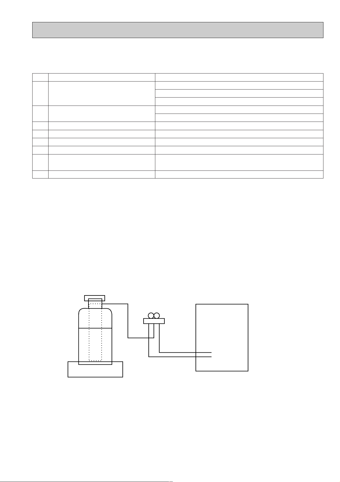
[3] Refrigerant recharging
(1) Refrigerant recharging process
1Direct charging from the cylinder.
·R407C cylinder are available on the market has a syphon pipe.
·Leave the syphon pipe cylinder standing and recharge it.
(By liquid refrigerant)
(2) Recharge in refrigerant leakage case
·After recovering the all refrigerant in the unit, proceed to working.
·Do not release the refrigerant in the air.
·After completing the repair service, recharge the cycle with the specified amount of
liquid refrigerant.
Gravimeter
Unit
[1] Service tools
Use the below service tools as exclusive tools for R407C refrigerant.
No. Tool name Specifications
1 Gauge manifold ·Only for R407C.
·Use the existing fitting SPECIFICATIONS. (UNF7/16)
·Use high-tension side pressure of 3.43MPa·G or over.
2 Charge hose ·Only for R407C.
·Use pressure performance of 5.10MPa·G or over.
3 Electronic scale
4 Gas leak detector ·Use the detector for R134a or R407C.
5 Adapter for reverse flow check. ·Attach on vacuum pump.
6 Refrigerant charge base.
7 Refrigerant cylinder. ·For R407C ·Top of cylinder (Brown)
·Cylinder with syphon
8 Refrigerant recovery equipment.
[2] Notice on repair service
·After recovering the all refrigerant in the unit, proceed to working.
·Do not release refrigerant in the air.
·After completing the repair service, recharge the cycle with the specified amount of
liquid refrigerant.
4
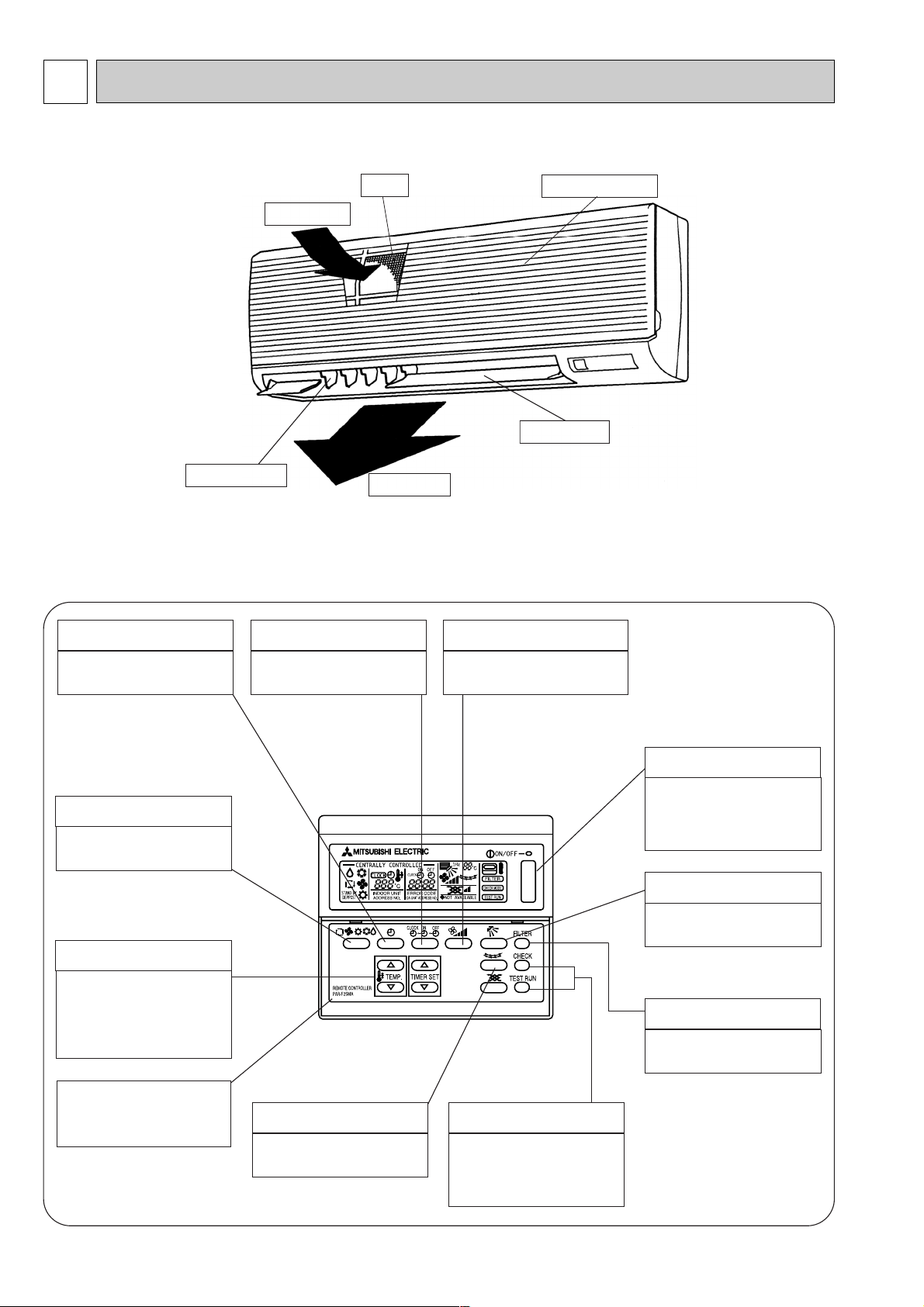
PART NAMES AND FUNCTIIONS
2
● Indoor Unit
PKFY-P32VGM
PKFY-P40VGM
PKFY-P50VGM
● Remote controller [PAR-F25MA]
● Once the controls are set, the same operation mode can be repeated by simply pressiry the on / off button.
TIMER button
This switches between continuous
operation and the timer operation
AIR SPEED button
The sets the ventilation fan speed.
● Operation buttons
TIME SETTING button
This sets or switches the current
time, start time and stop time.
OPERATION SWITCH button
Press this button to switch the cooler
electronic dry (denumidity),
automatic and heater modes.
TEMP ADJUSTMENT button
This sets the room temperature. The
temperature setting can be
performed in 1°C units.
Setting range :
Cooler 19°C to 30°C
Heater 17°C to 28°C
CHECK-TEST RUN button
Only press this button to perform an
inspection check or test operation.
Do not use it for nomal operation
FILTER button
This resets the filter service
indication display
AIR DIRECTION button
This adjusts the vertical angle of the
ventilation.
ON/OFF button
This switches between the operation
and stop modes each time it is
pressed. The lamp on this button
lights during operation.
The model name of the remote
controller is indicated.
LOUVER button
This switches the horizontal fan
motion ON and OFF.
(This button does not operate in this
model.)
Air intake
Air intake gril
Filter
Air outlet
Guide vane
Auto vane
5
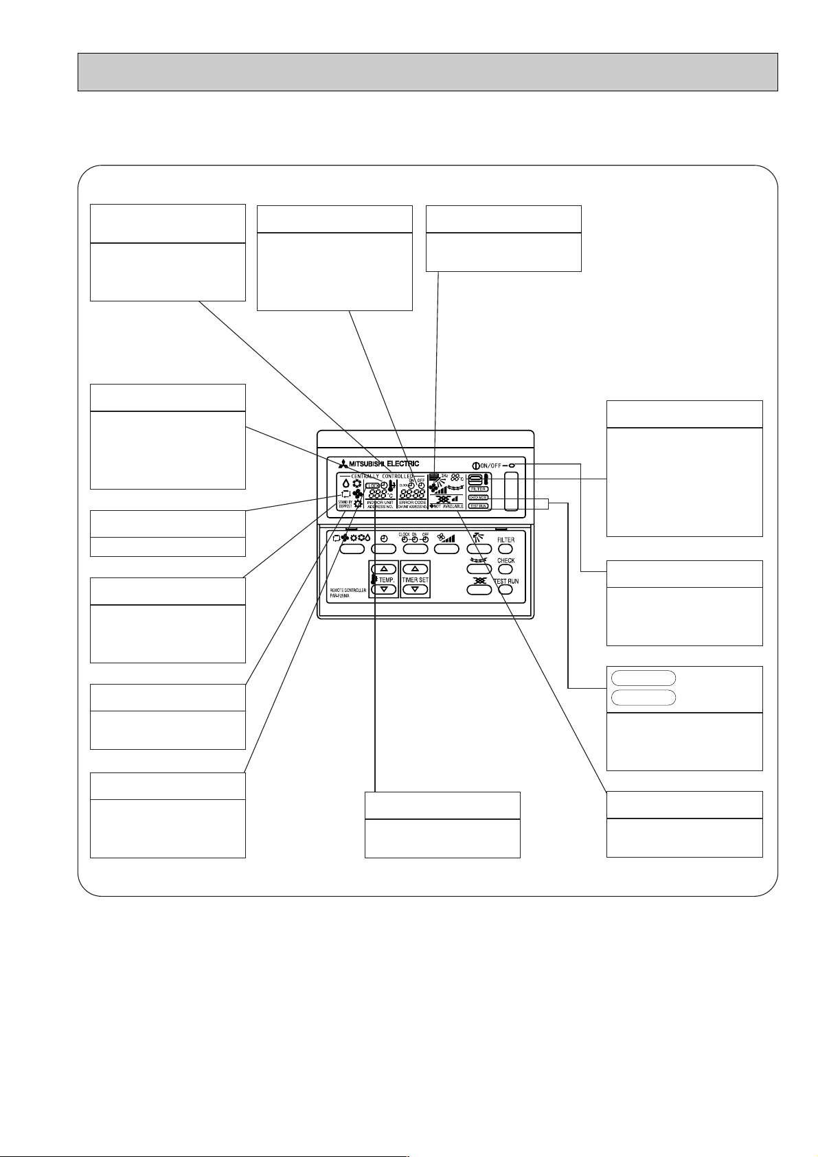
Caution
● Only the Power display lights when the unit is stopped and power supplied to the unit.
● When power is turned ON for the first time the (CENTRAL CTRL) display appears to go off momentarily but this is not a
malfunction.
● When the central control remote control unit, which is sold separately, is used the ON-OFF button, Operation switch button
and i TEMP button do not operate.
● “NOT AVAILABLE” is displayed when the Air speed button and the Louver button are pressed.This indicates that this room unit
is not equipped with the fan direction adjustment function and the louver function.
● When power is turned ON for the first time, it is normal that “ HO ” is displayed on the room temperature indication (For max.
2 minutes).Please wait until this “ HO ” indication disapear then start the operation.
CENTRALLY
CONTROLLED display
This indicates when the unit is
controlled by optional features such
as central control type remote
controller.
TIMER display
This indicates when the continuous
operation and time operation modes
are set.
It also display the time for the timer
operation at the same time as when
it is set.
OPERATION MODE display
This indicates the operation mode.
STANDBY display
This indicates when the standby
mode is set from the time the sleep
operation starts until the heating air
is discharged.
DEFROST display
This indicates when the defrost
operation is performed.
CHECK display
This indicates when a malfunction
has occurred in the unit which should
be checked.
POWER display
This display lights when the filter
need to be cleaned.
SET TEMPERATURE display
This displays the selected setting
temperature.
CLOCK display
The current time , start time and stop
time can be displayed in tensecond
intervals by pressing the time switch
button. The start time or stop time is
always displayed during the timer
operation.
FAN SPEED display
The selected fan speed is displayed.
● Display
In this display example on the
bottom left, a condition where
all display lamps light is
shown for explanation
purposes although this differs
from actual operation.
display
This display lights in the check mode
or when a test operation is
performed.
CHECK MODE
TEST RUN
ROOM TEMPERATURE display
The temperature of the suction air is
displayed during operation. The
display range is 8° to 39°C. The
display flashes 8°C when the actual
temperature is less than 8° and
flashes 39°C when the actual
temperature is greater than 39°C.
Operation lamp
This lamp lights during operation,
goes off when the unit stops and
flashes when amalfunction occurs.
6
3
SPECIFICATIONS
3-1 Specification
12 - 11 - 10 - 9
15.88 <5/8">
9.52 <3/8">
43 - 40 - 37 - 34
Power
consumption
Current
Type ✕ No.
Air flow w2
External stafic pressure
Fan motor output
Item
Power source
Cooling capacity
Heating capacity
Exterior <munsell symbol>
Dimensions
Heat exchanger
Fan
Air filter
Refrigerant
Pipe dimensions
Drain pipe dimension
Noise level w2
Product weight
Unit
V · Hz
kcal/h
kcal/h
kW
kW
A
A
—
mm
mm
mm
—
—
k/min
Pa
kW
—
[mm
[mm
[mm
dB (A)
kg
Cooling
Heating
Cooling
Heating
Height
Width
Depth
Gas side
Liquid side
PKFY-P32VGM
3150
3550
PKFY-P40VGM
4000
4500
Single phase 220-240V 50Hz
0.07
0.07
0.32
0.32
Plastic , white : <0.70Y 8.59/0.97>
340
990
235
Cross fin(Aluminum plate fin and copper tube)
Lineflow fan ✕ 1
0
0.03
PP Honey comb
Outer dimeter 20 <PVC pipe VP-20 connectable>
16
Electric
characteristic
PKFY-P50VGM
5000
5600
11.5 - 10.5 - 9.5 - 8
12.7 <1/2">
6.35 <1/4">
41 - 38 - 36 - 33
Note : w1. Rating conditions
Cooling : Indoor 27°C DB. 19.5°C WB
Outdoor 35°C DB. 24°C WB
Heating : Indoor 21°C DB.
Outdoor 7°C DB. 6°C WB
W2. Air flow and the noise level are indicated as High - Middium1 - Middium2 - Low .

7
3-2 Electrical parts specifications
Transformer
Room temperature thermistor
Liquid pipe thermistor
Gas pipe thermistor
Fuse
(Indoor controller board)
Fan motor
(with inner-thermostat)
Fan motor capacitor
Vane motor
Linear expansion valve
Power supply terminal block
Transmission terminal block
Symbol
T
TH21
TH22
TH23
FUSE
MF
C1
MV
LEV
TB2
TB5
PKFY-P32VGM
PKFY-P40VGM
(Primary) 50/60Hz 220 - 240V (Secondary) 18.4V 1.7A
Resistance
0$C/15k1, 10$C/9.6k1, 20$C/6.3k1, 25$C/5.4k1, 30$C/4.3k1, 40$C/3.0k1
250V 6.3A
PM4V30-K 220-240V/220V , 50/60Hz
4 pole Output 30W
OFF 125(5;
2.0+F 440V
MP 35 EA DC12V
DC12V Stepping motor drive
Port dimension [3.2 (0 ~ 2000pulse)
(L, N, ;) 330V 30A
(M1, M2, S) 250V 20A
Model
Parts name
PKFY-P50VGM
Inner-thermostat
 Loading...