

<REVISED>

CONTENTS
. Advantage of New MA Remote Controller ...........................................................................2
!
eekly Timer ......................................................................................................................2
1. W
2. Easy
3. New
4. The Other Functions ...........................................................................................................3
. New Functions .......................................................................................................................4
@
. Appearance ............................................................................................................................5
#
1. Display
2. Operation
. Easy
$
1. Maintenance
2. Guide
. How to Select Functions of remote controller ....................................................................9
%
1. Function
2. Flowchart
3. Screen Structure for Function Setting ............................................................................... 11
4. Function
. Unit Function Setting by the Remote Controller (for Mr. SLIM) ...................................... 38
^
. Test Run by the Remote Controller (for Mr. SLIM) ...........................................................42
&
1. Check
2. Test
. Self-Diagnosis
*
1.
2. Error Code List .................................................................................................................. 46
. Monitoring
(
1. How
2. Request
. System Control (for Mr. SLIM) ............................................................................................58
)
1. 1-Remote
2. 2-Remote Controller Operation ......................................................................................... 61
3. Group Control Operation (Collective Operation and Control of Multiple Refrigerant
4. Rotation
(
. External Dimensions ........................................................................................................... 66
Maintenance Function (Only for PUHZ type) .............................................................2
Display ........................................................................................................................3
3.1 Dot Liquid Crystal Display (LCD) ........................................................................................................................ 3
3.2 Multi-language Display .......................................................................................................................................3
4.1 Temperature Range Limit Setting .......................................................................................................................3
4.2 Auto Off Timer ..................................................................................................................................................... 3
4.3 Simple
Operation Lock .......................................................................................................................................3
Section ...................................................................................................................5
Section ...............................................................................................................5
Maintenance Function (Only for Mr. SLIM PUHZ series) ..........................................6
Mode Operating Method ................................................................................ 6
for Operation Condition ............................................................................................8
Check Points ............................................................................................................................................................... 8
Items ....................................................................................................................9
of Function Setting ...........................................................................................10
Setting Mode ......................................................................................................12
4.1 Change Language ............................................................................................................................................ 12
4.2 Function Setting ................................................................................................................................................ 14
4.2.1 Operation Lock (Operation Function Limit Setting) ............................................................................... 14
4.2.2 Auto Mode Setting
4.2.3 T
emperature Range Limit Setting.......................................................................................................... 18
4.3 Basic
4.4 Display
Functions Setting .................................................................................................................................... 20
4.3.1 Remote
4.3.2 Timer
4.3.3 Contact Number Setting for Error Situation
4.4.1 T
4.4.2 Room T
4.4.3 Automatic
Controller Main/Sub Setting..................................................................................................... 20
function setting (Weekly timer/Auto off timer/Simple timer) ........................................................21
Change Setting .................................................................................................................................... 35
emperature Display °C/°F Setting .......................................................................................................35
emperature Display Setting ......................................................................................................36
................................................................................................................................. 16
........................................................................................... 33
Cooling/Heating Display Setting .......................................................................................... 37
Points Under Test Run ...........................................................................................42
Run using the Wired Remote Controller .................................................................... 42
by the Remote Controller (for Mr. SLIM) ..................................................44
How to Proceed “Self-diagnosis” .......................................................................................44
1.1 When a Problem Occurs During Operation ...................................................................................................... 44
1.2 Self-Diagnosis During Maintenance or Service ................................................................................................ 44
1.3 Remote
Controller Diagnosis ............................................................................................................................ 45
the Operation Data by the remote Controller (for Mr. SLIM) ........................48
to “Monitor the Operation Data” ................................................................................48
Code List ............................................................................................................49
2.1 Detail Contents in Request Code .....................................................................................................................53
Controller (Standard) Operation .......................................................................60
1.1 1 Wired Remote Controller ............................................................................................................................... 60
1.2 Wireless Remote Controller .............................................................................................................................. 60
2.1 2 Wired Remote Controllers .............................................................................................................................61
2.2 2 Wireless Remote Controllers ......................................................................................................................... 61
2.3 1 Wired and 1 Wireless Remote Controller ......................................................................................................61
Systems (2 to 16)) .............................................................................................................62
function (and back-up function, 2nd stage cut-in function) ................................ 63
4.1 Operation ..........................................................................................................................................................63
4.2 How to set rotation function(back-up function, 2nd stage cut-in function) ........................................................ 64
. Advantage of New MA
!
Remote Controller
. New Functions
@
. Appearance
#
Easy Maintenance Function
.
$
(For Mr. SLIM PUHZ series)
How to Select Functions
.
%
of remote controller
Unit Funct ion Settin g by the
.
^
Remote Controller (for Mr. SLIM)
Test Run by the Remote
.
&
Controller (for Mr. SLIM)
Self-Diagnosis by the Remote
.
*
Controller (for Mr. SLIM)
Monitoring the Operation Data by
.
(
the remote Controller (for Mr. SLIM)
. System Control
)
(for Mr.SLIM)
(
. External Dimensions
1
Displays the contact number
in case of abnormality.
Displayed
alternately
Telephone number
registered in advance
Conventional
remote controller
Schedule
remote controller
Deluxe
remote controller
Saves you money
and space because
you need only one
remote controller.
26
25
24
23
22
0
10
12 14 16 18 20 22 24 (H)
1
3 5
6 7
Set the
temperature high.
*Joint research with Japan Facility Solutions, Inc.
Busy
hours
Quiet
hours
Set the
temperature low.
Preset temperature (°C)
Start of daily business
End of daily business
Lunch time
Dinner time
Seven patterns can be set.
. Advantage of New MA Remote Controller
!
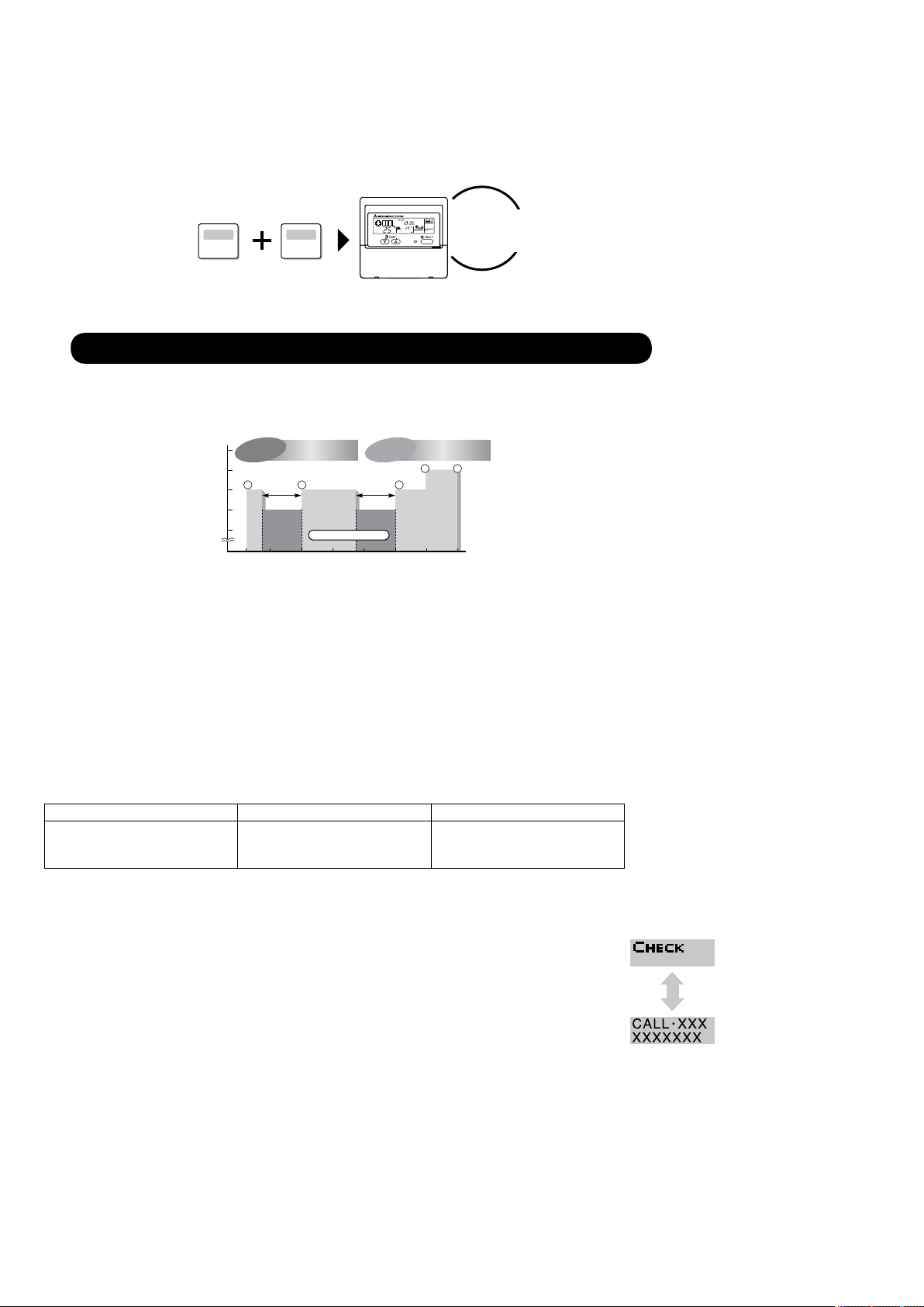
1. Weekly Timer
The built-in weekly timer enables you not only to make on/off settings but also temperature settings. Up to 8 patterns can
be set for each day of the week.
Setting example (Restaurant in summer)
Economical operation according to air conditioner use
2. Easy Maintenance Function (Only for PUHZ type)
Enables you to check necessary data on site, drastically reducing the time required for maintenance work.
Information useful for maintenance can be displayed on the remote controller.
Outdoor unit information can be checked even from inside a building.
Furthermore, use of maintenance stable-operation control that xes the operating frequency, allows smooth inspection, even for
inv
erter models.
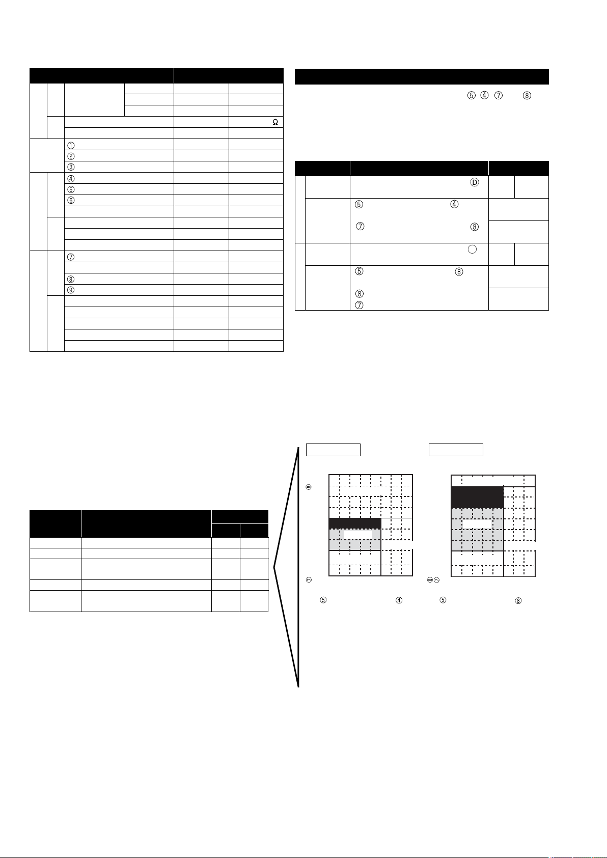
<Display information> Outputs data for nine items.
Compressor information Outdoor unit information Indoor unit information
• Accumulated operating time
• Number of ON/OFF times
• Operating current
The contact telephone
error occurs is displayed automatically.
This helps smooth contact with appropriate personnel when an error occurs.
The contact telephone number of the maintenance company to be called when an error occurs can be registered in advance. When an error occurs, the contact telephone
number will automatically appear, allowing you to call without difficult .
• Heat exchanger temperature
• Dis
charge temperature
• Outside air temperature
• Heat exchanger temperature
• Room temperature
• Filter operating time
number to be called when an
2
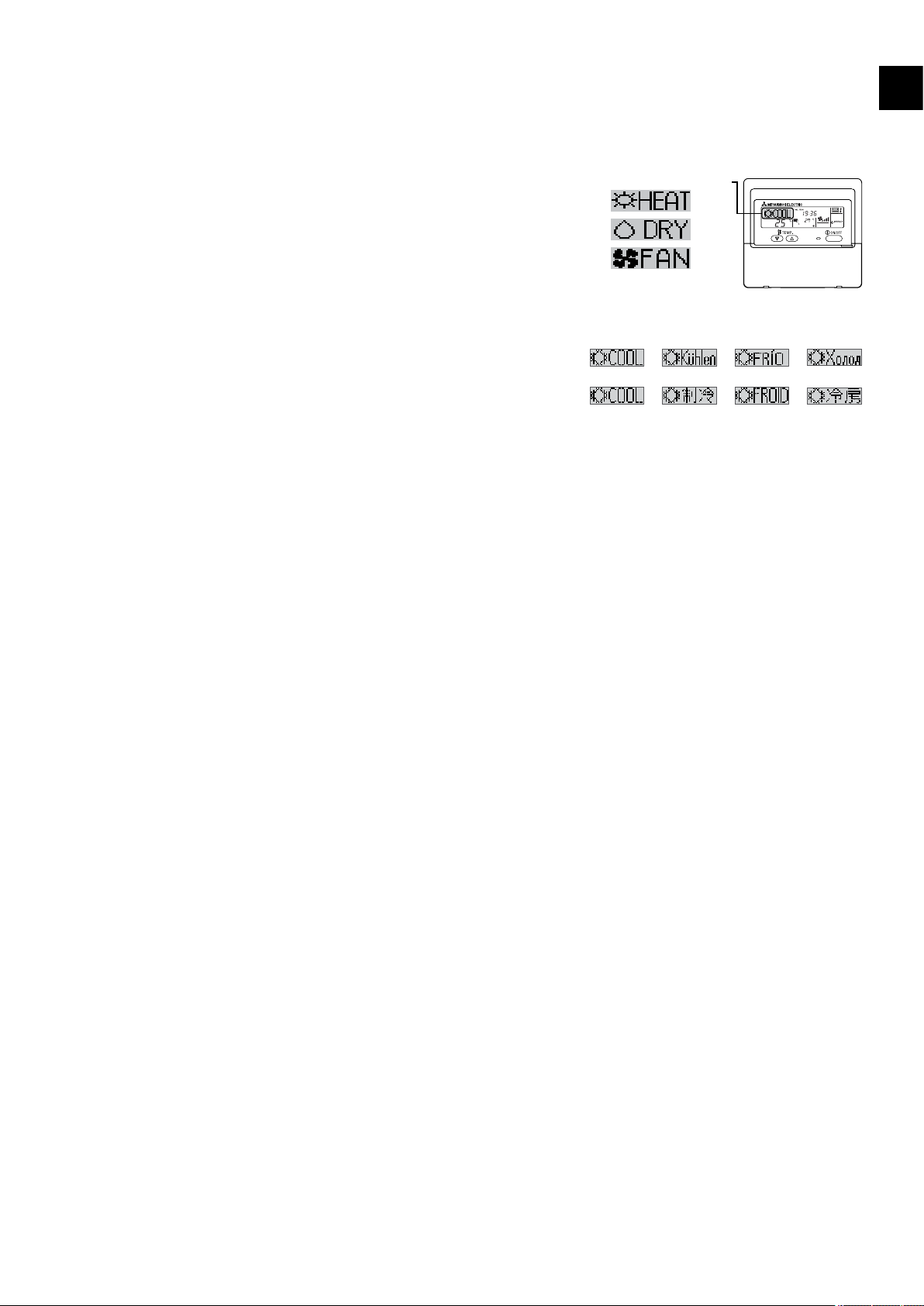
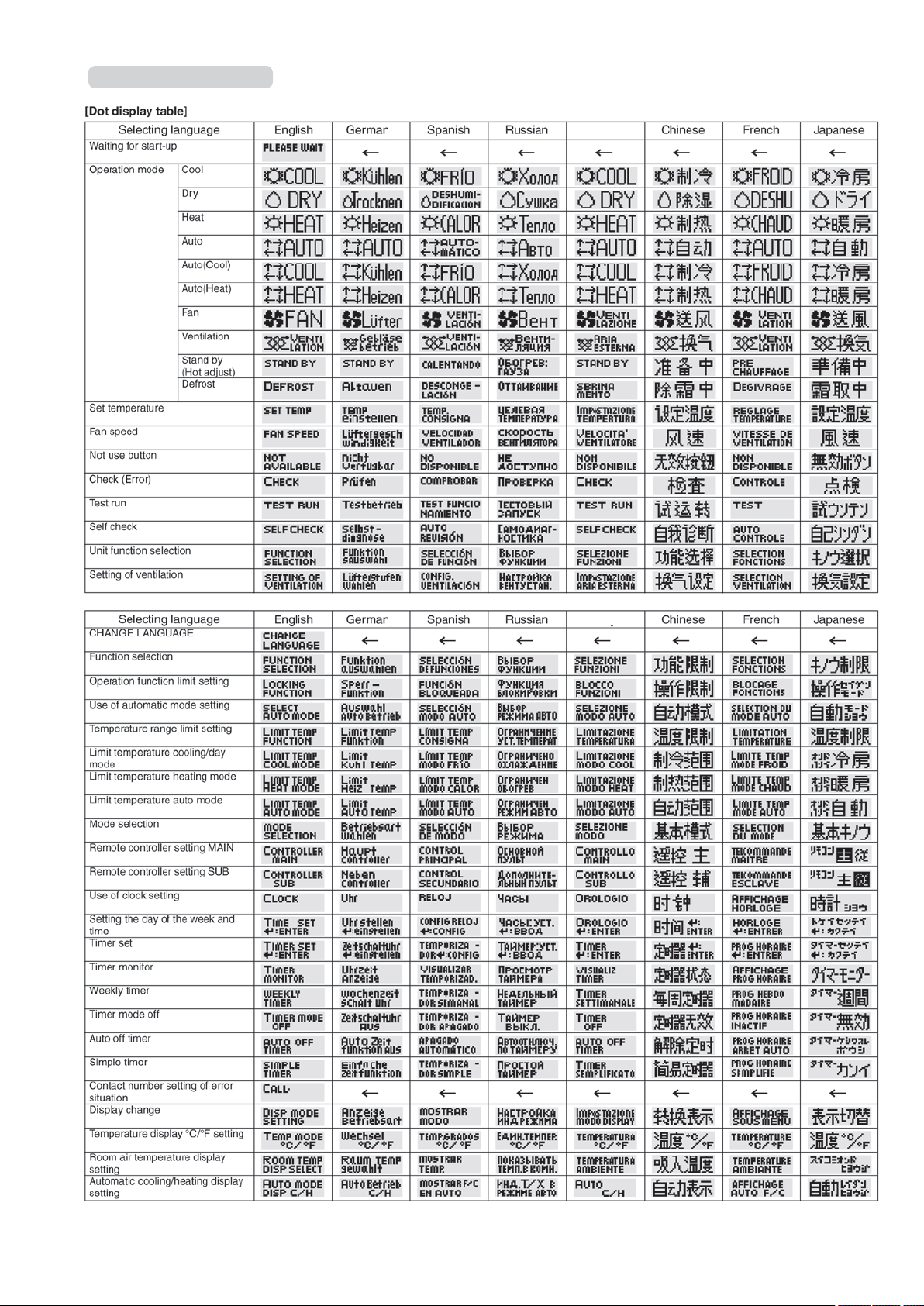
3. New Display
Dot liquid crystal display
LDisplay example [Operation mode]
[Japanese]
[Russian][English]
[Itarian]
[German]
[Chinese]
[Spanish]
[French]
Various information is displayed and conveyed clearly, enabling more accurate operation of the air conditioner.
3.1 Dot Liquid Crystal Display (LCD)
The dot liquid crystal display enables quick understanding of the operation
state.
Display example [Cool mode]
3.2 Multi-language Display
In addition to English, contents can be displayed in 7 other languages.
This function makes the remote controller very useful in facilities where foreigners a
re present.
4. The Other Functions
4.1 Temperature Range Limit Setting
Enables operation of air conditioner at comfortable temperatures at all times.
Upper and lower limits can be established for the temperature setting. This prevents overcooling or overheating, thereby contributing to
energy saving.
. Advantage of New MA Remote Controller
!
4.2 Auto Off Timer
Shuts off wasteful air conditioner operations.
Operation is stopped automatically when the preset time elapses following the start of operation, thereby preventing wasteful
operations.
The time can be set from 30 minutes to 4 hours in 30-minute increments.
4.3 Simple Operation Lock
Prevents others from changing settings without permission.
This lets you disable all the buttons or all the buttons except for the [ON/OFF] button, preventing mischief and incorrect operations.
3
. New Functions
@
Function Description
. New Functions
@
Easy maintenance
Operation data monitor function
function
Displays information necessary for maintenance.
Below information for easy maintenance of air-conditioner can be
displayed.
• Compressor •
• Number of ON/OFF times
• Operating current (A)
• Outdoor unit • Heat exchanger temperature (°C)
• Discharge temperature (°C)
• Outside air temperature (°C)
• Indoor unit • Intake air temperature (°C)
• Heat exchanger temperature (°C)
• Filter operating time (hours)
The operation state of inverter models can be monitored using the
maintenance stable-operation control (fixed frequency)
Information necessary for maintenance can be displayed on the
remote controller.
Accumulated operating time
Available when
connect
○
PU(H)
SUZ
MXZ
series
×
PUHZ
series
Go to
page
6
48
Error code monitor function
Contact number display
Multi language display
Temperature display (°C/°F) setting
Room temperature display setting
Auto heat/cool display setting
Weekly schedule timer
"Operation limit function setting
(Operation lock)"
Temperature range limit function
Clock function setting
Auto off timer
Simple timer
Error code is displayed in the service inspection monitor.
Displays the contact telephone number to be called when an error
occurs.
In addition to English, contents can be displayed in 7 other lan-
guages.
• English,
Italian, Chinese, French, Japanese
Enables you to set the unit (°C/°F) in which temperatures are to
be displayed.
Enables you to set whether to show or hide the indoor (room)
temperature.
Enables you to set whether to display or hide “COOL”/“HEAT” in
auto mode.
Provides a built-in weekly timer that allows you to make on/off and
temperature settings.
Up to 8 patterns can be set for each day of the week.
Lets you disable all the buttons or all the buttons except for the
[ON/OFF] button, preventing mischief and incorrect operations.
Enables you to establish upper and lower limits for the temperature setting. This prevents overcooling or overheating, thereby
contributing to energy saving.
Enables you to set whether to use the clock function.
Stops operation when the preset time elapses following the start
of operation.
The time can be set from 30 minutes to 4 hours in 30-minute in
crements.
By default,
To switch to the auto off timer, select it using the remote
controller’s function selection.
Enables you to set on/off settings in 1-hour increments within 72
hours.
German, Spanish, Russian,
the weekly timer is selected.
-
○ ○
○ ○
○ ○
○ ○
○ ○
○ ○
○ ○
○ ○
○ ○
○ ○
○ ○
○ ○
44
33
12
35
36
37
23
14
18
21
26
29
Remote controller main/sub setting
4
Enables you to set the remote controller as the main or sub.
○ ○
20
°F°C
°F°C
ERROR CODE
AFTER
TIMER
TIME SUN MON TUE WED THU FRI SAT
ON
OFF
Hr
AFTER
FILTER
FUNCTION
ONLY1Hr.
WEEKLY
SIMPLE
AUTO OFF
PAR-21MAA
ON/OFF
FILTER
CHECK
OPERATION
CLEAR
TEST
TEMP.
MENU
BACK DAY
MONITOR/SET
CLOCK
ON/OFF
. Appearance
#
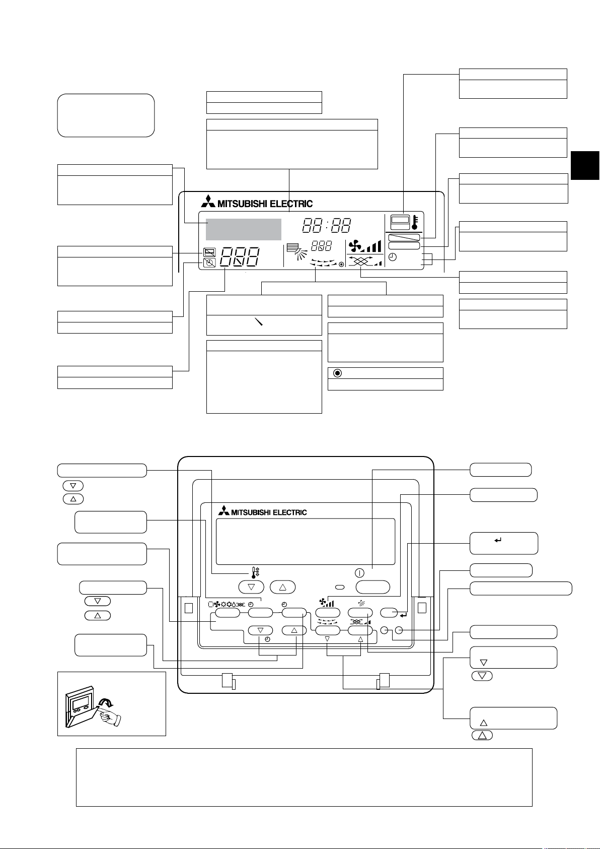
1. Display Section
For purposes of this explanation,
all parts of the display are shown
as lit. During actual operation, only
the relevant items will be lit.
Identies the current operation
Shows the operating mode, etc.
* Multilanguage display is sup-
ported.
“Centrally Controlled” indicator
Indicates that operation of the remote controller has been prohibited
by a master controller.
“Timer is Off” indicator
Indicates that the timer is off.
Temperature setting
Shows the target temperature.
Day-of-Week
Shows the current day of the week.
Time/Timer Display
Shows the current time, unless the simple or Auto Off
timer is set.
If the simple or Auto Off timer is set, shows the time re
maining.
Up/Down Air Direction indicator
The indicator shows the direction of the outcoming airflo .
“One Hour Only” indicator
Displayed if the airflow is set to
low and downward during COOL
or DRY mode. (Operation varies
according to model.)
The indicator goes off after 1 hour,
at which time the airflow direction
also changes.
Room Temperature display
Shows the room temperature.
Louver display
Indicates the action of the swing
louver. Does not appear if the lou-
stationary.
ver is
(Power On indicator)
Indicates that the power is on.
“Sensor” indication
Displayed when the remote controller sensor is used.
“Locked” indicator
Indicates that remote controller
-
buttons have been locked.
“Clean The Filter” indicator
Comes on w hen it i s ti me t o
clean the filte .
Timer indicators
The indicator comes on if the
corresponding timer is set.
. Appearance
#
Fan Speed indicator
Shows the selected fan speed.
Ventilation indicator
Appears when the unit is running
in Ventilation mode.
2. Operation Section
Set Temperature buttons
Down
Up
Timer Menu button
(Monitor/Set button)
Mode button (Return but-
ton)
Set Time buttons
Back
Ahead
Timer On/Off button
(Set Day button)
Opening the
door.
Note:
If you press a button for a feature that is not installed at the indoor unit, the remote controller will display the “Not Available”
message.
If you are using the remote controller to drive multiple indoor units, this message will appear only if the feature is not present
at every unit connected.
ON/OFF button
Fan Speed button
Filter button
(<Enter> button)
Test Run button
Check button (Clear button)
Airflow Up/Down butto
Louver button
(
Operation button)
To preceding operation
number.
Ventilation button
(
Operation button)
To next operation number.
5
●Reduces maintenance work drastically.
●Enables you to check operation data of the indoor and outdoor units by remote controller.
Furthermore, use of maintenance stable-operation control that fixes the operating frequency, allows smooth inspection, even for
inverter models.
1. Maintenance Mode Operating Method
* If you are going to use the " 2. Guide for Operation Condition ", set the airflow to "High" before activating maintenance mode.
●
Switching to maintenance mode
Maintenance mode can be activated either when the air conditioner is operated or stopped.
It cannot be activated during test run.
Maintenance information can be viewed even if the air conditioner is stopped.
■
Remote controller button information
Operation mode
(1) Press the
TEST
button for 3 seconds to switch to maintenance mode.
[Display ]
MAINTENANCE
If stable operation is unnecessary or if you want to check the data with the air conditioner stopped, skip to step (4).
●
Fixed Hz operation
The operating frequency can be fixed to stabilize operation of inverter model.
If the air conditioner is currently stopped, start it by this operation.
(2) Press the
MODE
button to select the desired operation mode.
[Display ]
(3) Press the
FILTER
( ) button to confirm the setting.
[Display ] Waiting for stabilization
HEAT
STABLE MODE
STABLE MODE
CANCEL
COOL
STABLE MODE
Stable cooling
operation
Stable heating
operation
Stable operation
cancellation
Stabilized
Discharge temperature 64°C
Remove the
service panel.
Measure
the intake air
temperature.
Measure the discharge
temperature.
Measure the outside air
temperature
?
lIndoor unit l
lOutdoor unit l
Smooth Maintenance Function
●Conventional inspection work
Easy maintenance information (unit)
Compressor Outdoor unit Indoor unit
Accumulated operating
Heat exchanger Room
time
(×10 hours) temperature (°C) temperature (°C)
Number of ON/OFF Discharge Heat exchanger
times (×10 times) temperature (°C) temperature (°C)
Operating Outside air Filter operating
current (A) temperature (°C) time* (Hours)
* The filter operating time is the time that has elapsed since the filter was reset.
Active / cancel
maintenance mode
Confirm
Outdoor unit information
Compressor
information
Indoor unit information
. Easy Maintenance Function (For Mr.SLIM PUHZ series)
$
6
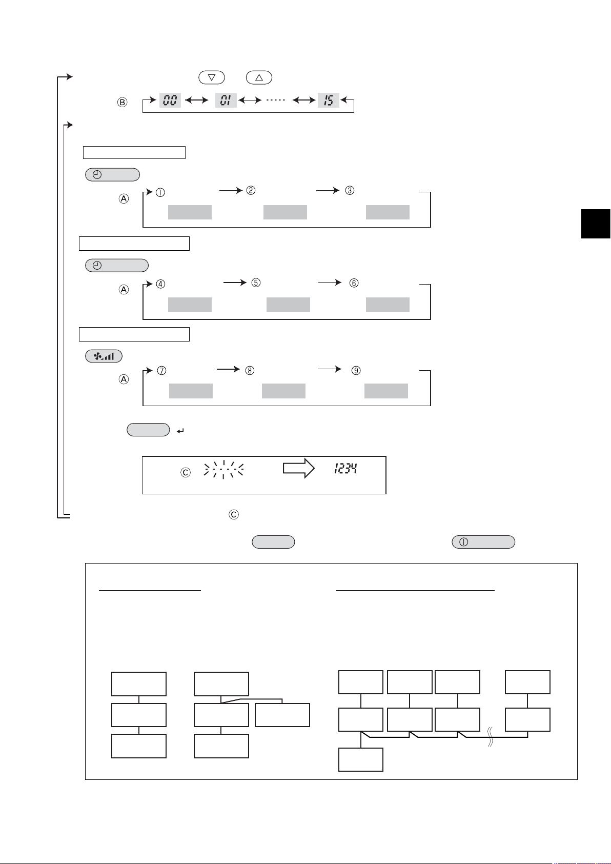
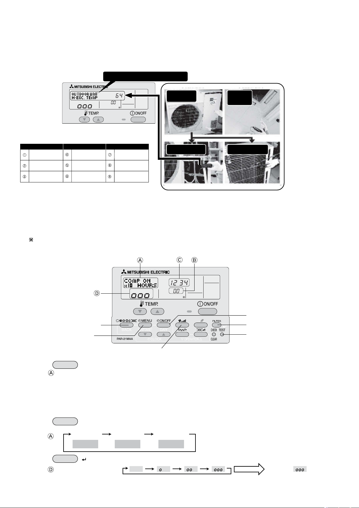
Data measurement
When the operation is stabilized, measure operation data as explained below.
(4) Press the [TEMP] buttons (
and ) to select the desired refrigerant address.
[Screen ]
(5) Select the type of data to be displayed.
After selecting, go to step (6).
Compressor information
MENU
button
[Display ]
Outdoor unit information
ON/OFF
button
[Display ]
Indoor unit information
button
[Display ]
(6) Press the
FILTER
( ) button to confirm the setting.
[Display example for accumulated operating time]
(7) Data is displayed on the display (at ).
To check the data for each item, repeat steps (5) to (7).
(8) To cancel maintenance mode, press the
TEST
button for three seconds or press the
ON/OFF
button.
COMP ON
x10 HOURS
COMP ON
x100 TIMES
COMP ON
CURRENT (A)
Cumulative
operation time
ON/OFF Number Operating current
OUTDOOR UNIT
H.EXC. TEMP
OUTDOOR UNIT
OUTLET TEMP
OUTDOOR UNIT
OUTDOOR TEMP
Heat exchanger
temperature
Comp discharge
temperature
Outdoor ambient
temperature
INDOOR UNIT
INLET TEMP
INDOOR UNIT
H.EXC. TEMP
INDOOR UNIT
FILTER USE H
Indoor room
temperature
Heat exchanger
temperature
Filter operating
time
12,340 hours
Display
Waiting for response
Blinking
After approx.
10 seconds
[1:1]
Refrigerant
address=00
[Twin]
Refrigerant
address=00
Outdoor
unit
Indoor unit
02
Indoor unit
01
Outdoor
unit
Remote
controller
Remote
controller
Indoor unit
01
Refrigerant address
Single refrigerant system
In the caseof single refrigerantsystem, the refrigerantaddress
is "00" and no operation is required.
Simultaneous twin, triple andquad unitsbelongto this category
(single refrigerant system).
Multi refrigerant system (group control)
Up to 16 refrigerant systems (16 outdoor units) can be connected asa groupby oneremote controller.To checkor setthe
refrigerant addresses.
Refrigerant
address
00
Refrigerant
address
01
Refrigerant
address
02
Refrigerant
address
15
Outdoor
unit
Indoor unit
01
Outdoor
unit
Indoor unit
01
Outdoor
unit
Indoor unit
01
Outdoor
unit
Indoor unit
01
Remote
controller
Easy Maintenance Function (For Mr. SLIM PUHZ series)
.
$
7
2. Guide for Operation Condition
Inspection item Result
Power supply
Loose con-
nection
Breaker Good Retightened
Terminal block Outdoor Unit Good Retightened
Indoor Unit Good Retightened
(Insulation resistance) M
(Voltage) V
Accumulated operating time Time
Number of ON/OFF times Times
Current A
Refrigerant/heat exchanger temperature
COOL °C HEAT °C
Refrigerant/discharge temperature
COOL °C HEAT °C
Air/outside air temperature COOL °C HEAT °C
(Air/discharge temperature) COOL °C HEAT °C
Appearance Good
Cleaning required
Heat exchanger Good
Cleaning required
Sound/vibration None Present
Air/Room air temperature COOL °C HEAT °C
(Air/discharge temperature) COOL °C HEAT °C
Refrigerant/heat exchanger temperature
COOL °C HEAT °C
Filter operating time* Time
Decorative panel Good
Cleaning required
Filter Good
Cleaning required
Fan Good
Cleaning required
Heat exchanger Good
Cleaning required
Sound/vibration None Present
Compressor
Temperature
Cl ea nli-
ness
Outdoor Unit
Temperature
Cleanliness
Indoor Unit
* The filter operating time is the time that has elapsed since the filter was reset.
Check Points
Enter the temperature differences between , , and into
the graph given below.
Operation state is determined according to the plotted areas on
the graph.
For datameasurements, set the fan speed to "Hi" before activating maintenance mode.
Is "000" displayed stably in Display
on the remote controller?
Is "000" displayed stably in Display
D
on the remote controller?
( Discharge temperature) - ( Outdoor
heat exchanger temperature)
( Indoor room temperature) - (
Indoor heat exchanger temperature)
( Discharge temperature) - ( Indoor
heat exchanger temperature)
( Indoor heat exchanger temperature) ( Indoor room temperature)
Cool
Classification Item Result
Inspection
Temperature
difference
Heat
Inspection
Temperature
difference
Stable Unstable
°C
°C
Stable Unstable
°C
°C
* Fixed Hz operation may not be possible under the following tempera-
ture ranges.
A)In cool mode, outdoor intake air temperature is 40 °C or higher or
indoor room temperature is 23 °C or lower
B)In heat mode, outdoor intake air temperature is 20
°C or higher or
indoor room temperature is 25
°C or lower
* If the air conditioner is operated at a temperature range other than the
ones above but operationisnot stabilized after30 minutesor more have
elapsed, carry out inspection.
* In heat mode, the operation state may vary due to frost forming on the
outdoor heat exchanger.
°C
45
40
35
30
25
20
15
10
5
0
10 20 30 40 50 60 70 80
Normal
Filter inspection
Inspection C
Inspection A
Inspection B
°C
45
40
35
30
25
20
15
10
5
°C°C
Normal
Filter inspection
Inspection C
Inspection A
Inspection B
Cool mode Heat mode
( Indoor room temperature) - ( Indoor
heat exchanger temperature)
( Indoor heat exchanger temperature) -
( Indoor room temperature)
[ Discharge temperature] -- [ Outdoor
heat exchanger temperature]
[ Discharge temperature] - [ Indoor
heat exchanger temperature]
Result
Normal operation state
Filter may be clogged. *1
Performance has dropped. Detailed in-
spection is necessary.
Refrigerant amount is dropping.
Filter or indoor heat exchanger may be
clogged.
Area Check item
Judgment
Cool Heat
Normal
Filter inspection
Inspection A
Inspection B
Inspection C
* The above judgement is just guide based on Japanese standard
conditions.
It may bechanged depending onthe indoor andoutdoor temperature.
10 20 30 40 50 60 70 80
*1 If may be judged as "Filter inspection" due to the outdoor and indoor
temperature, even though it is not clogged.
8
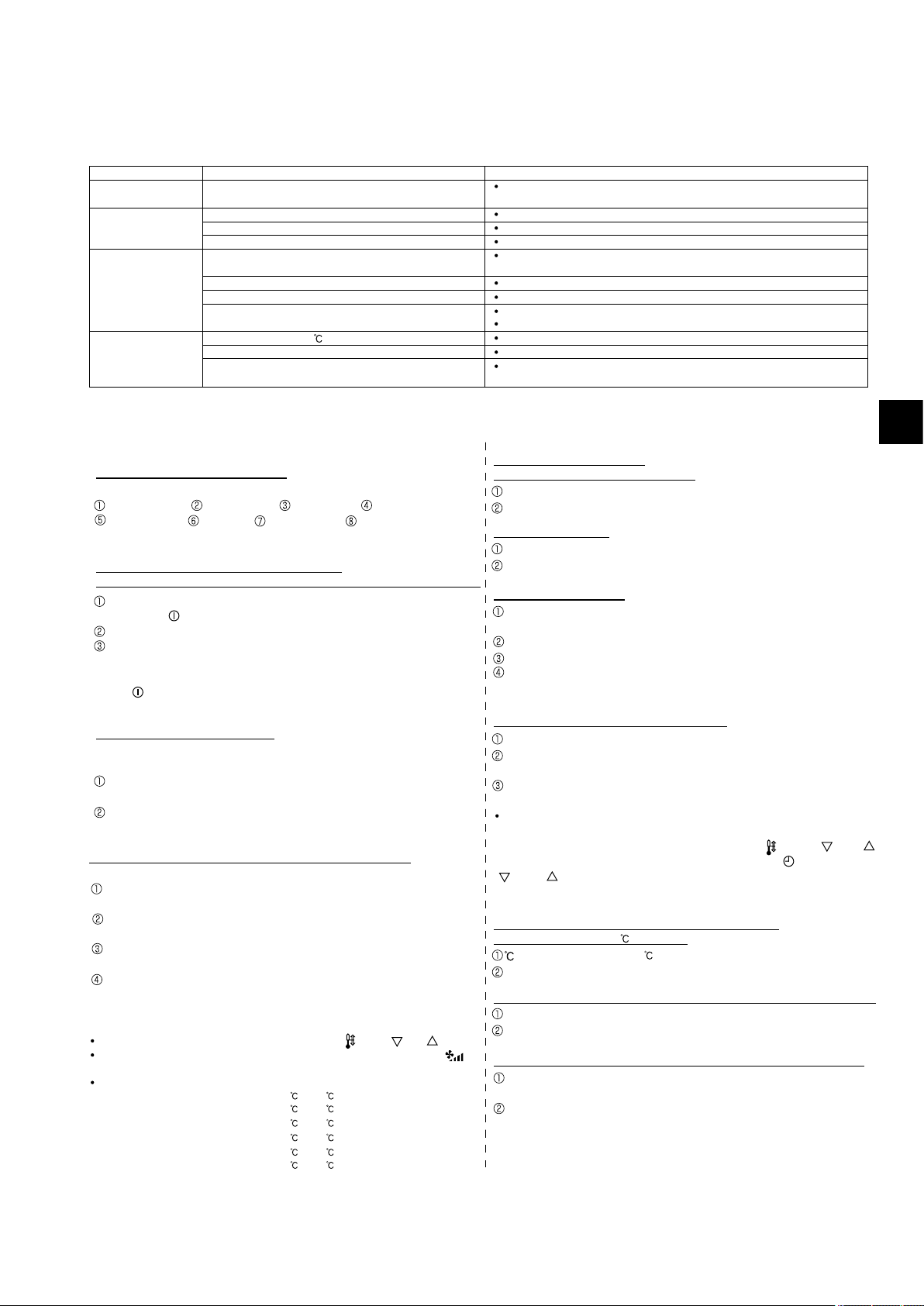
The setting of the following remote controller functions can be changed using the remote controller function selection mode.
Change the setting when needed.
Item 1
1.Change Language
("CHANGE LANGUAGE")
2.Function limit
("FUNCTION SELECTION")
3.Mode selection
("MODE SELECTION")
4.Display change
("DISP MODE SETTING")
Item 3 (Setting content)
Display in multiple languages is possible.
Setting the range of operation limit (operation lock)
Setting the use or non-use of "automatic" operation mode
Setting the temperature adjustable range (maximum, minimum)
Selecting main or sub remote controller
*
When 2 remote controllers are connected to 1 group, 1 controller must be set to sub.
Setting the use or non-use of clock function
Setting the timer type
Contact number display in case of error
Setting the telephone number
Setting the temperature unit ( °C or °F) to display
Setting the use or non-use of the display of indoor (suction) air temperature
Setting the use or non-use of the display of "Cooling" or "Heating" display during
operation with automatic mode
Item 2
Language setting to display
(1)
Operation function limit setting (operation lock) ("
LOCKING FUNCTION
")
(2)
Use of automatic mode setting ("SELECT AUTO MODE")
(3)
Temperature range limit setting ("LIMIT TEMP FUNCTION")
(1)
Remote controller main/sub setting ("CONTROLLER MAIN/SUB")
(2) Use of clock setting ("CLOCK")
(3) Timer function setting ("WEEKLY TIMER")
(4) Contact number setting for error situation ("CALL.")
(1) Temperature display /°F setting ("TEMP MODE °C /°F")
(2)
Room temperature display setting ("ROOM TEMP DISP SELECT")
(3)
Automatic cooling/heating display setting ("AUTO MODE DISP C/H")
[Function selection flowchart] Refer to next page.
[1]
Stop the air conditioner to start remote controller function selection mode.→
[2] Select from item1.→ [3] Select from item2.→ [4] Make the setting.
(Details are specified in item3)
→
[5] Setting completed. → [6] Change the display to the normal one. (End)
[Detailed setting]
[4] -1. CHANGE LANGUAGE setting
The language that appears on the dot display can be selected.
Japanese (JP), English (GB), German (D), Spanish (E),
Russian (RU), Italian (I), Chinese (CH), French (F)
[4] -2. Function limit (FUNCTION SELECTION)
(1) Operation function limit setting
(operation lock)(LOCKING FUNCTION)
no1 : Operation lock setting is made on all buttons other than
the [
ON/OFF] button.
no2 : Operation lock setting is made on all buttons .
OFF (Initial setting value) : Operation lock setting is not made
* To make the operation lock setting valid on the normal screen, it is
necessary to press buttons (Press and hold down the [FILTER]
and [ ON/OFF] buttons at the same time for 2 seconds.) on
the normal screen after the above setting is made..
(2) Use of automatic mode setting
When the remote controller is connected to the unit that has automatic operation mode, the following settings can be made.
ON (Initial setting value) : The automatic mode is displayed when
the operation mode is selected.
OFF : The automatic mode is not displayed
when the operation mode is selected.
[4] -3. Mode selection setting (MODE SELECTION)
(1) Remote controller main/sub setting
Main : The controller will be the main controller.
Sub : The controller will be the sub controller.
(2) CLOCK setting
ON : The clock function can be used.
OFF: The clock function cannot be used.
(3) Timer function setting
WEEKLY TIMER (initial setting):
The weekly timer can be used.
AUTO OFF TIMER: The auto off timer can be used.
SIMPLE TIMER : The simple timer can be used.
TIMER MODE OFF: The timer mode cannot be used.
* When CLOCK setting is OFF, the "WEEKLY TIMER" cannot be used.
(4) Contact number setting for error situation
CALL OFF:
The set contact numbers are not displayed in case of error.
CALL **** *** **** : The set contact numbers are displayed in case
of error.
(3) Temperature range limit setting (LIMIT TEMP FUNCTION)
After this setting is made, the temperature can be changed within the set range.
LIMIT TEMP COOL MODE :
The temperature range can be changed on cooling/dry mode.
LIMIT TEMP HEAT MODE :
The temperature range can be changed on heating mode.
LIMIT TEMP AUTO MODE :
The temperature range can be changed on automatic mode.
OFF (initial setting) : The temperature range limit is not active.
*
When the setting, other than OFF, is made, the temperature range limit setting
on cooling, heating and automatic mode is made at the same time. However
the range cannot be limited when the set temperature range has not changed.
To increase or decrease the temperature, press the [ TEMP ( ) or ( )] button.
To switch the upper limit setting and the lower limit setting, press the
[ ]
button. The selected setting will blink and the temperature can be set.
Settable range
Cooling/Dry mode : Lower limit: 19 ~ 30 , 67°F~87°F
Upper limit: 30 ~ 19 , 87°F~67°F
Heating mode : Lower limit: 17 ~ 28 , 63°F~83°F
Upper limit: 28 ~ 17 , 83°F~63°F
Automatic mode : Lower limit: 19 ~ 28 , 67°F~83°F
Upper limit: 28 ~ 19 , 83°F~67°F
CALL_ : The contact number can be set when the display is as
shown on the left.
Setting the contact numbers
To set the contact numbers, follow the follo
wing procedures
.
Move the blinking cursor to set numbers. Press the [
TEMP. ( )
and(
)]
button to move the cursor to the right (left). Press the [
CLOCK
(
) and ( )] button to set the numbers.
[4] -4. Display change setting (DISP MODE SETTING)
(1) Temperature display / °F setting
: The temperature unit is used.
°F : The temperature unit °F is used.
(2) Room temperature display setting (ROOM TEMP DISP SELECTION)
ON : The room temperature is displayed.
OFF: The room temperature is not displayed.
(3) Automatic cooling/heating display setting (AUTO MODE DISP C/H)
ON : One of "Automatic cooling" and "Automatic heating" is displayed
under the automatic mode is running.
OFF: Only "Automatic" is displayed under the automatic mode.
. How to Select Functions of remote controller
%
Function Items
1.
How to Select Functions of remote controller
.
%
9
OFF
no1
no2
OFF
ON
OFF
ON
OFF
OFF
CALL-
ON
OFF
ON
OFF
C
F
English
German
Spanish
Russian
Italian
Chinese
French
Japanese
Item 3
Item 2Item 1
Hold down the button and press the button for 2 seconds.
Remote controller function selection mode
Normal display
(Display when the air conditioner is not running)
Room air temperature is not displayed.
One of “Automatic cooling” and “Automatic heating” is displayed
under the automatic mode is running. (Initial setting value)
Only “Automatic” is displayed under the automatic mode.
Change
Language
Function
selection
Mode
selection
Display
mode setting
Operation lock setting is not used.
(Initial setting value)
Operation lock setting is except On/Off button.
Operation lock setting is all buttons.
The automatic mode is displayed when the operation
mode is selected. (Initial setting value)
The automatic mode is not displayed when the operation mode
is selected.
The temperature range limit is not active. (Initial setting value)
The temperature range can be changed on cooling/dry mode.
The temperature range can be changed on heating mode.
The temperature range can be changed on automatic mode.
The remote controller will be the main controller. (Initial setting value)
The remote controller will be the sub controller.
The clock function can be used. (Initial setting value)
The clock function cannot be used.
Weekly timer can be used. (Initial setting value)
Auto off timer can be used.
Simple timer can be used.
Timer mode cannot be used.
The set contact numbers are not displayed in case of error.
(Initial setting value)
The set contact numbers are displayed in case of error.
The temperature unit °C is used. (Initial setting value)
The temperature unit °F is used.
Room air temperature is displayed. (Initial setting value)
Fixed air flow direction mode
Not necessary to set this mode. Refer to OPERATION MANUAL of
indoor unit for details on operation.
Automatic filter elevation panel up/down operation mode
Not necessary to set this mode. Refer to OPERATION MANUAL of
Optional Parts (Panel) for details on operation.
One of the
description
marked*
on the right
will be
displayed.
(current setting)
*
*
*
*
PAR-21MAA
ON/OFF
FILTER
CHECK
OPERATION
CLEAR
TEST
TEMP.
MENU
BACK DAY
MONITOR/SET
CLOCK
ON/OFF
Hold down the button and press the button for 2 seconds.
Press the operation mode button.
Press the TIMER MENU button.
Press the TIMER ON/OFF button.
Dot display
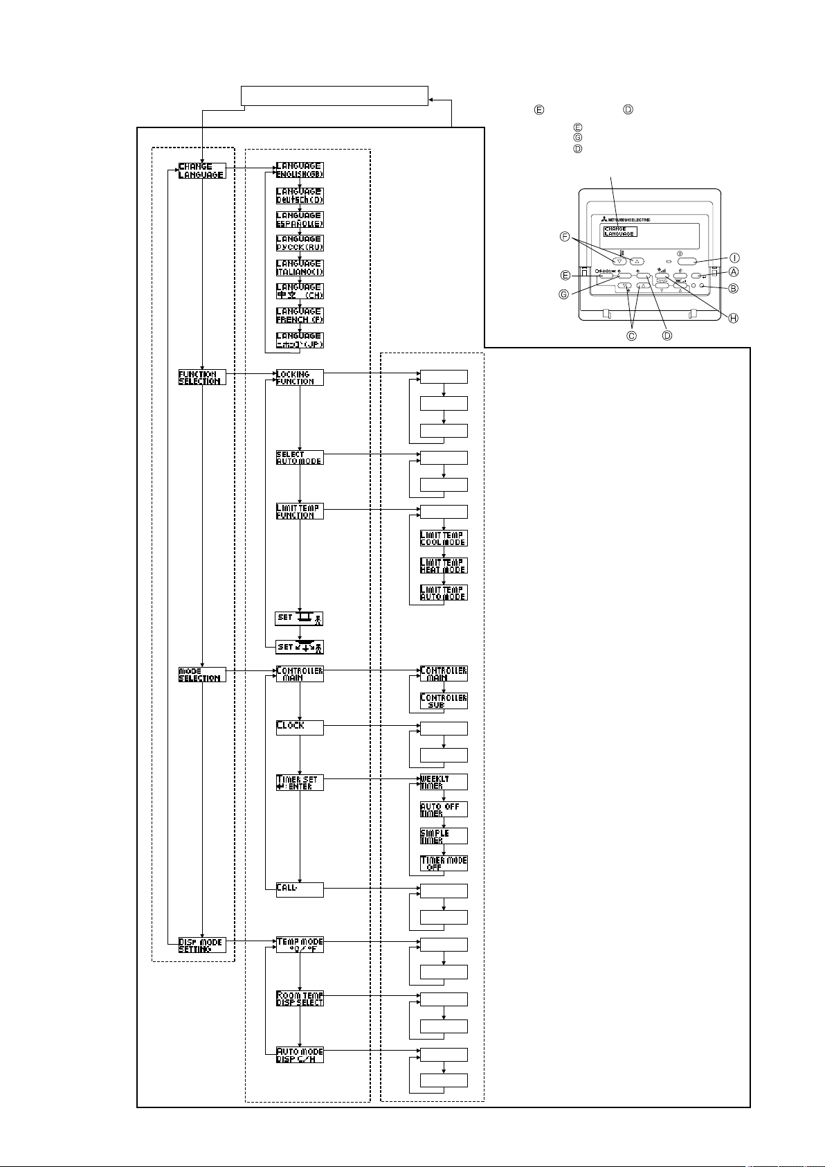
2. Flowchart of Function Setting
Setting language (English)
10
(ON)(OFF)
Function Selection of Remote Controller
Standard Control Screens
Set Day Time
Timer Monitor Timer Setup
°С
°С
°C
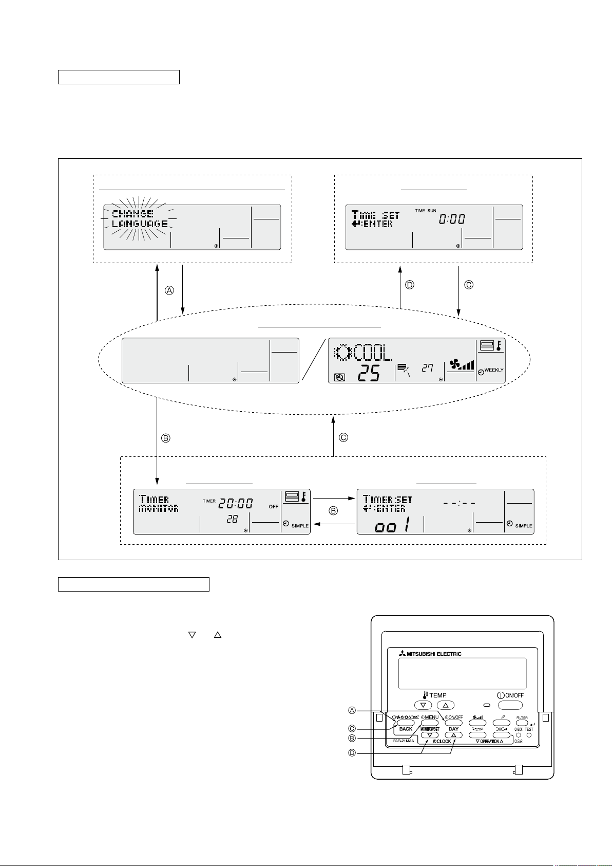
3. Screen Structure for Function Setting
Description of each screen
• Function selection of remote controller : Used to set the timer function and operation limit function, etc.
• Set day time : Used to set the current day of the week and time.
• Standard control screen : Used to set the air conditioner’s operating state.
• Timer monitor screen : Used to display the current settings of the timers (weekly, simple, auto off).
• Timer set up screen : Used to set the timers (weekly, simple, auto off).
How to change the screen display
: Press the [ON/OFF] button for two seconds while holding down the [MODE] button.
A
: Press the [MENU] button.
B
: Press the [MODE] (BACK) button.
C
: Press the [CLOCK] buttons (
D
and ).
11

English
Italian
German
Chinese
Spanish
French
Russian
Japanese
4. Function Setting Mode
(4)
(2)
(3)
(1)
CHANGE
LANGUAGE
FUNCTION
SELECTION
MODE
SELECTION
DISP MODE
SETTING
[English]
LANGUAGE
ENGLISH(GB)
[Japanese]
LANGUAGE
(JP)
[French]
LANGUAGE
FRENCH(F)
[Chinese]
LANGUAGE
(CH)
[Italian]
LANGUAGE
ITALIANO(I)
[Russian]
LANGUAGE
pycck(RU)
[Spanish]
LANGUAGE
ESPAÑOL(E)
[German]
LANGUAGE
Deutsch(D)
4.1 Change Language
The language that appears on the dot display can be selected.
The following languages can be selected.
English (GB)
1
Italian (I)
5
German
2
Chinese
6
(D)
(CH)
Changing the Display Language
Spanish (E)
3
French (F)
7
Display example
4
8
Russian (RU)
Japanese (JP)
(1) While pressing the
selection mode.
(2) Press the
[Display
(3) Press the
[Display
MODE
]
MENU
]
(4) While pressing the
complete.
Display
example
(Cool mode)
MODE
button, press the
ON/OFF
button for 2 seconds to activate the remote controller’s function
button until appears on the screen (at ).
button to select the desired display language.
MODE
button, press the
ON/OFF
button for two seconds to return to normal mode. Setting is now
12
Multi Language Display
Italian
Italian
13
(1)(5)
(2)
(3)
(4)
(6)(7)
4.2 Function Setting
CHANGE
LANGUAGE
FUNCTION
SELECTION
MODE
SELECTION
DISP MODE
SETTING
LOCKING
FUNCTION
SELECT
AUTO MODE
LIMIT TEMP
FUNCTION
*
Lock All Except
ON/OFF
No limitation Lock All Buttons
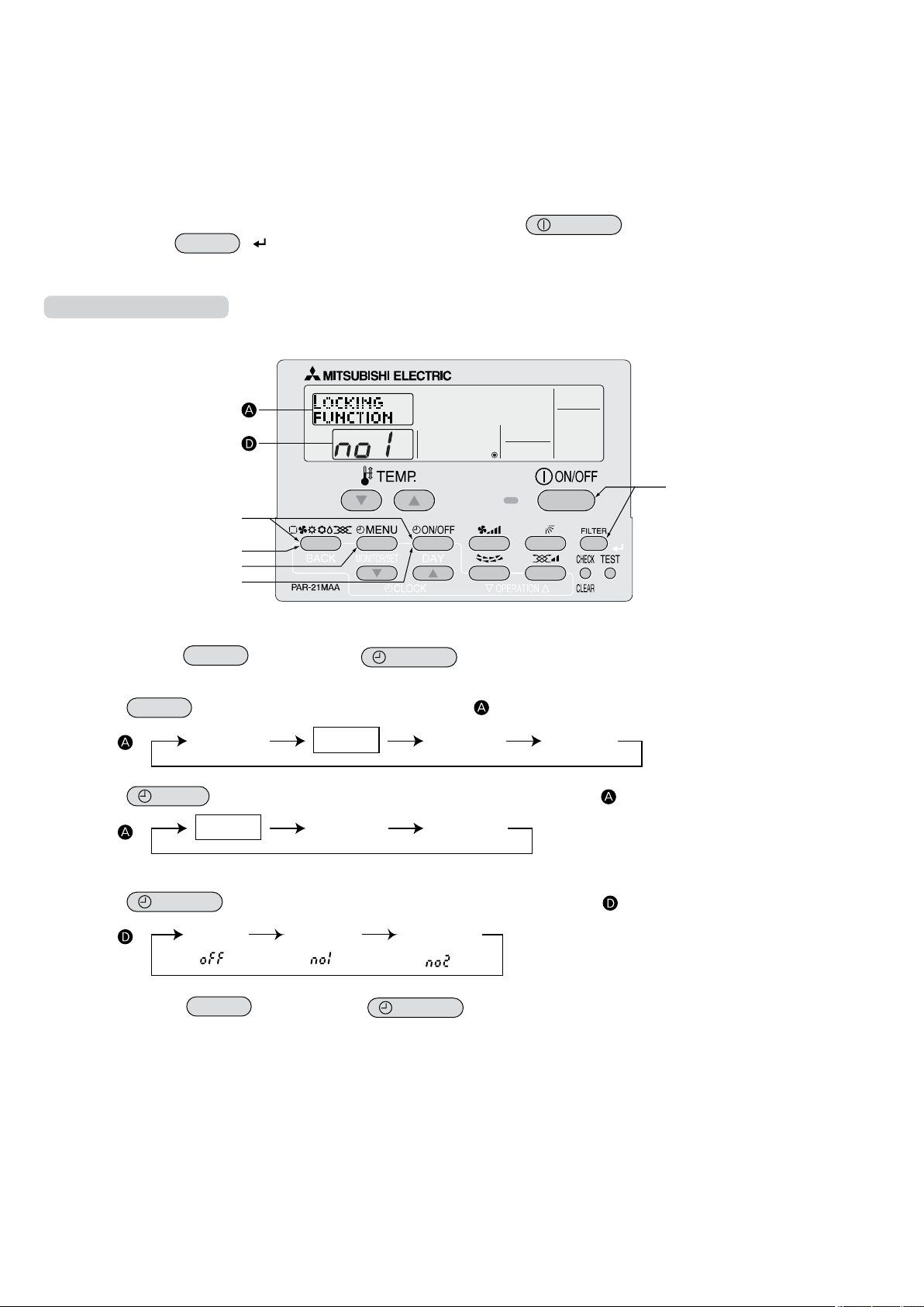
4.2.1 Operation Lock (Operation Function Limit Setting)
The following settings can be made.
no1 :All buttons except for the [ON/OFF] button are locked.
1
no2 :All
2
OFF (default) :No
3
buttons are locked.
buttons are locked.
* To activate this operation lock function on the normal screen, hold down the
holding down the
FILTER
( ) button.
How to Lock the Buttons
Display example
(1) While pressing the
tion selection mode.
(2) Press the
MODE
MODE
button, press the
button to select
FUNCTION
SELECTION
ON/OFF
button for 2 seconds to activate the remote controller’s func-
on the screen (at ).
ON/OFF
button for 2 seconds while
[Display
(3) Press the
[Display
]
]
MENU
button until “LOCKING FUNCTION” appears on the screen (at ).
* Displays the mode that is set in “Temperature Range Limit Setting”.
(4) Press the
[Display
ON/OFF
]
(5) While pressing the
button until the desired lock mode appears on the screen (at ).
MODE
button, press the
ON/OFF
now complete.
Completing steps (1) to (5) allows use of the operation lock function.
To enable the lock function, carry out the following steps.
button for 2 seconds to return to normal mode. Setting is
14
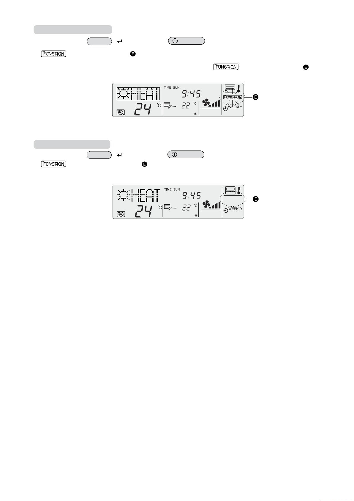
Enabling the Lock Function
(6) While pressing
tion.
* If a locked button is pressed while the operation lock function is in use,
the
FILTER
appears on the screen (at ).
( ) button
Display example when operation lock function is in use
, press the
ON/OFF
How to Unlock the Buttons
(7) While pressing
disappears from the screen (at ).
the
FILTER
( ) button
Display example when the operation lock function is not in use
, press the
ON/OFF
button for 2 seconds to enable the operation lock func-
will blink on the screen (at ).
button for 2 seconds.
15
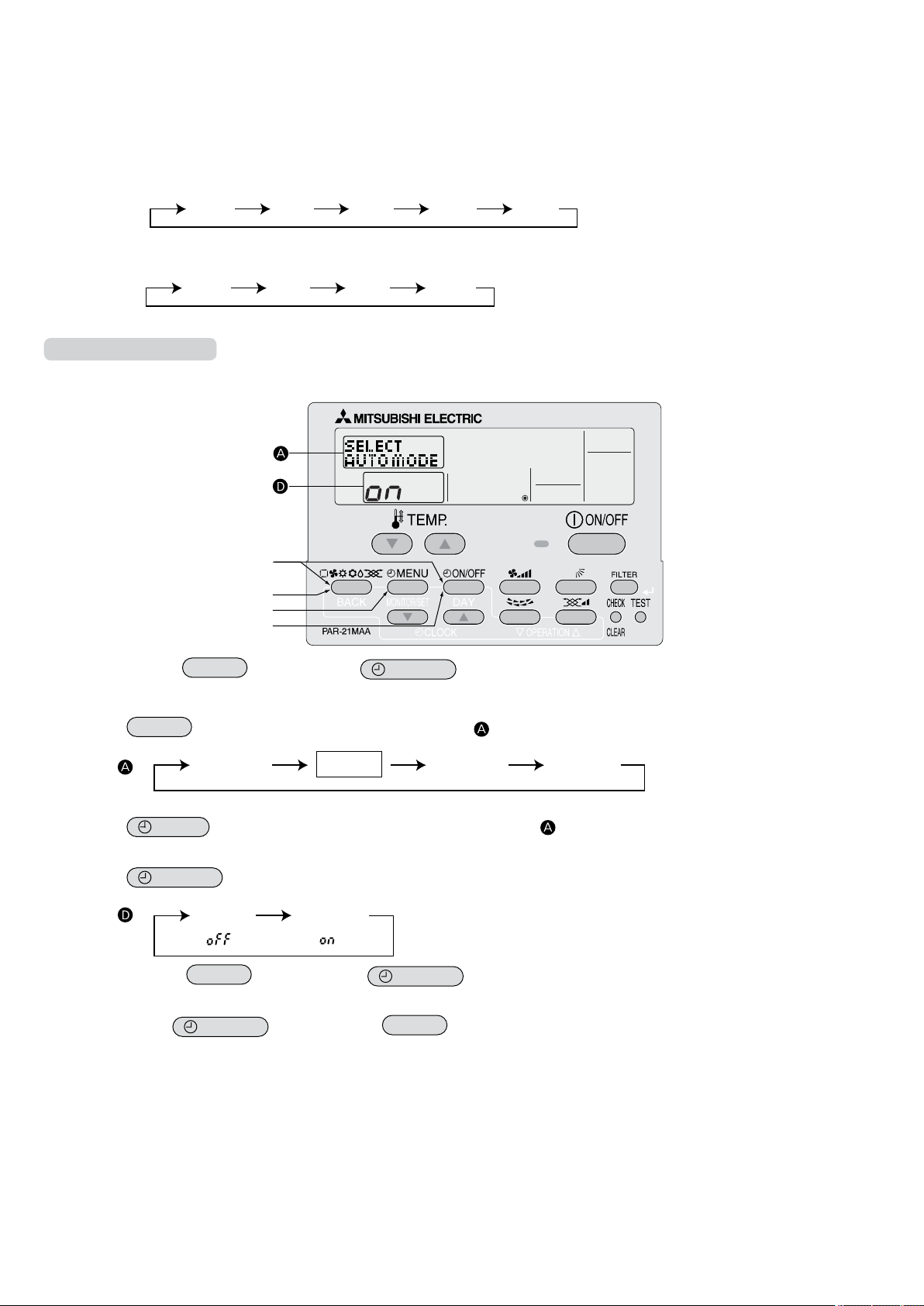
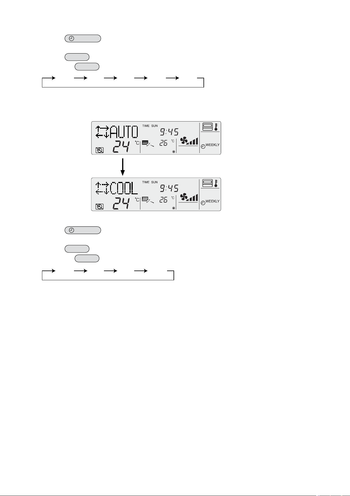
4.2.2 Auto Mode Setting
COOL DRY FAN HEATAUTO
COOL DRY FAN HEAT
(5)(1)
(2)
(3)
(4)
CHANGE
LANGUAGE
FUNCTION
SELECTION
MODE
SELECTION
DISP MODE
SETTING
SELECT
AUTO MODE
SELECT
AUTO MODE
The following settings can be made.
ON (default)
1
However,
Operation mode can be switched :
OFF : Even if the unit supports the auto mode, auto mode is not displayed when selecting an operation mode.
2
Operation mode can be switched :
How to Set Auto Mode
: Auto mode is displayed when selecting an operation mode only if the unit to be connected supports the auto
mode.
this does not apply if the unit to be connected does not support the auto mode.
Display example
(1) While pressing the
MODE
tion selection mode.
(2) Press the
[Display
(3) Press the
MODE
]
button to select
MENU
button so that
* The current setting is displayed.
(4) Press the
[Display
(5) While pressing the
ON/OFF
]
MODE
now complete.
* If you press the
ON/OFF
button, press the
FUNCTION
SELECTION
SELECT
AUTO MODE
ON/OFF
on the screen (at ).
appears on the screen (at ).
button for 2 seconds to activate the remote controller’s func-
button to select whether auto mode is to be used (on) or not (off).
button, press the
button before the
ON/OFF
MODE
button for 2 seconds to return to normal mode. Setting is
button, the settings you have made will be cancelled.
16
Screen display
COOL DRY FAN HEAT
*1
COOL DRY FAN HEAT
*1
AUTO
*1
when auto mode is set to ON
(1) Press the
The ON lamp lights up and operating contents are displayed on the LCD.
(2) Press the
Each time the
*1: If the remote controller is connected with the unit for cool operation only, “AUTO” and “HEAT” will not be displayed, nor
will it be possible to select them.
ON/OFF
MODE
MODE
button.
button.
button is pressed, the operation mode switches from one to another. “AUTO” is also displayed.
Display example when auto mode is set to ON
If AUTO MODE DISP C/H is ON (see 4.4.3), it takes about 10 seconds before the
display is switched from one mode to another.
Screen display
(1) Press the
The ON lamp lights up and operating contents are displayed on the LCD.
(2) Press the
Each time the
*1: If the remote controller is connected with the unit for cool operation only, “HEAT” will not be displayed.
when auto mode is set to OFF
ON/OFF
MODE
MODE
button.
button.
button is pressed, the operation mode switches from one to another, but “AUTO” is not displayed.
17
(6)
(7)(1)
(2)
(3)
(4)
(5)
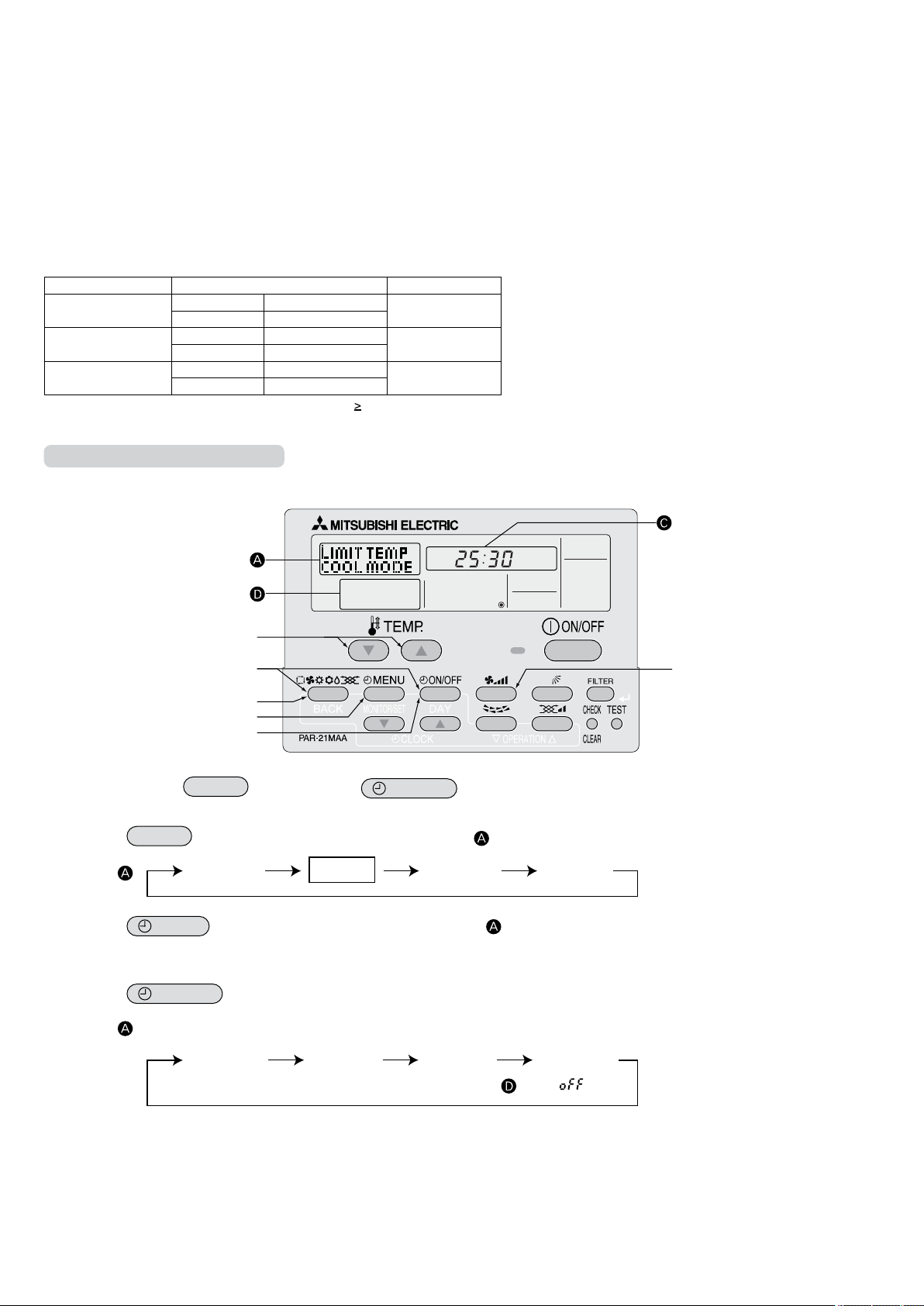
4.2.3 Temperature Range Limit Setting
CHANGE
LANGUAGE
FUNCTION
SELECTION
MODE
SELECTION
DISP MODE
SETTING
Display
DRY mode
COOL mode
HEAT mode AUTO mode* No limitation
LIMIT TEMP
AUTO MODE
LIMIT TEMP
FUNCTION
LIMIT TEMP
HEAT MODE
LIMIT TEMP
COOL MODE
The temperature setting range can be limited.
It can be limited for each mode.
Cool mode
1
Heat mode
2
Auto mode
3
OFF (default)
4
* When a mode other than OFF mode is set, temperature setting range limit setting for cool, heat and auto modes will be made
simultaneously.
However, limit setting will not be made unless the range has been changed.
COOL·DRY Mode Lower limit 19 °C – 30 °C
HEAT Mode Lower limit 17 °C – 28 °C
AUTO Mode Lower limit 19 °C – 28 °C
* Temperatures can be set within the range of “upper limit ” “lower limit”.
Limiting the Temperature Range
: The temperature setting range for cool/dry mode can be changed.
: The temperature setting range for heat mode can be changed.
: The temperature setting range for auto mode can be changed.
: The temperature setting range is not limited.
Setting range Standard setting
Upper limit 30 °C – 19 °C
Upper limit 28 °C – 17 °C
Upper limit 28 °C – 19 °C
Display example
19 °C – 30 °C
17 °C – 28 °C
19 °C – 28 °C
(1) While pressing the
MODE
button, press the
ON/OFF
button for 2 seconds to activate the remote controller’s func-
tion selection mode.
(2) Press
the
[Display
(3) Press the
MODE
]
MENU
button to select
button to select
FUNCTION
SELECTION
LIMIT TEMP
FUNCTION
on the screen (at ).
on the screen (at ).
* If a setting change was made previously, the mode that was set (one of the modes shown in step (4)) will be displayed.
(4) Press the
[Display
ON/OFF
]
button to select the mode for which temperature range limit setting is to be made.
* No operation modes will be displayed if auto mode has been set to OFF.
18
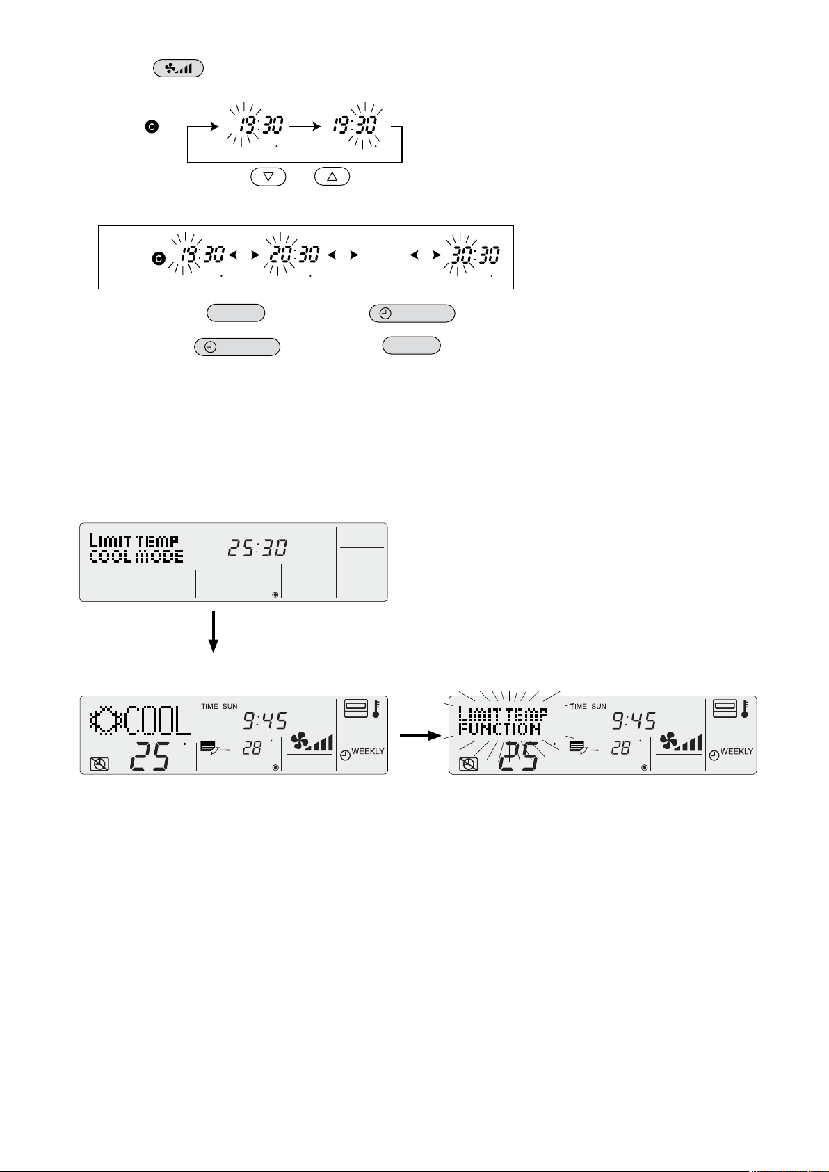
(5) Press the button to select lower limit or upper limit.
Display
С С С
C
C
C
C
C C
Lower limit blinks. Upper limit blinks.
[Display
(6) Press the [TEMP] buttons (
]
and ) to set the desired temperature setting range.
[Setting example for lower limit]
(7) While pressing the
MODE
button, press the
ON/OFF
button for 2 seconds to return to normal mode. Setting is
now complete.
* If you press the
ON/OFF
button before the
MODE
button, the settings you have made will be cancelled.
* If an attempt is made to set a temperature outside the range when the temperature range limit function is in use, “LIMIT
TEMP FUNCTION” will blink.
Display example when the temperature range limit function is in use
If employees tend to lower the temperature excessively in the office without permission, set the temperature setting range for
cool/dry mode
to 25 °C - 30 °C.
Setting
Even if someone who feels hot tries to press remote the controller’s
buttons to lower the temperature below 24 °C, or lower…
LIMIT TEMP
FUNCTION
blinks and the command is not accepted.
19
(1)
(2)
(3)
(4)
(5)
4.3 Basic Functions Setting
CHANGE
LANGUAGE
FUNCTION
SELECTION
MODE
SELECTION
DISP MODE
SETTING
CONTROLLER
MAIN
CONTROLLER
SUB
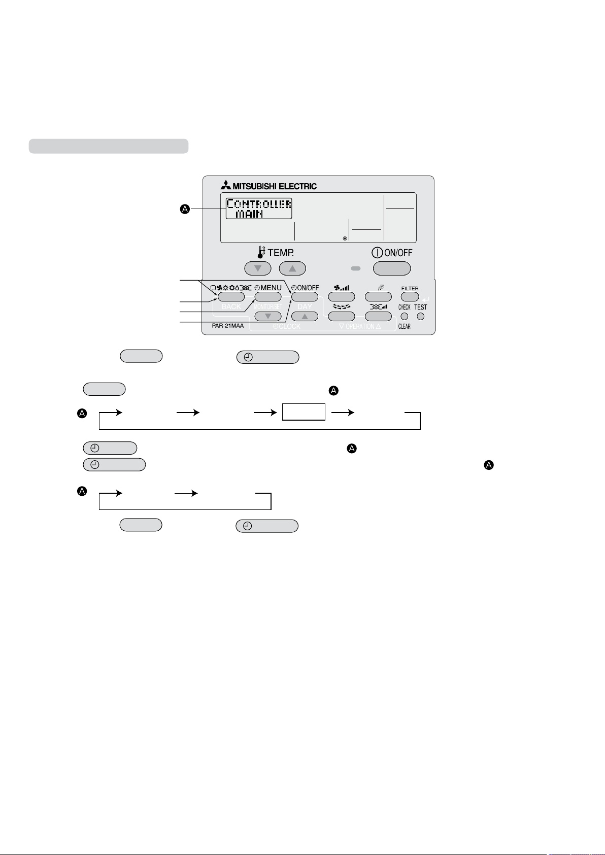
4.3.1 Remote Controller Main/Sub Setting
When using 2 remote controllers, they must be designated as the main and sub remote controllers.
The following settings can be made.
MAIN (default)
1
SUB : The
2
To Change the Main/Sub Setting
: The remote controller is set as the main controller.
remote controller is set as the sub controller.
Display example
(1) While pressing the
tion selection mode.
(2) Press the
[Display
(3) Press the
(4) Press the
[Display
MODE
]
MENU
ON/OFF
]
(5) While pressing the
MODE
button until
button, press the
MODE
SELECTION
appears on the screen (at ).
ON/OFF
button for 2 seconds to activate the remote controller’s func-
button to select “CONTROLLER” on the screen (at ).
button to select “CONTROLLER MAIN” or “CONTROLLER SUB” on the screen (at ).
MODE
button, press the
ON/OFF
button for 2 seconds to return to normal mode.
20
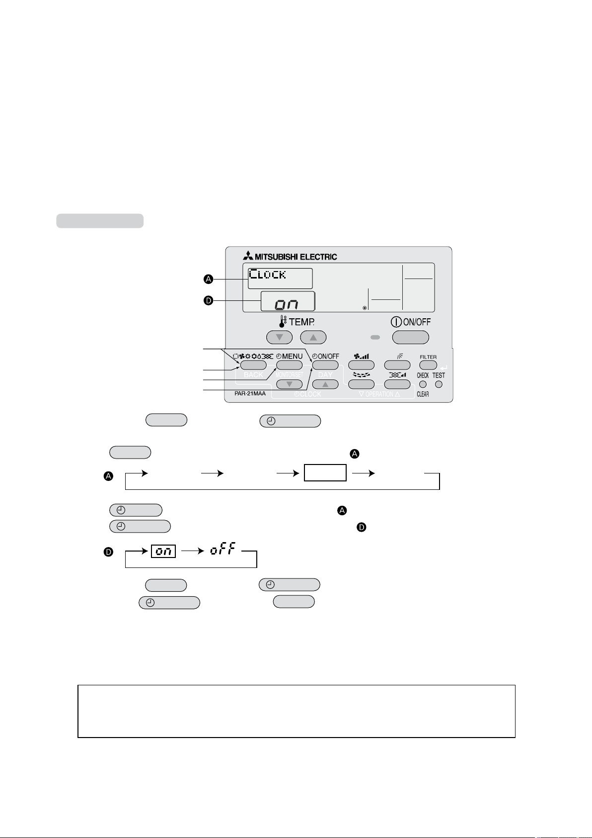
(1)
(2)
(3)
(4)
(5)
4.3.2 Timer function setting (Weekly timer/Auto off timer/Simple timer)
CHANGE
LANGUAGE
FUNCTION
SELECTION
MODE
SELECTION
DISP MODE
SETTING
The following settings can be made.
Weekly T
1
Auto Of
2
Simple Timer
3
Timer
4
* If the clock function is disabled (OFF), “Weekly Timer” cannot be selected.
Clock function setting
The following settings can be made.
ON (default)
1
OFF : The
2
* If “OFF” is selected to disable the clock function, the weekly timer cannot be used to make day of the week/time settings.
To use the weekly timer to set the day of the week and time, the clock function must be set to “ON” (default).
To Use the Clock
imer (default) : The weekly timer can be used.
f Timer : The auto off timer can be used.
: The simple timer can be used.
Mode Off : Timer mode cannot be used.
: The clock function can be used.
clock function cannot be used.
Display example
(1) While pressing the
MODE
button, press the
ON/OFF
button for 2 seconds to activate the remote controller’s func-
tion selection mode.
(2) Press the
[Display
(3) Press the
(4) Press the
[Display
(5) While pressing the
* If you press the
Day of the week and time setting
The day of the week and time can be set and changed.
MODE
]
MENU
ON/OFF
]
button until
button to select “CLOCK” on the screen (at ).
MODE
ON/OFF
MODE
SELECTION
appears on the screen (at )
button so that “ON” appears on the screen (at ).
button, press the
button before the
ON/OFF
MODE
button for 2 seconds to return to normal mode.
button, the settings you have made will be cancelled.
[The time can be set in 1-minute increments.]
Notes
• This
setting is not possible if the clock function is disabled by the function setting.
• The day of the week and time are not displayed if the clock function is disabled by function selection.
• This setting is not possible if the simple timer or auto off timer has been selected.
21
 Loading...