

Page 1

GROUP 0
GENERAL
CONTENTS
0-1
HOW TO USE THIS MANUAL. . . . . . 0-2
PRECAUTIONS BEFORE SERVICE. 0-2
PROTECTING THE VEHICLE . . . . . . . . . . 0-2
DOING SERVICE WORK IN GROUPS OF TWO
OR MORE MECHANICS . . . . . . . . . . . . . . 0-2
REMOVAL AND DISASSEMBLY . . . . . . . . 0-2
SPECIAL TOOLS . . . . . . . . . . . . . . . . . . . . 0-3
PARTS TO BE REPLACED . . . . . . . . . . . . 0-3
PARTS . . . . . . . . . . . . . . . . . . . . . . . . . . . . 0-3
TUBES AND OTHER RUBBER PARTS . . . 0-3
LUBRICANTS . . . . . . . . . . . . . . . . . . . . . . . 0-3
BRAKE FLUID . . . . . . . . . . . . . . . . . . . . . . . 0-3
SERVICING THE ELECTRICAL SYSTEM . 0-4
APPLICATION OF ANTI-CORROSION AGENTS
AND UNDERCOATS . . . . . . . . . . . . . . . . . . 0-4
PRE-INSPECTION CONDITION . . . . . . . . . 0-4
VEHICLE WASHING . . . . . . . . . . . . . . . . . . 0-4
MULTI USE TESTER (M.U.T.-III) SUB
ASSEMBLY . . . . . . . . . . . . . . . . . . . . . . . . . 0-4
IN ORDER TO PREVENT VEHICLES
FROM FIRE . . . . . . . . . . . . . . . . . . . . . . . . . 0-5
ENGINE OILS . . . . . . . . . . . . . . . . . . . . . . . 0-5
Page 2
0-2
HOW TO USE THIS MANUAL
HOW TO USE THIS MANUAL
This manual contains Pre-delivery inspection and
Periodic inspection and maintenance.
PRECAUTIONS BEFORE SERVICE
GENERAL
M6000000100026
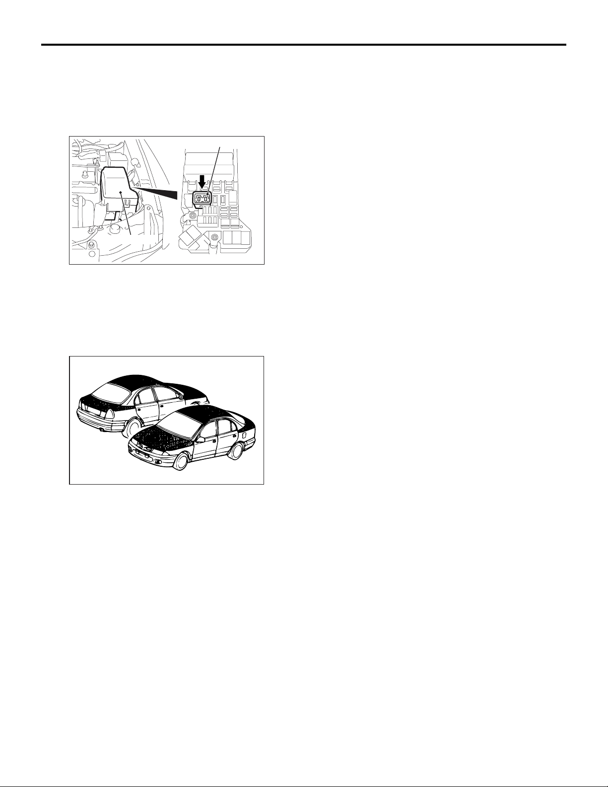
Group 0 and 1 have the contents for all vehicle models, and Group 2 has contents for the relevant vehicle models.
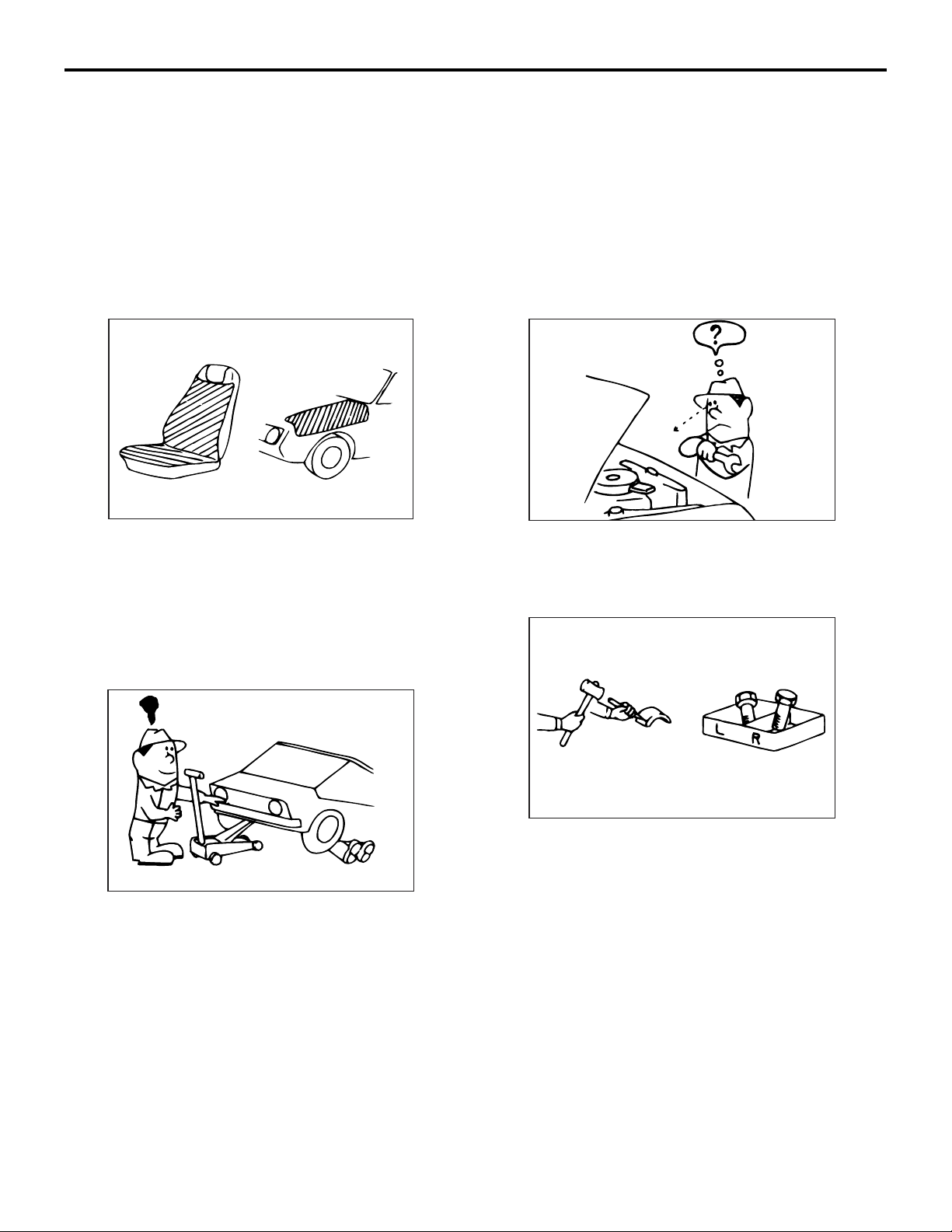
PROTECTING THE VEHICLE
M6001000100029
AC305590
If there is a likelihood of damaging interior or exterior
parts during service operations, protect them with
suitable covers (such as seat covers, fender covers,
etc.).
DOING SERVICE WORK IN GROUPS OF TWO OR MORE MECHANICS
M6001000200026
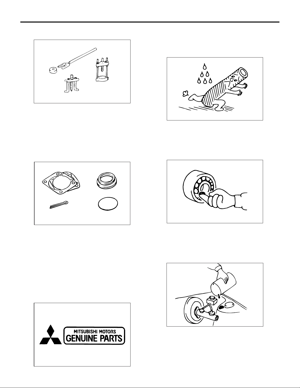
REMOVAL AND DISASSEMBLY
M6001000300023
AC305591
When checking a malfunction, find the cause of the
problem. If it is determined that removal and/or dis
assembly is necessary, perform the work by following
the procedures contained in this manual.
-
AC305283
If the service work is to be done by two or more
mechanics working together, all the mechanics
involved should take safety into consideration while
they work.
AC305592
If punch marks or mating marks are made to avoid
error in assembly and facilitate the assembly work,
be sure to make them in locations which will have no
detrimental effect on performance and/or appear
ance. If an area having many parts, similar parts,
and/or parts which are symmetrical right and left is
disassembled, be sure to arrange the parts so that
they do not become mixed during the assembly proc
ess.
1. Arrange the parts removed in the proper order.
2. Determine which parts are to be reused and which
are to be replaced.
3. If bolts, nuts, etc., are to be replaced, be sure to
use only the exact size specified.
-
Page 3
GENERAL
PRECAUTIONS BEFORE SERVICE
0-3
SPECIAL TOOLS
M6001000400031
AC305593
If other tools are substituted for the special tools to
do service of repair work, there is the danger that
vehicle parts might be damaged, or the technician
might be injured; therefore, be sure to use the spe
cial tool whenever doing any work for which the use
of one is specified.
PARTS TO BE REPLACED
M6001000500027
When replacing parts, use MITSUBISHI genuine
parts.
TUBES AND OTHER RUBBER PARTS
M6001000700021
AC305595
Be careful to avoid spilling any petrol, oil, etc.,
because if it adheres to any tubes or other rubber
parts, they might be adversely affected.
LUBRICANTS
M6001000800028
AC305594
If any of the following parts are removed, they must
be replaced with new parts.
• Oil seals
• Gaskets (except rocker cover gasket)
• Packings
• O-rings
• Lock washers
• Split pins
• Self-locking nuts
PARTS
M6001000600024
AC305596
In accordance with the instructions in this manual,
apply the specified lubricants in the specified loca
-
tions during assembly and installation.
BRAKE FLUID
M6001000900025
AC305285
Be careful to avoid spilling any brake fluid, because if
it adheres to the vehicle body, the paint coat might be
discoloured.
AC305284
Page 4
0-4
GENERAL
PRECAUTIONS BEFORE SERVICE
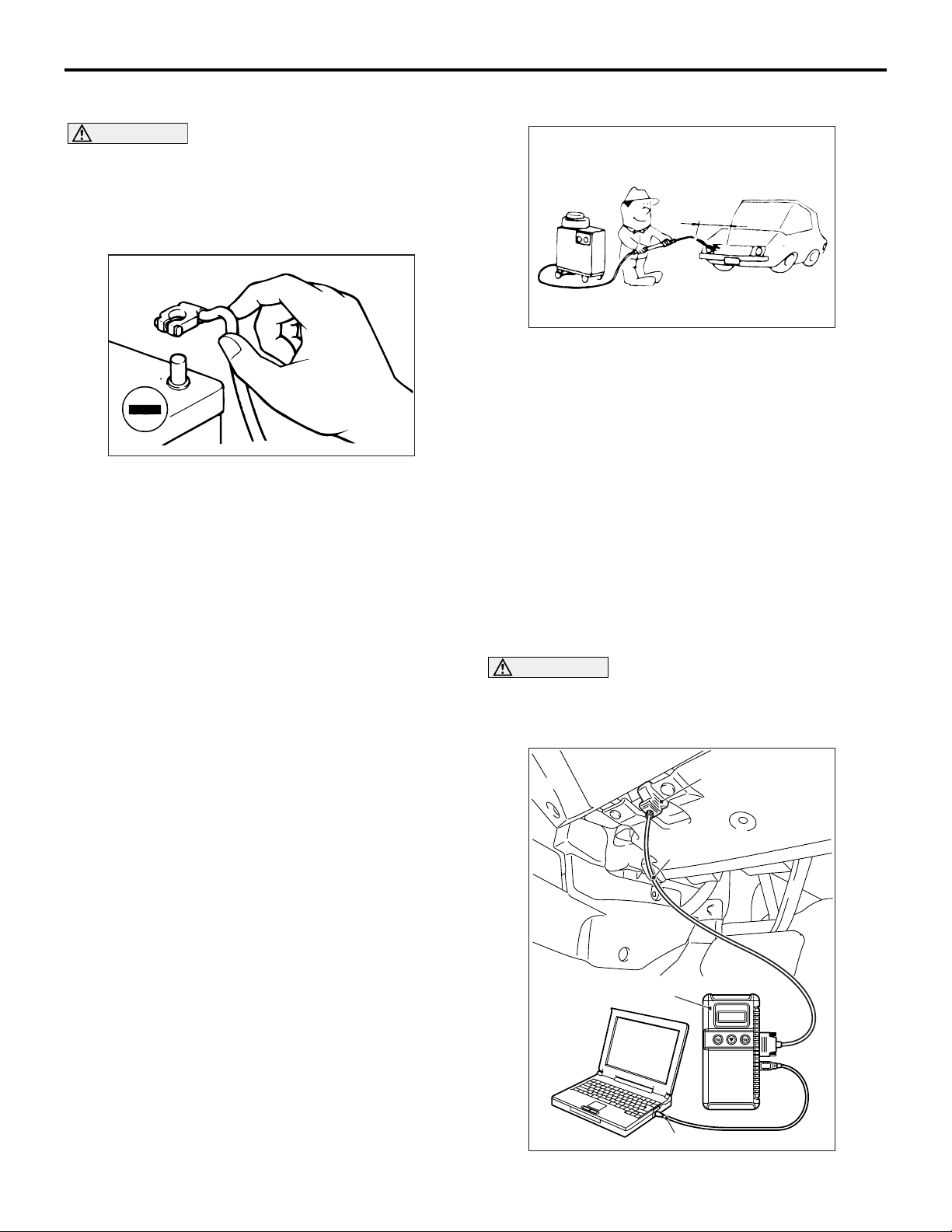
SERVICING THE ELECTRICAL SYSTEM
M6001001000081
CAUTION
Before connecting or disconnecting the negative
(-) cable, be sure to turn off the ignition switch
and the lighting switch. (If this is not done, there
is the possibility of semiconductor parts being
damaged.)
ACX00880
AD
Before replacing a component related to the electrical system and before undertaking any repair procedures involving the electrical system, be sure to first
disconnect the negative (-) cable from the battery in
order to avoid damage caused by short-circuiting.
APPLICATION OF ANTI-CORROSION AGENTS AND UNDERCOATS
M6001001100022
If oil or grease gets onto the oxygen sensor, it will
cause a drop in the performance of the sensor.
Cover the oxygen sensor with a protective cover
when applying anti-corrosion agents and undercoats.
PRE-INSPECTION CONDITION
M6001001200041
"Pre-inspection condition" refers to the condition that
the vehicle must be in before proper engine inspec
tion can be carried out. If you see the words "Set the
vehicle to the pre-inspection condition". In this man
ual, it means to set the vehicle to the following condition.
• Engine coolant temperature: 80 to 90° C
• Lamps, electric cooling fan and all accessories:
OFF
• M/T: Neutral
• A/T: P range
-
-
VEHICLE WASHING
M6001001300123
Approximately
40 cm or more
AC300832
AC
If high-pressure car-washing equipment or steam
car-washing equipment is used to wash the vehicle,
be sure to note the following information in order to
avoid damage to plastic components, etc.
• Spray nozzle distance: Approximately 40 cm or
more
• Spray pressure: 3,900 kPa or less
• Spray temperature: 82°C or less
• Time of concentrated spray to one point: within
30 sec.
MULTI USE TESTER (M.U.T.-III) SUB ASSEMBLY
M6001001900169
Refer to the "M.U.T.-III OPERATING INSTRUCTIONS" for instructions on handling the M.U.T.-III.
CAUTION
Turn the ignition switch to the LOCK (OFF) position before connecting or disconnecting the
M.U.T.-III.
Diagnosis connector
MB991910
MB991824
MB991827
AC505420
AB
Page 5

GENERAL
PRECAUTIONS BEFORE SERVICE
0-5
Connect the M.U.T.-III to the diagnosis connector as
shown in the illustration.
IN ORDER TO PREVENT VEHICLES FROM FIRE
M6001001500064
"Improper installation of electrical or fuel related parts
could cause a fire. In order to retain the high quality
and safety of the vehicle, it is important that any
accessories that may be fitted or modifica
tions/repairs that may be carried out which involve
the electrical or fuel systems, must be carried out in
accordance with MMC's information/Instructions".
-
ENGINE OILS
M6001001600061
HEALTH WARNING
Prolonged and repeated contact with mineral oil will
result in the removal of natural fats from the skin,
leading to dryness, irritation and dermatitis. In addi
tion, used engine oil contains potentially harmful contaminants which may cause skin cancer. Adequate
means of skin protection and washing facilities must
be provided.
-
RECOMMENDED PRECAUTIONS
The most effective precaution is to adapt working
practices which prevent, as far as practicable, the
risk of skin contact with mineral oils, for example by
using enclosed systems for handling used engine oil
and by degreasing components, where practicable,
before handling them.
Other precautions:
• Avoid prolonged and repeated contact with oils,
particularly used engine oils.
• Wear protective clothing, including impervious
gloves where practicable.
• Avoid contaminating clothes, particularly underpants, with oil.
• Do not put oily rags in pockets, the use of overalls
without pockets will avoid this.
• Do not wear heavily soiled clothing and
oil-impregnated foot-wear. Overalls must be
cleaned regularly and kept separately from per
sonal clothing.
• Where there is a risk of eye contact, eye protection should be worn, for example, chemical goggles or face shields; in addition an eye wash
facility should be provided.
• Obtain first aid treatment immediately for open
cuts and wounds.
• Wash regularly with soap and water to ensure all
oil is removed, especially before meals (skin
cleansers and nail brushes will help). After clean
ing, the application of preparations containing
lanolin to replace the natural skin oils is advised.
• Do not use petrol, kerosine, diesel fuel, gas oil,
thinners or solvents for cleaning skin.
• Use barrier creams, applying them before each
work period, to help the removal of oil from the
skin after work.
• If skin disorders develop, obtain medical advice
without delay.
-
-
Page 6

NOTES
Page 7

GROUP 1
PRE-DELIVERY
INSPECTION
CONTENTS
1-1
NOTES CONCERNING ENTRIES . . . 1-3
PAINTWORK TERMS . . . . . . . . . . . . 1-5
FIRST STEP . . . . . . . . . . . . . . . . . . . . 1-6
1. CONNECTION OF DARK CURRENT
CONNECTOR . . . . . . . . . . . . . . . . . . . . . . . 1-6
BODY . . . . . . . . . . . . . . . . . . . . . . . . . 1-6
2. WRAP FILM . . . . . . . . . . . . . . . . . . . . . . 1-6
3. EXTERIOR . . . . . . . . . . . . . . . . . . . . . . . 1-7
4. OPERATION OF DOOR LOCKING SYSTEMS
AND DOOR HINGES . . . . . . . . . . . . . . . . . 1-8
5. OPERATION OF DOOR MIRRORS,
WINDOWS AND SUNROOF . . . . . . . . . . . 1-8
UNDER HOOD . . . . . . . . . . . . . . . . . . 1-9
6. ENGINE OIL LEVEL . . . . . . . . . . . . . . . . 1-9
7. BRAKE MASTER CYLINDER FLUID LEVEL 1-9
8. CLUTCH MASTER CYLINDER FLUID LEVEL 1-9
9. WASHER FLUID LEVEL. . . . . . . . . . . . . 1-9
10. BATTERY CONDITION AND
CONNECTIONS . . . . . . . . . . . . . . . . . . . . . 1-9
11. POWER STEERING FLUID LEVEL . . . 1-9
12. ELECTRICAL WIRING . . . . . . . . . . . . . 1-10
UNDER VEHICLE . . . . . . . . . . . . . . . 1-10
13. TYRE AND SPARE TYRE PRESSURES 1-10
14. SUSPENSION SYSTEM. . . . . . . . . . . . 1-10
15. STEERING LINKAGE AND SPLIT PINS 1-11
16. UNDER BODY. . . . . . . . . . . . . . . . . . . . 1-11
BEFORE ROAD TEST . . . . . . . . . . . . 1-11
17. SEAT ADJUSTERS AND SEATBACK
LATCHES . . . . . . . . . . . . . . . . . . . . . . . . . . 1-11
18. INHIBITOR SWITCH . . . . . . . . . . . . . . . 1-11
19. IDLE CONTROL KNOB . . . . . . . . . . . . . 1-11
20. INSTRUMENT PANEL CONTROLS . . . 1-12
21. METERS, GAUGES, WARNING LAMPS
AND INDICATION LAMPS . . . . . . . . . . . . . 1-12
22. AIR CONDITIONER, HEATER AND
DEFROSTER SYSTEM. . . . . . . . . . . . . . . . 1-12
23. WIPERS AND WASHERS. . . . . . . . . . . 1-12
24. OPERATION OF SERVICE BRAKES AND
PARKING BRAKES. . . . . . . . . . . . . . . . . . . 1-13
25. CLUTCH OPERATION . . . . . . . . . . . . . 1-13
26. OPERATION OF SEAT BELTS, SHOULDER
BELTS AND RETRACTORS . . . . . . . . . . . . 1-13
ROAD TEST . . . . . . . . . . . . . . . . . . . . 1-14
27. ENGINE PERFORMANCE AND EXHAUST
GAS . . . . . . . . . . . . . . . . . . . . . . . . . . . . . . . 1-14
28. TRANSMISSION IN ALL RANGES . . . . 1-14
29. BRAKES . . . . . . . . . . . . . . . . . . . . . . . . 1-14
30. STEERING CONTROL . . . . . . . . . . . . . 1-14
31. VIBRATION AND RATTLES . . . . . . . . . 1-15
32. ELECTRICAL EQUIPMENT . . . . . . . . . 1-15
Continued on next page
Page 8

1-2
AFTER ROAD TEST . . . . . . . . . . . . . 1-15
33. IDLE SPEED . . . . . . . . . . . . . . . . . . . . . 1-15
34. IGNITION TIMING. . . . . . . . . . . . . . . . . 1-15
35. RADIATOR COOLANT LEVEL . . . . . . . 1-15
36. HOSES, FLUID LINES AND CONNECTIONS
LOCATED UNDER HOOD . . . . . . . . . . . . . 1-16
37. MANUAL TRANSMISSION AND TRANSFER
(4WD) OIL LEVEL. . . . . . . . . . . . . . . . . . . . 1-16
38. AUTOMATIC TRANSMISSION FLUID
LEVEL . . . . . . . . . . . . . . . . . . . . . . . . . . . . . 1-16
39. ENGINE, TRANSMISSION, STEERING
GEAR BOX AND DIFFERENTIAL FOR LEAKS 1-16
40. FRONT AND REAR DIFFERENTIAL OIL
LEVELS . . . . . . . . . . . . . . . . . . . . . . . . . . . . 1-16
41. HOSES, FLUID LINES AND CONNECTIONS
LOCATED UNDER VEHICLE . . . . . . . . . . . 1-17
FINAL STEPS . . . . . . . . . . . . . . . . . . . 1-17
42. HEADLAMP AIMING . . . . . . . . . . . . . . . 1-17
43. EQUIPMENT . . . . . . . . . . . . . . . . . . . . . 1-17
44. EXTERIOR AND INTERIOR . . . . . . . . . 1-17
45. OWNER INSTRUCTIONS . . . . . . . . . . . 1-17
Page 9

PRE-DELIVERY INSPECTION
NOTES CONCERNING ENTRIES
1-3
NOTES CONCERNING ENTRIES
M6010100100132
This section describes the details and the inspection methods employed for the pre-delivery inspection of
vehicles.
The inspection should be conducted according to the sequence described in the TABLE OF PRE-DELIVERY
INSPECTION.
Inspection methods are described following the TABLE OF PRE-DELIVERY INSPECTION.
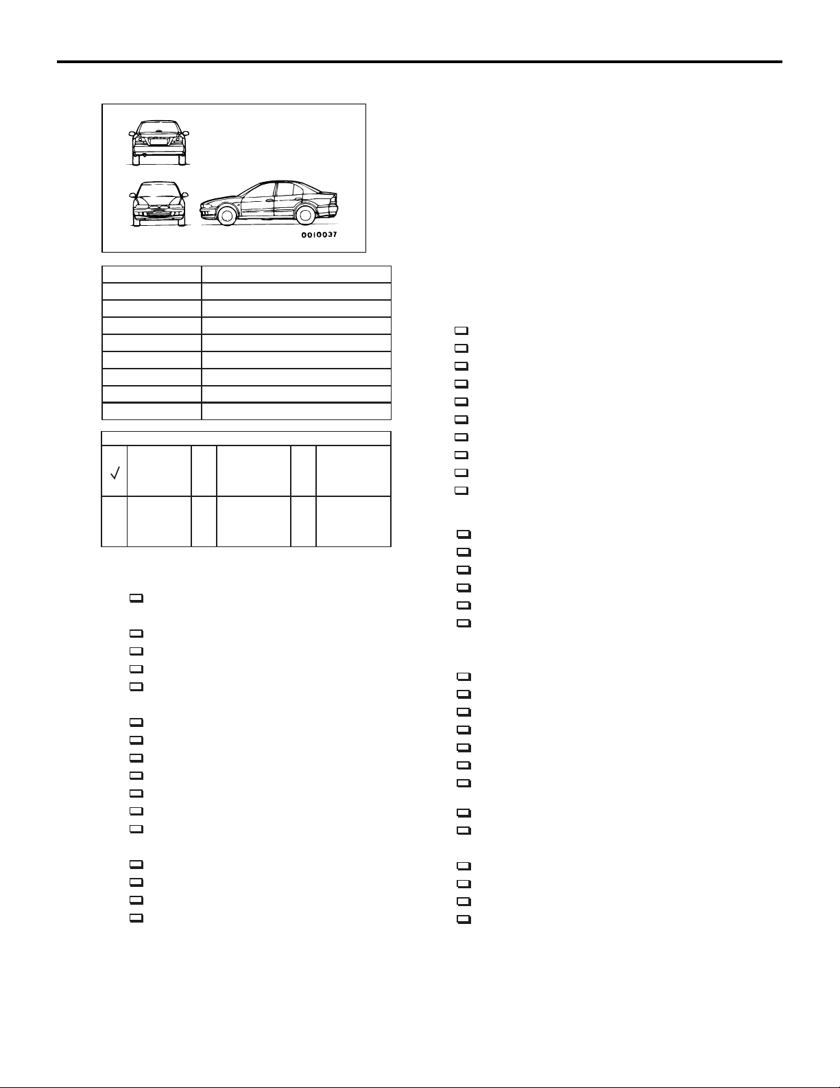
NOTE: The spaces for model, C/# (Chassis number), E/# (engine number), aggregate distance travelled in
kilometres (miles), date of inspection, name of person conducting the inspection, and body colour must be
completed without fail.
NOTE: The spaces for place of inspection, and name of owner should be completed as required.
Page 10
1-4
PRE-DELIVERY INSPECTION
NOTES CONCERNING ENTRIES
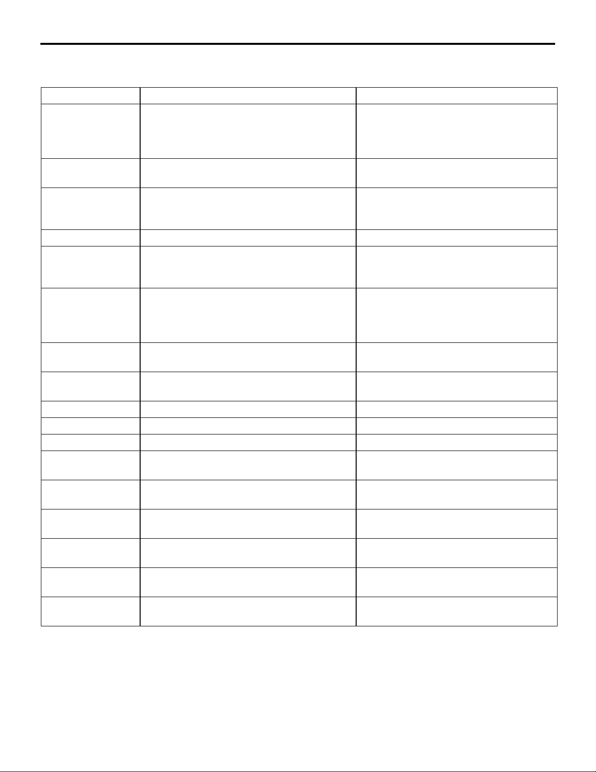
TABLE OF PRE-DELIVERY INSPECTION
Model
Chassis number
Engine number
Distance Travelled km
Owner
Date of inspection
Place of inspection
Inspector
Body colour
Symbols to be used
Good A T
Needs
cleaning
INSPECTION PROCEDURE
First Step
1. Connection of the dark current connector
Body
2. Wrap film
3. Exterior
4. Operation of door locking systems and door hinges
5. Operation of door mirrors, windows and sunroof
Under Hood
6. Engine oil level
7. Brake master cylinder fluid level
8. Clutch master cylinder fluid level
9. Washer fluid level
10. Battery condition and connections
11. Power steering fluid level
12. Electrical wiring
Under Vehicle
13. Tyre and spare tyre pressures
14. Suspension system
15. Steering linkage and split pins
16. Under body
Needs
adjustment
Needs
replenishment
L X C
of lubricant,
water, etc.
Needs
retightening
Needs
replenishment
of repair
Before Road Test
17. Seat adjusters and seat back latches
18. Choke system and inhibitor switch
19. Idle control knob
20. Instrument panel controls
21. Meters, gauges, warning lamps and indication lamps
22. Air conditioning, heater and defroster systems
23. Wipers and washers
24. Operation of service brakes and parking brakes
25. Clutch operation
26. Operation of seat belts, shoulder belts and retractors
Road Test
27. Engine performance and exhaust gas
28. Transmission in all ranges
29. Brakes
30. Steering control
31. Vibration and rattles
32. Electrical equipment
After Road Test
33. Idle speed
34. Ignition timing
35. Radiator coolant level
36. Hoses, fluid lines and connections located under hood
37. Manual transmission and transfer (4WD) oil level
38. Automatic transmission fluid level
39. Engine, transmission, steering gear box and
differential for leaks
40. Front and rear differential oil levels
41. Hoses, fluid lines and connections located under vehicle
Final Steps
42. Headlamp aiming
43. Equipment
44. Exterior and interior
45. Owner instructions
AC306353AC401525
Page 11
PRE-DELIVERY INSPECTION
PAINTWORK TERMS
PAINTWORK TERMS
Term Definition Remark
Blister A raised bubble in the paint (from the base
or the undercoat) caused by abnormal
moisture. The bubble may contain either
water or air.
1-5
M6010200100140
Change in tone The colour tone of the painted surface is not
uniform.
Contact mark A mark on the painted surface as a result of
contact by hands or clothing at the time of
paint application.
Crack A crack in the painted surface. Cracks may be either shallow or deep.
Dirt in paintwork Rough surface resulting from foreign
material in the paint or from dust deposited
on wet paint during painting or storage.
Filed or earth
traces
Orange peel The painted surface has the appearance of
Peeling The paint flakes off (partly or over a wide
Pin holes Tiny holes in the painted surface.
Runs A visible trickle of dried paint on the surface. Either undercoat or top-coat.
Scratches Scratches on the painted surface.
Deep scratches in sheet metal surface,
resulting from improper use of buffer or
sander, are not completely covered, and are
visible through paint coating.
an orange peel.
area).
Including wrong colour, discoloration and
decolouration.
The peeling may be minor, medium, or
major.
Shrink The painted surface "shrinks", causing
wrinkles.
Smears Spots of soot or other material deposited on
the painted surface.
Spray mist The painted surface includes fine particles of
other paint.
Uneven lustre The lustre of the painted surface is not
uniform.
Uneven metallic
dispersion
Visibly incomplete
topcoating
The metallic dispersion of the painted
surface is not uniform.
A part of the undercoating visible.
Including stains and water spots.
Page 12
1-6
PRE-DELIVERY INSPECTION
FIRST STEP
FIRST STEP
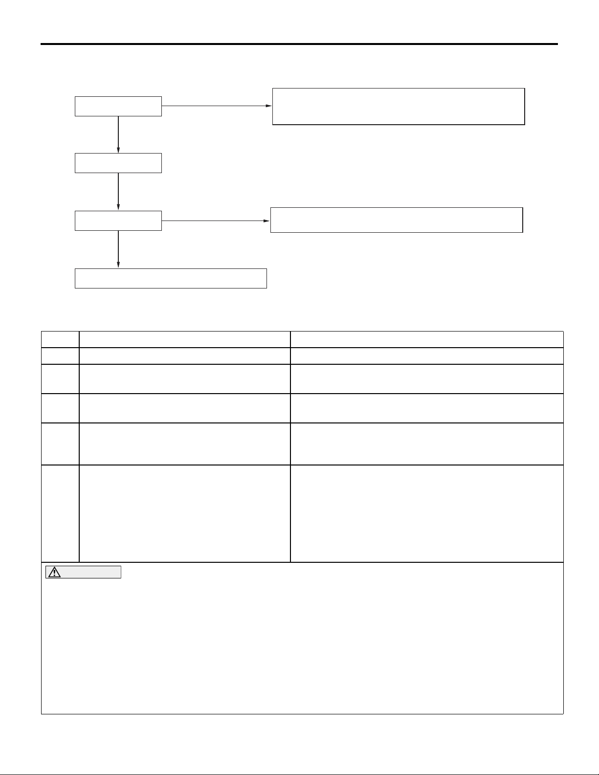
1. CONNECTION OF DARK CURRENT CONNECTOR
M6010300100170
CONNECTING PROCEDURE
Storage connector
Relay box
AC608836
AB
2. WRAP FILM
M6010400100100
Press down the storage connector.
BODY
To protect the exterior finish of vehicles prior to
dealer delivery, a protective coating is used. The
coating is a thin white resin film. It is applied to all
painted exterior horizontal surfaces of the vehicle
and is held in place with a tacky adhesive backing.
AC305606
Page 13
REMOVAL PROCEDURE
Wrap film removal
Water washing
PRE-DELIVERY INSPECTION
BODY
Peel off slowly from corners keeping parallel to the body. When
the body temperature is high, lower it to 50ºC or less by
sprinkling water so that adhesive may not remain on the body.
1-7
Cleaning of border
Disposal of removed film: Burning is appropriate
Wipe-off by kerosene or white gasoline, etc.
If it is considerably visible, use polishing compound.
AC306352
AB
Wrapping work
No. Process Operation Content
1 Continuous peeling of film The film is peeled off.
2 Water rinse Sand and dust are removed from the vehicle body and it
is dried thoroughly.
3 Parts where the film is to be reapplied are
checked.
4 Treatment of parts where film is to be
reapplied.
There should be no leftover adhesive, swelling or
discoloration of the paint film, or other defects.
Treat the defects on the parts where film is to be
reapplied. If a solvent is used to remove leftover
adhesive, wipe off the solvent thoroughly.
5 Reapplication
1. Basically, the parts where the film is to be applied
should be the same as the film that is to be applied.
2. Apply the film from the lower portion of the body,
working upward progressively. Apply pressure using
a plastic squeegee or similar tool.
3. As necessary, cut the film at the various parts such as
windshield washer nozzles, hood and trunk lid.
CAUTION
• Apply the film with the body at a temperature of 10 − 40° C. (Workability is good in this temperature
range.)
• If the outside surface of the film (the side with no adhesive) is brought into direct contact with the
paint film and left in that state, it may result in loss of paint gloss, so make sure the film does not
get folded under or otherwise make contact with the paint film.
• Air bubbles and wrinkles do not have a particularly bad influence on the pain film, but every effort
should be made to prevent air bubbles from being trapped under the film by applying pressure
from the centre of the film outward toward the edges during application.
• To prevent intrusion of rainwater, be sure to press down the overlapping portions and cut ends of
the film securely.
Page 14
1-8
PRE-DELIVERY INSPECTION
BODY
3. EXTERIOR
M6010400200226
1. Visually inspect the entire exterior.
(1) Paint condition
(2) Corrosion, scratches
(3) Bent edges, dented panels
2. Coated surfaces maintenance
Touch up minor paint chips and flaws.
(Refer to paintwork terms)
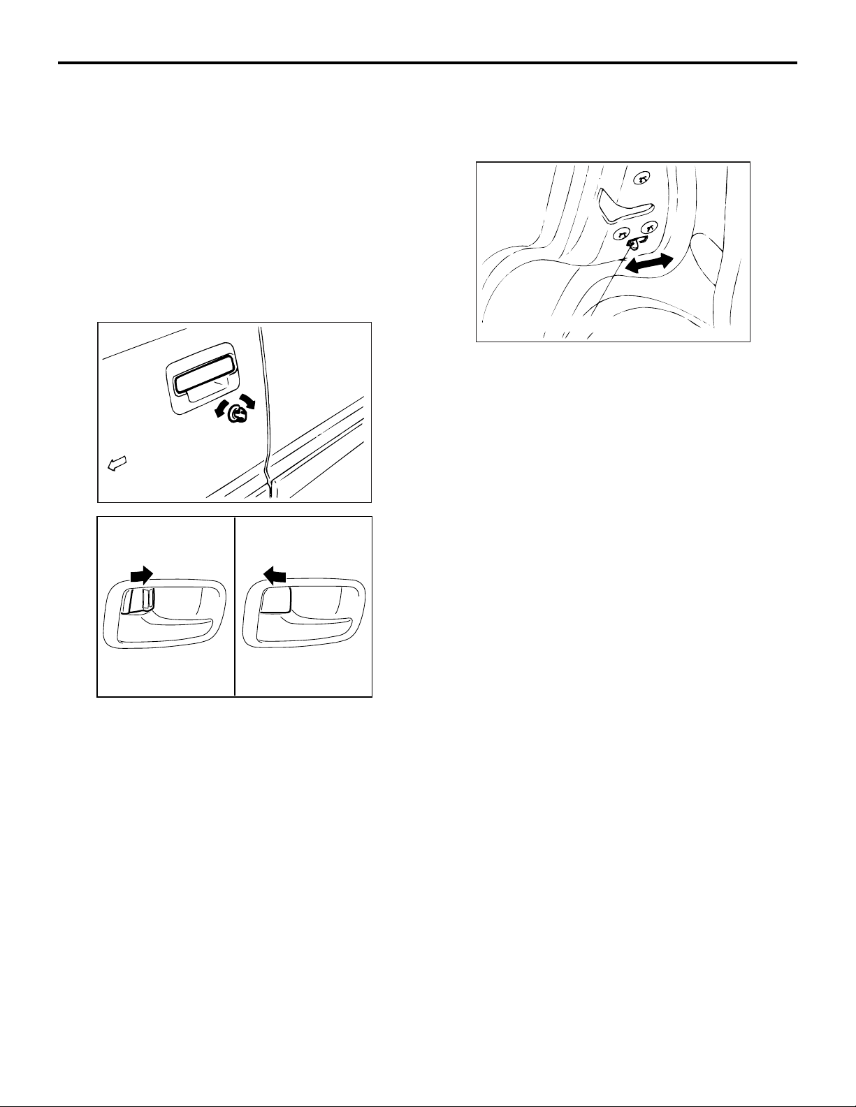
4. OPERATION OF DOOR LOCKING
SYSTEMS AND DOOR HINGES
M6010400300137
Front
AC305608
AB
6. Verify that all doors can be locked by the lock
buttons.
NOTE: Adjust and lubricate the door latches, strikers
and locks as required.
Child-protection knob
AC305610
AB
7. Verify that the rear doors can't be opened by the
inner door handle when the child protection knob
at the end of the door is shifted to the "LOCK"
position with the inside lock plunger raised.
NOTE: Set the lock to the "FREE" position on child
protection of both rear doors. (For four door models)
5. OPERATION OF DOOR MIRRORS,
WINDOWS AND SUNROOF
M6010400400112
1. Door mirrors
AC210253
AB
1. Open each door to check the release mechanism
and ease of operation.
2. Close the door to check the latch and striker.
3. Open the door, operate the lock lever and close
the door to check the lock.
4. Partially close the door to check the open-door
detent.
5. Unlock each door with the key to check lock
operation.
Check that the mirror operate properly.
2. Door windows
Close all door windows to the fully closed position
to check ease of operation.
3. Power windows
Check that the door windows operate when the
respective switches are operated. Check that
when the lock switches are depressed, the
respective door windows can no more be opened
or closed.
4. Slide window
Close the slide window to the fully closed position
to check operation.
5. Sunroof
Close the sunroof to the fully closed position to
check operation.
Page 15
PRE-DELIVERY INSPECTION
UNDER HOOD
UNDER HOOD
1-9
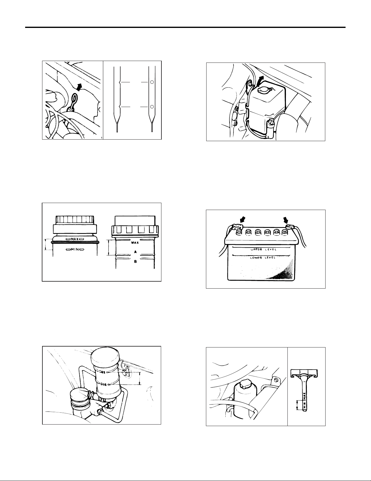
6. ENGINE OIL LEVEL
M6010500100196
MAX
MIN
AC702169
Check that the oil level is between "MAX" and "MIN".
If it is at or below MIN, add the necessary amount of
the specified engine oil referring to GROUP 2, Peri
-
odic Inspection and Maintenance.
7. BRAKE MASTER CYLINDER FLUID
LEVEL
M6010500200148
9. WASHER FLUID LEVEL
M6010500400108
AC305614
Check the fluid level; if it is low, replenish the washer
fluid.
1. Windshield washer reservoir
2. Rear window washer reservoir
10. BATTERY CONDITION AND CONNECTIONS
M6010500500042
AC702028
Check the fluid level.
If it is below the "MIN" mark, replenish fresh brake
fluid up to the "MAX" mark.
Specified Brake Fluid: DOT3 or DOT4
8. CLUTCH MASTER CYLINDER FLUID
LEVEL
Check the fluid level.
If it is below the "MIN" mark, replenish fresh brake
fluid up to the "MAX" mark.
Specified Brake Fluid: DOT3 or DOT4
M6010500300026
AC305613
AC305615
Inspect the battery connections. Verify that they are
tightened.
NOTE: Do not wipe the lubricant from the battery
posts and cable clamps.
11. POWER STEERING FLUID LEVEL
M6010500600072
AC305616
1. Check that the fluid level is between "MAX" and
"MIN".
Page 16
1-10
PRE-DELIVERY INSPECTION
UNDER VEHICLE
2. If the fluid is added, start the engine and turn the
steering wheel from stop to stop several times to
expel air from the system.
Specified gear oil: Automatic transmission
fluid DEXRON III or DEXRON II
12. ELECTRICAL WIRING
M6010500700024
AC305617
UNDER VEHICLE
1. Each electrical wiring harness and connector
(1) Check each harness to be correctly routed
and securely clipped.
(2) Confirm that all connections are tight.
2. Ignition cable
Be sure that all ignition cables are firmly attached
to the spark plugs, distributor cap (or crank angle
sensor) and ignition coil.
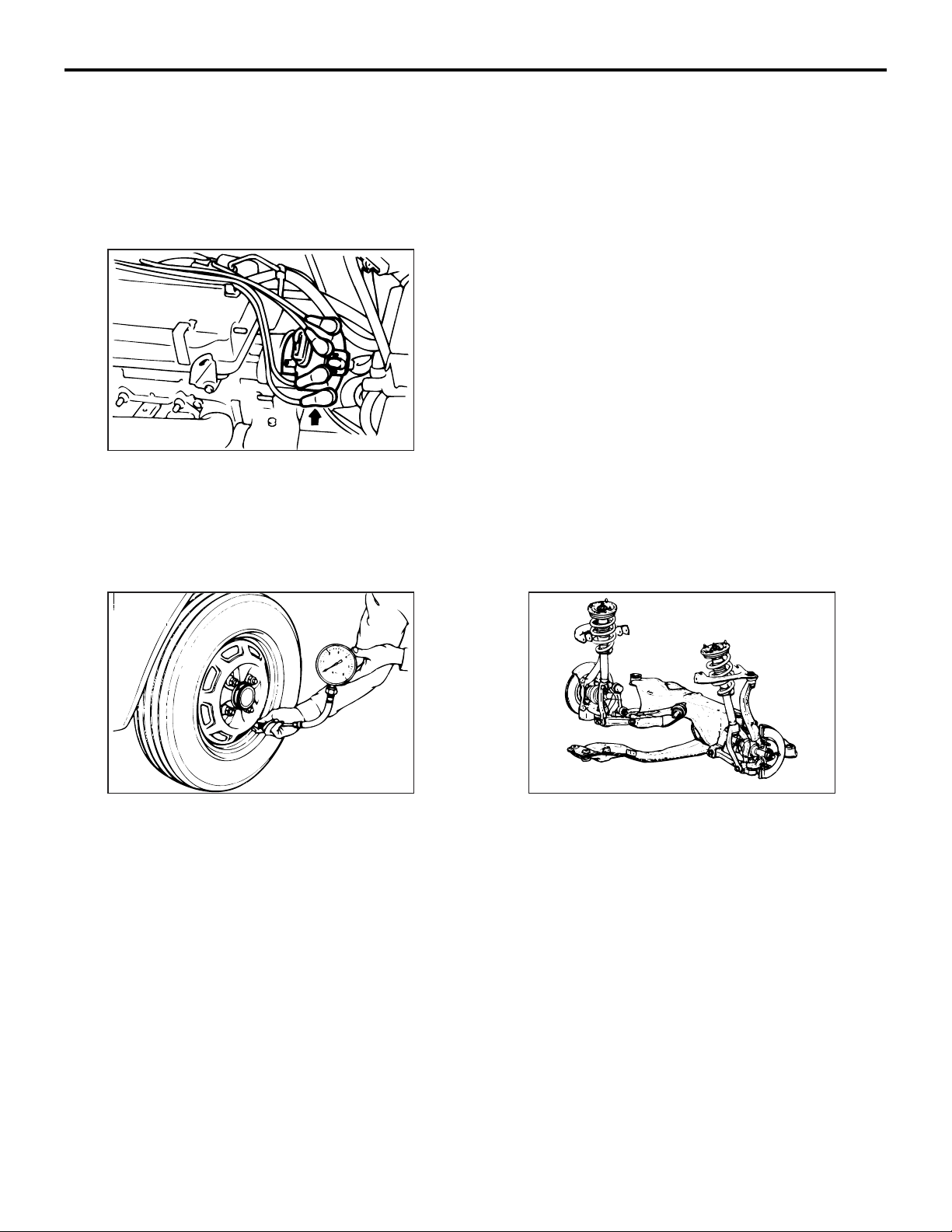
13. TYRE AND SPARE TYRE PRESSURES
M6010600100041
AC305618 AC305609
1. Tyre specification
Check the correct tyre specification.
2. Tyre pressures
Adjust each tyre pressure.
NOTE: Recommended pressure is shown on the
tyre pressure label.
3. Valve stem extensions
Verify that the valve stem extensions are installed
where necessary.
4. Install the wheel covers, wheel rings and hub
caps.
14. SUSPENSION SYSTEM
M6010600200082
Check to be sure that each installation bolt and nut is
tightened. If split pins are used, make sure that they
are properly installed.
1. Lower arm, Upper arm
2. Stabilizer bar
3. Strut assembly
Page 17
PRE-DELIVERY INSPECTION
BEFORE ROAD TEST
1-11
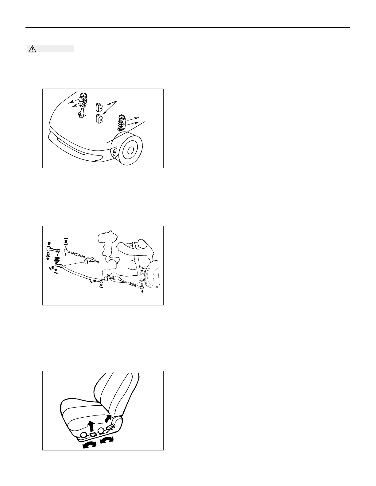
REMOVE FRONT SPRING RESTRAINTS
CAUTION
It is very important that these restraints must be
removed during predelivery-inspection. Failure
to do so could cause ride and handling com
-
plaints.
Spring
restraints
AC305605
With the vehicle correctly positioned on the
sub-frame contact points, and the suspension fully
extended, remove the rubber restraints from the front
springs.
15. STEERING LINKAGE AND SPLIT PINS
M6010600300023
1. Steering linkage retaining nuts and split pins
Check visually and by feel that the steering
linkage retaining nuts are correctly tightened and
the split pins are correctly installed.
2. Tie rods and relay rod
Check that the tie rods and relay rod of the
steering linkage are not bent and that the tie rod
end lock nuts are securely tightened.
3. Steering components
(1) Check that each of the steering components is
tightened.
(2) Check the tie rod end, nuts and split pins for
proper installation.
(3) Check the condition of bellows-type dust
seals.
4. Split pins
Check the front axle nuts and rear wheel spindle
nuts for split pins.
16. UNDER BODY
M6010600400020
Check under body and under body coating for damage.
AC305604
BEFORE ROAD TEST
17. SEAT ADJUSTERS AND SEATBACK LATCHES
M6010700100082
AC305622
Check the operation of the various parts of the seats.
1. Mechanical adjusters of the seats
2. Operation of the latch for tilting the seatbacks
forward and backward.
18. INHIBITOR SWITCH
M6010701100029
On models with an automatic transmission, be sure
the engine starts in both "P" and "N" position, and
does not start in other positions.
19. IDLE CONTROL KNOB
M6010700300020
Verify that the diesel engine revolution increases
when the idle control knob is pulled out.
Page 18
1-12
PRE-DELIVERY INSPECTION
20. INSTRUMENT PANEL CONTROLS
M6010700400083
Check the operation of the following
1. Horn
2. Headlamps
3. Exterior and interior lamps
4. Instrument panel lamps
5. Instrument brightness control
BEFORE ROAD TEST
21. METERS, GAUGES, WARNING LAMPS AND INDICATION LAMPS
M6010700500024
AC305624
1. Check the meters and gauges are functioning
properly.
2. Check each indicator lamp and warning lamp
functions properly.
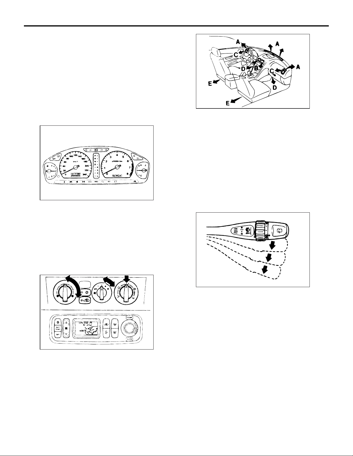
22. AIR CONDITIONER, HEATER AND
DEFROSTER SYSTEM
M6010700600021
Check the systems for proper operation.
AC305626
2. Heater and defroster
(1) After the engine has warmed up, turn on the
heater.
(2) Operate the blower motor switch in all ranges.
(3) Move the control to "Defrost" position.
A: From front and side defroster
B: From centre ventilators
C: From side ventilators
D: From under the instrument panel
E: From under the front seat (some models only)
23. WIPERS AND WASHERS
M6010700700028
AC305625
1. Air conditioner
(1) Operate the air conditioner system.
(2) Operate the air conditioner light.
(3) Operate the control lever in all ranges.
(4) Operate the blower motor switch in all ranges.
AC305627
1. Front wiper and washer
(1) Check operation of the front wipers in all
ranges.
(2) Check the aim of the front washer stream.
(3) Check the wiper blade-stop positions.
(4) Verify that the interval between cycles of
wiping is shifted when timer knob is turned to
any position.
(5) Verify that the front wipers function by
operating the washer switch.
2. Rear wiper and washer
(1) Check the operation of the rear wiper.
(2) Check the aim of the rear washer stream.
(3) Check the wiper blade-stop positions.
Page 19
PRE-DELIVERY INSPECTION
BEFORE ROAD TEST
1-13
24. OPERATION OF SERVICE BRAKES AND PARKING BRAKES
M6010700800274
Depress the brake pedal
with approximately 500
N force
AC305628
1. Service brakes
(1) Check the clearance between the brake pedal
and the floor board when the brake pedal is
depressed.
AB
1. Check the clutch operation in all driving ranges.
2. Check the pedal to floorboard clearance when the
clutch is just disengaged.
AC305631
3. Verify correct clutch pedal free play.
NOTE: For inspection and adjustment of the
clutch pedal, refer to GROUP 2, Periodic Inspec
-
tion and Maintenance.
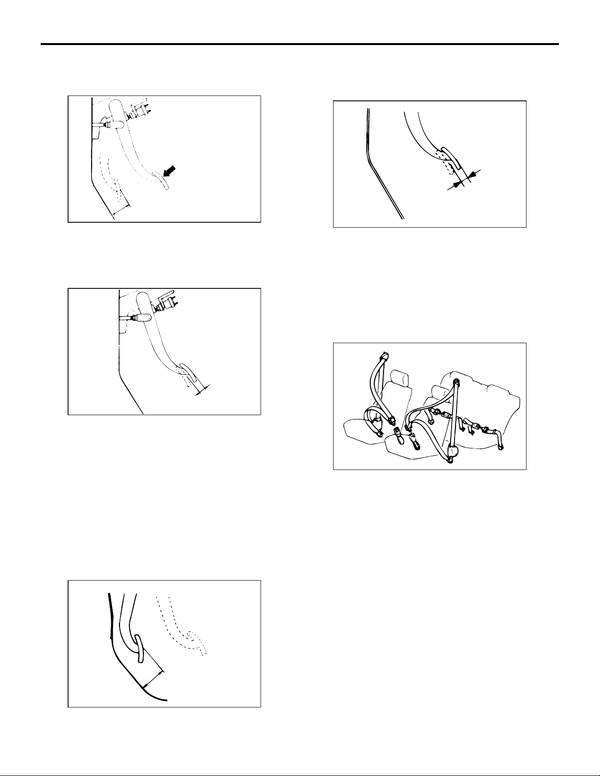
26. OPERATION OF SEAT BELTS,
SHOULDER BELTS AND RETRACTORS
M6010701000022
AC305629
(2) Verify correct brake pedal free play.
NOTE: For inspection and adjustment of the
service brake, refer to GROUP 2, Periodic
Inspection and Maintenance.
2. Parking brake
Check the parking brake drag and lever travel.
NOTE: For inspection and adjustment of the parking brake, refer to GROUP 2, Periodic Inspection
and Maintenance.
25. CLUTCH OPERATION
M6010700900282
AC305632
1. Verify that the seat belt warning lamp operates
properly.
2. Check all seat belts and harnesses to assure that
they connect and hold properly.
3. Lean forward to check that the shoulder
harnesses allow movement.
4. Check the condition of the belts and anchors.
5. Check for proper seat belt retraction.
AC305630
AC
Page 20
1-14
27. ENGINE PERFORMANCE AND EXHAUST GAS
M6010800100023
PRE-DELIVERY INSPECTION
ROAD TEST
ROAD TEST
Button
AC305633
1. Engine performance
Check the engine for proper performance and
accelerator pedal for smooth operation.
2. Exhaust system
(1) Check the exhaust system components for
gas leaks.
(2) Verify that no black smoking is emitted from
the end of the exhaust pipe (diesel-powered
vehicles).
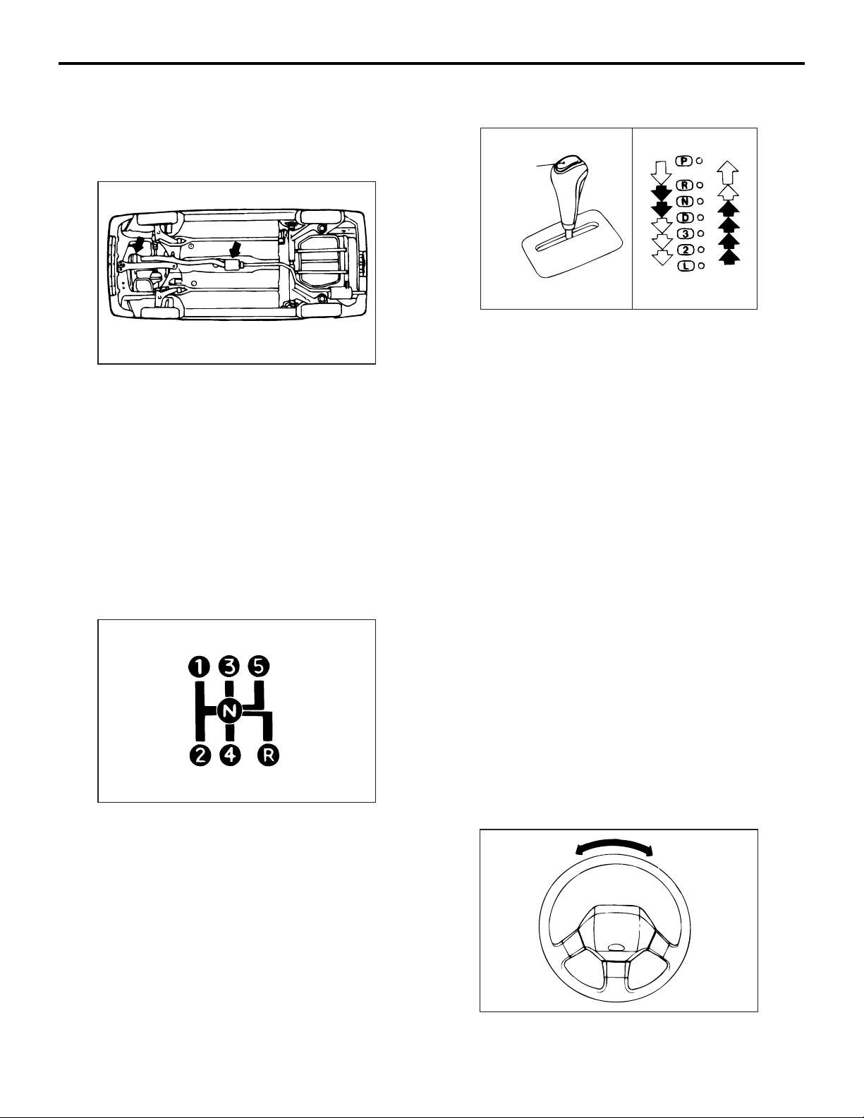
28. TRANSMISSION IN ALL RANGES
M6010800200020
AC305635
AB
2. Automatic transmission
(1) Make sure shift indicator lines up properly in
all ranges.
(2) Depress the accelerator completely to check
that the manual kickdown is operating
correctly.
(3) Stop the vehicle on a steep incline.
Put the automatic transmission in "P" position
and slowly release the service brakes to see if
"P" position lock holds. If it does not hold, the
transmission requires further service.
29. BRAKES
M6010800300027
1. Service Brake
Put the vehicle in gear and apply the brakes while
the vehicle is in motion. Be sure brake operation
is smooth and positive.
2. Parking Brake
(1) Stop the vehicle on a steep incline.
With the service brakes firmly applied, place
the transmission in "N" position, and set the
parking brakes.
(2) Slowly release the service brakes to see if the
parking brakes will hold.
AC305634
1. Manual transmission
Check the transmission in all forward ranges and
in reverse.
30. STEERING CONTROL
M6010800400024
AC305636
1. Check for excessive play or looseness.
2. Check the steering wheel centre.
Page 21
PRE-DELIVERY INSPECTION
AFTER ROAD TEST
1-15
31. VIBRATION AND RATTLES
M6010800500021
1. Locate squeaks, rattles and unusual vibrations.
2. Verify that no noise occurs from the engine,
transmission, axle and body.
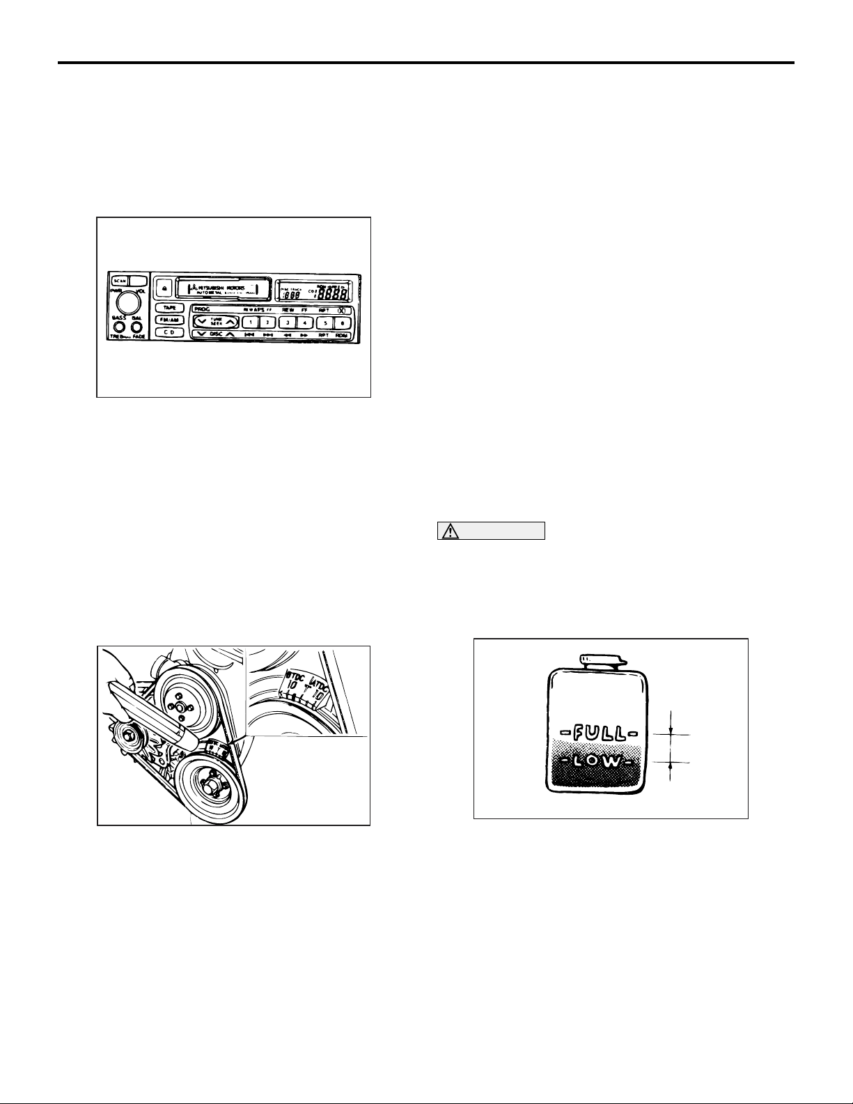
32. ELECTRICAL EQUIPMENT
M6010800600028
AC305637
AFTER ROAD TEST
1. Radio
Tune the radio to a local broadcasting station and
check the following:
(1) Operate the volume, tone, balance and fader
controls, etc.
(2) Pull out the pushbuttons, dial another station
and set each pushbuttons.
(3) Operate the AM/FM switch.
2. Tape player
Insert a cassette tape in the tape player and
check as follows:
(1) Check the operation of the tape feeder and
rewind.
(2) Check the ejection.
(3) Check the operation of volume, tone, balance
and fader controls, etc.
33. IDLE SPEED
M6010900100172
Check the engine idle speed.
NOTE: For specific idle speed adjustment procedure, refer to GROUP 2, Periodic Inspection and
Maintenance.
34. IGNITION TIMING
M6010900200179
AC305641
Check the ignition timing. Except MPI vehicles with
crankshaft-mounted crankshaft angle sensor.
NOTE: For the inspection and adjustment of the ignition timing, refer to GROUP 2, Periodic Inspection
and Maintenance.
35. RADIATOR COOLANT LEVEL
M6010900300154
CAUTION
Do not remove the radiator cap while the cooling
system is under pressure.
When removing the radiator cap, be careful of
steam and boiling water. Add coolant only to the
reserve tank if it is required.
1. Check that the coolant level in the reserve tank is
at or above "LOW" mark at normal engine
operating temperature. And check cooling system
for leaks.
2. Check that the coolant concentration is 30% to
60%.
AC305642
Page 22
1-16
PRE-DELIVERY INSPECTION
AFTER ROAD TEST
36. HOSES, FLUID LINES AND CONNECTIONS LOCATED UNDER HOOD
M6010900400203
CAUTION
Remember that the air conditioner system is
under pressure.
AC305643
1. Check all brake, fuel, power steering and air
conditioner lines and connections; verify proper
routing, check connections for leaks, tighten loose
connector as required.
2. Inspect routing and connections of all vacuum,
and radiator and heater houses.
NOTE: Keep in mind that an oily residue around
an air conditioner connector does not necessarily
indicate a leak. Oil is used to lubricate fittings dur
ing assembly. Be sure lines are not twisted or
kinked.
37. MANUAL TRANSMISSION AND
TRANSFER (4WD) OIL LEVEL
M6010900500211
Transmission oil
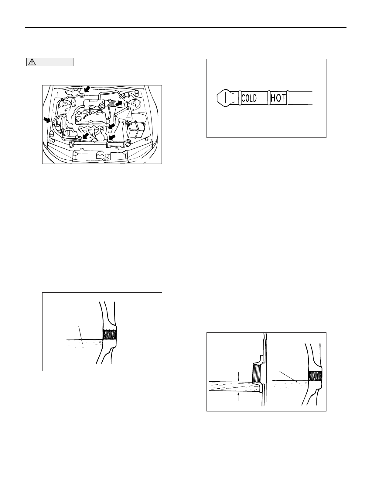
38. AUTOMATIC TRANSMISSION FLUID LEVEL
M6010900600230
AC005861
AD
1. Remove the dipstick and check the fluid level.
2. Fluid level is okay if it is in the specified range as
illustration at normal engine operating
temperature.
3. If the level is below the lower notch, replenish fluid
until the level reaches the upper notch.
NOTE: For the specified automatic transmission
fluid, refer to GROUP 2, Periodic Inspection and
Maintenance.
39. ENGINE, TRANSMISSION, STEERING
GEAR BOX AND DIFFERENTIAL FOR
-
LEAKS
M6010900700055
Check the engine, transmission, steering gear box
and differential for oil leaks.
40. FRONT AND REAR DIFFERENTIAL
OIL LEVELS
M6010900800234
1. Remove the filler plug.
2. Check the oil level. If the oil level is at or slightly
below the filler hole, it is in satisfactory condition.
TYPE 1 TYPE 2
•
AC305644
AB
1. Remove the filler plug.
2. Check the oil level. If the oil level is at or slightly
below the filler hole, it is in satisfactory condition.
3. If the level is low, replenish the transmission and
transfer case with fresh oil by using a lubricator.
NOTE: For the specified oil, refer to GROUP 2,
Periodic Inspection and Maintenance.
Upper
limit
Lower
limit
8 mm
Gear oil
AC305646
AC
Type 1 only: Remove the filler plug, and check the
gear oil level. Check that gear oil level is not 8
mm below the bottom of filler plug hole.
3. If the level is low, replenish the front and/or rear
differential with fresh oil by using a lubricator.
Page 23

PRE-DELIVERY INSPECTION
FINAL STEPS
1-17
NOTE: For the specified oil, refer to GROUP 2,
Periodic Inspection and Maintenance.
41. HOSES, FLUID LINES AND CONNECTIONS LOCATED UNDER VEHICLE
M6010901000145
AC305647
FINAL STEPS
42. HEADLAMP AIMING
M6011000100116
Screen
Level surface
Check condition for headlamp aiming.
NOTE: For headlamp aiming procedures, refer to the
Workshop Manual for that model.
43. EQUIPMENT
Headlamp
AC305648
AB
M6011000200050
1. Check all hoses, fluid lines and connections for
leaks.
2. Check all hoses and fluid lines for proper routing
away from sharp edges and moving components.
Check the installation of the various equipment.
1. Floor mats
2. Spare tyre
3. Jack, jack handle and tool set
44. EXTERIOR AND INTERIOR
M6011000300187
Finally check and clean the exterior and interior.
1. Wash the vehicle to remove all traces of road
grime and other dirt on the vehicle as a result of
new vehicle preparations.
2. Clean exterior and interior glass surface.
3. Remove all protective covers.
4. Remove undercoat overspray, excess window
sealer, and excess weatherstrip adhesive.
5. Verify that the secondary key can not unlock the
glove box and tailgate/boot lid (if so equipped).
6. Remove shipping and inspection stickers.
AC305649
45. OWNER INSTRUCTIONS
M6011000400054
1. Verify that the owner's manual and service
booklet is in the glove box.
2. Place the spare keys in envelope in the glove box
before delivery.
Page 24

NOTES
Page 25

GROUP 2
PERIODIC
INSPECTION AND
MAINTENANCE
CONTENTS
2-1
PERIODIC INSPECTION AND
MAINTENANCE SCHEDULE . . . . . . 2-3
OPERATIONS INSIDE THE ENGINE
COMPARTMENT . . . . . . . . . . . . . . . . 2-7
A1. CHECK V-BELT FOR CRACKS, FRAYING,
WEAR, AND ADJUST ITS TENSION . . . . . 2-7
A2. CHECK VACUUM PUMP OIL HOSE FOR
DAMAGE. . . . . . . . . . . . . . . . . . . . . . . . . . . 2-9
A3. CHECK INTAKE AIR HOSE AND
TURBOCHARGER OIL HOSE FOR DAMAGE 2-9
A4. REPLACE ENGINE TIMING BELT
<EXCEPT VEHICLES WITH TIMING CHAIN> 2-9
A5. CHECK OPERATION OF CRANKCASE
EMISSION CONTROL SYSTEM . . . . . . . . 2-10
A6. REPLACE SPARK PLUGS. . . . . . . . . . 2-11
A7. CHECK VALVE CLEARANCE (EXCEPT
VEHICLES AUTO-LASH ADJUSTER) . . . . 2-11
A8. CHECK RADIATOR HOSES FOR DAMAGE
AND PROPER CONNECTION . . . . . . . . . . 2-15
A9. CHECK ENGINE COOLANT LEVEL IN
RESERVOIR. . . . . . . . . . . . . . . . . . . . . . . . 2-15
A10. CHANGE ENGINE COOLANT . . . . . . 2-15
A11. CHECK AIR CLEANER ELEMENT FOR
CLOGGING AND DAMAGE . . . . . . . . . . . . 2-17
A12. REPLACE AIR CLEANER ELEMENT 2-17
A13. CHECK FLUID LEVEL IN BRAKE
RESERVOIR. . . . . . . . . . . . . . . . . . . . . . . . 2-18
A14. CHECK FLUID LEVEL IN CLUTCH
RESERVOIR (FOR HYDRAULIC TYPE
CLUTCH ONLY) . . . . . . . . . . . . . . . . . . . . . 2-18
A15. CHANGE BRAKE FLUID . . . . . . . . . . 2-18
A16. CHECK BATTERY ELECTROLYTE
LEVEL . . . . . . . . . . . . . . . . . . . . . . . . . . . . . 2-19
A17. CHECK INJECTION NOZZLE [IF DARK
SMOKE IS EXHAUSTED OR ENGINE POWER
IS LOW] <4M40> . . . . . . . . . . . . . . . . . . . . . 2-20
A18. REPLACE FUEL FILTER . . . . . . . . . . 2-21
OPERATIONS UNDER THE VEHICLE 2-24
B1. CHECK SUSPENSION SYSTEM FOR
DAMAGE AND LOOSENESS . . . . . . . . . . . 2-24
B2. CHECK SUSPENSION ARM BALL JOINTS
FOR PLAY, AND DUST COVERS FOR
DAMAGE . . . . . . . . . . . . . . . . . . . . . . . . . . . 2-25
B3. LUBRICATE PROPELLER SHAFT WITH
GREASE FITTING. . . . . . . . . . . . . . . . . . . . 2-25
B4. CHECK DRIVESHAFT BOOTS FOR
DAMAGE . . . . . . . . . . . . . . . . . . . . . . . . . . . 2-25
B5. CHECK STEERING LINKAGE FOR
DAMAGE AND LOOSE CONNECTIONS
(Including seals and boots). . . . . . . . . . . . . 2-25
B6. CHECK GEAR OIL LEVEL IN MANUAL
TRANSMISSION . . . . . . . . . . . . . . . . . . . . . 2-26
B7. CHECK GEAR OIL LEVEL IN TRANSFER
CASE (4WD) . . . . . . . . . . . . . . . . . . . . . . . . 2-26
B8. CHANGE GEAR OIL IN MANUAL
TRANSMISSION . . . . . . . . . . . . . . . . . . . . . 2-26
B9. CHANGE GEAR OIL IN TRANSFER
CASE (4WD) . . . . . . . . . . . . . . . . . . . . . . . . 2-27
B10. CHECK GEAR OIL LEVEL IN FRONT
AND REAR DIFFERENTIAL . . . . . . . . . . . . 2-27
B11. CHANGE GEAR OIL IN FRONT AND
REAR DIFFERENTIAL . . . . . . . . . . . . . . . . 2-27
B12. CHECK EXHAUST PIPE CONNECTIONS
FOR GAS LEAKAGE, AND CHECK PIPE
INSTALLATION . . . . . . . . . . . . . . . . . . . . . . 2-28
Continued on next page
Page 26

2-2
OPERATIONS INSIDE THE VEHICLE 2-28
C1. CHECK BRAKE PEDAL AND CLUTCH
PEDAL FOR FREE PLAY . . . . . . . . . . . . . . 2-28
C2. CHECK PARKING BRAKE LEVER STROKE
AND PLAY . . . . . . . . . . . . . . . . . . . . . . . . . 2-30
C3. REPLACE AIR PURIFIER FILTER. . . . 2-30
OPERATIONS OUTSIDE THE VEHICLE 2-31
D1. CHECK WHEEL ALIGNMENT . . . . . . . 2-31
D2. CHECK FRONT AND REAR WHEEL
BEARINGS FOR PLAY. . . . . . . . . . . . . . . . 2-33
D3. CHECK BRAKE HOSES AND PIPES FOR
LEAKAGE . . . . . . . . . . . . . . . . . . . . . . . . . . 2-34
D4. CHECK BRAKE PADS AND DISCS FOR
WEAR . . . . . . . . . . . . . . . . . . . . . . . . . . . . . 2-34
D5. CHECK BRAKE SHOE LININGS AND
DISCS FOR WEAR. . . . . . . . . . . . . . . . . . . 2-35
D6. CHECK FUEL HOSES AND PIPES FOR
LEAKAGE OR DETERIORATION . . . . . . . 2-36
OPERATIONS AFTER ENGINE IS
WARMED UP . . . . . . . . . . . . . . . . . . . 2-37
E1. CHECK FLUID LEVEL IN AUTOMATIC
TRANSMISSION . . . . . . . . . . . . . . . . . . . . . 2-37
E2. CHANGE AUTOMATIC TRANSMISSION
FLUID . . . . . . . . . . . . . . . . . . . . . . . . . . . . . 2-37
E3. CHANGE ENGINE OIL . . . . . . . . . . . . . 2-39
E4. REPLACE ENGINE OIL FILTER . . . . . 2-40
E5. CHECK ENGINE IDLING SPEED AND
CO CONCENTRATION . . . . . . . . . . . . . . . . 2-41
E6. CHECK EXHAUST GAS RECIRCULATION
(EGR) SYSTEM. . . . . . . . . . . . . . . . . . . . . . 2-44
OTHERS . . . . . . . . . . . . . . . . . . . . . . . 2-48
F1. CHECK BODY CONDITION FOR
DAMAGE . . . . . . . . . . . . . . . . . . . . . . . . . . . 2-48
F2. CHECK THE COMMON RAIL ENGINE
(small injection quantity learning) . . . . . . . . 2-48
F3. ROAD TEST . . . . . . . . . . . . . . . . . . . . . 2-48
Page 27

PERIODIC INSPECTION AND MAINTENANCE
PERIODIC INSPECTION AND MAINTENANCE SCHEDULE
2-3
PERIODIC INSPECTION AND MAINTENANCE SCHEDULE
M6020100100702
For items which indicate both distance and time (in months), the inspection should be made at whichever
(distance or time) comes first.
Maintenance item Maintenance
operation
OPERATIONS INSIDE THE ENGINE COMPARTMENT
A1 Check V-belt for cracks, fraying, wear, and
adjust its tension
A2 Check vacuum pump oil hose for damage
(diesel-powered vehicles)
A3 Check intake air hose and turbocharger oil
hose for damage (vehicles with turbocharger)
A4 Replace engine timing belt (except vehicles
with timing chain)
A5 Check operation of crankcase emission
control system
A6 Replace spark plugs 3 earth
electrodes
semi-surfa
ce
discharge
type
Iridium-tipp
ed type
A7 Check valve
clearance (except
vehicles with
auto-lash adjuster)
A8 Check radiator hoses for damage and proper
connection
A9 Check engine coolant level in reservoir Inspection First 1,000 km, thereafter every
A10 Change engine coolant Change Every 40,000 km or every 2 years
Except vehicles with
6G75 engine
Vehicles with 6G75
(intake side) engine
Leaded
petrol-pow
ered
vehicles
Unleaded
petrol-pow
ered
vehicles
Unleaded
petrol-pow
ered
vehicles
Inspection First 1,000 km, thereafter every
Inspection Every 20,000 km or every 12 months
Inspection Every 40,000 km or every 2years (over
Replace Every 100,000 km
Inspection Every 40,000 km or every 2 years
Replace Every 40,000 km
Replace Every 100,000 km
Replace Every 100,000 km
Inspection First 1000 km, thereafter every 20,000
Inspection Every 40,000 km or every 2 years (If
Inspection Every 40,000 km or every 2 years
Maintenance interval
20,000 km or every 12 months
100,000 km, every 20,000 km for
turbocharger oil hose)
km or every 12 months
valve noise increases, check valve
clearance additionally to the
scheduled service.)
20,000 km or every 12 months
A11 Check air cleaner element for clogging and
damage
Inspection Norma
l usage
Severe
usage
Every 20,000 km or every 12
months
Every 10,000 km or every 6
months
Page 28

2-4
PERIODIC INSPECTION AND MAINTENANCE
PERIODIC INSPECTION AND MAINTENANCE SCHEDULE
Maintenance item Maintenance
operation
A12 Replace air cleaner element Replace Norma
A13 Check fluid level in brake reservoir Inspection First 1,000 km, thereafter every
A14 Check fluid level in clutch reservoir (for
hydraulic type clutch only)
A15 Change brake fluid Change Every 40,000 km or every 2 years
A16 Check battery electrolyte level Inspection First 1,000 km, thereafter every
A17 Check injection nozzle [If dark smoke is
exhausted or engine power is low]
A18 Replace fuel filter Petrol-powered
vehicles
Diesel-powered
vehicles
OPERATIONS UNDER THE VEHICLE
B1 Check suspension system for damage and
looseness
B2 Check suspension arm ball joints for play, and
dust covers for damage
B3 Lubricate propeller shaft with grease fitting Lubrication Every 20,000 km or every 12 months
B4 Check driveshaft boots for damage Inspection Norma
Inspection First 1,000 km
Inspection Every 50,000 km or every 2.5 years
Replace Every 60,000 km or every 3 years
Replace Every 20,000 km or every 12 months
Inspection First 1,000 km, thereafter every
Inspection Every 20,000 km or every 12 months
Maintenance interval
Every 40,000 km or every 2
l usage
Severe
usage
10,000 km or every 6 months
10,000 km or every 6 months
20,000 km or every 12 months
l usage
years
More frequently
Every 20,000 km or every 12
months
Severe
usage
B5 Check steering linkage for damage and loose
connections (including seals and boots)
B6 Check gear oil level in manual transmission Inspection Every 20,000 km or every 12 months
B7 Check gear oil level in transfer case (4WD) Inspection Every 20,000 km or every 12 months
B8 Change gear oil in manual transmission Change Norma
B9 Change gear oil in transfer case (4WD) Change Norma
B10 Check gear oil level in front and rear
differential
Inspection Every 20,000 km or every 12 months
l usage
Severe
usage
l usage
Severe
usage
Inspection Every 20,000 km or every 12 months
First 1,000 km, thereafter
every 10,000 km or every 6
months
Every 100,000 km or every 5
years
Every 40,000 km or every 2
years
Every 100,000 km or every 5
years
Every 40,000 km or every 2
years
Page 29

PERIODIC INSPECTION AND MAINTENANCE
PERIODIC INSPECTION AND MAINTENANCE SCHEDULE
2-5
Maintenance item Maintenance
operation
B11 Change gear oil in front and rear differential Change Norma
B12 Check exhaust pipe connections for gas
leakage, and check pipe installation
OPERATIONS INSIDE THE VEHICLE
C1 Check brake pedal and clutch pedal for free
play
C2 Check parking brake lever stroke and play Inspection First 1,000 km, thereafter every
C3 Replace air purifier filter Replace Every 15,000 km or every 12 months
OPERATIONS OUTSIDE THE VEHICLE
D1 Check wheel alignment Inspection Every 20,000 km or every 12 months
D2 Check front and rear wheel bearings for play Inspection Every 60,000 km or every 3 years
D3 Check brake hoses and pipes for leakage Inspection Every 20,000 km or every 12 months
D4 Check brake pads and discs for wear Inspection Norma
Inspection Every 20,000 km or every 12 months
Inspection Every 10,000 km or every 6 months
Maintenance interval
Every 80,000 km or every 4
l usage
Severe
usage
20,000 km or every 12 months
l usage
years
Every 40,000 km or every 2
years
Every 20,000 km or every 12
months
Severe
usage
D5 Check brake shoe linings and discs for wear Inspection Norma
l usage
Severe
usage
D6 Check fuel hoses and pipes for leakage or
deterioration
OPERATIONS AFTER ENGINE IS WARMED UP
E1 Check fluid level in automatic transmission Inspection Every 20,000 km or every 12 months
E2 Change automatic transmission fluid Change Severe
E3 Change engine oil
<6G7>
Change engine oil
<4M40>
Change engine oil
<4M41>
ACEA classification
"For service A1/B1,
A3/B3, A3/B4 or A5/B5"
API classification "For
service SG" or higher
ACEA classification
"For service A1/B1,
A3/B3, A3/B4 or A5/B5"
API classification "For
service CD" or higher
ACEA classification
"For service A1/B1,
A3/B3, A3/B4 or A5/B5"
API classification "For
service CD" or higher
Inspection Every 40,000 km or every 2 years
usage
Change Norma
l usage
Severe
usage
Change Norma
l usage
Severe
usage
Change Norma
l usage
Severe
usage
Every 5,000 km or every 6
months
Every 40,000 km or every 2
years
Every 10,000 km or every 6
months
Every 40,000 km or every 2
years
Every 15,000 km or every 12
months
Every 5,000 km
Every 5,000 km or every 6
months
Every 3,000 km
Every 15,000 km or every 12
months
Every 7,500 km
Page 30

2-6
PERIODIC INSPECTION AND MAINTENANCE
PERIODIC INSPECTION AND MAINTENANCE SCHEDULE
Maintenance item Maintenance
operation
E4 Replace engine oil filter <6G7> Replace Norma
Replace engine oil filter <4M40> Replace Norma
Replace engine oil filter <4M41> Replace Norma
E5 Check engine idling speed and CO
concentration (petrol-powered vehicles)
Check engine idling speed (diesel-powered
vehicles)
E6 Check exhaust gas recirculation (EGR)
system
Inspection First 1,000 km, thereafter every
Inspection First 1,000 km, thereafter every
Inspection Every 20,000 km or every 12 months
Maintenance interval
l usage
Severe
usage
l usage
Severe
usage
l usage
Severe
usage
20,000 km or every 12 months
20,000 km or every 12 months
Every 15,000 km or every 12
months
Every 5,000 km
Every 10,000 km or every 12
months
Every 6,000 km
Every 15,000 km or every 12
months
Every 7,500 km
OTHERS
F1 Check body condition for damage Inspection Every year
F2 Check the common rail engine (small injection
quantity learning)
F3 Road test Inspection First 1,000 km, thereafter every
NOTE: "Severe usage" specifications apply to only vehicles used under severe operating conditions.
Severe operating conditions include the following cases:
.
1. Driving in a dusty area or in an area in which the vehicle is likely to be exposed to salty air or brine.
2. Driving on rough roads, on submerged roads, or hilly areas.
3. Driving in cold zones.
4. Engine idling for a long time or short-distance travel during cold weather.
5. Frequent, sudden application of brakes.
6. Towing of a trailer.
7. Use as a taxi or as a rent-a-car.
8. More than 50% of operation time in heavy city traffic in hot temperatures of 32°C or higher.
9. More than 50% of operation time at speeds of 120 km/h or higher in hot temperatures of 30°C or higher.
Inspection Every 20,000 km or every 12 months
20,000 km or every 12 months
10. Operation under excessive load.
Page 31

PERIODIC INSPECTION AND MAINTENANCE
OPERATIONS INSIDE THE ENGINE COMPARTMENT
OPERATIONS INSIDE THE ENGINE COMPARTMENT
2-7
A1. CHECK V-BELT FOR CRACKS, FRAYING, WEAR, AND ADJUST ITS TENSION
M6020200100561
V-BELT CONDITION
Check the whole rounds of the V-belt for cracks, fraying and wear.
V-BELT TENSION
ALTERNATOR DRIVE BELT TENSION
CHECK <6G7>
CAUTION
Check the alternator drive belt tension after turning the crankshaft clockwise one turn or more.
Alternator drive belt
auto-tensioner
<4M41>
Item When
checked
Vibration
frequency
Hz
Tension N 245 − 441 294 − 392 392 − 588
Deflection
mm
(Reference)
150 − 201 164 − 190 190 − 232
9.1 − 12.7 9.8 − 11.7 7.2 − 9.8
When
adjusted
When
replaced
<WHEN THE VIBRATION FREQUENCY IS
MEASURED {SPECIAL TOOL (MB992080)
IS USED}: RECOMMENDATION>
NOTE: The vibration frequency measuring method is
recommended for check and adjustment of the drive
belt tension.
Belt tension meter set (MB992080)
MB992081
A
1. Make sure that the indicator mark is within the
area marked with A in the illustration.
2. If the mark is out of the area, replace the drive
belt.
NOTE: The alternator drive belt tension check is
not necessary as alternator drive belt auto-ten
sioner is adopted.
Indicator mark
AC511210
AB
ALTERNATOR DRIVE BELT TENSION
CHECK AND ADJUSTMENT <4M4>
Check the drive belt tension in the following procedure.
STANDARD VALUE:
<4M40>
Item When
checked
Vibration
frequency
Hz
Tension N 294 − 490 343 − 441 490 − 686
Deflection
mm
(Reference)
103 − 132 111 − 125 132 − 156
8.0 − 11.0 9.0 − 11.0 8.0 − 9.0
When
adjusted
When
replaced
MB992082
AC507219
1. Connect the Special tool microphone assembly
(MB992082) to the Special tool belt tension meter
-
(MB992081) of the Special tool belt tension meter
set (MB992080).
2. Press the "POWER" button to turn on the power
supply.
3. Press number key 1. Check to ensure that "No.
01" appears on the upper left of the display and
that the following numeric values are displayed for
individual items (M, W, and S):
M 000.9 g/m
W 010.0 mm/R
S 0100 mm
If numeric values have not been entered (new
tool), set them according to the belt specifications
as shown below. Once you set them, you do not
have to set them again. The settings remain
undeleted even after battery replacement.
AB
Page 32

2-8
PERIODIC INSPECTION AND MAINTENANCE
OPERATIONS INSIDE THE ENGINE COMPARTMENT
NOTE: This operation is to temporarily set the
preset data such as the belt specifications,
because if the measurement is taken without input
of the belt specifications, conversion to tension
value (N) cannot be made, resulting in judgement
of error.
<Setting procedure>
(1) Press down the "MASS" button till the belt
mass select display appears.
(2) Press the "UP" or "DOWN" button to select "01
1.5GT 0.9" and press the "MEASURE" button
to decide it.
Check to ensure that "M 000.9 g/m" is
displayed.
(3) Press the "WIDTH" button to change to the
belt width input display.
(4) Press number keys 0, 1, 0, and 0 sequentially,
and press the "SELECT" button to apply them.
Check to ensure that "W 010.0 mm/R"
appears on the display.
(5) Press the "SPAN" button to change to the
span length input display.
(6) Press number keys 0, 1, 0, and 0 sequentially,
and press the "SELECT" button to apply them.
Check to ensure that "S 0100 mm" appears on
the display.
4. Press "Hz" button twice to change the display to
the frequency display (Hz).
CAUTION
• The temperature of the surface of the belt
should be as close as possible to normal tem
perature.
• Do not let any contaminants such as water or
oil get onto the microphone.
• If strong gusts of wind blow against the
microphone or if there is loud sources of
noise nearby, the values measured by the
microphone may not correspond to actual
values.
• If the microphone is touching the belt while
the measurement is being made, the values
measured by the microphone may not corre
spond to actual values.
• Do not take the measurement while the vehicle's engine is running.
MB992080
(Microphone)
15˚
10 – 15 mm
Alternator
pulley
15˚
Gentry tap
with your
finger
Water pump
pulley
AC600283
AB
5. Hold the microphone to the middle of the drive
belt between the pulleys (at the place indicated by
the arrow), about 10
− 15 mm away from the rear
surface of the belt and so that it is perpendicular
to the belt (within an angle of
± 15 ° ).
6. Press the "MEASURE" button.
7. Gently tap the middle of the belt between the
pulleys (the place indicated by the arrow) with
your finger as shown in the illustration, and check
that the vibration frequency of the belt is within the
standard value.
NOTE: To take the measurement repeatedly, fillip
the belt again.
8. After the completion of the measurement, press
and hold the "POWER" button to turn off the
power supply.
-
-
Page 33

PERIODIC INSPECTION AND MAINTENANCE
OPERATIONS INSIDE THE ENGINE COMPARTMENT
2-9
<WHEN USING THE TENSION GAUGE>
Water pump
Tension
gauge
Alternator
pulley
pulley
AC600285
AB
Use a belt tension gauge to check that the belt tension is within the standard value.
<BELT DEFLECTION CHECK>
Approximately
100N
Deflection
Water pump
pulley
Crankshaft
pulley
4. Tighten the nut for alternator pivot bolt.
Tightening torque: 47 ± 9 N⋅ m
5. Tighten the alternator fixing nut.
Tightening torque: 24 ± 4 N⋅ m
6. Tighten the adjusting bolt.
Tightening torque: 5.0 ± 1.0 N⋅ m
A2. CHECK VACUUM PUMP OIL HOSE FOR DAMAGE
M6020200400108
Hose
AC502483
1. Inspect the surface of hose for evidence of heat
and mechanical damage.
AE
Alternator pulley
AK500540AB
Apply approximately 100 N of force to the middle of
the drive belt between the pulleys (at the place indi
cated by the arrow) and check that the amount of
deflection is within the standard value.
When the belt tension is adjusted by measuring the
deflection, adjust it with a tool for vibration frequency
measurement or tension measurement afterward.
If not within the standard value, adjust the belt tension by the following procedure.
Adjusting
bolt
Alternator
fixing nut
Alternator pivot bolt
AC702321
AB
1. Loosen the nut of the alternator pivot bolt.
2. Loosen the alternator fixing nut.
3. Use the adjusting bolt to adjust the belt tension
and belt deflection to the standard values.
A3. CHECK INTAKE AIR HOSE AND TURBOCHARGER OIL HOSE FOR DAMAGE
M6020200500235
Turbocharger
AC305652
AB
1. Inspect the intake air hoses for cracks or damage.
2. Inspect the turbocharger oil hoses for cracks or
damage.
A4. REPLACE ENGINE TIMING BELT <EXCEPT VEHICLES WITH TIMING CHAIN>
M6020200600306
For information concerning the replacement procedures, refer to the Workshop Manual.
Page 34

2-10
PERIODIC INSPECTION AND MAINTENANCE
OPERATIONS INSIDE THE ENGINE COMPARTMENT
A5. CHECK OPERATION OF CRANKCASE EMISSION CONTROL SYSTEM
M6020200700347
BREATHER HOSE
Breather hose
AC610025
AB
1. Inspect the breather hose for cracks or damage.
2. Clean the inside of the breather hose if necessary.
3. Inspect the ventilation filter for clogging.
VENTILATION HOSE
1. Check entire circumference and length of hoses
using a mirror as required.
2. Check all clamps for tightness and the connections for leakage.
3. Hoses should be replaced immediately if there is
any evidence of deterioration or damage.
POSITIVE CRANKCASE VENTILATION SYSTEM CHECK
Ventilation hose
1. Remove the ventilation hose from the PCV
(Positive crankcase ventilation) valve.
2. Remove the PCV valve from the rocker cover.
3. Reinstall the PCV valve at the ventilation hose.
4. Start the engine and run at idle.
<6G72>
PCV valve
AC305653
<6G75>
PCV valve
AC609736
AD
AC
5. Place finger at the opening of the PCV valve and
check that vacuum of the intake manifold is felt.
NOTE: At this moment, the plunger in the PCV
valve moves back and forth.
6. If vacuum is not felt, clean the PCV valve or
replace it.
7. Apply a small amount of new engine oil to the
O-ring on the PCV valve, and tighten to the
specified torque. <6G75>
Tightening torque: 2.5 ± 0.4 N⋅ m
PCV valve
AC610047
AB
Page 35

PERIODIC INSPECTION AND MAINTENANCE
OPERATIONS INSIDE THE ENGINE COMPARTMENT
2-11
PCV VALVE CHECK
<6G72>
<6G75>
PCV valve
PCV valve
AC305654
AC609737
AD
AC
5. Move the rocker arms on the No. 1 and No. 4
cylinders up and down by hand to determine
which cylinder has its piston at the top dead
centre on the compression stroke. If rocker arms
have a valve lash, the piston in the cylinder
corresponding to these rocker arms is at the top
dead centre on the compression stroke.
Right bank
No. 1 No. 3 No. 5
No. 2 No. 4 No. 6
Exhaust side
Intaake side
1. Insert a thin rod into the PCV valve from the side
shown in the illustration (rocker cover installation
side), and move the rod back and forth to check
that the plunger moves.
2. If the plunger does not move, there is clogging in
the PCV valve. In this case, clean or replace the
PCV valve.
A6. REPLACE SPARK PLUGS
M6020200800281
After removing old spark plugs, install new ones and
tighten them at the specified torque.
A7. CHECK VALVE CLEARANCE (EXCEPT VEHICLES AUTO-LASH ADJUSTER)
M6020202400137
VALVE CLEARANCE (Intake side) CHECK AND ADJUSTMENT <6G75>
NOTE: The valve clearance check and adjustment
should be done when the engine is cold.
1. Turn the ignition switch to the "LOCK" (OFF)
position.
2. Remove all ignition coils.
3. Remove the rocker cover.
4. Turn the crankshaft clockwise until the notch on
the pulley is lined up with the "T" mark on the
timing indicator.
Left bank
Exhaust side
AK404086
AE
6. Valve clearance inspection and adjustment can be
performed on rocker arms indicated by white
arrow mark when the No. 1 cylinder piston is at
the top dead centre on the compression stroke,
and on rocker arms indicated by black arrow mark
when the No. 4 cylinder piston is at the top dead
centre on the compression stroke.
7. Measure the valve clearance.
If the valve clearance is not as specified, loosen
the rocker arm lock nut and adjust the clearance
using a thickness gauge while turning the
adjusting screw.
Standard value (cold engine):
Intake valve: 0.10 mm
NOTE: Valve clearance check and adjustment is
unnecessary for exhaust side due to auto lash
adjuster installed.
8. Turn the crankshaft through 360 degree angle to
line up the notch on the crankshaft pulley with the
"T" mark on the timing indicator.
9. Repeat steps 7 and 8 on other valves for
clearance adjustment.
10.Install the rocker cover.
11.Install the ignition coils.
Page 36

2-12
PERIODIC INSPECTION AND MAINTENANCE
OPERATIONS INSIDE THE ENGINE COMPARTMENT
VALVE CLEARANCE CHECK AND ADJUSTMENT <4M40>
NOTE: Perform the valve clearance check and
adjustment at the engine cold state.
1. Remove the rocker cover.
2. Remove the glow plug plate and all of the glow
plugs from the cylinder head.
CAUTION
Never turn the crankshaft anticlockwise (the
opposite direction) as the tensioner, which adjust
the timing chain tension at the timing gear, may
be damaged. If so, remove and reinstall the ten
sioner.
"0"
-
Intake
No. 1
Intake
No. 2
Exhaust
No. 1
Intake
No. 3
Exhaust
No. 2
Intake
No. 4
Exhaust
No. 3
Exhaust
No. 4
AK603846AB
4. Check the valve clearances at the places by
arrows in the illustration by the following
procedure.
White arrow: When No. 1 cylinder is at compression
top dead centre position
Black arrow: When No. 4 cylinder is at compression
top dead centre position
Crankshaft pulley
AK601576AB
3. Align the notch of the crankshaft pulley with the
"0" timing mark to set the No. 1 or No. 4 cylinder
to the compression top dead centre position.
Dent
AK601577AB
NOTE: If the dent on the camshaft is pointing directly
upwards, the No. 1 cylinder will be at the compres
sion top dead centre position. If the crankshaft is
then turned once, the No. 4 cylinder will then be at
the compression top dead centre position.
Valve
clearance
AK603982
AB
(1) Use a thickness gauge to measure the valve
clearance. If deviated from standard value,
make a note for the valve clearance.
Standard valve (Cold engine):
Intake side 0.15 − 0.25 mm
Exhaust side 0.25 − 0.35 mm
NOTE: There should be certain amount of
resistance against the thickness gauge when
taking the measurements. If the thickness
gauge is moving too smoothly, a correct meas
urement cannot be obtained.
(2) Use the measured values as a reference for
selecting adjustment shims which will bring the
incorrect valve clearance to the standard
value.
A: thickness of newly installed shim
B: thickness of removed shim
C: measured valve clearance
Equation
Intake valve: A = B + (C − 0.2) mm
Exhaust valve: A = B + (C − 0.3) mm
NOTE: The thicknesses of the adjustment
shims are between 2,250
−
3,150 mm (37types
which increase in thickness by 0.025 mm)
-
Page 37

PERIODIC INSPECTION AND MAINTENANCE
OPERATIONS INSIDE THE ENGINE COMPARTMENT
2-13
Identification
size mark
AK603848
AB
NOTE: Size identification mark: "2775" = 2.775
mm thickness
(3) Remove the camshaft and install the shim
which was selected in step (2).
(4) Re-measure the valve clearances and check
that they are all at the standard value.
5. Turn the crankshaft once to align the notch of the
crankshaft pulley with the timing mark "0".
6. Check and adjust the other valve clearances
according to the step 4.
2. Use the special tool fuel injection pipe wrench
(MB992188) to remove the fuel injection pipe.
3. Remove the rocker cover.
CAUTION
The crankshaft should always be turned in a
clockwise direction.
Timing marks
Camshaft sprocket
Timing marks
VALVE CLEARANCE CHECK AND ADJUSTMENT <4M41>
NOTE: The valve clearance check and adjustment
should be done when the engine is cold.
1. Remove the EGR pipe.
CAUTION
Leaked fuel on parts causes a decrease in function and burning. Therefore, place waste to
absorb leaked fuel.
MB992188
AC609910
AB
Crankshaft pulley
AC610704
AB
4. Align the camshaft sprocket timing marks and set
the No. 1 cylinder at top dead centre.
Exhaust valve side
Intake valve side
AK500544AB
5. Measure the valve clearance.
If the valve clearance is not as specified, loosen
the rocker arm lock nut and adjust the clearance
using a thickness gauge between the camshaft
and the roller while turning the adjusting screw.
Standard value (cold engine):
Intake valve: 0.10 mm
Exhaust valve: 0.15 mm
MB992188
AK600672
AB
Page 38

2-14
PERIODIC INSPECTION AND MAINTENANCE
OPERATIONS INSIDE THE ENGINE COMPARTMENT
CAUTION
Pay special attention that the tightening torque is
not beyond this value. If the tightening torque is
beyond the value, the value stem would possibly
bend.
MB992188
MB992046
Thickness
gauge
AK500542
AB
6. While holding the adjusting screw with a
screwdriver to prevent it from turning, tighten the
lock nut to the specified torque using a valve
adjusting socket. (MB992046)
Tightening torque: 9.8 ± 1 N⋅ m
7. Turn the crankshaft 360° clockwise to bring No. 4
cylinder to the top dead centre position.
Exhaust valve side
Intake valve side
AK500544AC
8. Measure the valve clearances at the places
indicated by arrows in the illustration. If the
clearance is not within the standard value, repeat
steps 5 and 6 above.
9. Install the rocker cover.
AC609910
MB992188
AK600672
AB
AB
10.Use the special tool fuel injection pipe wrench
(MB992188) to tighten the fuel injection pipe to
the specified torque.
Tightening torque: 35 ± 5 N⋅ m
CAUTION
• The reinstallation histories of the removed
injection pipe are up to five times. To count
how many times the injection pipe is rein
stalled, record the number of the reinstallation histories on the service booklet by
adding this latest number of the histories,
which is usually "1", to the previous one. Use
a new injection pipe when the total reinstalla
tion history numbers reach five times, or
when the injector or common rail is replaced.
In this case, record "a new injection pipe, the
number of the reinstallation histories is zero"
on the service booklet.
• When the injection pipe is reinstalled, confirm
there is no foreign material on the seal sur
face or in the pipe and then install it not to
deviate from the axis, fitting the seal surface.
11.Install the EGR pipe.
12.After the ignition switch is in "LOCK" (OFF)
position, connect the M.U.T.-III to the diagnosis
connector.
13.Start the engine, and let it run at idle.
14.Select SPECIAL FUNCTION from the function
menu.
15.Select FUEL LEAKAGE CHECK from SPECIAL
FUNCTION menu to execute the test.
-
Page 39

PERIODIC INSPECTION AND MAINTENANCE
OPERATIONS INSIDE THE ENGINE COMPARTMENT
2-15
NOTE: During the test, the engine speed and the fuel
pressure is 2, 000 r/min and 180MPa for 20 seconds
respectively.
16.Confirm there is no fuel leak from the joint for the
injection pipe.
A8. CHECK RADIATOR HOSES FOR DAMAGE AND PROPER CONNECTION
M6020200900545
<6G7>
AC608822
<4M4>
AB
A10. CHANGE ENGINE COOLANT
M6020201100683
1. Stop the engine after it is fully warmed up.
2. Add detergent to the engine coolant in order to
flush the cooling system, and start the engine.
AC305655
3. Loosen the drain plug, remove the radiator can
and drain the coolant.
4. Feed fresh water into the cooling system through
the filler port of the radiator in order to wash the
cooling system, and then tighten the drain plug.
5. Drain the coolant from the radiator condenser
tank.
6. Install the radiator condenser tank.
AC608825
AB
1. Check entire circumference and length of hoses,
using a mirror as required.
2. Check that hoses installed in grommets pass
through the centre of the grommets.
3. Check all clamps for tightness and connections
for leakage.
A9. CHECK ENGINE COOLANT LEVEL IN RESERVOIR
M6020201000545
CAUTION
Do not use alcohol or methanol anti-freeze or any
engine coolants mixed with alcohol or methanol
anti-freeze. The use of an improper anti-freeze
can cause the corrosion of the aluminium com
-
ponents.
AC305656
7. Depending upon conditions of operation,
determine the amount of long life coolant,
antifreeze or antirust to be added to the coolant.
Recommended antifreeze: DIA QUEEN
SUPER LONG LIFE COOLANT or equivalent
Condenser tank
AC608829
AB
Check that the coolant level is between the "FULL"
and "LOW" lines when the engine is at the normal
operating temperature.
8. Fill the cooling system with soft water through the
filler port, and add long life coolant, if necessary.
9. Fill the radiator condenser tank with coolant.
10.Install the radiator cap and the radiator condenser
tank cap.
Page 40

2-16
PERIODIC INSPECTION AND MAINTENANCE
OPERATIONS INSIDE THE ENGINE COMPARTMENT
CAUTION
When removing the radiator cap, be careful to
blow out steam and boiling water.
11.Recheck the engine coolant level after a road test.
REMOVAL OF ENGINE COOLANT FROM THE CYLINDER BLOCK DRAIN PLUG
1. Drain the water from the radiator, heater core and
engine after unplugging the radiator drain plug
and removing the radiator cap.
<6G7-Left bank>
AC609816
<6G7-Right bank>
AC609817
2. Drain the water in the water jacket by unplugging
the drain plug of the cylinder block <6G7>.
AB
AB
<4M40>
29 N·m
Water drain plug
<4M41>
31 ± 2 N·m
Water drain plug
Engine oil filter
AC610385
Engine
oil cooler
assembly
AC503525
AB
AC
3. Remove the water drain plug of engine oil cooler
to drain the coolant inside the water jacket.
<4M4>.
4. Remove the radiator condenser tank and drain
the coolant.
5. Drain the coolant then clean the path of the
coolant by injecting water into the radiator from
the radiator cap area.
Cylinder block
drain plug
AC200625
AC
6. Apply the designated sealant to the screw area of
the cylinder block drain plug, and then tighten to
the standard torque <6G7>.
Specified sealant: 3M Nut Locking Part
No.4171 or equivalent
Tightening torque: 39 ± 5 N⋅ m
7. Replace the gasket and tighten the water drain
plug to the specified torque <4M4>.
Tightening torque:
<4M40> 29 N⋅ m
<4M41> 31 ± 2 N⋅ m
Page 41

PERIODIC INSPECTION AND MAINTENANCE
OPERATIONS INSIDE THE ENGINE COMPARTMENT
2-17
8. Securely tighten the drain plug of the radiator.
9. Reinstall the radiator condenser tank.
CAUTION
Do not use alcohol or methanol anti-freeze or any
engine coolants mixed with alcohol or methanol
anti-freeze. The use of an improper anti-freeze
can cause corrosion of the aluminium components.
MB991871
AC602117
AB
10.By referring to the section on coolant, select an
appropriate concentration for safe operating
temperature within the range of 30 to 60%. Use
special tool LLC changer (MB991871) to refill the
coolant. A convenient mixture is a 50% water and
50% antifreeze solution (freezing point: − 31° C).
Recommended antifreeze: DIA QUEEN SUPER
LONG LIFE COOLANT or equivalent
Quantity (including 0.65 L in the radiator con-
denser tank):
<Short wheelbase, Long wheelbase (vehi-
cles without rear heater)> 9.0 L
<Long wheelbase (vehicles with rear
heater)> 10.5 L
NOTE: For how to use special tool (MB991871),
refer to its manufacturer’s instructions.
11.Reinstall the radiator cap.
12.Start the engine and let it warm up until the
thermostat opens.
13.After repeatedly revving the engine up to 3,000
r/min several times, then stop the engine.
14.Remove the radiator cap after the engine has
become cold, and pour in coolant up to the brim.
Reinstall the cap.
CAUTION
Do not overfill the radiator condenser tank.
A11. CHECK AIR CLEANER ELEMENT FOR CLOGGING AND DAMAGE
M6020201200475
AC608830
1. Check air cleaner element for clogging and
damage.
2. Clean deposited dust from the element in the
following manner.
(1) Lightly tap the element against the top of a
bench.
(2) Blow compressed air from inside the element.
3. Wipe off dust on the air cleaner interior.
4. Install the air cleaner body.
A12. REPLACE AIR CLEANER ELEMENT
M6020201300524
The air cleaner element will become dirty and loaded
with dust during use, and the filtering effect will be
substantially reduced. Replace it with a new one.
AC608831
1. Unclasp the air cleaner cover clip.
2. Remove the air cleaner element and install a new
one.
3. Be sure to close the air cleaner cover completely
when clamping it.
15.Add coolant to the radiator condenser tank
between the "FULL" and "LOW" mark if
necessary.
Page 42

2-18
PERIODIC INSPECTION AND MAINTENANCE
OPERATIONS INSIDE THE ENGINE COMPARTMENT
A13. CHECK FLUID LEVEL IN BRAKE RESERVOIR
M6020202200230
<Vehicles with ABS>
AC608832
<Vehicles without ABS>
AC609839
AC
AB
A15. CHANGE BRAKE FLUID
M6020201600581
AC305659
1. Remove the cap of the bleeder screw, connect a
vinyl tube, and place its other end in a receptacle.
CAUTION
If the reservoir tank completely runs out of fluid
during operation, air will find way into the brake
line. Pay attention, therefore, to the fluid level
and replenish as necessary.
2. Loosen the bleeder screw and depress the brake
pedal; supply new brake fluid when the level of
the fluid within the reservoir tank decreases.
Specified brake fluid: DOT3 or DOT4
1. Check that the fluid level is between the "MAX"
and "MIN" mark.
2. If it is below the "MIN" marks, replenish with fresh
brake fluid up to the "MAX" mark.
A14. CHECK FLUID LEVEL IN CLUTCH RESERVOIR (FOR HYDRAULIC TYPE CLUTCH ONLY)
M6020201500205
AC609400
1. Check that the fluid level is between the "MAX"
and "MIN" mark.
2. If it is below the "MIN" marks, replenish with fresh
brake fluid up to the "MAX" mark.
CAUTION
Use the specified brake fluid. Avoid using a mixture of the specified brake fluid and other fluid. If
brake fluid is exposed to the air, it will absorb
moisture; as water is absorbed from the atmos
phere, the boiling point of the brake fluid will
decrease and the braking performance will be
seriously impaired. For this reason use a hermet
ically sealed 1 L or 0.5 L brake fluid container.
Firmly close the cap of the brake fluid container
after use.
3. When fresh fluid has come to flow out from the
vinyl tube, tighten the bleeder screw.
NOTE: This change from existing to fresh fluid
can be judged by change in colour of fluid that
flows out.
3 (4)
2
-
4 (3)
( ): RH drive vehicles
1
AC608770
AB
4. Repeat above steps for other bleeder screws.
Page 43

PERIODIC INSPECTION AND MAINTENANCE
OPERATIONS INSIDE THE ENGINE COMPARTMENT
2-19
MASTER CYLINDER BLEEDING <VEHICLES WITHOUT ABS>
The master cylinder used has no check valve, so if
bleeding is carried out by the following procedure,
bleeding of air from the brake pipeline will become
easier (When brake fluid is not contained in the mas
ter cylinder).
1. Fill the reservoir with brake fluid.
2. Keep the brake pedal depressed.
AC608769
AB
3. Have another person cover the master cylinder
outlet with a finger.
4. With the outlet still closed, release the brake
pedal.
5. Repeat steps 2 − 4 three or four times to fill the
inside of the master cylinder with brake fluid.
HBB SYSTEM AIR BLEEDING <VEHICLES WITH ABS>
1. Air bleeding from front brake system
Turn the ignition switch to the LOCK (OFF) position. Bleed air from the front brake calipers (right
and left) by pumping the brake pedal.
2. Air bleeding from rear brake system
CAUTION
• If too much brake fluid is drained at a time,
the accumulator pressure may be dropped
abnormally. So limit drain amount at a time to
100 cm3 or less, and check that the pump
motor stops per one air-bleeding.
• If the brake fluid level in the reservoir has
been dropped, air may enter the pump motor
accidentally. To avoid this, always maintain
the brake fluid between the MIN and MAX
marks.
While the ignition switch is turned ON and the
brake pedal is depressed, bleed air from the right
and left rear brake calipers.
A16. CHECK BATTERY ELECTROLYTE LEVEL
M6020201700577
CAUTION
• If the battery fluid is below the LOWER
-
LEVEL, the battery could explode in using.
• If the battery fluid is over the UPPER LEVEL,
leakage could result.
Thermometer
Hydrometer
Battery fluid
AC504567
AB
1. Inspect whether or not the battery fluid is between
the UPPER LEVEL and LOWER LEVEL marks.
2. Use a hydrometer and thermometer to check the
specific gravity of the battery fluid.
Standard value: 1.220 − 1.290 (electrolyte
temperature 20
° C)
3. The specific gravity of the battery fluid varies with
the temperature, so use the following formula to
calculate the specific gravity for 20
° C. Use the
calculated value to determine whether or not the
specific gravity is satisfactory.
D20 = (t - 20) × 0.0007 + Dt
D20: Specific gravity converted to a value for
electrolyte temperature of 20
° C.
t: Electrolyte temperature at the time of meas-
urement
Dt: Actual specific gravity
Page 44

2-20
PERIODIC INSPECTION AND MAINTENANCE
OPERATIONS INSIDE THE ENGINE COMPARTMENT
A17. CHECK INJECTION NOZZLE [IF DARK SMOKE IS EXHAUSTED OR ENGINE POWER IS LOW] <4M40>
M6020201800080
FUEL INJECTION INITIAL PRESSURE
CHECK
AK500622 AB
1. Install the injection nozzle to a nozzle tester.
2. Move the lever of the nozzle tester 2 − 3 times to
inject fuel and to bleed the air.
3. Gently press down the lever of the nozzle tester,
and take a reading of the indication value on the
pressure gauge at the point where the needle
slowly rises and then suddenly drops.
Standard value (Fuel injection initial pressure): 14,710 − 15,690 kPa
4. If the fuel injection initial pressure is outside the
standard value, disassembly the nozzle holder to
clean it, and the change the thickness of the shim
to adjust the fuel injection initial pressure.
NOTE: When the shim thickness is increased by
0.1 mm, the fuel injection initial pressure
increases by approximately 1,177
−
2,157 kPa.
1. Move the lever of the nozzle tester rapidly (4 − 6
times per second) to eject the fuel continuously.
Check to be sure that the injection spray comes
out evenly in a cone shape (injection spray comes
out evenly in a cone shape (injection spray angle
° ). The injection spray patterns shown in the
is 0
illustration.
a. Injection angle is tool large
b. Bias
c. Intermittent fuel injection
AK500624
2. Check to be sure that no fuel drips after injection
is completed.
3. If there are any drips, disassemble the nozzle,
clean it and reinspect, or replace the nozzle.
NOZZLE FUEL-TIGHT CHECK
INJECTION SPRAY CONDITION CHECK
ABC
AK500623 AB
AK500625 AB
1. Gently raise the lever of the nozzle tester until the
pressure inside the nozzle (value displayed on
pressure gauge) becomes 12,750
− 13,730 kPa,
and after holding this pressure for approximately
10 seconds, check to be sure that there are no
fuel leaks from the nozzle.
2. If there are any leaks, disassemble the injection
nozzle, clean it and re-inspect, or replace the
nozzle.
Page 45

PERIODIC INSPECTION AND MAINTENANCE
OPERATIONS INSIDE THE ENGINE COMPARTMENT
2-21
A18. REPLACE FUEL FILTER
M6020201900582
<6G7>
SHORT WHEELBASE
1. Remove the front scuff plate (R.H.) and outer seat
belt (front) anchor bolt (R.H.), and then turn the
floor carpet.
Floor carpet
Service hole cover
2. Remove the service hole cover.
Fuel tank
suction hose
Fuel tank pump module
assembly connector
AC609842
AB
7. Install the retainer plate to the fuel tank and
tighten the mounting nuts.
8. Connect the fuel tank pump module assembly
connector, fuel tank suction hose, fuel
high-pressure tube.
Fuel tank pump
module assembly
Fuel high-pressure tube
Quick connector
3 mm
AC703276
AB
CAUTION
After connecting the fuel high-pressure tube,
slightly pull it to ensure that it is installed
securely. Also confirm that there is a play
approximately 3 mm.
9. Install the service hole cover.
10.Spread the floor carpet, ant then install the front
scuff plate (R.H.) and outer seat belt (front)
anchor bolt (R.H.).
Fuel high-pressure
tube
AC703247
AB
3. Disconnect the fuel tank pump module assembly
connector, fuel suction hose, fuel high-pressure
tube.
4. Remove the mounting nuts and retainer plate, and
remove the fuel tank pump module assembly from
the service hole.
FUEL PUMP
MODULE
Fuel tank
Fuel tank filter
assembly
Packing
pump
assembly
AC703246
AB
5. Replace the fuel tank filter assembly and packing
with a new one.
6. Install the fuel tank pump module assembly to the
fuel tank through the service hole.
LONG WHEELBASE
1. Tumble the second seat (R.H.).
Service hole cover
(upper side)
Second seat (R.H.)
2. Remove the service hole cover (upper side).
3. Remove the service hole cover (lower side).
AC609845
Service hole cover
(lower side)
AC609846
AB
AB
Page 46

2-22
PERIODIC INSPECTION AND MAINTENANCE
OPERATIONS INSIDE THE ENGINE COMPARTMENT
Fuel high-pressure
tube
Fuel tank pump module
assembly connector
Fuel tank suction
hose
AC703272
AB
4. Disconnect the fuel tank pump module assembly
connector, fuel tank suction hose, fuel
high-pressure tube.
5. Remove the mounting nuts and retainer plate, and
remove the fuel pump module assembly from the
service hole.
FUEL PUMP
MODULE
Fuel tank
Fuel tank filter
assembly
pump
assembly
CAUTION
After connecting the fuel high-pressure tube,
slightly pull it to ensure that it is installed
securely. Also confirm that there is a play
approximately 3 mm.
10.Install the service hole cover (lower side).
11.Install the service hole cover (upper side).
12.Restore the second seat (R.H.).
<4M4>
1. Remove the fuel tank cap to release the pressure
inside the fuel tank.
<4M40>
<4M41>
Fuel filter assembly
AC610457
AB
Packing
AC703246
AB
6. Replace the fuel tank filter assembly and packing
with a new one.
7. Install the fuel tank pump module assembly to the
fuel tank through the service hole.
8. Install the retainer plate to the fuel tank and
tighten the mounting nuts.
9. Connect the fuel tank pump module assembly
connector, fuel tank suction hose, fuel
high-pressure tube.
Fuel tank pump
module assembly
Fuel high-pressure tube
Quick connector
3 mm
AC703276
AB
Fuel filter
assembly
AC608826
AB
2. Disconnect the connector and the fuel hose, and
then remove the fuel filter assembly from the
bracket.
3. Remove the water level sensor.
AC609422
4. Use an oil filter wrench to remove the fuel filter
cartridge from the fuel filter pump body.
Page 47

PERIODIC INSPECTION AND MAINTENANCE
OPERATIONS INSIDE THE ENGINE COMPARTMENT
2-23
5. Install a new filter, and bleed the air from fuel line.
<4M40>
Hand pump
Air plug
Fuel filter
assembly
AC610095
AB
(1) Loosen the Air plug.
(2) Cover the circumference of the air plug
with cloth and use a hand pump repeatedly
until no bubbles come out of the air plug hole.
(3) Replace the air plug and O-ring with a new
one. Tighten the air plug to the specified
torque.
Tightening torque: 6.0 ± 1.0 N⋅ m
(4) Repeat until the hand pump operation
becomes stiff.
<4M41>
<4M40>
Hand pump
Fuel filter assembly
Water level sensor
AC610094
AB
1. Loosen the water level sensor.
2. After water is evacuated by using a hand pump,
tighten the water level sensor to the specified
torque.
Tightening torque: 2.5 ± 0.5 N⋅ m
<4M41>
Hand pump
Hand pump
Battery
Fuel feed
hose
AC608827
AB
(1) Connect the all fuel feed hose to the fuel
filter, and pump the hand pump until the hand
pump becomes stiff.
REMOVAL OF WATER FROM THE FUEL
FILTER
Water is in the fuel filter cartridge when fuel filter indicator lamp illuminates. Evacuate water by the following procedures.
Battery
Drain plug
AC608828
AB
1. Loosen the drain plug.
2. After water is evacuated by using an hand pump,
tighten the drain plug.
WATER LEVEL SENSOR CHECK
AC609849
21
AB
Float
1. Connect the circuit tester to the water level
sensor.
2. There should be continuity when the float is
raised, while there is no continuity when it is
lowered.
3. Replace the water level sensor if it is faulty.
Page 48

2-24
PERIODIC INSPECTION AND MAINTENANCE
OPERATIONS UNDER THE VEHICLE
OPERATIONS UNDER THE VEHICLE
B1. CHECK SUSPENSION SYSTEM FOR DAMAGE AND LOOSENESS
M6020300100342
FRONT SUSPENSION
Deterioration
and sagging
Noise and
oil leakage
REAR SUSPENSION
Bends and
damage
Cracks, bends
and dents
Noise and
oil leakage
Deterioration
and sagging
Bends and
damage
Cracks, bends
and dents
AC608833
AB
Page 49

PERIODIC INSPECTION AND MAINTENANCE
OPERATIONS UNDER THE VEHICLE
2-25
B2. CHECK SUSPENSION ARM BALL JOINTS FOR PLAY, AND DUST COVERS FOR DAMAGE
M6020300200349
BALL JOINTS FOR PLAY
AC502481
1. With the vehicle unladen, check the top end of
tyre for the amount of movement.
2. Remove the stabilizer link from the lower arm.
3. Jack up the lower arm and move the bottom of
tyre to check the amount of movement.
DUST COVER FOR DAMAGE
B3. LUBRICATE PROPELLER SHAFT WITH GREASE FITTING
M6020300300023
Front propeller shaft
AC608835
AB
Fill the multi-purpose grease fitting of the propeller
shaft joints.
B4. CHECK DRIVESHAFT BOOTS FOR DAMAGE
M6020300400343
AC608834
AB
1. Press the lower arm ball joint cover with your
finger to check that there are no cracks or
damage in the lower arm ball joint cover.
2. If the lower arm ball joint cover is cracked or
damaged, replace the lower arm ball joint
assembly.
NOTE: If the lower arm ball joint cover is cracked
or damaged, it is possible that there may also be
damage to the ball joint.
3. Press the upper arm ball joint cover with your
finger to check that there are no cracks or
damage in the upper arm ball joint cover.
4. If the upper arm ball joint cover is cracked or
damaged, replace the upper arm ball joint
assembly.
NOTE: If the upper arm ball joint cover is cracked
or damaged, it is possible that there may also be
damage to the ball joint.
AC305661
Check the driveshaft boots for damage.
B5. CHECK STEERING LINKAGE FOR DAMAGE AND LOOSE CONNECTIONS (Including seals and boots)
M6020300500351
AC305662
1. Move the steering wheel bit by bit to the left or
right, and check to be sure that there is no play or
looseness in the linkage coupling, that the
installation is not loose, and that the rod or arm is
not bent or damaged.
Page 50

2-26
PERIODIC INSPECTION AND MAINTENANCE
OPERATIONS UNDER THE VEHICLE
B7. CHECK GEAR OIL LEVEL IN TRANSFER CASE (4WD)
M6020300700236
Filler plug hole
AC608838
AB
2. Check to be sure that the seal and boot of the ball
joint are correctly installed (in the correct
position), and that they are not damaged.
3. Check tie-rod end lock nut for looseness. If lock
nut is loose, adjust toe-in and then tighten lock nut
to the specified torque.
Tightening torque: 93 ± 15 N⋅ m
B6. CHECK GEAR OIL LEVEL IN MANUAL TRANSMISSION
M6020300600206
Filler plug hole
Transmission oil
Filler plug
AC604825
AB
Transfer oil
Filler plug
AC604825
AC
1. Remove the filler plug.
2. Check that oil level is up to the lower edge of the
filler plug hole.
3. Check that the oil is not noticeably dirty.
4. Tighten the filler plug to the specified torque.
Tightening torque: 32 ± 2 N⋅ m
B8. CHANGE GEAR OIL IN MANUAL TRANSMISSION
M6020300800244
Filler plug
1. Remove the filler plug.
2. Check that oil level is up to the lower edge of the
filler plug hole.
3. Check that the oil is not noticeably dirty.
4. Tighten the filler plug to the specified torque.
Tightening torque: 32 ± 2 N⋅ m
Drain plug
AC604827
AB
1. Remove the oil filler plug.
2. Remove the drain plug and drain the oil.
3. Tighten the filler plug to the specified torque.
Tightening torque: 32 ± 2 N⋅ m
4. Fill with specified oil till the level comes to the
lower portion of oil filler plug hole.
Specified transmission oil:
Gear oil API classification GL-4 SAE 75W−
85W
Quantity: 3.2 L
5. Tighten the filler plug to the specified torque.
Tightening torque: 32 ± 2 N⋅ m
Page 51

PERIODIC INSPECTION AND MAINTENANCE
OPERATIONS UNDER THE VEHICLE
B9. CHANGE GEAR OIL IN TRANSFER CASE (4WD)
M6020300900252
2-27
Gear oil
Filler plug
Drain plug
AC604828
AB
1. Remove the filler plug.
2. Remove the drain plug and drain the oil.
3. Tighten the drain plug to the specified torque.
Tightening torque: 32 ± 2 N⋅ m
4. Fill with specified oil till the level comes to the
lower portion of oil filler plug hole.
Specified transfer oil:
Gear oil API classification GL-4 SAE 75W−
85W
Quantity: 2.8 L
5. Tighten the oil filler plug to the specified torque.
Tightening torque: 32 ± 2 N⋅ m
B10. CHECK GEAR OIL LEVEL IN FRONT AND REAR DIFFERENTIAL
M6020301000315
FRONT DIFFERENTIAL
1. Remove the under cover and filler plug.
Upper
limit
Lower
limit
5 mm
AC102739
AG
2. Check that gear oil level is not 5 mm below the
bottom of filler plug hole.
3. Tighten the filler plug to the specified torque.
Tightening torque : 50 ± 10 N⋅ m
B11. CHANGE GEAR OIL IN FRONT AND REAR DIFFERENTIAL
M6020301100356
<Front>
Filler plug
Drain plug
<Rear>
Filler plug
Drain plug
AC608839
AB
FRONT DIFFERENTIAL
1. Remove the under cover and filler plug.
2. Remove the drain plug and drain oil.
3. Tighten the drain plug to the specified torque
Tightening torque : 65 ± 5 N⋅ m
Gear oil
Upper
limit
Lower
limit
8 mm
AC102739AB
2. Check that gear oil level is not 8 mm below the
bottom of filler plug hole
3. Tighten the filler plug to the specified torque.
Tightening torque : 50 ± 10 N⋅ m
REAR DIFFERENTIAL
1. Remove the filler plug.
4. Add the oil until the level comes to the lower
portion of the filler plug hole.
Specified lubricant:
Gear oil API classification GL-5 or higher
Above 10° C: SAE 90
Below 10° C: SAE 80W
Quantity: 1.15 L
5. Tighten the filler plug to the specified torque.
Tightening torque : 50 ± 10 N⋅ m
REAR DIFFERENTIAL
1. Remove the filler plug.
2. Remove the drain plug and drain oil.
3. Tighten the drain plug to the specified torque.
Tightening torque : 65 ± 5 N⋅ m
Page 52

2-28
PERIODIC INSPECTION AND MAINTENANCE
OPERATIONS INSIDE THE VEHICLE
4. Add the oil until the level comes to the lower
portion of the filler plug hole.
Specified lubricant :
Gear oil API classification GL-5 or higher
Above 10° C: SAE 90
Below 10° C: SAE 80W
Quantity: 1.6 L
5. Tighten the filler plug to the specified torque.
Tightening torque : 50 ± 10 N⋅ m
OPERATIONS INSIDE THE VEHICLE
C1. CHECK BRAKE PEDAL AND CLUTCH PEDAL FOR FREE PLAY
M6020400100509
BRAKE PEDAL FREE PLAY <VEHICLES WITH ABS>
1. Turn the ignition switch ON, and fully accumulate
the brake fluid in the HBB accumulator.
NOTE: If the brake fluid is not fully accumulated in
the accumulator, the pump motor will start to run.
When the accumulator is fully accumulated, the
pump motor stops. When the brake fluid is accu
mulated in the accumulator, the pump motor does
not run.
-
B12. CHECK EXHAUST PIPE CONNECTIONS FOR GAS LEAKAGE, AND CHECK PIPE INSTALLATION
M6020301200331
1. Confirm that the exhaust pipe does not interfere
with any body components.
2. Check the exhaust pipe for damage by stones,
etc.
3. Start the engine and check for gas leaks from the
exhaust pipe connections.
• Brake pedal height
• Installation position of the stop lamp switch, etc.
BRAKE PEDAL FREE PLAY <VEHICLES WITHOUT ABS>
B
AC606585
AB
B
AC606585
2. Operate the pedal by hand, and check that the
pedal stroke (free play) meets the standard value
at the point where resistance is felt.
Standard value (B): 3 mm or less
3. If the brake pedal play is not within the standard
value, check the following, and adjust or replace if
necessary:
• Excessive play between the brake pedal and the
clevis pin, or between the clevis pin and the
brake booster operating rod
AB
1. Turn the ignition switch to the "LOCK" (OFF)
position, depress the brake pedal two or three
times. After eliminating the vacuum in the brake
booster, press the pedal down by hand, and
confirm that the amount of movement before
resistance is met (free play) is within the standard
value range.
Standard value (B): 3 − 8 mm
2. If the brake pedal play is not within the standard
value, check the following, and adjust or replace if
necessary:
• Excessive play between the brake pedal and the
clevis pin, or between the clevis pin and the
brake booster operating rod
• Brake pedal height
• Installation position of the stop lamp switch, etc.
Page 53

PERIODIC INSPECTION AND MAINTENANCE
OPERATIONS INSIDE THE VEHICLE
2-29
CLEARANCE BETWEEN BRAKE PEDAL AND FLOORBOARD
1. Turn up the carpet etc. under the brake pedal.
C
AC606587
2. Start the engine, depress the brake pedal with
approximately 490 N of force, and measure the
clearance between the brake pedal and the
floorboard.
Standard value (C):
<Short wheelbase, Long wheelbase-2800,
3000> 85 mm or more
<Long wheelbase-3200, 3800> 80 mm or
more
3. If the clearance is outside the standard value,
check for air trapped in the brake line and
thickness of the disc brake pad.
4. Return the carpet, etc.
AB
CAUTION
Do not push in the master cylinder pushrod at
this time, otherwise the clutch will not operate
properly.
Clutch switch
Pushrod
Locking nut
12 ± 3 N·m
Setting nut
AC704095
AB
4. If the clutch pedal height is not within the standard
value, loosen the setting nut and the locking nut
(vehicles with auto-cruise control) to adjust the
clutch pedal height to the standard value and
move the pushrod and the clutch switch (vehicles
with auto-cruise control).
5. If the clutch pedal clevis pin play is not within the
standard value, loosen the setting nut and move
the pushrod to adjust.
Clutch pedal free play
CLUTCH PEDAL CHECK AND ADJUSTMENT
1. Turn back the carpet etc. under the clutch pedal.
Clutch pedal height
2. Measure the clutch pedal height. If the height is
outside the standard value, go to step 4.
Standard value (A):
<LHD> 202.7 − 205.7 mm
<RHD> 195.7 − 198.7 mm
3. Measure the clutch pedal clevis pin play. If the
play is outside the standard value, go to Step 5.
Standard value (B): 1 − 3 mm
Clutch pedal clevis pin
play
A
AC604551
B
AB
C
Distance between the clutch pedal
and the floorboard when the clutch
is disengaged
D
AC604553
AB
6. After the adjustments, confirm that the clutch
pedal free play (measured at the face of the pedal
pad) and the distance between the clutch pedal
(the face of the pedal pad) and the floorboard
when the clutch is disengaged are within the
standard value ranges.
Standard value (C): 4 − 13 mm
Standard value (D):
<LHD> 125 mm or more
<RHD> 120 mm or more
Page 54

2-30
PERIODIC INSPECTION AND MAINTENANCE
OPERATIONS INSIDE THE VEHICLE
7. If the measured free play and distance do not
agree with the standard value ranges, it is
probably the result of either air in the hydraulic
system or a faulty master cylinder or clutch. Bleed
the air, or disassemble and inspect the master
cylinder or clutch.
8. Reinstall the carpet, etc.
C2. CHECK PARKING BRAKE LEVER STROKE AND PLAY
M6020400200540
1. Pull the parking brake lever with a force of approx.
200 N and count the number of notches.
Standard value: 6 − 7 notches
2. If the parking brake lever stroke is not the
standard value, adjust as described below.
Cable rod
Adjusting nut
AC608399
(1) Remove the cup holder, and then loosen the
adjusting nut to move it to the cable rod end so
that the cable will be free.
(2) Remove the rear wheels.
<Short wheelbase, Long wheelbase-2 800, 3 000>
AB
(3) Remove the adjustment hole plug of the rear
brake backing plate <Short wheelbase, Long
wheelbase-2800, 3000> or the rear brake disc
<Long wheelbase-3200, 3800>, and then use
a flat-tip screwdriver to turn the adjuster in the
direction of the arrow (the direction which
expands the shoe) so that the disc will not
rotate.
(4) Return the adjuster six notches <Short
wheelbase, Long wheelbase-2800, 3000> or
eight notches <Long wheelbase-3200, 3800>
in the direction opposite to the direction of the
arrow.
CAUTION
If the parking brake lever stroke is below the
standard value and the braking is too firm, the
rear brakes may drag.
(5) Turn the adjusting nut to adjust the parking
brake lever stroke to the standard value. After
adjusting, check that there is no space
between the adjusting nut and the parking
brake lever.
(6) Release the parking brake and turn the rear
wheels to check that the rear brakes are not
dragging.
C3. REPLACE AIR PURIFIER FILTER
M6020400300280
Adjuster
assembly
<Long wheelbase-3 200, 3 800>
Brake disc
Backing
plate
AC604648
Adjuster
assembly
AC604649
AC
AD
AC608840
AB
1. Remove the glove box.
2. Loosen the two screw as shown to replace the air
purifier filter.
3. Install the glove box.
Page 55

PERIODIC INSPECTION AND MAINTENANCE
OPERATIONS OUTSIDE THE VEHICLE
OPERATIONS OUTSIDE THE VEHICLE
2-31
D1. CHECK WHEEL ALIGNMENT
M6020500100487
FRONT WHEEL ALIGNMENT
Measure wheel alignment with alignment equipment
on a level surface. The front suspension, steering
system, wheels, and tires should be serviced to nor
mal condition before measuring wheel alignment.
TOE-IN
Standard value:
At the centre of tyre tread: 0 − 5 mm
Toe angle (per wheel): 0 ° 00’ − 0 ° 12’
Clip
Lock nut
AC603507
AB
-
Inner
wheels
Outer
wheels
(reference)
Short wheelbase 36° 49' ± 1° 30'
Long wheelbase 36° 01' ± 1° 30'
Short wheelbase 32° 06'
Long wheelbase 32° 18'
CAMBER, CASTER AND KINGPIN
INCLINATION
Standard value:
Item Standard value
Camber 0° 00' ± 0° 30'*
Caster Short
wheelbase
Long
wheelbase
Kingpin inclination 11° 30'
NOTE: *: Difference between right and left wheels
must be less than 30'
3° 39' ± 1° 00'*
3° 31' ± 1° 00'*
1. Adjust the toe-in by undoing the clip and lock nut,
and turning the left and right tie rod turnbuckles by
the same amount (in opposite directions).
NOTE: The toe will move out as the left turnbuckle
is turned toward the front of the vehicle and the
right turnbuckle is turned toward the rear of the
vehicle.
2. Install the clip and tighten the lock nut to the
specified torque.
Tightening torque: 93 ± 15 N⋅ m
3. Confirm that the toe-in is at the standard value.
AC306798
4. Use a turning radius gauge to check that the
steering angle is at the standard value.
Standard value:
Compensator
AC603508
AB
NOTE: For vehicles with aluminium wheels, attach
the camber/caster/kingpin gauge by using a compen
sator.
CAMBER AND CASTER REFERENCE TABLE
AB
Vehicles
centre
Outside of
vehicles
AC603509
AB
-
Page 56

2-32
PERIODIC INSPECTION AND MAINTENANCE
OPERATIONS OUTSIDE THE VEHICLE
1. Adjust the camber and caster until they meets the
standard value by turning the lower arm camber
adjusting bolt.
Front side
adjust bolt scale
Direction A
Rear side
adjust bolt scale
Direction B
0˚ 53'
0˚ 40'
0˚ 26'
1˚ 06'
0˚ 13'
0˚ 00'
+5
–0˚ 13'
+4
–0˚ 26'
+3
–0˚ 40'
+2
–0˚ 53'
+1
–1˚ 06'
Direction B
2. How to read this table (example). If the camber
difference 0
° 36' and the caster difference is
− 0° 13' by comparing the measurement value with
the standard value, rotate the front adjusting cam
by 1.5 graduations and the rear adjusting cam by
2.5 graduations to the "B" direction.
+5
+4
+3
+2
+1
0
–1
–2
–3
–4
–5
–0˚ 36'
–1
–2
–0˚ 29'
–3
–0˚ 22'
–4
–0˚ 15'
–5
–0˚ 07'
0˚ 36'
0˚ 29'
0˚ 22'
0˚ 15'
0˚ 07'
0˚ 00'
Direction A
: Caster angle
: Camber angle
AC702880
AB
NOTE: Solid lines show caster, broken lines show
camber.
REAR WHEEL ALIGNMENT
1. The rear suspension, wheel and tires must be
serviced to normal condition before measuring the
wheel alignment.
2. Measure the wheel alignment with the vehicle
parked on a level surface.
CAMBER
Standard value: 0° 00' ± 30' (difference
between right and left wheels must be less
than 30')
Compensator
ACX00712AD
NOTE: For vehicles with aluminium wheels, attach
the camber/caster/kingpin gauge by using a compen
sator.
If camber is not within the standard value, adjust by
following procedures.
-
Page 57

PERIODIC INSPECTION AND MAINTENANCE
OPERATIONS OUTSIDE THE VEHICLE
2. Remove the brake disc from the front hub.
Adjusting bolt
2-33
Lower arm
AC603223AB
1. Adjust by turning the adjusting bolt of the lower
arm.
Left wheel: Turning clockwise (+) camber
Right wheel: Turning clockwise (-) camber
2. After adjusting the camber, the toe-in should be
adjusted.
TOE-IN
Standard value:
At the centre of tyre tread: 3 ± 3 mm
Toe angle (per wheel): 0° 06' ± 0° 06'
If toe-in is not within the standard value, adjust as follows.
1. Be sure to adjust the camber before making toe
adjustment.
Toe control
arm
AC602402
AB
3. Attach a dial gauge as shown in the illustration,
and then measure the axial play while moving the
hub in the axial direction.
Limit : 0 mm
4. If the play exceeds the limit value, disassemble
hub knuckle to check each component. If the front
hub bearing is faulty, replace the front hub
assembly.
<Rear>
1. Remove the rear brake assembly and remove the
brake disc while holding it with wires to prevent it
from falling.
Adjusting
bolt
AC603222AB
2. Adjust by turning the adjusting bolt (toe control
arm mounting bolt which faces the inside of the
body).
Left wheel: Turning clockwise (+) toe-in
Right wheel: Turning clockwise (-) toe-in
D2. CHECK FRONT AND REAR WHEEL BEARINGS FOR PLAY
M6020500900041
<Front>
1. Remove the caliper assembly and suspend it with
a wire.
ACX01084AC
2. Fit the dial gauge as shown in the diagram and
move the hub in the axial direction to measure the
play.
Limit : 0 mm
3. If the play exceeds the limit, replace the rear hub
assembly.
Page 58

2-34
PERIODIC INSPECTION AND MAINTENANCE
OPERATIONS OUTSIDE THE VEHICLE
D3. CHECK BRAKE HOSES AND PIPES FOR LEAKAGE
M6020500300351
Hydraulic brake booster (HBB)
Rear disc brake
Front disc brake
1. Check entire circumference and length of hoses
and pipes.
2. Check all clamps for tightness and connections
for leakage.
D4. CHECK BRAKE PADS AND DISCS FOR WEAR
M6020500400507
AC102396
1. Check the brake pad thickness through the caliper
body check port.
Standard value:
AF
AB
Item Brake pad
AC608397
Limit
thickness
Front Short wheelbase,
10.0 mm 2.0 mm
Long
wheelbase-2800,
3000
Long
11.5 mm 2.0 mm
wheelbase-3200,
3800
Rear Short wheelbase,
10.0 mm 2.0 mm
Long
wheelbase-2800,
3000
Long
10.0 mm 2.0 mm
wheelbase-3200,
3800
2. When the thickness is less than the limit, always
replace the pads at an axle set.
ACX00668
AF
Page 59

PERIODIC INSPECTION AND MAINTENANCE
OPERATIONS OUTSIDE THE VEHICLE
3. Using a micrometer, measure disc thickness at
eight positions, approximately 45
° apart and 10
mm in from the outer edge of the disc.
Standard value:
Item Brake disc
Limit
thickness
2-35
Front Short wheelbase,
26.0 mm 24.4 mm
Long
wheelbase-2800,
3000
Long
28.0 mm 26.0 mm
wheelbase-3200,
3800
Rear Short wheelbase,
22.0 mm 20.4 mm
Long
wheelbase-2800,
3000
Long
18.0 mm 16.0 mm
wheelbase-3200,
3800
4. If the disc thickness is less than the limits, replace
it with a new one.
BRAKE DISC RUN-OUT CHECK
1. Remove the brake assembly, and then hold it with
wire.
ACX00708
2. Measure the thickness of the brake lining at
several places.
Standard value:
<Short wheelbase, Long wheelbase-2800,
3000> 3.0 mm
<Long wheelbase-3200, 3800> 4.0 mm
Limit: 1.0 mm
3. If the thickness of the brake lining has worn down
to the limit value or more, replace the shoe and
lining assemblies on both sides of the vehicle.
BRAKE DISC INSIDE DIAMETER CHECK
1. Remove the brake disc.
ACX00669
AF
2. Place a dial gauge approximately 5 mm from the
outer circumference of the brake disc, and
measure the run-out of the disc.
Limit: 0.06 mm or less
D5. CHECK BRAKE SHOE LININGS AND DISCS FOR WEAR
M6020500500311
BRAKE LINING THICKNESS CHECK
1. Remove the brake disc.
ACX00709
2. Measure the inside diameter of the brake disc in
two places or more.
Standard value:
<Short wheelbase, Long wheelbase-2800,
3000> 199.0 mm
<Long wheelbase-3200, 3800> 210.0 mm
Limit:
<Short wheelbase, Long wheelbase-2800,
3000> 200.0 mm
<Long wheelbase-3200, 3800> 211.0 mm
3. If the inside of the brake disc has worn down to
the limit value or more, of if it is excessively worn
on one side, replace the brake disc.
Page 60

2-36
PERIODIC INSPECTION AND MAINTENANCE
OPERATIONS OUTSIDE THE VEHICLE
D6. CHECK FUEL HOSES AND PIPES FOR LEAKAGE OR DETERIORATION
M6020500600352
<Petrol-powered vehicles>
Fuel injector
<Diesel-powered vehicles>
Fuel injector
assembly
Fuel tank assembly
Fuel tank assembly
1. Check entire circumference and length of hoses
and pipes.
AC609411
AB
2. Check all clamps for tightness and connections
for leakage.
Page 61

PERIODIC INSPECTION AND MAINTENANCE
OPERATIONS AFTER ENGINE IS WARMED UP
OPERATIONS AFTER ENGINE IS WARMED UP
2-37
E1. CHECK FLUID LEVEL IN AUTOMATIC TRANSMISSION
M6020600100439
1. Drive the vehicle until the A/T fluid temperature
reaches the normal temperature (70
NOTE: Use M.U.T.-III. measure the A/T fluid temperature.
Fluid level (mm)
20
10
0
-10
-20
-30
-40
40 60 80
NOTE: Check the fluid level referring to the characteristics chart shown if it takes some time to
reach the normal operation temperature of A/T
−
fluid (70
80°C).
2. Park the vehicle on a level surface.
3. Move the selector lever to all positions to fully
charge the torque converter and the fluid lines
with A/T fluid, and then move the selector lever to
the P position.
4. After wiping away any dirt from around the oil
level gauge, pull out the oil level gauge and check
the level of A/T fluid.
NOTE: If the A/T fluid has a burnt smell, or if it has
become very contaminated or dirty, it means that
the A/T fluid has become contaminated by minute
particles form bushings (metal) or worn parts. In
such a case, the transmission needs to be over
hauled and the A/T fluid cooler line needs to be
flushed out.
− 80° C)
Oil level
gauge
AC100600
HOT
AD
-
5. Check that the A/T fluid level is between the HOT
marks on the oil level gauge. If the A/T fluid level
is too low, add more A/T fluid until the level
reaches between the HOT marks.
A/T fluid: DIA QUEEN ATF SP III
NOTE: If the A/T fluid level is too low, the oil pump
draws air into the system along with the A/T fluid,
and air bubbles will thus from in the fluid circuit.
This will cause a drop in fluid pressure and cause
the shift points to change and the clutches and
brakes to slip. If the A/T fluid level is too high, the
gear will churn the A/T fluid and cause bubbles to
develop, which can then cause the same prob
lems as when the A/T fluid is too low. In either
case, the air bubbles can cause overheating and
oxidation of the A/T fluid, and also prevent the
valves, clutches and brakes from operating nor
mally. In addition, if bubbles develop in the A/T
fluid, the A/T fluid can overflow from the transmis
sion vent holes and be mistaken for leaks.
6. Securely re-insert the oil level gauge.
E2. CHANGE AUTOMATIC TRANSMISSION FLUID
M6020600200511
SPECIFICATIONS
Automatic transmission
fluid
DIA QUEEN ATF SP III 9.7 L V4A5A,
Quantity Remarks
V5A5A
CHANGE PROCEDURE
If you have an A/T fluid changer, use the A/T fluid
changer to flush the A/T fluid. If you do not have an
A/T fluid changer, follow the procedure given below.
-
AC000846
AB
ACX01184
AB
1. Remove the hose shown in the illustration which
allows the A/T fluid to flow from the A/T fluid
cooler to the transmission.
Page 62

2-38
PERIODIC INSPECTION AND MAINTENANCE
OPERATIONS AFTER ENGINE IS WARMED UP
CAUTION
The engine should be stopped within one minute
of it being started. If the A/T fluid has all been dis
charged before this, stop the engine at that point.
2. Start the engine and discharge the A/T fluid.
Driving conditions: N range, idling
Discharge amount: Approx. 3.5 L
ACX01185
AB
3. Remove the drain plug at the bottom of the
transmission case to drain out the remaining A/T
fluid.
Discharge amount: Approx. 2.0 L
4. Install the drain plug with a gasket in between,
and tighten it to the specified torque.
Tightening torque: 32 ± 2 N⋅ m
CAUTION
Stop pouring in the A/T fluid once 5.5 L has been
poured in.
5. Pour the new A/T fluid in through the oil filler tube.
Amount to add: Approx. 5.5 L
6. Repeat the operation in step 2.
7. Pour in new A/T fluid through the oil filler tube.
Amount to add: Approx. 3.5 L
NOTE: Carry out steps 2 and 7 so that at least 8.0
L has been discharged from the cooler hose. After
this, discharge a small quantity of A/T fluid and
check for contamination. If the A/T fluid is contam
inated, repeat steps 6 and 7.
8. Connect the hose which was disconnected in step
1, and then securely re-insert the oil level gauge.
9. Start the engine, and let it run at idle for 1 − 2
-
minutes.
10.Move the selector lever to all positions once, and
then return it to the P position.
AC000846
AB
11.Check that the A/T fluid level on the oil level
gauge is at the COLD mark. if it is not up to this
mark, add more A/T fluid.
12.Drive the vehicle until the A/T fluid temperature
reaches the normal temperature (70
− 80° C), and
then re check the A/T fluid level.
NOTE: The COLD mark is for reference only; the
HOT marks should be used as the standard for
judgment.
NOTE: Use M.U.T.-III. measure the A/T fluid temperature.
Fluid level (mm)
-
NOTE: Check the fluid level referring to the char-
20
10
0
-10
-20
-30
-40
40 60 80
Oil level
gauge
AC100600
HOT
AD
acteristics chart shown if it takes some time until
reaching the normal operation temperature of A/T
fluid (70
−
80°C.)
13.When A/T fluid is under the specified level, top up
A/T fluid. When A/T fluid is over the specified
level, drain the excessive A/T fluid from the drain
plug to adjust A/T fluid level to the specified level.
14.Securely insert the oil level gauge into the oil filler
tube.
ACX01184
AB
Page 63

PERIODIC INSPECTION AND MAINTENANCE
OPERATIONS AFTER ENGINE IS WARMED UP
2-39
AUTOMATIC TRANSMISSION FLUID COOLER LINE FLUSHING
AC607505
1. Remove the hose shown in the illustration which
allows the A/T fluid to flow from the A/T fluid
cooler to the transmission.
CAUTION
The engine should be stopped within one minute
of it being started. If the A/T fluid has all been dis
charged before this, stop the engine at that point.
2. Start the engine and discharge the A/T fluid.
AB
3. Remove the engine oil pan drain plug to drain
engine oil.
Engine
oil pan
side
Engine oil pan
drain plug gasket
AC603625
AD
4. Install a new engine oil pan drain plug gasket so
that it faces in the direction shown in the
illustration, and then tighten the engine oil pan
drain plug to the specified torque.
Tightening torque: 39 ± 5 N⋅ m
-
Driving conditions: N range, idling
Discharge amount: Approx. 3.5 L
CAUTION
Stop pouring in the A/T fluid once 3.5 L has been
poured in.
3. Pour in new A/T fluid through the oil filler tube.
Amount to add: Approx. 3.5 L
4. Repeat the operation in step 2 and 3.
NOTE: Carry out steps 2 and 3 so that at least 8.0
L has been discharged from the cooler hose. After
this, discharge a small quantity of A/T fluid and
check for contamination. If the A/T fluid is contam
inated, repeat steps 2 and 3.
5. Carry out the procedure in "CHANGE
PROCEDURE" from step 2 onwards.
E3. CHANGE ENGINE OIL
M6020600300637
<6G7>
1. Start the engine and allow it to warm up until the
temperature of the coolant reaches 80
CAUTION
Use care as engine oil could be hot.
2. Remove the engine oil filler cap.
° C to 90° C.
AC609878
5. Refill with specified quantity of engine oil.
Specified Engine Oil
• ACEA classification: "For service
A1/B1, A3/B3, A3/B4 or A5/B5"
• API classification: "For service SG" or
-
Total quantity (Includes volume inside oil fil-
higher
ter): 4.9 L
6. Install the engine oil filler cap.
7. Check engine oil level.
<4M4>
1. Start the engine and allow it to warm up until the
temperature of the coolant reaches 80
° C.
CAUTION
Use care as engine oil could be hot.
2. Remove the engine oil filler cap.
3. Remove the drain plug to drain engine oil.
° C to 90
Page 64

2-40
Engine oil pan side
PERIODIC INSPECTION AND MAINTENANCE
OPERATIONS AFTER ENGINE IS WARMED UP
Engine oil pan
drain plug gasket
AC609879
AB
MB991610
AC609881
AB
4. Install a new engine oil pan drain plug gasket so
that it faces in the direction shown in the
illustration, and then tighten the engine oil pan
drain plug to the specified torque.
Tightening torque: 39 ± 5 N⋅ m
AC609880
5. Refill with specified quantity of engine oil.
Specified Engine Oil
• ACEA classification: "For service
A1/B1, A3/B3, A3/B4 or A5/B5"
• API classification: "For service CD" or
higher
Total quantity (Includes volume inside oil filter
and oil cooler): 9.8 L
6. Install the engine oil filler cap.
7. Check engine oil level.
E4. REPLACE ENGINE OIL FILTER
M6020600400526
<6G7>
1. Start the engine and allow it to warm up until the
temperature of the coolant reaches 80
° C.
CAUTION
Use care as engine oil could be hot.
2. Remove the oil filler cap.
3. Remove the engine oil pan drain plug to drain
engine oil.
4. Remove the under cover.
° C to 90
5. Use the special tool oil filter wrench (MB991610)
to remove the oil filter.
6. Clean the filter bracket side mounting surface.
O-ring
AC609882
AB
7. Apply a small amount of engine oil to the O-ring of
the new oil filter.
Oil filter number: MD352626
8. Once the O-ring of the oil filter is touching the
flange, use the special tool oil filter wrench
(MB991610) to tighten to the specified torque.
Tightening torque: Approximately 3/4 turn
± 2 N⋅ m)
(14
9. Install the engine oil pan drain plug and refill the
engine oil.
10.Race the engine 2−3 times, and check to be sure
that no engine oil leaks from installation section of
the oil filter.
11.Install the under cover.
<4M4>
1. Start the engine and allow it to warm up until the
temperature of the coolant reaches 80
° C.
CAUTION
Use care as engine oil could be hot.
2. Remove the oil filler cap.
3. Remove the engine oil pan drain plug to drain
engine oil.
4. Remove the under cover.
° C to 90
Page 65

PERIODIC INSPECTION AND MAINTENANCE
OPERATIONS AFTER ENGINE IS WARMED UP
MH061590
AC609883
AB
5. Use the special tool oil filter wrench (MH061590)
to remove the engine oil filter.
6. Clean the filter bracket side mounting surface.
2-41
E5. CHECK ENGINE IDLING SPEED AND CO CONCENTRATION
M6020600500545
IDLE SPEED AND MIXTURE CHECK AND ADJUSTMENT <6G72>
<VEHICLES WITHOUT CATALYTIC CONVERTER>
1. Before inspection, set the vehicle to the
pre-inspection condition.
Diagnosis
connector
MB991910
O-ring
AC609884
AB
7. Apply a small amount of engine oil to the O-ring of
the new engine oil filter.
Oil filter number:
<4M40> ME013307
<4M41> 1230A046
8. Once the O-ring of the oil filter is touching the
flange, use the special tool (MH061590) to tighten
to the specified torque.
Tightening torque:
<4M40> Approximately 5/8 turn (20 ± 2 N⋅ m)
<4M41> Approximately 3/4 turn (20 ± 2 N⋅ m)
9. Install the engine oil pan drain plug and refill the
engine oil.
10.Race the engine 2− 3 times, and check to be sure
that no engine oil leaks from installation section of
the oil filter.
11.Install the under cover.
MB991824
MB991827
AC608423
AC
2. Turn the ignition switch to the "LOCK" (OFF)
position and then connect the M.U.T.-III to the
diagnosis connector.
No. 1 Ignition coil
AK602718
AC
3. Set a timing light to the power supply line
(terminal No. 3) of the ignition coil No. 1.
4. Start the engine and let it run at idle.
5. Check that ignition timing is at the standard value.
Standard value: approximately 10° BTDC
NOTE: The ignition timing may fluctuate within
± 7°
. This is normal.
Page 66

2-42
PERIODIC INSPECTION AND MAINTENANCE
OPERATIONS AFTER ENGINE IS WARMED UP
NOTE: In higher altitude, the ignition timing is more
advanced than the standard value by approximately
5
°
.
NOTE: Wait till approximately 1 minute passes after
the engine started, and check the ignition timing
when the engine stabilized.
6. Check the idle speed.
Standard value: 700 ± 100 r/min
NOTE: The idle speed is controlled automatically
by the idle speed control system.
NOTE: When using the M.U.T.-III, select item No.
02 and take a reading of the idle speed.
7. If the idle speed is outside the standard value,
inspect the MPI system (Refer to WORKSHOP
MANUAL GROUP 13
− Troubleshooting).
8. Set the CO tester.
9. Check the CO contents at idle.
Standard value: 1.0 ± 0.5%
MB991824
MB991827
Diagnosis
connector
MB991910
AC608423
AC
MD998299
Mixture
adjusting
screw
Air flow sensor
AK603844 AB
10.If there is deviation from the standard value, set
the idle mixture to the specified value by adjusting
the mixture adjusting screw (variable resister).
Use the special tool MAS screwdriver
(MD998299) to turn the mixture adjusting screw.
11.Remove the timing light.
12.Turn the ignition switch to the "LOCK" (OFF)
position and then remove the M.U.T.-III.
<VEHICLES WITH CATALYTIC
CONVERTER>
1. Before inspection, set the vehicle to the
pre-inspection condition.
2. Turn the ignition switch to the "LOCK" (OFF)
position and then connect the M.U.T.-III to the
diagnosis connector.
No. 1 Ignition coil
AK602718
AC
3. Set a timing light to the power supply line
(terminal No. 3) of the ignition coil No. 1.
4. Start the engine and let it run at idle.
5. Check that ignition timing is at the standard value.
Standard value: approximately 10° BTDC
NOTE: The ignition timing may fluctuate within ± 7°.
This is normal.
NOTE: In higher altitude, the ignition timing is more
advanced than the standard value by approximately
5
°
.
NOTE: Wait till approximately 1 minute passes after
the engine started, and check the ignition timing
when the engine stabilized.
6. Check the idle speed.
Standard value: 700 ± 100 r/min
NOTE: The idle speed is controlled automatically
by the idle speed control system.
Page 67

PERIODIC INSPECTION AND MAINTENANCE
OPERATIONS AFTER ENGINE IS WARMED UP
NOTE: When using the, M.U.T.-III select item No.
02 and take a reading of the idle speed.
7. If the idle speed is outside the standard value,
inspect the MPI system (Refer to WORKSHOP
MANUAL GROUP 13
− Troubleshooting).
8. Run the engine at 2,500 r/min for 2 minutes.
9. Set the CO, HC tester.
10.Check the CO contents and the HC contents at
idle.
Standard value
CO contents: 0.5% or less
HC contents: 100 ppm or less
11.If there is a deviation from the standard value,
inspect the MPI system (Refer to WORKSHOP
MANUAL GROUP 13
− Troubleshooting).
12.Remove the timing light.
13.Turn the ignition switch to the "LOCK" (OFF)
position and then remove the M.U.T.-III.
IDLE SPEED AND MIXTURE CHECK AND ADJUSTMENT <6G75>
1. Before inspection, set the vehicle to the
pre-inspection condition.
Diagnosis
connector
MB991910
MB991824
2-43
No.1 Ignition coil
AK602719
3. Set a timing light to the power supply line
(terminal No. 3) of the ignition coil No. 1.
4. Start the engine and let it run at idle.
5. Check that ignition timing is at the standard value.
Standard value: approximately 10° BTDC
NOTE: The ignition timing may fluctuate within ± 7°.
This is normal.
NOTE: In higher altitude, the ignition timing is more
advanced than the standard value by approximately
5
°
.
NOTE: Wait till approximately 1 minute passes after
the engine started, and check the ignition timing
when the engine stabilized.
6. Check the idle speed.
Standard value: 700 ± 100 r/min
NOTE: The idle speed is controlled automatically
by the idle speed control system.
NOTE: When using the M.U.T.-III, select item No.
02 and take a reading of the idle speed.
7. If the idle speed is outside the standard value,
inspect the MPI system (Refer to WORKSHOP
MANUAL GROUP 13
− Troubleshooting).
8. Run the engine at 2,500 r/min for 2 minutes.
9. Set the CO, HC tester.
10.Check the CO contents and the HC contents at
idle.
Standard value
CO contents: 0.5% or less
HC contents: 100 ppm or less
AC
MB991827
AC608423
AC
2. Turn the ignition switch to the "LOCK" (OFF)
position and then connect the M.U.T.-III to the
diagnosis connector.
11.If there is a deviation from the standard value,
inspect the MPI system (Refer to WORKSHOP
MANUAL GROUP 13
− Troubleshooting).
12.Remove the timing light.
13.Turn the ignition switch to the "LOCK" (OFF)
position and then remove the M.U.T.-III.
Page 68

2-44
PERIODIC INSPECTION AND MAINTENANCE
IDLE SPEED CHECK <4M40>
OPERATIONS AFTER ENGINE IS WARMED UP
NOTE: Check that the injection timing is normal.
1. Before inspection, set the vehicle to the
pre-inspection condition.
CAUTION
When the speedometer is connected to the injection pipe, the pipe mounting clamps should all be
removed.
Speedometer
Injection
nozzle
AK603857AB
2. Connect the speedometer to the injection nozzle
ore the injection pipe.
3. Start the engine and run it at idle.
4. Check the idle speed.
Standard value: 750 ± 100 r/min
Acceleratorlever
Locking nut
Idle speed
adjusting screw
AK603858
AB
5. If not within the standard value, loosen idle
adjusting screw lock nut and adjust the idle speed
by rotating adjusting screw. And tighten locking
nut.
IDLE SPEED CHECK <4M41>
1. Before inspection, set the vehicle to the
pre-inspection condition.
Diagnosis
connector
MB991910
MB991824
MB991827
AC608423
AC
2. Turn the ignition switch to the "LOOK" (OFF)
position, and then connect the M.U.T.-III to the
diagnosis connector.
3. Start the engine and let it run at idle.
4. Check the idle speed.
Standard value: 700 ± 30 r/min
5. If the idle speed is not within the standard value,
inspect the diesel system (Refer to WORKSHOP
MANUAL GROUP 13
− Troubleshooting).
6. Turn the ignition switch to the "LOCK" (OFF)
position and then remove the M.U.T.-III.
E6. CHECK EXHAUST GAS RECIRCULATION (EGR) SYSTEM
M6020600800375
EGR VALVE CHECK <6G72>
1. Remove the exhaust gas recirculation valve and
inspect for sticking, carbon deposits, etc. If found,
clean with a suitable solvent so that the valve
seats correctly.
AKX00348
Page 69

PERIODIC INSPECTION AND MAINTENANCE
OPERATIONS AFTER ENGINE IS WARMED UP
2. Connect a hand vacuum pump to the exhaust gas
recirculation valve.
3. Apply 67 kPa of vacuum, and check that the
vacuum is maintained.
4. Apply a vacuum and check the passage of air by
blowing through one side of the exhaust gas
recirculation passage.
Vacuum Passage of air
2-45
5.6 kPa or less Air is not blown out
29 kPa or more Air is blown out
5. Replace the gasket, and tighten to the specified
torque.
Tightening torque: 23 ± 6 N⋅ m
EGR CONTROL SOLENOID VALVE CHECK <6G72>
NOTE: When disconnecting the vacuum hose,
always make a mark so that it can be reconnected at
original position.
1. Disconnect the vacuum hose from the solenoid
valve.
2. Disconnect the harness connector.
B
A
C
Battery
AK100015
3. Connect a hand vacuum pump to nipple (A) of the
solenoid valve.
4. Check air tightness by applying a vacuum with
voltage applied directly from the battery to the
exhaust gas recirculation control solenoid valve
and without applying voltage.
Battery
voltage
Nipple
condition
Normal condition
Applied Open Vacuum leaks
B nipple
Vacuum maintained
closed
Not applied Open Vacuum leaks
AF
AK100016
5. Measure the resistance between the terminals of
the solenoid valve.
Standard value: 29 − 35 Ω (at 20° C)
EGR VALVE (STEPPER MOTOR) CHECK <6G75>
Checking the Operation Sound
Exhaust gas
recirculation valve
(stepper motor)
AK602173AB
1. Check that the operation sound of the stepper
motor can be heard from the exhaust gas
recirculation valve when the ignition switch is
turned ON (without starting the engine).
2. If the operation sound cannot be heard, inspect
the drive circuit of the stepper motor.
NOTE: If the circuit is normal, either the stepper
motor or the engine-ECU <M/T> or engine-A/T-ECU
<A/T> may have failed.
Checking the Coil Resistance
1. Remove the exhaust gas recirculation valve.
123
456
C nipple
closed
Vacuum maintained
123
456
AK200805
AC
Page 70

2-46
PERIODIC INSPECTION AND MAINTENANCE
OPERATIONS AFTER ENGINE IS WARMED UP
2. Measure the resistance between terminal No. 2
and either terminal No. 1 or terminal No. 3 of the
connector at the exhaust gas recirculation valve.
Standard value: 20 − 24 Ω (at 20° C)
3. Measure the resistance between terminal No. 5
and either terminal No. 6 or terminal No. 4 of the
connector at the exhaust gas recirculation valve.
Standard value: 20 − 24 Ω (at 20° C)
4. Using a new gasket, install the exhaust gas
recirculation valve by tightening its mounting bolts
to the specified torque.
Tightening Torque: 23 ± 6 N⋅ m
Operation Check
123
456
Exhaust gas
recirculation valve
AK502151
1. Remove the exhaust gas recirculation valve.
2. Attach a test wiring harness (special tool
MB991658) to the connector at the exhaust gas
recirculation valve.
CAUTION
Connecting battery voltage to the exhaust gas
recirculation valve for a long term could damage
the coil.
AE
4. Connect terminals No. 1 and No. 3 to the negative
−) terminal of the battery, in order to test whether
(
the stepper motor vibrates (with a slight shudder),
indicating that the stepper motor is operating.
CAUTION
Connecting battery voltage to the exhaust gas
recirculation valve for a long term could damage
the coil.
MB991658
Battery
AK304039
AB
5. Connect the positive (+) terminal of the battery to
terminal No. 5.
6. Connect terminals No. 4 and No. 6 to the negative
−) terminal of the battery, in order to test whether
(
the stepper motor vibrates (with a slight shudder),
indicating that the stepper motor is operating.
7. If a vibration can be felt during the test, the
stepper motor is normal.
8. Using a new gasket, install the exhaust gas
recirculation valve by tightening its mounting bolts
to the specified torque.
Tightening torque: 23 ± 6 N⋅ m
Cleaning the EGR Valve
CAUTION
Do not use a solvent or detergent, which could
enter the motor and cause it to malfunction.
MB991658
Battery
AK302886
AB
3. Connect the positive (+) terminal of the battery to
terminal No. 2.
1. Remove the exhaust gas recirculation valve and
check that the exhaust gas recirculation valve is
not stuck or clogged with carbon deposits. Use a
wire brush to clean the valve if necessary.
2. Using a new gasket, install the exhaust gas
recirculation valve by tightening its mounting bolts
to the specified torque.
Tightening torque: 23 ± 6 N⋅ m
Page 71

PERIODIC INSPECTION AND MAINTENANCE
OPERATIONS AFTER ENGINE IS WARMED UP
2-47
EGR VALVE (DC MOTOR) CHECK <4M41>
System Check
Exhaust gas recircilation valve
(Exhaust gas recircilation sensor built)
AK602177AB
1. Connect the M.U.T.-III to the diagnosis connector
to check for date list item No. 16.
2. Start the engine, and warm up the engine.
3. Raise the engine speed gradually, and make sure
that the valve open degree changes from 0 % to
100 %.
Operation Check
3. A tester is to be connected between the terminal
No.1 and No. 2.
4. Connect the terminal (+) of the power supply with
the terminal No. 6 of the exhaust gas recirculation
valve connector, and connect the terminal (
−) of
the power supply with the terminal No. 4. Confirm
the exhaust gas recirculation valve is opened.
NOTE: At this time, the power supply voltage is to
be 5 V. When the valve is not opened, increase
the voltage 1 V by 1 V. For each voltage, current is
to be applied within 5 seconds. Once the valve is
opened, the voltage is not to be increased any
more.
Valve open
AK500442
AB
123
456
Exhaust gas
recirculation
valve
AK500440
AC
1. Remove the exhaust gas recirculation valve.
5 V
123
456
5 V
AK603110
AB
2. Connect the terminal (+) of the sensor power
supply (5 V) with the terminal No. 3 of the exhaust
gas recirculation valve connector, and connect the
terminal (
−) of the sensor power supply (5 V) with
the terminal No. 2.
5. Confirm the voltage is changed between the
terminal No. 1 and No. 2 together with the exhaust
gas recirculation valve opening movement.
6. By the voltage changed, the DC is recognized as
being normal.
7. Use a new gasket and tighten the installation bolt
to the tightening torque.
Tightening torque: 48 ± 6 N⋅ m
Cleaning the EGR Valve
CAUTION
Do not use a solvent or detergent, which could
enter the motor and cause it to malfunction.
1. Remove the exhaust gas recirculation valve and
check that the exhaust gas recirculation valve is
not stuck or clogged with carbon deposits. Use a
wire brush to clean the valve if necessary.
2. Using a new gasket, install the exhaust gas
recirculation valve by tightening its mounting bolts
to the specified torque.
Tightening torque: 48 ± 6 N⋅ m
Page 72

2-48
PERIODIC INSPECTION AND MAINTENANCE
OTHERS
OTHERS
F1. CHECK BODY CONDITION FOR DAMAGE
M6020700100254
1. Check underbody coating for damage.
2. Check body painting for damage.
F2. CHECK THE COMMON RAIL ENGINE (small injection quantity learning)
M6020700400017
LEARNING PROCEDURE
Diagnosis
connector
MB991910
MB991824
• Power steering: Static state
3. Select SPECIAL FUNCTION from the function
menu.
4. Select SMALL INJECTION QUANTITY
LEARNING from the SPECIAL FUNCTION menu
to execute learning.
CAUTION
• If the vehicle conditions go out of the learning
conditions during idling, learning is inter
-
rupted.
• To reexecute learning, the ignition switch
must once be turned off.
5. Continue idling for about 3 minutes before
learning is completed.
6. Confirm that the engine warning lamp is off. If it
still blinks, reexecute learning.
F3. ROAD TEST
M6020700200325
MB991827
AC608423
AC
1. After the ignition switch is in "LOCK" (OFF)
position, connect the M.U.T.-III to the diagnosis
connector.
2. Put the vehicle in the following idling stable
conditions:
• Engine coolant temperature: 80 − 90° C
• Automatic transmission fluid temperature: 60° C
or higher
• Lamps, A/C condenser fan and all accessories:
OFF
• Transmission: Neutral <M/T>, "P" range <A/T>
AC609417
Drive the vehicle and check for conditions.
1. Check free play of steering wheel.
2. Check efficiency of service brakes and parking
brakes system.
3. Check driveability of engine.
4. Check condition of instruments, gauges
indicators, exterior lamps, heater and ventilators.
5. Check abnormal noise of each part.
6. Check the tyres for wear and for the correct air
pressure.
 Loading...