


 Loading...
Mitsubishi Electronics LH42C4PT1P, LH42C4NT1P, LX28, LX41C4, LY20S6 User Manual
...MELSEC-L I/O Module
User's Manual
-LX10
-LX28 -LX40C6 -LX41C4 -LX42C4 -LY10R2 -LY18R2A -LY20S6 -LY40NT5P -LY28S1A -LY41NT1P -LY42NT1P -LY40PT5P -LY41PT1P -LY42PT1P -LH42C4NT1P -LH42C4PT1P

 SAFETY PRECAUTIONS
(Read these precautions before using this product.)
Before using this product, please read this manual and the relevant manuals carefully and pay full attention to safety to handle the product correctly.
The precautions given in this manual are concerned with this product only. For the safety precautions of the programmable controller system, refer to the user's manual for the CPU module used.
In this manual, the safety precautions are classified into two levels: " WARNING" and "
 CAUTION".
 WARNING
 CAUTION
Indicates that incorrect handling may cause hazardous conditions, resulting in death or severe injury.
Indicates that incorrect handling may cause hazardous conditions, resulting in minor or moderate injury or property damage.
Under some circumstances, failure to observe the precautions given under " CAUTION" may lead to serious consequences.
Observe the precautions of both levels because they are important for personal and system safety. Make sure that the end users read this manual and then keep the manual in a safe place for future reference.
1

[Design Precautions]
 WARNING
●Configure safety circuits external to the programmable controller to ensure that the entire system operates safely even when a fault occurs in the external power supply or the programmable controller. Failure to do so may result in an accident due to an incorrect output or malfunction.
(1)Emergency stop circuits, protection circuits, and protective interlock circuits for conflicting operations (such as forward/reverse rotations or upper/lower limit positioning) must be configured external to the programmable controller.
(2)When the programmable controller detects an abnormal condition, it stops the operation and all outputs are:
•Turned off if the overcurrent or overvoltage protection of the power supply module is activated.
•Held or turned off according to the parameter setting if the self-diagnostic function of the CPU module detects an error such as a watchdog timer error.
Also, all outputs may be turned on if an error occurs in a part, such as an I/O control part, where the CPU module cannot detect any error. To ensure safety operation in such a case, provide a safety mechanism or a fail-safe circuit external to the programmable controller. For a fail-safe circuit example, refer to the "GENERAL SAFETY REQUIREMENTS" chapter in the Safety Guidelines included with the CPU module or head module.
(3)Outputs may remain on or off due to a failure of a component such as a transistor in an output circuit. Configure an external circuit for monitoring output signals that could cause a serious accident.
●In an output circuit, when a load current exceeding the rated current or an overcurrent caused by a load short-circuit flows for a long time, it may cause smoke and fire. To prevent this, configure an external safety circuit, such as a fuse.
●Configure a circuit so that the programmable controller is turned on first and then the external power supply. If the external power supply is turned on first, an accident may occur due to an incorrect output or malfunction.
●For the operating status of each station after a communication failure, refer to relevant manuals for each network. Failure to do so may result in an accident due to an incorrect output or malfunction.
●When changing data from a peripheral device connected to the CPU module to the running programmable controller, configure an interlock circuit in the program to ensure that the entire system will always operate safely. For other forms of control (such as program modification or operating status change) of a running programmable controller, read the relevant manuals carefully and ensure that the operation is safe before proceeding. Especially, when a remote programmable controller is controlled by an external device, immediate action cannot be taken if a problem occurs in the programmable controller due to a communication failure. To prevent this, configure an interlock circuit in the program, and determine corrective actions to be taken between the external device and CPU module in case of a communication failure.
2
[Design Precautions]
 CAUTION
●Do not install the control lines or communication cables together with the main circuit lines or power cables. Keep a distance of 100mm or more between them. Failure to do so may result in malfunction due to noise.
●During control of an inductive load such as a lamp, heater, or solenoid valve, a large current (approximately ten times greater than normal) may flow when the output is turned from off to on. Therefore, use a module that has a sufficient current rating.
●After the CPU module is powered on or is reset, the time taken to enter the RUN status varies depending on the system configuration, parameter settings, and/or program size. Design circuits so that the entire system will always operate safely, regardless of the time.
[Installation Precautions]
 WARNING
●Shut off the external power supply (all phases) used in the system before mounting or removing a module. Failure to do so may result in electric shock or cause the module to fail or malfunction.
[Installation Precautions]
 CAUTION
●Use the programmable controller in an environment that meets the general specifications in the Safety Guidelines provided with the CPU module or head module. Failure to do so may result in electric shock, fire, malfunction, or damage to or deterioration of the product.
●To interconnect modules, engage the respective connectors and securely lock the module joint levers until they click. Incorrect interconnection may cause malfunction, failure, or drop of the module.
●Do not directly touch any conductive parts and electronic components of the module. Doing so can cause malfunction or failure of the module.
[Wiring Precautions]
 WARNING
●Shut off the external power supply (all phases) used in the system before wiring. Failure to do so may result in electric shock or cause the module to fail or malfunction.
●After installation and wiring, attach the included terminal cover to the module before turning it on for operation. Failure to do so may result in electric shock.
3

[Wiring Precautions]
 CAUTION
●Individually ground the FG and LG terminals of the programmable controller with a ground resistance of 100 ohms or less. Failure to do so may result in electric shock or malfunction.
●Use applicable solderless terminals and tighten them within the specified torque range.
If any spade solderless terminal is used, it may be disconnected when a terminal block screw comes loose, resulting in failure.
●Check the rated voltage and terminal layout before wiring to the module, and connect the cables correctly.
Connecting a power supply with a different voltage rating or incorrect wiring may cause a fire or failure.
●Connectors for external devices must be crimped or pressed with the tool specified by the manufacturer, or must be correctly soldered. Incomplete connections may cause short circuit, fire, or malfunction.
●Securely connect the connector to the module.
●Do not install the control lines or communication cables together with the main circuit lines or power cables. Keep a distance of 100mm or more between them. Failure to do so may result in malfunction due to noise.
●Tighten the terminal block screws within the specified torque range. Undertightening can cause short circuit, fire, or malfunction. Overtightening can damage the screw and/or module, resulting in drop, short circuit, fire, or malfunction.
●When disconnecting the cable from the module, do not pull the cable by the cable part. For the cable with connector, hold the connector part of the cable.
For the cable connected to the terminal block, loosen the terminal screw.
Pulling the cable connected to the module may result in malfunction or damage to the module or cable.
●Prevent foreign matter such as dust or wire chips from entering the module. Such foreign matter can cause a fire, failure, or malfunction.
●A protective film is attached to the top of the module to prevent foreign matter, such as wire chips, from entering the module during wiring. Do not remove the film during wiring. Remove it for heat dissipation before system operation.
●Mitsubishi programmable controllers must be installed in control panels. Connect the main power supply to the power supply module in the control panel through a relay terminal block.
Wiring and replacement of a power supply module must be performed by qualified maintenance personnel with knowledge of protection against electric shock.
For wiring methods, refer to the MELSEC-L CPU Module User's Manual (Hardware Design, Maintenance and Inspection).
4
[Startup and Maintenance Precautions]
 WARNING
●Do not touch any terminal while power is on. Doing so will cause electric shock or malfunction.
●Correctly connect the battery connector. Do not charge, disassemble, heat, short-circuit, solder, or throw the battery into the fire. Also, do not expose it to liquid or strong shock.
Doing so will cause the battery to produce heat, explode, ignite, or leak, resulting in injury and fire.
●Shut off the external power supply (all phases) used in the system before cleaning the module or retightening the terminal block screws or connector screws. Failure to do so may result in electric shock.
[Startup and Maintenance Precautions]
 CAUTION
●Before performing online operations (especially, program modification, forced output, and operating status change) for the running CPU module from the peripheral device connected, read relevant manuals carefully and ensure the safety. Improper operation may damage machines or cause accidents.
●Do not disassemble or modify the module. Doing so may cause failure, malfunction, injury, or a fire.
●Use any radio communication device such as a cellular phone or PHS (Personal Handy-phone System) more than 25cm away in all directions from the programmable controller. Failure to do so may cause malfunction.
●Shut off the external power supply (all phases) used in the system before mounting or removing a module. Failure to do so may cause the module to fail or malfunction.
●Tighten the terminal block screws or connector screws within the specified torque range. Undertightening can cause drop of the component or wire, short circuit, or malfunction. Overtightening can damage the screw and/or module, resulting in drop, short circuit, or malfunction.
●After the first use of the product (module, display unit, and terminal block), do not connect/disconnect the product more than 50 times (in accordance with IEC 61131-2). Exceeding the limit may cause malfunction.
●Before handling the module, touch a conducting object such as a grounded metal to discharge the static electricity from the human body. Failure to do so may cause the module to fail or malfunction.
[Disposal Precautions]
 CAUTION
● When disposing of this product, treat it as industrial waste.
5
 CONDITIONS OF USE FOR THE PRODUCT
(1)Mitsubishi programmable controller ("the PRODUCT") shall be used in conditions;
i)where any problem, fault or failure occurring in the PRODUCT, if any, shall not lead to any major or serious accident; and
ii)where the backup and fail-safe function are systematically or automatically provided outside of the PRODUCT for the case of any problem, fault or failure occurring in the PRODUCT.
(2)The PRODUCT has been designed and manufactured for the purpose of being used in general industries.
MITSUBISHI SHALL HAVE NO RESPONSIBILITY OR LIABILITY (INCLUDING, BUT NOT LIMITED TO ANY AND ALL RESPONSIBILITY OR LIABILITY BASED ON CONTRACT, WARRANTY, TORT, PRODUCT LIABILITY) FOR ANY INJURY OR DEATH TO PERSONS OR LOSS OR DAMAGE TO PROPERTY CAUSED BY the PRODUCT THAT ARE OPERATED OR USED IN APPLICATION NOT INTENDED OR EXCLUDED BY INSTRUCTIONS, PRECAUTIONS, OR WARNING CONTAINED IN MITSUBISHI'S USER, INSTRUCTION AND/OR SAFETY MANUALS, TECHNICAL BULLETINS AND GUIDELINES FOR the PRODUCT.
("Prohibited Application")
Prohibited Applications include, but not limited to, the use of the PRODUCT in;
•Nuclear Power Plants and any other power plants operated by Power companies, and/or any other cases in which the public could be affected if any problem or fault occurs in the PRODUCT.
•Railway companies or Public service purposes, and/or any other cases in which establishment of a special quality assurance system is required by the Purchaser or End User.
•Aircraft or Aerospace, Medical applications, Train equipment, transport equipment such as Elevator and Escalator, Incineration and Fuel devices, Vehicles, Manned transportation, Equipment for Recreation and Amusement, and Safety devices, handling of Nuclear or
Hazardous Materials or Chemicals, Mining and Drilling, and/or other applications where there is a significant risk of injury to the public or property.
Notwithstanding the above, restrictions Mitsubishi may in its sole discretion, authorize use of the PRODUCT in one or more of the Prohibited Applications, provided that the usage of the PRODUCT is limited only for the specific applications agreed to by Mitsubishi and provided further that no special quality assurance or fail-safe, redundant or other safety features which exceed the general specifications of the PRODUCTs are required. For details, please contact the Mitsubishi representative in your region.
6

INTRODUCTION
Thank you for purchasing the Mitsubishi MELSEC-L series programmable controllers. This manual describes safety precautions, specifications, and functions.
Before using this product, please read this manual and the relevant manuals carefully and develop familiarity with the functions and performance of the MELSEC-L series programmable controller to handle the product correctly.
Remark
Operating procedures are explained using GX Works2.
When using GX Developer, refer to the following.


 Page 90, Appendix 4
7

COMPLIANCE WITH EMC AND LOW VOLTAGE
DIRECTIVES
(1) Method of ensuring compliance
To ensure that Mitsubishi programmable controllers maintain EMC and Low Voltage Directives when incorporated into other machinery or equipment, certain measures may be necessary. Please refer to one of the following manuals.
•MELSEC-L CPU Module User's Manual (Hardware Design, Maintenance and Inspection)
•MELSEC-L CC-Link IE Field Network Head Module User's Manual
•Safety Guidelines (This manual is included with the CPU module or head module.)
The CE mark on the side of the programmable controller indicates compliance with EMC and Low Voltage Directives.
(2) Additional measures
No additional measures are necessary for the compliance of this product with EMC and Low Voltage Directives.
8
RELEVANT MANUALS
(1) CPU module user's manual
Manual name |
Description |
|
manual number (model code) |
||
|
||
MELSEC-L CPU Module User's Manual (Hardware Design, Maintenance and |
Specifications of the CPU modules, power supply modules, display unit, |
|
branch module, extension module, SD memory cards, and batteries, |
||
Inspection) |
||
information on how to establish a system, maintenance and inspection, and |
||
SH-080890ENG, 13JZ36 |
||
troubleshooting |
||
|
||
|
|
(2) Head module User's Manual
Manual name |
Description |
|
manual number (model code) |
||
|
||
MELSEC-L CC-Link IE Field Network Head Module User's Manual |
Specifications, procedures before operation, system configuration, installation, |
|
SH-080919ENG, 13JZ48 |
wiring, settings, and troubleshooting of the head module |
|
|
|
|
MELSEC-L SSCNET III/H Head Module User's Manual |
Specifications, procedures before operation, system configuration, installation, |
|
SH-081152ENG, 13JZ78 |
wiring, settings, and troubleshooting of the head module |
|
|
|
(3) Operating manual
Manual name |
Description |
|
manual number (model code) |
||
|
||
GX Works2 Version 1 Operating Manual (Common) |
System configuration, parameter settings, and online operations of GX |
|
SH-080779ENG, 13JU63 |
Works2, which are common to Simple projects and Structured projects |
|
|
|
|
GX Developer Version 8 Operating Manual |
Operating methods of GX Developer, such as programming, printing, |
|
SH-080373E, 13JU41 |
monitoring, and debugging |
|
|
|
(4) User's manual for optional items
Manual name |
Description |
|
manual number (model code) |
||
|
||
Relay Terminal Module User's Manual (Hardware) A6TE2-16SRN |
Specifications and part names of the A6TE2-16SRN |
|
IB-66833, 13JL53 |
||
|
||
|
|
9

CONTENTS
CONTENTS |
|
SAFETY PRECAUTIONS . . . . . . . . . . . . . . . . . . . . . . . . . . . . . . . . . . . . . . . . . . . . . . . . . . . . . . . . . . . . |
. 1 |
CONDITIONS OF USE FOR THE PRODUCT . . . . . . . . . . . . . . . . . . . . . . . . . . . . . . . . . . . . . . . . . . . . |
. 6 |
INTRODUCTION . . . . . . . . . . . . . . . . . . . . . . . . . . . . . . . . . . . . . . . . . . . . . . . . . . . . . . . . . . . . . . . . . . . |
. 7 |
COMPLIANCE WITH EMC AND LOW VOLTAGE DIRECTIVES . . . . . . . . . . . . . . . . . . . . . . . . . . . . . . |
. 8 |
RELEVANT MANUALS . . . . . . . . . . . . . . . . . . . . . . . . . . . . . . . . . . . . . . . . . . . . . . . . . . . . . . . . . . . . . . |
. 9 |
MANUAL PAGE ORGANIZATION. . . . . . . . . . . . . . . . . . . . . . . . . . . . . . . . . . . . . . . . . . . . . . . . . . . . . . |
12 |
TERMS . . . . . . . . . . . . . . . . . . . . . . . . . . . . . . . . . . . . . . . . . . . . . . . . . . . . . . . . . . . . . . . . . . . . . . . . . . |
14 |
PACKING LIST . . . . . . . . . . . . . . . . . . . . . . . . . . . . . . . . . . . . . . . . . . . . . . . . . . . . . . . . . . . . . . . . . . . . |
14 |
CHAPTER 1 PRODUCT LINEUP |
15 |
1.1 Product Lineup . . . . . . . . . . . . . . . . . . . . . . . . . . . . . . . . . . . . . . . . . . . . . . . . . . . . . . . . . . . . . |
15 |
1.2 How to Read the Model Name . . . . . . . . . . . . . . . . . . . . . . . . . . . . . . . . . . . . . . . . . . . . . . . . . |
16 |
CHAPTER 2 PART NAMES |
18 |
CHAPTER 3 BEFORE USING I/O MODULE |
20 |
3.1 Input Module . . . . . . . . . . . . . . . . . . . . . . . . . . . . . . . . . . . . . . . . . . . . . . . . . . . . . . . . . . . . . . . 20
3.2 Output Module . . . . . . . . . . . . . . . . . . . . . . . . . . . . . . . . . . . . . . . . . . . . . . . . . . . . . . . . . . . . . 21
3.3 I/O Combined Module. . . . . . . . . . . . . . . . . . . . . . . . . . . . . . . . . . . . . . . . . . . . . . . . . . . . . . . . 27
CHAPTER 4 SPECIFICATIONS |
28 |
|
|
4.1 General Specifications . . . . . . . . . . . . . . . . . . . . . . . . . . . . . . . . . . . . . . . . . . . . . . . . . . . . . . . 28 4.2 Input Module Specifications . . . . . . . . . . . . . . . . . . . . . . . . . . . . . . . . . . . . . . . . . . . . . . . . . . . 29
4.2.1 LX10 AC input module . . . . . . . . . . . . . . . . . . . . . . . . . . . . . . . . . . . . . . . . . . . . . . . . . . . . . . .29 4.2.2 LX28 AC input module . . . . . . . . . . . . . . . . . . . . . . . . . . . . . . . . . . . . . . . . . . . . . . . . . . . . . . .31 4.2.3 LX40C6 DC input module . . . . . . . . . . . . . . . . . . . . . . . . . . . . . . . . . . . . . . . . . . . . . . . . . . . .32 4.2.4 LX41C4 DC input module . . . . . . . . . . . . . . . . . . . . . . . . . . . . . . . . . . . . . . . . . . . . . . . . . . . .34 4.2.5 LX42C4 DC input module . . . . . . . . . . . . . . . . . . . . . . . . . . . . . . . . . . . . . . . . . . . . . . . . . . . .36
4.3 Output Module Specifications . . . . . . . . . . . . . . . . . . . . . . . . . . . . . . . . . . . . . . . . . . . . . . . . . . 38
4.3.1 LY10R2 contact output module . . . . . . . . . . . . . . . . . . . . . . . . . . . . . . . . . . . . . . . . . . . . . . . .39 4.3.2 LY18R2A contact output module (All points independent) . . . . . . . . . . . . . . . . . . . . . . . . . . . .40 4.3.3 LY20S6 triac output module . . . . . . . . . . . . . . . . . . . . . . . . . . . . . . . . . . . . . . . . . . . . . . . . . . .41 4.3.4 LY28S1A triac output module (All points independent) . . . . . . . . . . . . . . . . . . . . . . . . . . . . . .42 4.3.5 LY40NT5P transistor output module (Sink type) . . . . . . . . . . . . . . . . . . . . . . . . . . . . . . . . . . .44 4.3.6 LY41NT1P transistor output module (Sink type) . . . . . . . . . . . . . . . . . . . . . . . . . . . . . . . . . . .45 4.3.7 LY42NT1P transistor output module (Sink type) . . . . . . . . . . . . . . . . . . . . . . . . . . . . . . . . . . .47 4.3.8 LY40PT5P transistor output module (Source type) . . . . . . . . . . . . . . . . . . . . . . . . . . . . . . . . .49 4.3.9 LY41PT1P transistor output module (Source type) . . . . . . . . . . . . . . . . . . . . . . . . . . . . . . . . .50 4.3.10 LY42PT1P transistor output module (Source type) . . . . . . . . . . . . . . . . . . . . . . . . . . . . . . . . .52
4.4 I/O Combined Module Specifications . . . . . . . . . . . . . . . . . . . . . . . . . . . . . . . . . . . . . . . . . . . . 53
4.4.1 LH42C4NT1P DC input/transistor output combined module (Sink type) . . . . . . . . . . . . . . . . .54 4.4.2 LH42C4PT1P DC input/transistor output combined module (Source type) . . . . . . . . . . . . . . .56
CHAPTER 5 SYSTEM CONFIGURATION |
58 |
|
|
10

|
|
|
|
|
|
|
|
|
|
|
|
|
|
|
|
|
|
|
|
|
|
|
|
|
|
|
|
|
CHAPTER 6 INSTALLATION AND WIRING |
61 |
|
|
|
|
|
|
|
|
|
|
|
6.1 Installation Environment and Installation Position . . . . . . . . . . . . . . . . . . . . . . . . . . . . . . . . . . 61 6.2 Wiring . . . . . . . . . . . . . . . . . . . . . . . . . . . . . . . . . . . . . . . . . . . . . . . . . . . . . . . . . . . . . . . . . . . . 62
6.2.1 For the 18-point screw terminal block module . . . . . . . . . . . . . . . . . . . . . . . . . . . . . . . . . . . . .62 6.2.2 For the 40-pin connector type module . . . . . . . . . . . . . . . . . . . . . . . . . . . . . . . . . . . . . . . . . . .64
6.3 Input Wiring Examples . . . . . . . . . . . . . . . . . . . . . . . . . . . . . . . . . . . . . . . . . . . . . . . . . . . . . . . 66
CHAPTER 7 VARIOUS SETTINGS |
68 |
|
|
7.1 Input Response Time Setting . . . . . . . . . . . . . . . . . . . . . . . . . . . . . . . . . . . . . . . . . . . . . . . . . . 68
7.2 Error Time Output Mode Setting. . . . . . . . . . . . . . . . . . . . . . . . . . . . . . . . . . . . . . . . . . . . . . . . 70
CHAPTER 8 TROUBLESHOOTING |
71 |
|
|
8.1 Troubleshooting for Input Circuit. . . . . . . . . . . . . . . . . . . . . . . . . . . . . . . . . . . . . . . . . . . . . . . . 71 8.2 Troubleshooting for Output Circuit . . . . . . . . . . . . . . . . . . . . . . . . . . . . . . . . . . . . . . . . . . . . . . 75
APPENDICES |
81 |
|
|
Appendix 1 Optional Items . . . . . . . . . . . . . . . . . . . . . . . . . . . . . . . . . . . . . . . . . . . . . . . . . . . . . . . . . 81
Appendix 1.1 Connector/terminal block converter modules. . . . . . . . . . . . . . . . . . . . . . . . . . . . . . . .81
Appendix 1.2 Relay terminal module (A6TE2-16SRN) . . . . . . . . . . . . . . . . . . . . . . . . . . . . . . . . . . .86
Appendix 1.3 Dedicated cables with connector . . . . . . . . . . . . . . . . . . . . . . . . . . . . . . . . . . . . . . . . .87
Appendix 1.4 Converter modules and interface modules (FA goods) . . . . . . . . . . . . . . . . . . . . . . . .87
Appendix 2 Checking Serial Number . . . . . . . . . . . . . . . . . . . . . . . . . . . . . . . . . . . . . . . . . . . . . . . . . 88
Appendix 3 Compatibility of L series and Q series I/O module . . . . . . . . . . . . . . . . . . . . . . . . . . . . . 89
Appendix 4 When Using GX Developer . . . . . . . . . . . . . . . . . . . . . . . . . . . . . . . . . . . . . . . . . . . . . . . 90
Appendix 5 External Dimensions . . . . . . . . . . . . . . . . . . . . . . . . . . . . . . . . . . . . . . . . . . . . . . . . . . . . 91
Appendix 5.1 I/O modules . . . . . . . . . . . . . . . . . . . . . . . . . . . . . . . . . . . . . . . . . . . . . . . . . . . . . . . . .91
Appendix 5.2 Connectors. . . . . . . . . . . . . . . . . . . . . . . . . . . . . . . . . . . . . . . . . . . . . . . . . . . . . . . . . .93
Appendix 5.3 Connector/terminal block converter modules. . . . . . . . . . . . . . . . . . . . . . . . . . . . . . . .94
Appendix 5.4 Cable for connector/terminal block converter module . . . . . . . . . . . . . . . . . . . . . . . . .95
REVISIONS . . . . . . . . . . . . . . . . . . . . . . . . . . . . . . . . . . . . . . . . . . . . . . . . . . . . . . . . . . . . . . . . . . . . . . . 96
WARRANTY . . . . . . . . . . . . . . . . . . . . . . . . . . . . . . . . . . . . . . . . . . . . . . . . . . . . . . . . . . . . . . . . . . . . . . 97
TRADEMARKS . . . . . . . . . . . . . . . . . . . . . . . . . . . . . . . . . . . . . . . . . . . . . . . . . . . . . . . . . . . . . . . . . . . . 98
11

MANUAL PAGE ORGANIZATION
In this manual, pages are organized and the symbols are used as shown below.
The following illustration is for explanation purpose only, and should not be referred to as an actual documentation.
"" is used for  screen names and items.
|
The chapter of |
|
the current page is shown. |
shows operating |
|
procedures. |
|
shows mouse |
|
operations.*1 |
|
[ ] is used for items |
|
in the menu bar and |
|
the project window. |
|
|
The section of |
|
the current page is shown. |
Ex. shows setting or |
|
operating examples. |
|
shows reference |
|
manuals. |
|
shows |
shows notes that |
reference pages. |
requires attention. |


 shows useful information.
*1 The mouse operation example is provided below. (For GX Works2)
Menu bar
Ex. |
[Online] |
[Write to PLC...] |
Select [Online] on the menu bar, and then select [Write to PLC...].
A window selected in the view selection area is displayed. 
Ex. |
Project window |
[Parameter] |
 [PLC Parameter]
Select [Project] from the view selection area to open the Project window.
In the Project window, expand [Parameter] and select [PLC Parameter].
View selection area
12
Pages describing specifications are organized as shown below.
The following illustration is for explanation purpose only, and should not be referred to as an actual documentation.
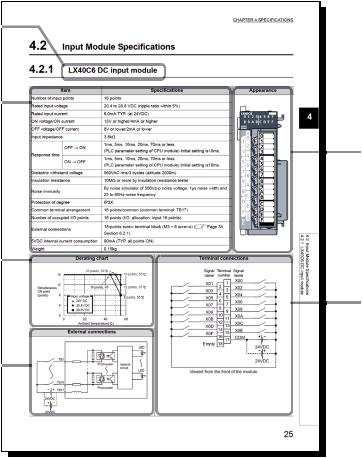
Model name and  module name
Module specifications 
Appearance
Derating chart  (only for input modules)
Terminal connections
External connections 
13
|
TERMS |
|
|
|
|
|
|
|
Unless otherwise specified, this manual uses the following terms. |
||
|
|
|
Term |
Description |
|
CPU module |
Abbreviation for the MELSEC-L series CPU module |
|
|
|
|
Power supply module |
Abbreviation for the MELSEC-L series power supply module |
|
|
|
|
Display unit |
A liquid crystal display to be attached to the CPU module |
|
|
|
|
LCPU |
Another term for the MELSEC-L series CPU module |
|
|
|
|
GX Works2 |
The product name of the software package for the MELSEC programmable controllers |
|
|
||
GX Developer |
||
|
||
|
|
|
L series I/O module |
Abbreviation for the MELSEC-L series I/O module |
|
|
|
|
Q series I/O module |
Abbreviation for the MELSEC-Q series I/O module |
|
|
|
|
I/O module |
Another term for the MELSEC-L series I/O module |
|
|
|
|
ACTB |
Abbreviation for the AC05TB, AC10TB, AC20TB, AC30TB, AC50TB, AC80TB, and AC100TB |
|
|
|
|
ACTE |
Abbreviation for the AC06TE, AC10TE, AC30TE, AC50TE, and AC100TE |
|
|
|
|
|
PACKING LIST |
|
|
|
|
|
|
|
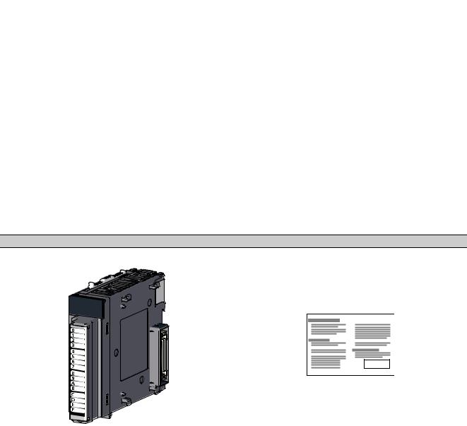
The following items are included in the package of this product. Before use, check that all the items are included.
I/O module
Module |
Before Using the Product |
|
|
14

CHAPTER 1 PRODUCT LINEUP
CHAPTER 1 PRODUCT LINEUP
1.1 Product Lineup
(1) Input module
Module name |
Input specifications |
Number of occupied |
Current |
Weight |
Model name |
Reference |
|
I/O points |
consumption |
||||||
|
|
|
|
|
|||
|
Terminal block |
16 points |
90mA |
0.17kg |
LX10 |
Page 29, |
|
|
100 to 120VAC, 16 points |
Section 4.2.1 |
|||||
AC Input module |
|
|
|
|
|||
|
|
|
|
|
|
||
Terminal block |
16 points |
80mA |
0.15kg |
LX28 |
Page 31, |
||
|
|||||||
|
100 to 240VAC, 8 points |
Section 4.2.2 |
|||||
|
|
|
|
|
|||
|
|
|
|
|
|
|
|
|
Terminal block |
16 points |
90mA |
0.15kg |
LX40C6 |
Page 32, |
|
|
24VDC, 16 points |
Section 4.2.3 |
|||||
|
|
|
|
|
|||
|
|
|
|
|
|
|
|
DC Input module |
40-pin connector |
32 points |
100mA |
0.11kg |
LX41C4 |
Page 34, |
|
24VDC, 32 points |
Section 4.2.4 |
||||||
|
|
|
|
|
|||
|
|
|
|
|
|
|
|
|
40-pin connector (× 2) |
64 points |
120mA |
0.12kg |
LX42C4 |
Page 36, |
|
|
24VDC, 64 points |
Section 4.2.5 |
|||||
|
|
|
|
|
|||
|
|
|
|
|
|
|
(2) Output module
Module name |
Output specifications |
Number of occupied |
Current |
Weight |
Model name |
Reference |
||
I/O points |
consumption |
|||||||
|
|
|
|
|
|
|||
|
|
Terminal block |
16 points |
460mA |
0.21kg |
LY10R2 |
Page 39, |
|
|
|
240VAC/24VDC, 2A/1 point, 16 points |
Section 4.3.1 |
|||||
|
|
|
|
|
|
|||
Contact output module |
|
|
|
|
|
|
||
Terminal block |
|
|
|
|
Page 40, |
|||
|
|
240VAC/24VDC, 2A/1 point, 8 points |
16 points |
260mA |
0.14kg |
LY18R2A |
||
|
|
Section 4.3.2 |
||||||
|
|
All points independent |
|
|
|
|
||
|
|
|
|
|
|
|
||
|
|
|
|
|
|
|
|
|
|
|
Terminal block |
16 points |
300mA |
0.22kg |
LY20S6 |
Page 41, |
|
|
|
100 to 240VAC, 0.6A/1 point, 16 points |
Section 4.3.3 |
|||||
|
|
|
|
|
|
|||
Triac output module |
|
|
|
|
|
|
||
Terminal block |
|
|
|
|
Page 42, |
|||
|
|
100 to 240VAC, 1A/1 point, 8 points |
16 points |
200mA |
0.15kg |
LY28S1A |
||
|
|
Section 4.3.4 |
||||||
|
|
All points independent |
|
|
|
|
||
|
|
|
|
|
|
|
||
|
|
|
|
|
|
|
|
|
|
|
Terminal block |
16 points |
100mA |
0.15kg |
LY40NT5P |
Page 44, |
|
|
|
12 to 24VDC, 0.5A/1 point, 16 points |
Section 4.3.5 |
|||||
|
|
|
|
|
|
|||
|
|
|
|
|
|
|
|
|
|
Sink type |
40-pin connector |
32 points |
140mA |
0.11kg |
LY41NT1P |
Page 45, |
|
|
12 to 24VDC, 0.1A/1 point, 32 points |
Section 4.3.6 |
||||||
|
|
|
|
|
|
|||
|
|
|
|
|
|
|
|
|
Transistor |
|
40-pin connector (× 2) |
64 points |
190mA |
0.12kg |
LY42NT1P |
Page 47, |
|
|
12 to 24VDC, 0.1A/1 point, 64 points |
Section 4.3.7 |
||||||
output |
|
|
|
|
|
|||
|
|
|
|
|
|
|
||
|
Terminal block |
|
|
|
|
Page 49, |
||
module |
|
16 points |
100mA |
0.15kg |
LY40PT5P |
|||
|
12 to 24VDC, 0.5A/1 point, 16 points |
Section 4.3.8 |
||||||
|
|
|
|
|
|
|||
|
|
|
|
|
|
|
|
|
|
Source |
40-pin connector |
32 points |
140mA |
0.11kg |
LY41PT1P |
Page 50, |
|
|
type |
12 to 24VDC, 0.1A/1 point, 32 points |
Section 4.3.9 |
|||||
|
|
|
|
|
||||
|
|
|
|
|
|
|
|
|
|
|
40-pin connector (× 2) |
64 points |
190mA |
0.12kg |
LY42PT1P |
Page 52, |
|
|
|
12 to 24VDC, 0.1A/1 point, 64 points |
Section 4.3.10 |
|||||
|
|
|
|
|
|
|||
|
|
|
|
|
|
|
|
|
(3) I/O combined module
|
|
Input |
Output |
Number of |
Current |
|
|
|
|
Module name |
occupied |
Weight |
Model name |
Reference |
|||||
specifications |
specifications |
consumption |
|||||||
|
|
I/O points |
|
|
|
||||
|
|
|
|
|
|
|
|
||
DC |
Sink type |
|
40-pin connector |
32 points |
160mA |
0.12kg |
LH42C4NT1P |
Page 54, |
|
input/transistor |
|
Section 4.4.1 |
|||||||
|
40-pin connector |
12 to 24VDC, |
|
|
|
|
|||
output |
|
|
|
|
|
|
|||
|
24VDC, 32 points |
0.1A/1 point, 32 |
|
|
|
|
Page 56, |
||
combined |
Source type |
32 points |
150mA |
0.12kg |
LH42C4PT1P |
||||
|
points |
Section 4.4.2 |
|||||||
module |
|
|
|
|
|
|
|||
|
|
|
|
|
|
|
|
||
|
|
|
|
|
|
|
|
|
|
1
Lineup Product 1.1
15

1.2 How to Read the Model Name
• For input module or output module
L Y 4 0 N T 5 P
|
|
|
|
1) |
|
|
2) |
3) |
4) |
5) |
|
|
6) |
|
|||
|
• For I/O combined module |
|
|
|
|
|
|
|
|
|
|
||||||
|
|
L H 4 2 C 4 N T 1 P |
|
||||||||||||||
|
|
|
|
|
|
|
|
|
|
|
|
|
|||||
|
|
1) |
2) |
|
|
3) |
|
Input type |
Output type |
6) |
|
||||||
|
|
|
|
|
|
|
|
|
4) |
5) |
|
4) |
5) |
|
|
||
|
|
|
|
|
|
|
|
|
|
|
|
|
|
|
|
|
|
No. |
Item |
|
Symbol |
|
|
|
|
|
|
|
|
|
Specifications |
|
|
|
|
|
|
|
X |
Input |
|
|
|
|
|
|
|
|
|
|
|||
|
|
|
|
|
|
|
|
|
|
|
|
|
|
|
|
|
|
1) |
Module type |
|
Y |
Output |
|
|
|
|
|
|
|
|
|
|
|||
|
|
|
|
|
|
|
|
|
|
|
|
|
|
|
|
|
|
|
|
|
H |
I/O combined |
|
|
|
|
|
|
|
|
|
|
|||
|
|
|
|
|
|
|
|
|
|
|
|
|
|
|
|
|
|
|
|
|
|
|
|
|
|
|
|
|
|
|
|
|
|
|
|
|
|
|
|
|
|
|
|
|
|
|
|
|
Specifications |
|
|
|
|
|
|
|
|
|
|
|
|
|
|
|
|
|
|
|
|
|
|
No. |
Item |
|
Symbol |
|
|
|
Input module |
|
|
|
|
|
Output module |
|
|||
|
|
|
|
|
AC input |
|
|
DC input |
|
|
Contact output |
|
|
Triac output |
Transistor output |
||
|
Voltage |
|
1 |
100 to 120VAC |
|
- |
|
|
24VDC/240VAC |
|
|
- |
- |
||||
|
|
|
|
|
|
|
|
|
|
|
|
|
|
|
|
|
|
2) |
|
2 |
100 to 240VAC |
|
- |
|
|
- |
|
|
100 to 240VAC |
- |
|||||
specification |
|
|
|
|
|
|
|||||||||||
|
|
|
|
|
|
|
|
|
|
|
|
|
|
|
|
|
|
|
|
|
4 |
- |
|
|
|
|
|
24VDC |
|
|
- |
|
|
- |
12 to 24VDC |
|
|
|
|
|
|
|
|
|
|
|
|
|
|
|
|
|
|
|
|
|
|
|
|
|
|
|
|
|
|
|
|
|
|
|
|
No. |
Item |
|
Symbol |
|
|
|
|
|
|
|
|
|
Specifications |
|
|
|
|
|
|
|
0 |
16 points |
|
|
|
|
|
|
|
|
|
|
|||
|
|
|
|
|
|
|
|
|
|
|
|
|
|
|
|
|
|
3) |
Number of I/O |
|
1 |
32 points |
|
|
|
|
|
|
|
|
|
|
|||
points |
|
2 |
64 points |
|
|
|
|
|
|
|
|
|
|
||||
|
|
|
|
|
|
|
|
|
|
|
|
||||||
|
|
|
|
|
|
|
|
|
|
|
|
|
|
|
|
|
|
|
|
|
8 |
8 points |
|
|
|
|
|
|
|
|
|
|
|||
|
|
|
|
|
|
|
|
|
|
|
|
|
|
|
|
|
|
|
|
|
|
|
|
|
|
|
|
|
|
|
|
|
|
|
|
No. |
Item |
|
Symbol |
|
|
|
|
|
|
|
|
|
Specifications |
|
|
|
|
|
|
|
Blank |
AC input |
|
|
|
|
|
|
|
|
|
|
|||
|
|
|
|
|
|
|
|
|
|
|
|
|
|
||||
|
|
|
C |
DC input (positive/negative common available) |
|
|
|
|
|
||||||||
|
|
|
|
|
|
|
|
|
|
|
|
|
|
|
|
||
4) |
I/O type |
|
NT |
Transistor output (sink type) |
|
|
|
|
|
|
|
||||||
|
|
|
|
|
|
|
|
|
|
|
|
|
|
|
|
||
|
PT |
Transistor output (source type) |
|
|
|
|
|
|
|
||||||||
|
|
|
|
|
|
|
|
|
|
||||||||
|
|
|
|
|
|
|
|
|
|
|
|
|
|
|
|
|
|
|
|
|
R |
Contact output |
|
|
|
|
|
|
|
|
|
|
|||
|
|
|
|
|
|
|
|
|
|
|
|
|
|
|
|
|
|
|
|
|
S |
Triac output |
|
|
|
|
|
|
|
|
|
|
|||
|
|
|
|
|
|
|
|
|
|
|
|
|
|
|
|
|
|
16

CHAPTER 1 PRODUCT LINEUP
|
|
|
|
|
|
|
|
|
1 |
|
|
|
|
|
Specifications |
|
|
|
|
|
|
|
|
|
|
|
|
|
|
No. |
Item |
Symbol |
Input module |
|
Output module |
|
|
||
|
|
|
AC input |
DC input |
Contact output |
Triac output |
Transistor output |
|
|
|
|
|
|
||||||
|
|
1 |
- |
- |
- |
1A |
0.1A |
|
|
|
|
|
|
|
|
|
|
|
|
|
Current |
2 |
- |
- |
2A |
- |
- |
|
|
|
|
|
|
|
|
|
|
|
|
5) |
4 |
- |
4mA |
- |
- |
- |
|
|
|
specifications |
|
|
|||||||
|
|
|
|
|
|
|
|
|
|
|
|
5 |
- |
- |
- |
- |
0.5A |
||
|
|
|
|
|
|
|
|
|
|
|
|
6 |
- |
6mA |
- |
0.6A |
- |
|
|
|
|
|
|
|
|
|
|
|
|
|
|
|
|
|
|
|
|
|
|
No. |
Item |
Symbol |
|
|
Specifications |
|
|
|
|
6) |
Extended |
P |
With protection function |
|
|
|
|
|
|
specification |
A |
Independent common |
|
|
|
|
|
|
|
|
|
|
|
|
|
|
|||
|
|
|
|
|
|
|
|
|
|
Name Model the Read to How 2.1
17
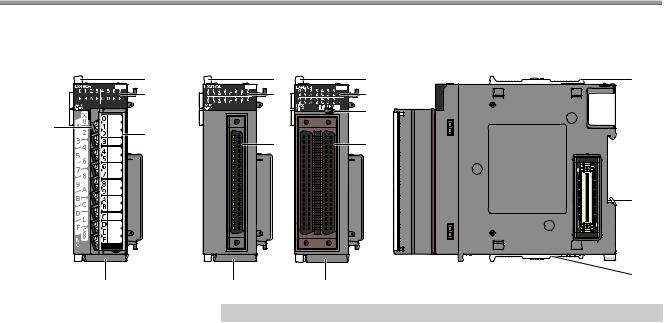
CHAPTER 2 PART NAMES
18-point screw terminal block type |
40-pin connector type |
|
1) |
|
2) |
3) |
4) |
|
|
8) |
8) |
1) |
1) |
1) |
2) |
2) |
|
|
7) |
|
6) |
6) |
|
|
|
5) |
|
|
1) |
|
8) |
|
No. |
Name |
Description |
|
1) |
Module joint levers |
Levers for connecting two modules |
|
|
|
|
|
|
|
Indicate the I/O status. |
|
2) |
I/O operation status indicator LEDs |
• On (green): I/O signal is on. |
|
|
|
• Off: I/O signal is off. |
|
|
|
|
|
3) |
Terminal block |
A 18-point terminal block for connecting I/O signal cables to external devices |
|
|
|
|
|
4) |
Terminal cover |
A cover for preventing electric shock |
|
A label on it is used for recording the signal names of devices allocated to terminals. |
|||
|
|
||
|
|
|
|
5) |
DIN rail hook |
A hook used to mount the module to a DIN rail |
|
|
|
|
|
6) |
Connectors for external devices (40 pins) |
A connector for connecting I/O signal cables to external devices. |
|
|
|
|
|
|
|
• For input module or output module: Used to switch the LED indications between the first-half 32 points |
|
7) |
Indication selector switch*1 |
and latter-half 32 points of a 64-point module. |
|
|
|
• For I/O combined module: Used to switch the LED indications between input and output. |
|
|
|
|
|
8) |
Serial number display |
Displays the serial number printed on the rating plate. |
|
|
|
|
*1 Operate the Indication selector switch with your fingers. Do not use a screwdriver or similar tool as it may damage the switch.
18
CHAPTER 2 PART NAMES
Memo
2
19
CHAPTER 3 BEFORE USING I/O MODULE
3.1 Input Module
(1)Common precautions for all output modules
(a)Simultaneous on points
The number of simultaneous on points of input module depends on the input voltage and ambient temperature. Refer to the derating chart of the input module specifications. (
 Page 28, CHAPTER 4)
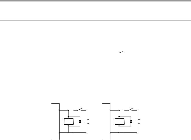
(2)Precautions for using the DC input module
(a)Measures against back EMF
When an inductive load is connected, connect a diode in parallel with the load.
Use a diode that meets the following conditions.
•Reverse breakdown voltage is equal to or more than 10 times as large as the circuit voltage.
•Forward current is equal to or more than 2 times as large as the load current.
IN |
Inductive |
load |
Diode |
COM |
Positive common
IN |
Inductive |
load |
Diode |
COM |
Negative common
20

CHAPTER 3 BEFORE USING I/O MODULE
3.2 Output Module
(1)Common precautions for all output modules
(a)Maximum switching frequency when the module drives Inductive load.
The output must be on for one second or longer and off for one second or longer.
(b) Load for connection
3
When connecting a counter or timer that has a DC-DC converter as a load, select an output module whose maximum load current is larger than inrush current of the load.
Selecting an output module by average current of the load may cause a failure of the module because inrush current flows at a constant frequency at power-on or during operation due to the connected load.
If an output module needs to be selected by average current of the load, take either of the following actions to reduce an influence from inrush current.
• Connecting a resistor to the load in series
Resistor Load
Output module
• Connecting an inductor to the load in series
Inductor Load
Output module
Module Output 2.3
21
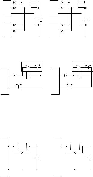
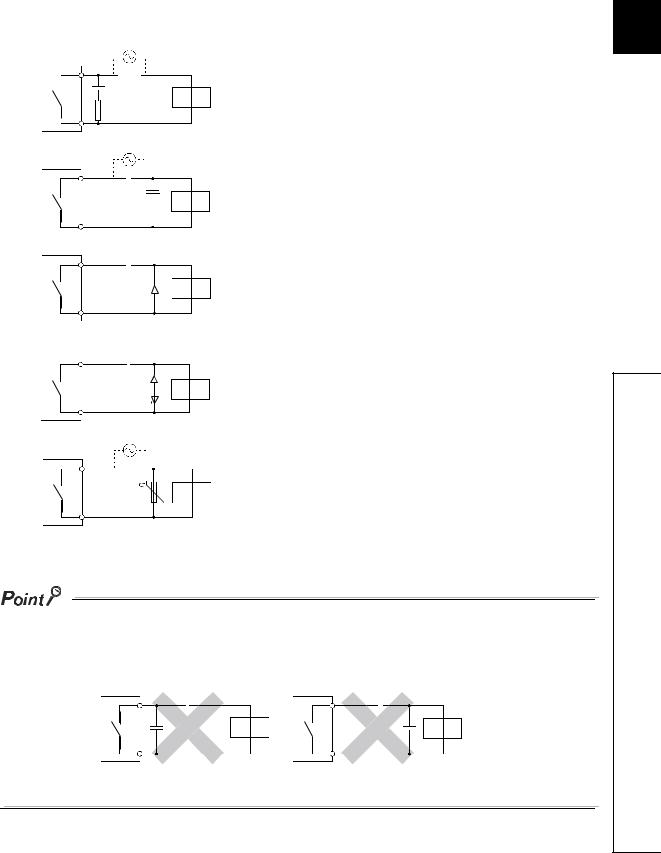
(2)Precaution for using the transistor output module
(a)Action against reverse current
If a transistor output module is wired as shown below, reverse current flows in an output element, causing a failure of the element.
When wiring a transistor output module, connect a diode as shown below.
• When connecting transistor output modules in parallel
Diode |
Load |
OUT1 |
|
Diode |
Load |
OUT2 |
|
COM |
|
Diode |
|
OUT1 |
|
Diode |
|
OUT2 |
|
COM |
|
Sink type
Diode |
Load |
OUT1 |
|
Diode |
Load |
OUT2 |
|
COM |
|
Diode |
|
OUT1 |
|
Diode |
|
OUT2 |
|
COM |
|
Source type
• When incorporating an additional circuit parallel to a transistor output module
Additional circuit |
Additional circuit |
OUT |
Diode |
COM |
OUT |
Diode |
COM |
Sink type |
Source type |
(b) Measures against back EMF
When an inductive load is connected, connect a diode in parallel with the load. Use a diode that meets the following conditions.
•Reverse breakdown voltage is equal to or more than 10 times as large as the circuit voltage.
•Forward current is equal to or more than 2 times as large as the load current.
OUT |
Inductive |
|
load |
||
|
||
|
Diode |
|
COM |
|
Sink type
OUT |
Inductive |
|
load |
||
|
||
|
Diode |
|
COM |
|
Source type
22
CHAPTER 3 BEFORE USING I/O MODULE
(3) Precautions for using the contact output module
When using the contact output module, consider the following.
•Relay life (contact switching life)
•Effects to relay life due to connected load
•Measures against back EMF
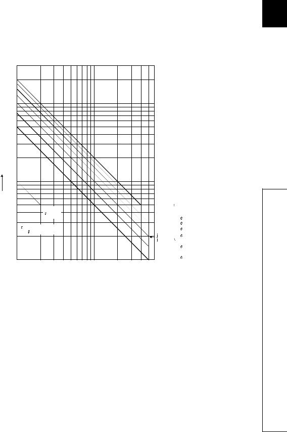
(a) Relay life (contact switching life) |
3 |
Applicable module LY10R2, LY18R2A
The relay life depends on the operating environment. Select a module according to the operating environment. The relay lives shown below are the actual service values, not the guaranteed values. Replace the module well in advance since the actual switching life may be shorter than the one shown below.
200 |
|
|
|
|
|
|
|
|
|
|
|
100 |
|
|
|
|
|
|
|
|
|
|
|
70 |
|
|
|
|
|
|
|
|
|
|
|
50 |
|
|
|
|
|
|
|
|
|
|
|
30 |
|
|
|
|
|
|
|
|
|
|
|
20 |
|
|
|
|
|
|
|
|
|
|
|
Switching life |
|
|
|
|
|
|
|
|
|
|
|
(10,000 times) |
|
|
|
|
|
|
|
|
|
|
|
10 |
|
|
|
|
|
|
|
|
|
|
|
7 |
|
|
|
|
|
|
|
|
|
|
3 |
|
|
|
|
|
|
|
|
|
|
2. |
|
|
|
|
|
|
|
|
|
|
|
|
|
5 |
|
|
|
|
|
|
|
30VDC |
=0ms |
Output |
|
|
|
|
|
|
|
|
|
||||
|
|
100VDC |
|
|
|
|
|
|
|
|
|
|
|
=7ms |
|
|
|
|
|
|
|
|
|
|
|
|
|
|
|
|
|
100VAC cos |
=0.7 |
Module |
|
3 |
|
|
|
|
|
|
|
200VAC cos |
=0.7 |
||
|
|
|
|
|
|
|
|
||||
(L/R) : Time constant |
|
|
|
|
|
100VAC cos |
=0.35 |
|
|||
cos |
: Power factor |
|
|
|
|
|
|
||||
|
|
|
|
|
|
|
|
|
|||
2 |
|
|
|
|
|
|
|
200VAC cos |
=0.35 |
|
|
|
|
|
|
|
|
|
|
24VDC |
=7ms |
|
|
|
|
|
|
|
|
|
|
120VAC cos |
=0.2 |
|
|
1 |
|
|
|
|
|
|
|
240VAC cos |
=0.2 |
|
|
|
|
|
|
|
|
|
|
|
|
|
|
0.1 |
0.2 |
0.3 |
0.5 |
0.7 |
1 |
2 |
3 |
5 |
|
|
|
 Switching current (A)
Operating environment |
Switching life |
Rated switching voltage/current, rated load |
100 thousand times |
|
|
200VAC 1.5A, 240VAC 1A (COS = 0.7) |
100 thousand times |
|
|
200VAC 0.4A, 240VAC 0.3A (COS = 0.7) |
300 thousand times |
|
|
200VAC 1A, 240VAC 0.5A (COS = 0.35) |
100 thousand times |
|
|
200VAC 0.3A, 240VAC 0.15A (COS = 0.35) |
300 thousand times |
|
|
24VDC 1A, 100VDC 0.1A (L/R = 7ms) |
100 thousand times |
|
|
24VDC 0.3A, 100VDC 0.03A (L/R = 7ms) |
300 thousand times |
|
|
23
(b) Effects to relay life due to connected load
The actual relay life may be significantly shortened compared to the relay life curve, depending on the type of a load connected and the characteristics of inrush current. (

 Page 23, Section 3.2 (3) (a)) Also, the inrush current may cause the module contact welding.
Take the following measures to prevent shortening of the relay life and the contact welding.
•Select a load so that the inrush current will be within the rated current of the module.
•Connect an external relay that can withstand the inrush current.
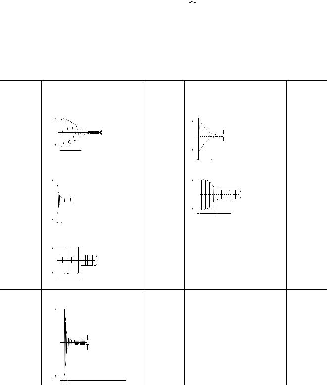
The following table shows the relation between the road and the inrush current.
Select a load so that the inrush current (i) and the rated current (io) will be within the rated switching current specified for the output module used.
The inrush current may flow for a longer time depending on the load.
|
|
|
|
Inrush current |
|
|
|
Inrush current |
|
Load type |
|
Signal waveform diagram |
(i)/rated current |
|
Signal waveform diagram |
(i)/rated current |
|||
|
|
|
|
(io) |
|
|
|
(io) |
|
|
|
Load of a solenoid |
|
Load of an electromagnetic contactor |
|
||||
Inductive load |
i |
io |
Approx. 10 to 20 |
|
|
i: Inrush current |
Approx. 3 to 10 |
||
times |
i |
io |
io: Rated current |
times |
|||||
|
|
|
|
||||||
|
|
|
i: Inrush current |
|
|
|
|
|
|
|
|
|
io: Rated current |
|
|
0.017 to 0.033 seconds |
|
||
|
|
0.07 to 0.1 seconds |
|
|
(1 to 2 cycles) |
|
|||
|
|
|
|
|
|
|
|||
|
|
|
|
|
|||||
|
Load of an incandescent bulb |
|
Load of a mercury lamp |
|
|||||
|
|
|
|
Approx. 3 to 10 |
i |
|
io |
Approx. 3 times*1 |
|
|
i |
|
io |
times |
|
||||
|
|
|
|
i: Inrush current |
|
||||
|
|
|
i: Inrush current |
|
|
|
|
||
|
|
|
|
|
|
io: Rated current |
|
||
|
|
|
io: Rated current |
|
|
|
|
||
|
|
|
|
|
180 to 300 seconds |
|
|||
|
|
|
Approx. 0.33 seconds |
|
|
|
|||
Lamp load |
|
|
|
(3 to 5 minutes) |
|
||||
|
|
|
|
|
|||||
|
Load of a fluorescent |
|
|
|
|
|
|||
|
i |
|
io |
Approx. 5 to 10 |
|
|
|
|
|
|
|
times |
|
|
|||||
|
|
|
|
|
|
||||
i: Inrush current
io: Rated current
Within 10 seconds
Capacitive load*2
Capacitive load |
Approx. 20 to 40 |
|
|
|
times |
||||
i |
|
|
||
io |
|
|
i: Inrush current io: Rated current
0.008 to 0.33 seconds
(0.5 to 2 cycles)
*1 Typical electric-discharge lamp circuit includes discharge tubes, transformers, choke coils, and capacitors. Therefore, note that the inrush current may flow 20 to 40 times as large as the rated current in the case of high power factor and low power impedance.
*2 When the wiring of the circuit is long, take care of the wire capacity.
24
CHAPTER 3 BEFORE USING I/O MODULE
(c) Measures against back EMF
Configure a contact protection circuit for extending the contact life, preventing noise when the contact is cut off, and suppressing the generation of carbide and nitric acid due to arc discharge.
An Incorrect contact protection circuit may cause contact welding.
Also, when using the contact protection circuit, the recovery time may be long.
The following table shows the representative examples of the contact protection circuit.
|
Example |
|
|
|
Method for selecting elements |
Remarks |
||||||||||||||||||||||||
|
*1 |
|
|
|
|
|
|
|
|
|
|
|
|
Refer to the following for constants of the |
|
|||||||||||||||
|
|
|
|
|
|
|
|
|
|
|
|
|
|
|
|
|
|
|
|
|
|
|
|
|
|
|
|
|
|
|
|
|
|
|
|
|
|
|
|
|
|
|
|
|
|
|
|
|
|
|
|
|
|
|
|
|
|
|
|
capacitor and resistor. Note that the |
|
|
|
|
|
|
|
|
|
|
|
|
|
|
|
|
|
|
|
|
|
|
|
|
|
|
|
|
|
|
|
|
|
|
|
|
|
|
|
|
|
|
|
|
|
|
|
|
|
|
|
|
|
|
|
|
|
|
|
|
|
following values may differ depending on a |
|
|
|
|
|
|
|
|
|
|
|
|
|
|
|
|
|
|
|
|
|
|
|
|
|
|
|
|
|
|
|
|
|
|
|
|
Capacitor |
Inductive |
|
|
nature of the load and a variation of |
If a load is a relay or solenoid, the recovery |
|||||||||||||||||||||
|
|
|
|
|
|
|||||||||||||||||||||||||
|
|
|
|
|
|
|
|
|
|
|
|
|
|
|
|
|
|
|
|
|
|
|
|
|
|
|
|
|||
|
|
|
|
Resistor |
load |
|
|
characteristics of it. |
||||||||||||||||||||||
|
|
|
|
|
|
|||||||||||||||||||||||||
|
|
|
|
|
|
|
time delays. |
|||||||||||||||||||||||
Capacitor + Resistor |
|
|
|
|
|
|
|
|
|
|
|
|
|
|
|
|
|
|
|
|
|
|
|
|
|
|
|
|
• Capacitor: 0.5 to 1(µF) against load |
|
|
|
|
|
|
|
|
|
|
|
|
|
|
|
|
|
|
|
|
|
|
|
|
|
|
|
|
|
A capacitor suppresses electric discharge |
||
method (CR |
|
|
|
|
|
|
|
|
|
|
|
|
|
|
|
|
|
|
|
|
|
|
|
|
|
|
|
|
current of 1A |
|
|
|
|
|
|
|
|
|
|
|
|
|
|
|
|
|
|
|
|
|
|
|
|
|
|
|
|
|
while a contact is off, and a resistor |
||
method) |
|
|
|
|
|
|
|
|
|
|
|
|
|
|
|
|
|
|
|
|
|
|
|
|
|
|
|
|
• Resistor: 0.5 to 1( ) against power |
|
|
|
|
|
|
|
|
|
|
|
|
|
|
|
|
|
|
|
|
|
|
|
|
|
|
|
|
|
restricts a flow of current while a contact is |
||
|
|
|
|
|
|
|
|
|
|
|
|
|
|
|
|
|
|
|
|
|
|
|
|
|
|
|
|
|
supply voltage of 1V |
|
|
|
|
|
|
|
|
|
|
|
|
|
|
|
|
|
|
|
|
|
|
|
|
|
|
|
|
|
|
on. |
|
|
|
|
|
|
|
|
|
|
|
|
|
|
|
|
|
|
|
|
|
|
|
|
|
|
|
|
|
|
Use a capacitor whose withstand voltage is |
|
|
|
|
|
|
|
|
|
|
|
|
|
|
|
|
|
|
|
|
|
|
|
|
|
|
|
|
|
|
equal to or more than the rated voltage. In |
|
|
|
|
|
|
|
|
|
|
|
|
|
|
|
|
|
|
|
|
|
|
|
|
|
|
|
|
|
|
|
|
|
|
|
|
Capacitor |
|
Inductive |
|
|
|
|||||||||||||||||||||
|
|
|
|
|
|
|
AC circuit, use a capacitor having no |
|
||||||||||||||||||||||
|
|
|
|
|
|
|
|
|
|
|
|
|
|
|
|
|
|
|
|
|
|
|
|
|
|
|
|
|
||
|
|
|
|
Resistor |
|
|
|
|
|
|
|
|
|
load |
|
|
polarity. |
|
||||||||||||
|
|
|
|
|
|
|
|
|
|
|
|
|
|
|
|
|
||||||||||||||
|
|
|
|
|
|
|
|
|
|
|
|
|
|
|
|
|
|
|
|
|
|
|
|
|
|
|
|
|
|
|
|
|
|
|
|
|
|
|
|
|
|
|
|
|
|
|
|
|
|
|
|
|
|
|
|
|
|
|
|
|
|
|
|
|
|
|
|
|
|
|
|
|
|
|
|
|
|
|
|
|
|
|
|
|
|
|
|
|
|
|
Use a diode that meets both conditions |
|
|
|
|
|
|
|
|
|
|
|
|
|
|
|
|
|
|
|
|
|
|
|
|
|
|
|
|
|
|
shown below. |
|
|
|
|
|
|
|
|
|
|
|
|
|
|
|
|
|
|
|
|
|
|
|
|
|
|
|
|
|
|
• Reverse breakdown voltage is equal to |
The recovery time is slower than the CR |
|
|
|
|
|
|
|
|
|
|
|
|
|
|
|
|
|
|
|
|
|
|
|
|
|
|
|
|
|
||
|
|
|
|
|
|
|
|
|
|
|
|
|
|
|
|
|
|
|
|
|
|
|
|
|
|
|
|
|
|
|
Diode method |
|
|
|
|
|
|
|
|
|
|
|
|
|
|
|
|
|
|
|
|
|
|
|
|
|
Inductive |
|
|
or more than 10 times as large as the |
|
|
|
|
|
|
|
|
Diode |
|
|
|
|
|
|
load |
|
|
method. |
|||||||||||||
|
|
|
|
|
|
|
|
|
|
|
|
|
circuit voltage. |
|||||||||||||||||
|
|
|
|
|
|
|
|
|
|
|
|
|
|
|
|
|
|
|
|
|
|
|
|
|
|
|
|
|
||
|
|
|
|
|
|
|
|
|
|
|
|
|
|
|
|
|
|
|
|
|
|
|
|
|
|
|
|
|
|
|
|
|
|
|
|
|
|
|
|
|
|
|
|
|
|
|
|
|
|
|
|
|
|
|
|
|
|
|
|
• The forward current is equal to or more |
|
|
|
|
|
|
|
|
|
|
|
|
|
|
|
|
|
|
|
|
|
|
|
|
|
|
|
|
|
|
than 2 times as large as the load current. |
|
|
|
|
|
|
|
|
|
|
|
|
|
|
|
|
|
|
|
|
|
|
|
|
|
|
|
|
|
|
|
|
Diode + Zener diode |
|
|
|
|
|
|
|
|
|
|
|
|
|
|
|
|
|
|
|
|
|
|
|
|
|
|
|
|
Use zener voltage for the zener diode |
This method is effective when the recovery |
|
|
|
|
|
|
|
|
|
|
|
|
|
|
|
|
|
|
|
|
|
|
|
|
|
|
|
|
|||
|
|
|
|
|
|
|
|
|
|
|
|
|
|
|
|
|
|
|
|
|
|
|
|
|
|
|
|
|||
method |
|
|
|
|
|
|
|
Diode |
|
|
|
|
|
|
Inductive |
|
|
equal to or more than the power supply |
time delays considerably by the diode |
|||||||||||
|
|
|
|
|
|
|
|
|
|
|||||||||||||||||||||
|
|
|
|
|
|
|
|
|
|
|
|
|
|
|
|
|
|
|
|
|
|
|
|
|
|
|
voltage. |
method. |
||
|
|
|
Zener Diode |
|
|
|
|
|
|
|
|
|
load |
|
|
|||||||||||||||
|
|
|
|
|
|
|
|
|
|
|
|
|
|
|||||||||||||||||
|
|
|
|
|
|
|
|
|
|
|
|
|
|
|
|
|
|
|
|
|
|
|
|
|
|
|
|
|
|
|
|
|
|
|
|
|
|
|
|
|
|
|
|
|
|
|
|
|
|
|
|
|
|
|
|
|
|
|
|
Select a cut voltage (Vc) for the varistor to |
|
|
|
|
|
|
|
|
|
|
|
|
|
|
|
|
|
|
|
|
|
|
|
|
|
|
|
|
|
|
meet the following condition. |
|
|
|
|
|
|
|
|
|
|
|
|
|
|
|
|
|
|
|
|
|
|
|
|
|
|
|
|
|
|
• Vc > Power voltage × 1.5(V) |
|
Varistor method |
|
|
|
|
|
|
|
|
|
|
|
|
|
|
|
|
|
|
|
|
|
|
|
|
|
|
|
|
• Vc > Power supply voltage × 1.5(V) × √2 |
The recovery time delays slightly. |
|
|
|
|
|
|
|
|
|
|
|
|
|
|
|
|
|
|
|
|
|
|
|
|
|
|
|
|
|||
|
|
|
|
|
|
|
|
|
|
|
|
|
|
|
|
|
|
|
|
|
|
|
|
|
|
|
|
|||
|
|
|
|
Varistor |
|
|
|
|
|
|
|
|
|
Inductive |
|
(when using AC power supply) |
|
|||||||||||||
|
|
|
|
|
|
|
|
|
|
|
|
|
load |
|
|
|||||||||||||||
|
|
|
|
|
|
|
This method is not effective when the Vc is |
|
||||||||||||||||||||||
|
|
|
|
|
|
|
|
|
|
|
|
|
|
|
|
|
|
|
|
|
|
|
|
|
|
|
|
|
|
|
|
|
|
|
|
|
|
|
|
|
|
|
|
|
|
|
|
|
|
|
|
|
|
|
|
|
|
|
|
too high |
|
|
|
|
|
|
|
|
|
|
|
|
|
|
|
|
|
|
|
|
|
|
|
|
|
|
|
|
|
|
|
|
*1 When using AC power, impedance of CR must be larger enough than it of the load (prevention of a malfunction due to leak current from the CR).
●Avoid providing a contact protection circuits shown below.
These circuit are effective for preventing an arc at shut-off. However, the contact welding may occur because the charge current flows to capacitor when the contact turns on or off.
A DC inductive load is usually harder for switching than a resistor load, but if a proper protection circuit is configured, the performance will be similar to the resistor load.
|
|
|
|
|
|
|
|
|
|
|
|
|
|
|
|
|
|
|
|
|
|
|
|
|
|
|
|
|
|
|
|
|
|
|
|
|
|
|
|
|
|
|
|
|
|
|
|
|
|
|
|
|
|
|
|
|
|
|
|
|
|
|
|
|
|
|
|
|
|
|
|
|
|
|
|
|
|
|
|
|
|
|
|
Capacitor |
Inductive |
|
Capacitor |
Inductive |
||||||||||||||||
|
||||||||||||||||||||
load |
|
load |
||||||||||||||||||
|
|
|
|
|
|
|
|
|
|
|
|
|
|
|
|
|
|
|
||
●A protection circuit must be provided closely to a load or contact (module). If their distance is far, the protection circuit may not be effective. Appropriate distance is within 50 cm.
3
Module Output 2.3
25
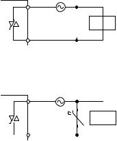
(4)Precautions for using the triac output module
(a)Measures against back EMF
Take measures against back EMF to the side where the load is connected if the wiring distance from the output module to the load is long.
If not, the surge suppressor in the output module may not work effectively.
|
|
Example |
|
|
Method for selecting elements |
Remarks |
||||||
|
|
|
|
|
|
|
|
|
|
|
Refer to the following for constants of the |
|
|
|
|
|
|
|
|
|
|
|
|
capacitor and resistor. Note that the |
|
|
|
|
|
|
|
|
|
|
|
|
following values may differ depending on a |
|
|
|
|
|
|
|
|
|
|
|
|
nature of the load and a variation of |
|
Capacitor + Resistor |
|
|
|
|
|
|
|
|
|
|
characteristics of it. |
If a load is a relay or solenoid, the recovery |
|
|
|
|
|
|
|
|
|
|
|||
|
|
|
|
Capacitor |
|
|
|
|
|
• Capacitor: 0.5 to 1(µF) against load |
||
method (CR |
|
|
|
|
|
|
|
Inductive |
|
|||
|
|
|
|
|
|
|
|
|||||
|
|
|
|
|
|
|
|
|
current of 1A |
time delays. |
||
method) |
|
|
|
|
Resistor |
|
|
load |
|
|||
|
|
|
|
|
|
|
• Resistor: 0.5 to 1( ) against power |
|
||||
|
|
|
||||||||||
|
|
|
|
|
|
|
|
|
|
|
|
|
|
|
|
|
|
|
|
|
|
|
|
|
|
|
|
|
|
|
|
|
|
|
|
|
supply voltage of 1V |
|
|
|
|
|
|
|
|
|
|
|
|
Use a capacitor whose withstand voltage is |
|
|
|
|
|
|
|
|
|
|
|
|
equal to or more than the rated voltage. |
|
|
|
|
|
|
|
|
|
|
|
|
Use a capacitor having no polarity. |
|
|
|
|
|
|
|
|
|
|
|
|
|
|
|
|
|
|
|
|
|
|
|
|
|
Select a cut-off voltage (Vc) for the varistor |
|
|
|
|
|
|
|
|
|
|
|
|
to meet the following condition. |
|
Varistor method |
|
|
|
|
|
|
|
|
|
• Vc > Power supply voltage × 1.5(V) × √2 |
The recovery time delays slightly. |
|
|
|
|
|
Varistor |
|
|
Inductive |
|
||||
|
|
|
|
|
|
|
||||||
|
|
|
|
|
|
load |
|
This method is not effective when the Vc is |
|
|||
|
|
|
|
|
|
|
||||||
|
|
|
|
|
|
|
|
|
|
|
|
|
|
|
|
|
|
|
|
|
|
|
|
too high. |
|
|
|
|
|
|
|
|
|
|
|
|
|
|
26

CHAPTER 3 BEFORE USING I/O MODULE
3.3 I/O Combined Module
This section describes the precautions for using the I/O combined module.
The precautions not described below are common to that for the input module and output module. (
 Page 20, Section 3.1, Page 21, Section 3.2)
(1) I/O numbers of the I/O combined module
The I/O combined module uses same I/O number for input and output.
Because same number is used for input and output, the I/O numbers to be used can be saved.
Input (X) |
Output (Y) |
|
|
|
|
X00 |
Y00 |
|
|
|
32 points |
X1F |
Y1F |
|
|
|
|
(2) Applicable software
Use GX Works2 with version 1.492N or later.
The following cannot be set using GX Developer and GX Works2 whose version is earlier than 1.492N.
•"I/O Mix" cannot be selected in I/O Assignment.
•Input response time cannot be set.
•Error Time Output Mode cannot be set.
3
Module Combined I/O 3.3
27

CHAPTER 4 SPECIFICATIONS
4.1 General Specifications
For the general specifications of the I/O modules, refer to the following manual.  Manual "Safety Guidelines" included in the CPU module or head module
28
Loading...