

Mitsubishi Electric 55624R(S)-MF Service Manual
54-l
CHASSIS
ELECTRICAL
CONTENTS
M54AA”
AUDIO SYSTEM
.......................................................
112
Antenna Assembly
.................................................
153
Feeder Cable
.........................................................
155
Power Amplifier
.....................................................
151
Radio and Tape
Player
.............................................
. 49
Service Adjustment Procedures
...............................
148
Speaker
................................................................
151
Specifications
........................................................
1 12
Torque Specifications
.........................................
1 12
Troubleshooting
.....................................................
1 12
BATTERY
.................................................................
2
Service Adjustment Procedures
...............................
4
Specifications
........................................................
2
General Specifications
........................................
2
Troubleshooting
.....................................................
3
CIGARETTE LIGHTER
...............................................
106
Cigarette Lighter
....................................................
108
Specifications
........................................................
106
General Specifications
........................................
106
Troubleshooting
.....................................................
106
CLOCK
_......._.....,
......................................................
109
Specifications
........................................................
109
General Specifications
........................................
109
Troubleshooting
.....................................................
109
COLUMN SWITCH...._._...___
.......................................
100
Column Switch
......................................................
101
Specifications
........................................................
100
General Specifications
........................................
100
Torque Specifications
.........................................
100
HORN
...................................
.._
................................
103
Horn
.....................................................................
105
Relay
....................................................................
105
Specifications
........................................................
103
General Specifications
........................................
103
Troubleshooting
.....................................................
104
IGNITION SWITCH
.........................
.._
.......................
6
Ignition Switch
...............................................
___._
...
6
LIGHTING SYSTEM...._....._...........................__..._.__
...
36
Fog
Light
..............................................................
94
Fog Light Switch
...................................................
99
Hazard Switch
.......................................................
98
Headlights
.............................................................
92
High Mounted Stop Light
.......................................
96
Rear Combination Light
..........................................
95
Relay
....................................................................
Rheostat
...............................................................
Service
Adjustment
Procedures
...............................
Special Tools
.........................................................
Specifications
........................................................
General Specifications
........................................
Sealants
and
Adhesives
.....................................
Service Specifications
.........................................
Troubleshooting
.....................................................
METERS AND GAUGES
............................................
Meters and Gauges
...............................................
Service Adjustment Procedures
...............................
Inspection
.........................................................
Specifications
........................................................
General Specifications
........................................
Sealants and Adhesives
.....................................
Service Specifications
.........................................
Torque
Specifications
.........................................
Troubleshooting
.....................................................
97
99
89
40
38
38
40
40
41
8
33
29
29
8
8
10
9
10
12
REAR
WINDOW
DEFOGGER
.....................................
156
-
Defogger Relay
.....................................................
163
Defogger Timer
.....................................................
164
Rear Window Defogger Switch
...............................
163
Service
Adjustment
Procedures
...............................
162
Troubleshooting
.....................................................
156
THEFT-ALARM SYSTEM
...........................................
165
Special Tools
.........................................................
165
Troubleshooting
.....................................................
165
ACTIVE-ELECTRONIC CONTROL
SUSPENSION
. . . . . . . . . . . . . . . . . . . . . . . . . . . . .
REFER
TO
GROUP
338
AIR CONDITIONING
. . . . . . . . . . . . . . . . . . . . .
REFER TO GROUP 55
ANTI-LOCK BRAKING SYSTEM . . . . REFER TO GROUP 35
&JT&RUISE
CONTROL
. . . . . . . . . . . . . . . . . . . . . . . . . . . . . . . . . . . . . . .
REFER TO GROUP 13
CENTRAL DOOR LOCKING
SYSTEM
. . . . . . . . . . . . . . . . . . . . . . . . . . . . . . . . . . . . . . .
REFER
TO GROUP 42
ELECTRONIC CONTROL
DOOR
MIRROR
............................
REFER
TO GROUP
51
HEATER
.......................................
REFER
TO GROUP
55
POWER
WINDOW ........................
REFER
TO GROUP 42
RADIATOR FAN MOTOR
..............
REFER TO GROUP 14
gE& e,Etr,
(AUTOMATIC
..................................
REFER TO GROUP 52
SUNROOF
....................................
REFER
TO GROUP 42
;V~D&;lELD
WIPER AND
. . . . . . . . . . . . . . . . . . . . . . . . . . . . . . . . . . . . . .
REFER TO GROUP 51
54-2
BATTERY -
Smxifications
BATTERY
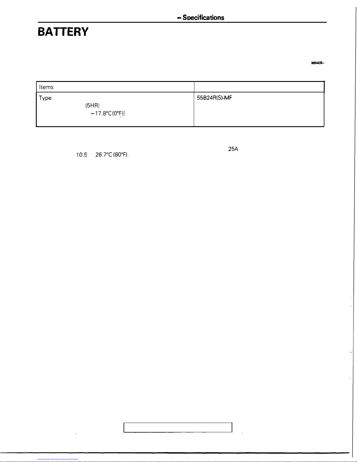
SPECIFICATIONS
GENERAL SPECIFICATIONS
BATTERY
Items
Specifications
Type
Ampere hours
(5HR)
Ah
Cranking rating [at -
17.8”C (O”F)I
Reserve capacity
min.
A
55624R(S)-MF
40
433
79
NOTES
1. CRANKING RATING is the current a
greater at a specified temperature.
2. RESERVE CAPACITY RATING is the
voltage of
10.5
at
26.7”C (80°F).
battery can deliver for 30 seconds and maintain a terminal voltage of 7.2 or
amount of time a battery can deliver
25A
and maintain a minimum terminal
TSB Revision
BATTERY - Troubleshooting
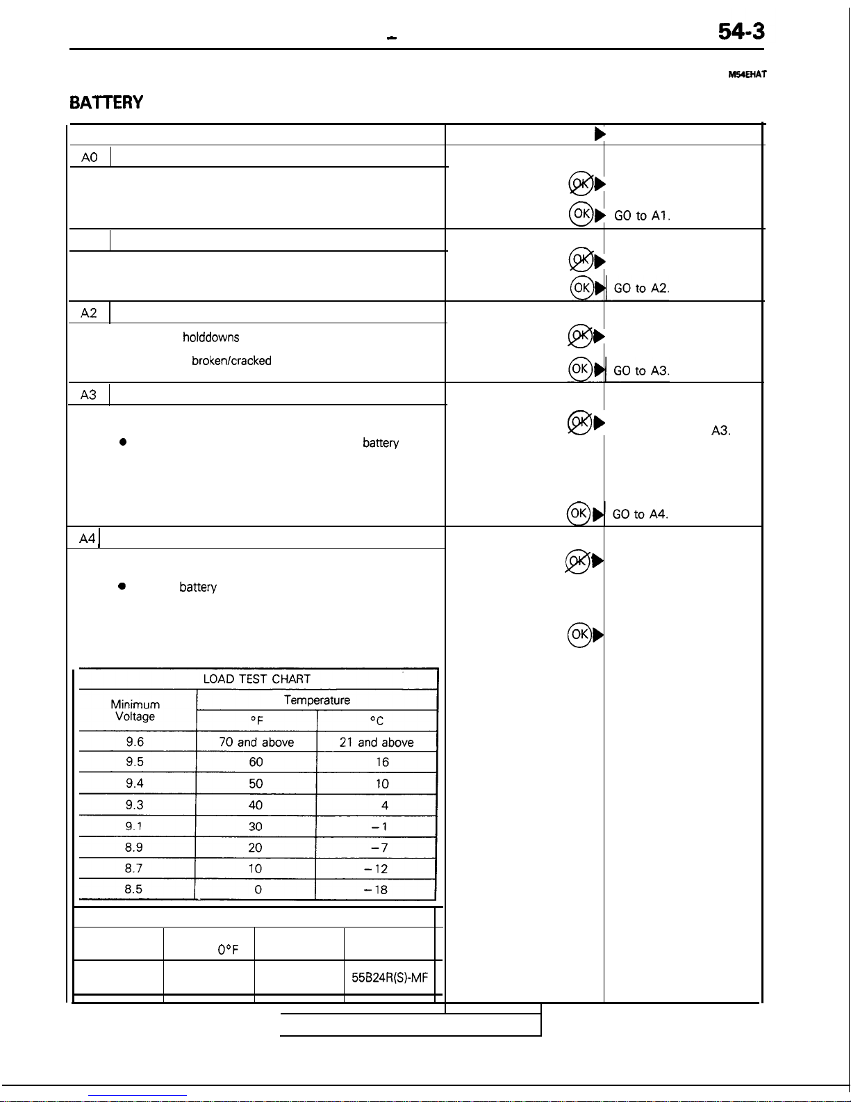
TROUBLESHOOTING
BAlTERY
TESTING PROCEDURE
TEST STEP
RESULT
b
ACTION TO TAKE
A0
VISUAL INSPECTION
l
Remove negative cable, then positive cable.
)
CLEAN terminals and
clamps. GO to Al.
l
Check for dirty or corroded connections.
0
OK) GOtoAl.
Al
LOOSE BATTERY POST
l
Check for loose battery post.
@
)
REPLACE battery.
A2
CRACKED BATTERY ‘COVER
l
Remove
holddowns
and shields.
@
)
REPLACE battery.
l
Check for
broken/cracked
case or cover.
A3
TEST INDICATOR/OPEN CIRCUIT VOLTAGE TEST
l
Turn headlights on for 15 seconds
0
Turn headlights off for 2 minutes to allow
battery
voltage to stabilize.
l
Disconnect cables.
l
Read open circuit voltage.
A4 1
LOAD TEST
@b
CHARGE battery at 5
Blue dot invisible and’
amps then GO to
A3.
open circuit voltage under
12.4 volts
l
Connect a load tester to the battery.
0
Load the
battery
at the recommended discharge rate
(see LOAD TEST RATE CHART) for 15 seconds.
l
Read voltage after 15 seconds, then remove load.
@
)
REPLACE battery.
Voltage is less than
minimum listed (white
indicator).
0,
OK
Battery OK.
Voltage is more than
minimum listed.
Load Test
(Amps)
210 amps
LOAD TEST RATE CHART
Cranking
Reserve
Rating
O°F
Capacity
433 amps
79 minutes
Application
55B24R(S)-MF
TSB Revision
Vent plug
\
BATT’ERY -
Service Adjustment Procedures
SERVICE ADJUSTMENT PROCEDURES
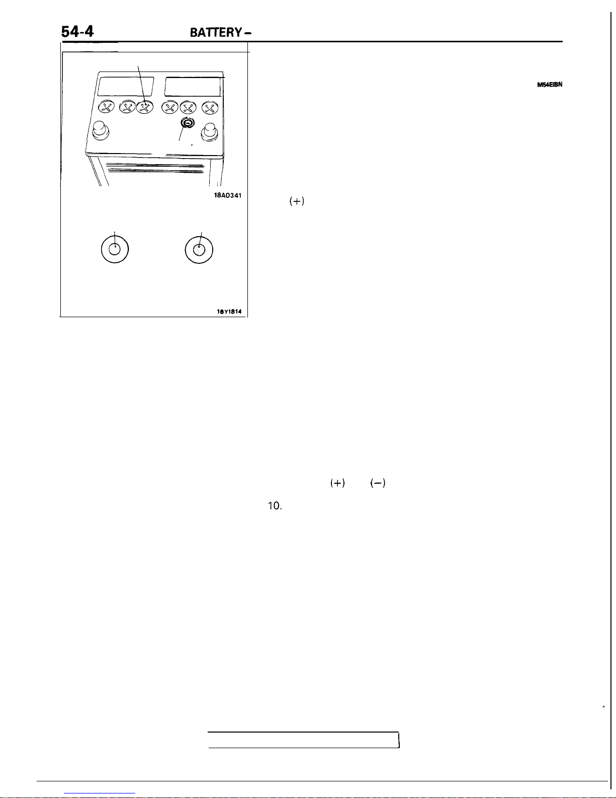
Indicator
18A0341
White
Blue
Charging
necessary
Good
condition
18Y1814
BATTERY INSPECTION
M!XEl8N
BATTERY VISUAL INSPECTION (1)
The battery contains a visual test indicator which gives blue
signal when an adequate charge level exists, and white signal
when charging is required.
BATTERY VISUAL INSPECTION (2)
Make sure ignition switch is in Off position and all battery feed
accessories are Off.
1.
Disconnect ground cable from battery before disconnecting
(+)
cable.
2. Remove battery from vehicle.
Caution
Care should be taken in the event battery case is
cracked or leaking to protect hands from the electrolyte. A suitable pair of rubber gloves
(not
the household type) should be worn when removing battery by
hand.
3.
Inspect battery carrier for damage caused by loss of acid
from battery. If acid damage is present, it will be necessary
to clean area with a solution of clean warm water and
baking soda. Scrub area with a stiff bristle brush and wipe
off with a cloth moistened with ammonia or baking soda in
water.
4. Clean top of battery with same solutions as described in
Step (3).
5. Inspect battery case and cover for cracks. If cracks are
present, battery must be replaced.
6.
Clean the battery post with a suitable battery post cleaning
tool.
7. Clean the inside surfaces of the terminal clamps with a
suitable battery terminal cleaning tool. Replace damaged or
frayed cables and broken terminals clamps.
8. Install the battery in vehicle.
9. Connect (+) and
(-)
cables to battery in the order of
mention.
IO.
Tighten the clamp nut securely.
TSB Revision
BATTERY - Service Adjustment Procedures
54-5
I
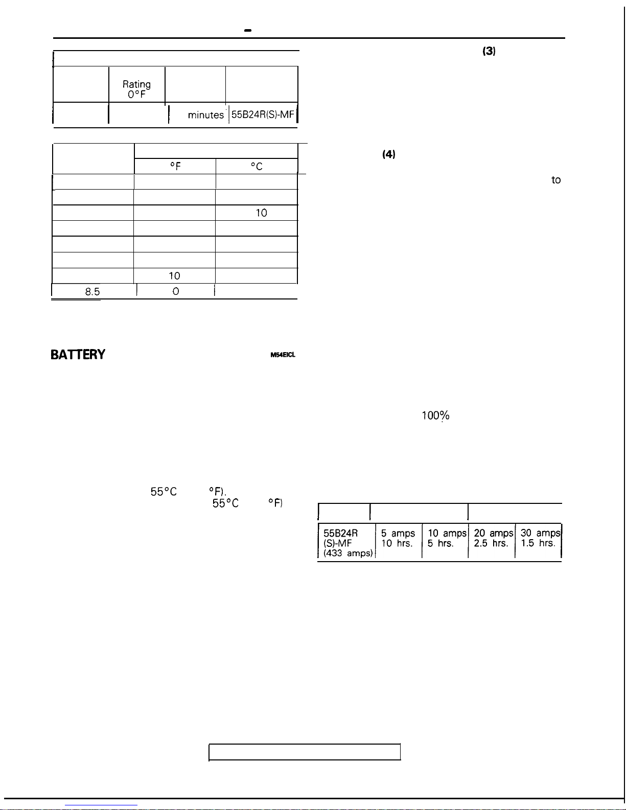
LOAD TEST RATE CHART
I
Load
Test
(Amps)
Cranking
REg
Reserve
Capacity
Application
I
210 amps
1
433 amps 1 79
minutes.1 55B24R(S)-MF (
I
LOAD TEST CHART
I
Minimum
Voltage
Temperature
OF
OC
L
9.6
70 and above
21 and above
9.5
60
16
9.4
50
10
9.3
40
4
9.1
30
-1
8.9
20
-7
8.7
10
-12
1
I 0
I
-18
I
Note
The temperature is an ambient temperature of the battery
that has been exposed to for the preceding few hours.
BA-ITERY
CHARGING
MYEICL
Caution
When batteries are being charged, an explosive
gas forms beneath the cover of each cell. Do not
smoke near batteries on charge or which have
recently been charged.
Do not break live circuits at the terminals of the
batteries on charge. A spark will occur where the
live circuit is broken.
Keep all open flames away from the battery.
Battery electrolyte temperature may temporarily be
allowed to rise to
55OC
(131
OF).
Increase of
electrolyte temperature above
55OC
(131 “F) is
harmful to the battery, causing deformation of battery
cell, decrease in life of battery, etc.
CHARGE RATE
If the test indicator is white, the battery should be
charged as outlined below.
OPEN CIRCUIT VOLTAGE TEST
(3)
1. Turn headlights on for 15 seconds.
2.
Turn headlights off for 2 minutes to allow battery
voltage to stabilize.
3. Disconnect cables.
4. Read open circuit voltage.
5. If the open circuit voltage is under 12.4 volts,
charge the battery. (See BATTERY CHARGING)
LOAD TEST
(4)
1. Connect a load tester to the battery.
2. Load the battery at 15 amps for 15 seconds to
remove surface charge.
3. Load the battery at the recommended discharge
rate. (See LOAD TEST RATE CHART)
4. Read voltage after 15 seconds and then remove
the load.
5. If the voltage is not maintained at the minimum
voltage in the LOAD TEST CHART throughout the
test, the battery should be replaced.
TSB Revision
When the dot appears or when maximum charge
shown below is reached, charging should be
stopped.
NOTE
When the charging is performed at 5 amps,
charging is virtually
loo:!
three hours after the
indicator’s indication changes from white to blue.
Use fast charging only in an emergency.
If the indicator does not turn to blue even after the
battery is charged, the battery should be replaced;
do not overcharge.
Charge Rate Chart
1
Battery 1 Slow Charging
1
Fast Charging
I
54-6
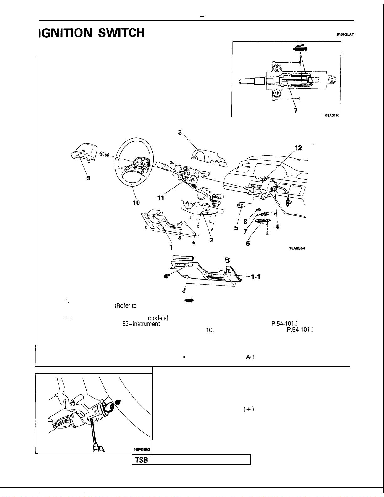
IGNITION SWITCH - Ignition Switch
IGNITION SWITCH
REMOVAL AND INSTALLATION
Removal steps
d
I.
Instrument panel under cover
4*
(1989 models]
(Referto
GROUP 52-
::
Instrument Panel.)
l 4
7.
I-1 Knee protector [From 1990
models]
l 4
8.
(Refer to GROUP
52-Instrument
Panel.)
9.
2.
Column cover lower
10.
3.
Column cover upper
11.
4.
ignition switch segment
12.
Steering lock cylinder
Cover*
Key interlock cable*
Slide lever*
Horn pad (Refer to
P.54-101.)
Steering wheel (Refer to
P.54-101.)
Column switch
Key reminder switch segment
NOTE
*
indicates vehicles with M safety-lock system.
\\
\
\
\
SERVICE POINTS OF REMOVAL
5. REMOVAL OF THE STEERING LOCK CYLINDER
(1) Insert the key in the steering lock cylinder and turn it to
the “ACC” position.
(2) Using a cross-tip
(+)
screwdriver (small) or a similar
tool, push the lock pin of the steering lock cylinder
inward and then pull the steering lock cylinder toward
you.
16POl63
TSB
Revision
IGNITION SWITCH
-
ignition Switch
54-7
Connector A
16A0570
Connector
B
16A0642
Key interlock cable
OQAO12.5
Apply grease
k
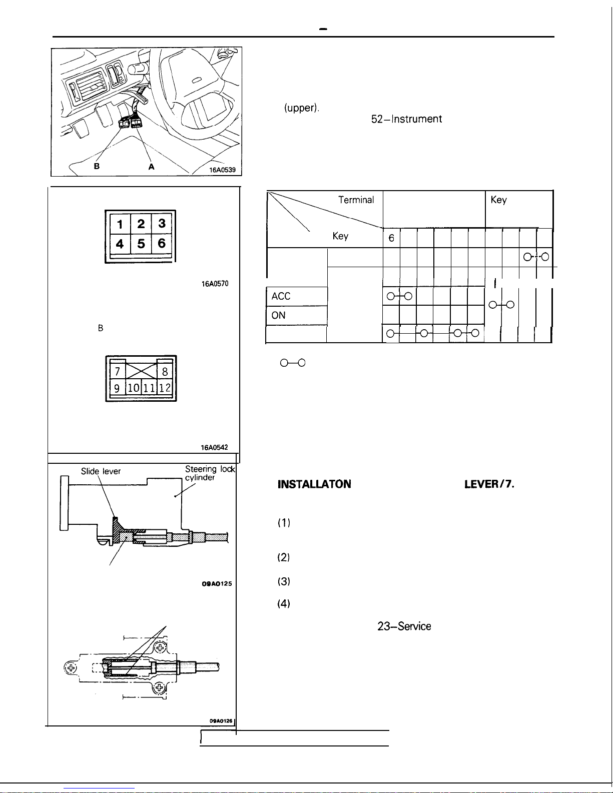
INSPECTION
IGNITION SWITCH INSPECTION
(1) Remove the instrument panel under cover (or knee
protector), the column cover (lower), and the column cover
(upped.
(Refer to GROUP
52-Instrument
Panel).
(2) Disconnect the wiring connector from the ignition switch
and key reminder switch, and connect an ohmmeter to the
switch side connector.
(3) Operate the switch, and check the continuity between the
terminals.
Ignition switch
Key
reminder
switch
Position
Key
6 3
4
2 5
17
8
912
Removed
o--o
LOCK
I
I
I I I I
o--o
Inserted
o-u-o--o
r I 1 I
START
o( ;3;
;qq
(1 1
1
NOTE
(1)
O-O
indicates that there is continuity between the terminals.
(2) O---O indicates vehicles with ETACS.
SERVICE POINTS OF INSTALLATION
8.
INSTALLATON
OF THE SLIDE LEVERi7. KEY
INTERLOCK CABLE (STEERING LOCK ASSEMBLY
SIDE)
(1)
With the ignition key either at the “LOCK” position or
removed, install the slide lever to the steering lock
cylinder.
(2)
Connect, as shown in the figure, the key interlock cable
to the slide lever and the steering lock cylinder.
(3)
Apply a light coating of multi-purpose grease where
shown in the figure.
(4)
Check whether or not the key interlock system is
functioning normally.
(Refer to GROUP
23-Service
Adjustment Procedures.)
1
TSB Revision
I
54-8
METERS AND GAUGES - Specifications
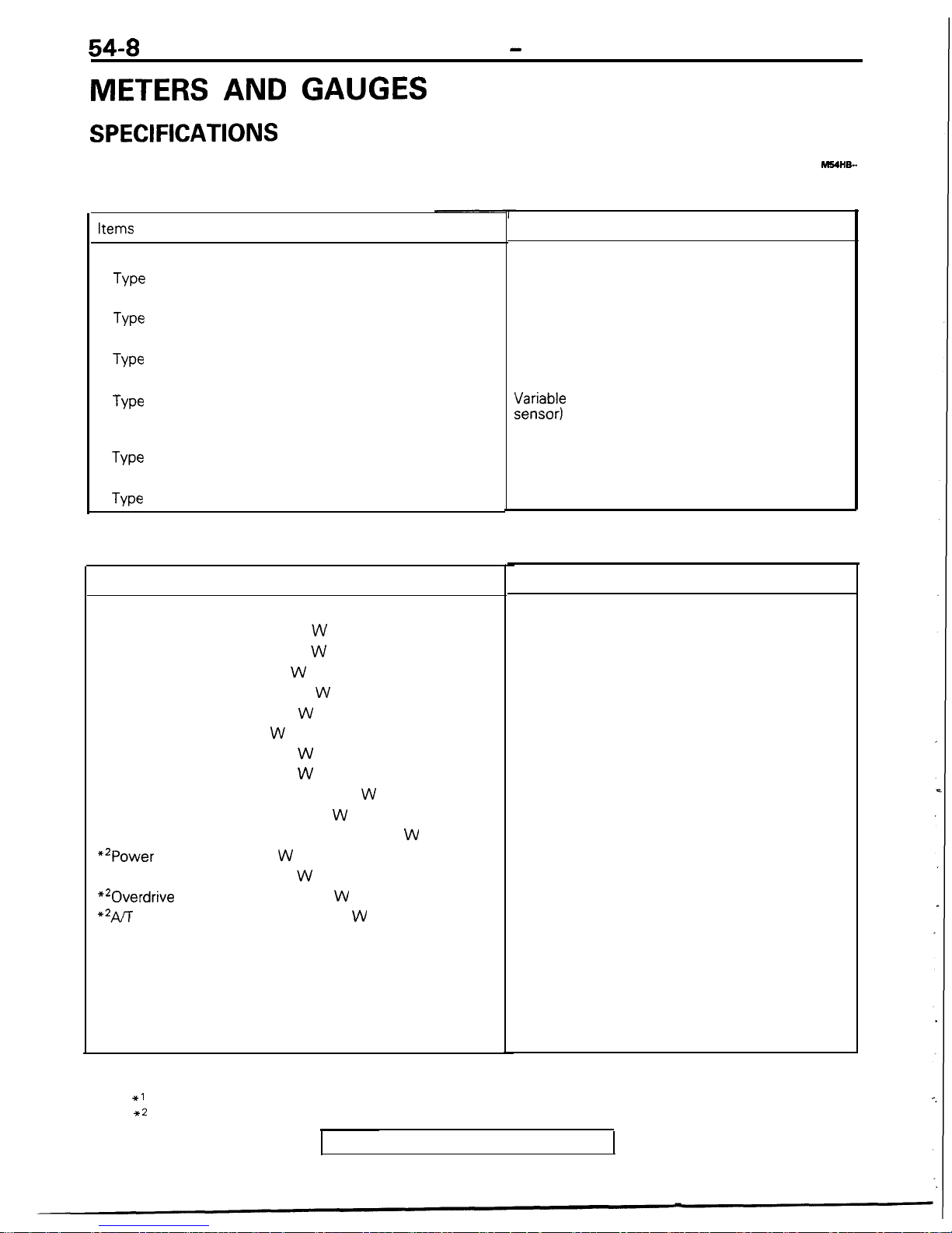
METERS AND GAUGES
SPECIFICATIONS
GENERAL SPECIFICATIONS
Meters and Gauges
Items
Speedometer
Type
Tachometer
Type
Fuel gauge
Type
Fuel gauge unit
Type
Engine coolant temperature gauge
Type
Engine coolant temperature gauge unit
Type
Indicators and Warning Lights
Items
Indicator lights
Turn signal indicator light
W
High beam indicator light
W
Charging warning light
W
Oil pressure warning light
W
Door ajar indicator light
W
Brake warning light
W
Fuel level warning light
W
Seat belt indicator light
W
Auto-cruise control indicator light
W
*‘Anti-lock brake warning light
W
Check engine/malfunction indicator lamp
*‘Power indicator light
W
**Economy indicator light
W
*20verdrive
OFF indicator light
W
**AA
shift position indicator light
W
Park
Reverse
Neutral
Drive
Second
Low
W
NOTE
1. The values in parentheses denote SAE trade numbers.
2. The *l symbol indicates vehicles with anti-lock braking system.
3. The ** symbol indicates vehicles with AA.
hl54HQ-
Specifications
Rotary magnet type
Pulse type
Cross coil type fixed needle gauge
;;;:&I;)
resistance type (with fuel level warning
Cross coil type
Thermistor type
Specifications
3.4
(158)
3.4
(158)
1.4
(74)
1.4
(74)
1.4 (74)
1.4
(74)
3.4
(158)
1.4 (74)
1.4
(74)
1.4
(74)
1.4
(74)
1.4
(74)
1.4
(74)
1.4 (74)
1.4
(74)
1.4
(74)
1.4 (74)
1.4
(74)
1.4
(74)
1.4 (74)
TSB Revision
METERS AND GAUGES - Specifications
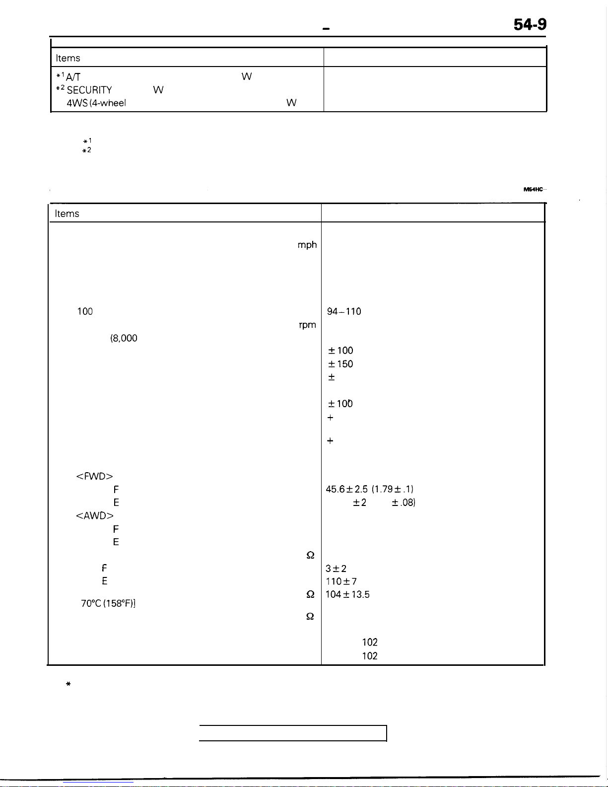
Items
Specifications
*’ A/T
fluid temperature warning light
W
1.4 (74)
**SECURITY
light
W
1.4 (74)
4WS (4-wheel
steering system) warning light
W
1.4 (74)
54-9
NOTE
1. The value in parentheses denote SAE trade numbers
2. The *1 symbol indicates AWD-AK.
3. The ** symbol indicates vehicles with theft-alarm system.
SERVICE SPECIFICATIONS
Items
Specifications
Standard value
Speedometer indication error
mph
20
19-22
40
38-44
60
57-66
80
76-88
100
94-l 10
Tachometer indication error
wm
Type 1
(8,000
rpm indication)
700
?I00
3,000
+150
6,000
+
300
Type 2 (9,000 rpm indication)*
700
+100
3,000 + 225
-100
7,000 + 400
-100
Operation range of fuel gauge unit
mm (in.)
<FWD>
Point
F
45.6k2.5 (1.79k.l)
Point
E
177.5 +2 (6.98 2.08)
<AWD>
Point
F
43 (1.69)
Point
E
174 (6.85)
Fuel gauge unit resistance
52
Point
F
3f2
Point
E
110+7
Engine coolant temperature gauge unit resistance
n
104+13.5
[at
70°C (158”F)l
Fuel gauge resistance
52
Between A-B
Approx. 203
Between A-C
Approx.
102
Between B-C
Approx.
102
NOTE
The * symbol indicates DOHC models.
TSB Revision
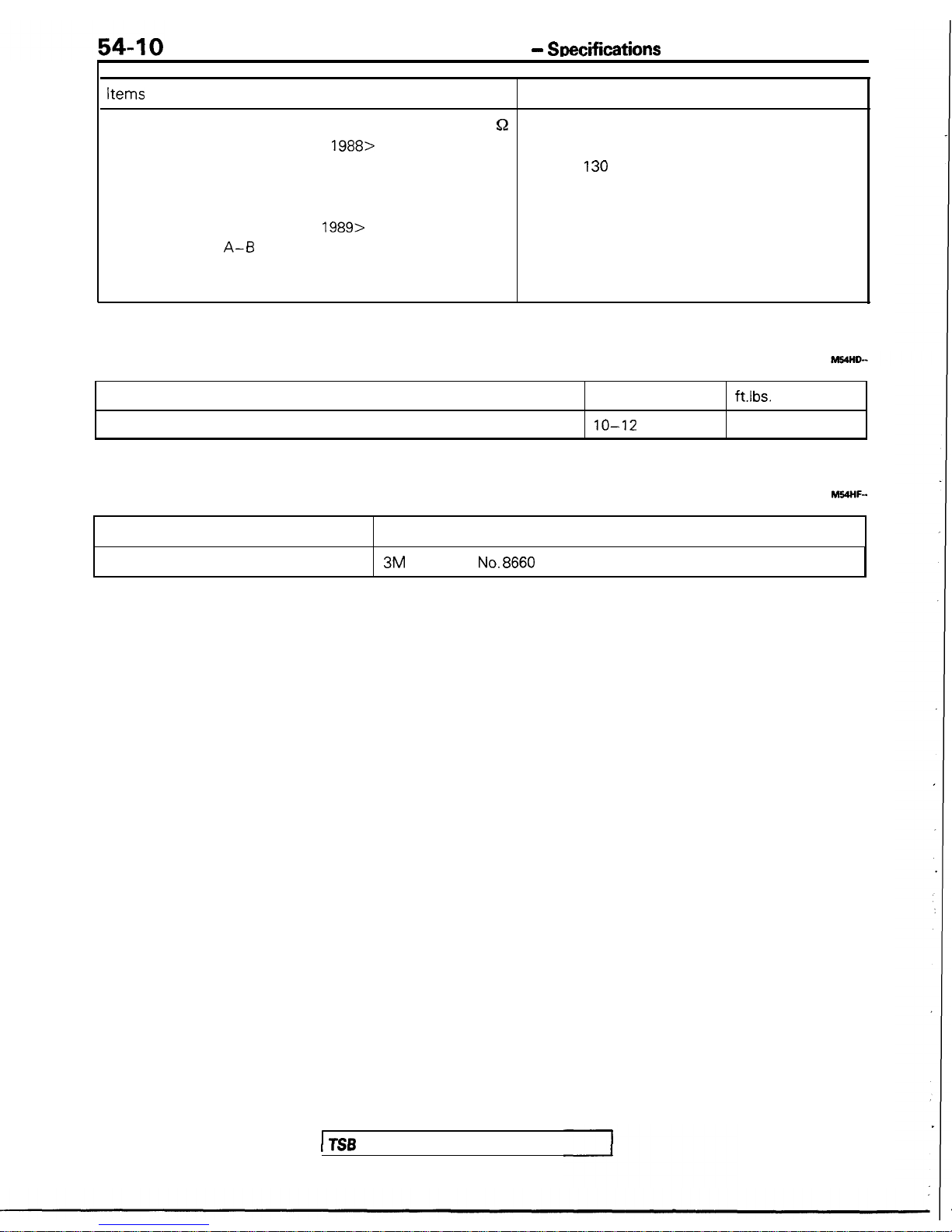
METERS AND GAUGES -
Suecifications
Items
Engine coolant temperature gauge resistance
<Vehicles built up to Dec.
1988>
Between A-B
Between A-C
Between B-C
<Vehicles built from Jan.
1989>
Between
A-0
Between A-C
Between B-C
Specifications
Q
Approx.
130
Approx. 53
Approx. 162
Approx. 146
Approx. 60
Approx. 206
TORQUE SPECIFICATIONS
Items
Engine coolant temperature gauge unit
Nm
10-12
ft.lbs.
7-8
SEALANTS AND ADHESIVES
M54HF-
Items Specified sealant and Adhesive
Engine coolant temperature gauge unit 3M ATD Part
No.8660
or equivalent
I TSB
Revision
54-P 1
NOTES

54-12
METERS AND GAUGES - Troubleshooting
TROUBLESHOOTING
M54HHAQb
<Up to 1990 models>
J/B
z8
c-37
1
:
t
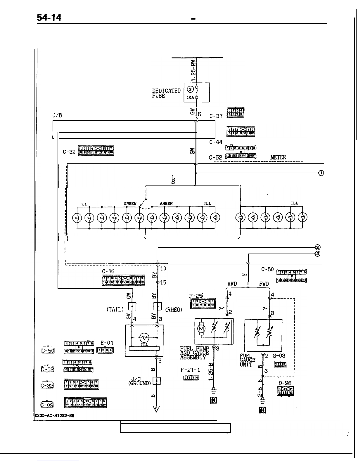
METER AND GAUGES CIRCUIT
CIRCUIT DIAGRAM
TAILLIGHT RELAY
31
__--__-____---___---~~---~~-----~-~---~~
---__--___---_-_----~~--~~~--~~~~-~~~~~-
WITH
WITHOUT
METER COLOR
METER COLOR
CHANGER SWITCH
CHANGER SWITCH
r
I
METER COLOR
CHANGER SWITCH
\I
\/
_--_-_--___--___--~~~--
__--________________________
10
Ti6 C-50
ii2
>
3515
,AWD
,
FWD,
J/C
(TAIL)
RHEOSTAT
E-01
m
J/C
(RHEO)
J/C
(GROUND)
P
m
F-21-1 i
pmq
;
4
------
1
I
>
I
I
,3
I
,C
I
I
I
I
I
I
I
I
I
I
I
I
FUEL
r'$2 G-03 j
8KE
m3 m
j
I
------e-J
D-26
35-AC-Hl014-NY
TSB Revision

r
@
IOA
IGNITION
SWITCH(IG1)
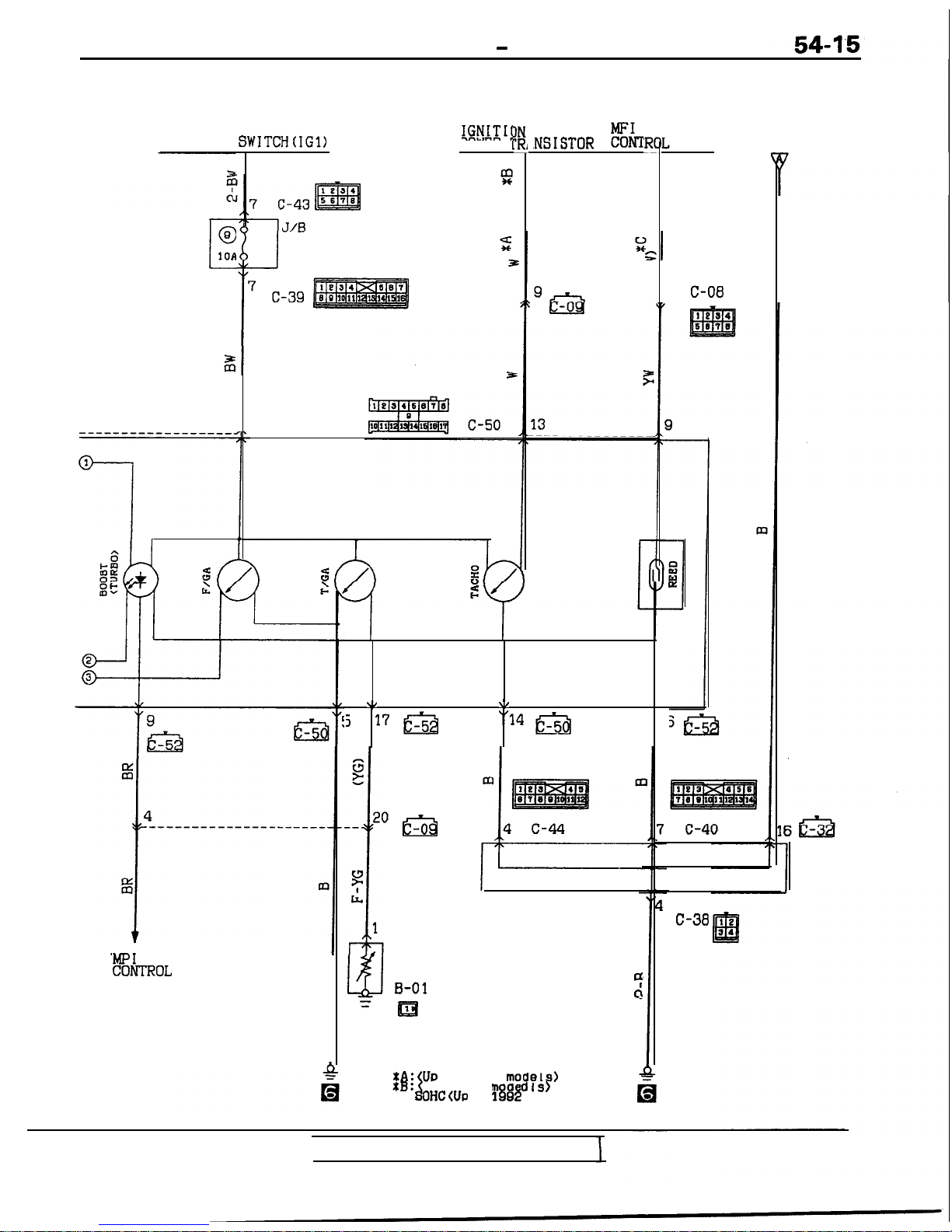
METERS AND GAUGES - Troubleshooting
54-13
COIL
)ELS>
IN
;;;.;>STOR MFI
CONTROL UNIT
RHEOSTAT
I--
2
POWER
T
Cl990 M
1234
Ell
7
c-43 56'8
1
J/B
3
0
-------------_-_-------------.
3
c-00
$C
1234
m
5678
z
13
t
3
-------------
a.
1C
TEMPERATURE
GAUGE UNIT
u B-01
=
p=J
m
cl
1
TSB
Revision
1
METER AND GAUGES CIRCUIT
CIRCUIT DIAGRAM
<from 1991 models>
TAILLIGHT RELAY
J/B
%6
\
c-37
,\
I
54-14
METERS AND GAUGES - Troubleshooting
L
3
"5
c-44
c-32
3
COMBINATION
11
c-52
METER
I;-
-----------_-___-----------------------,
-___-----------_-----------------
-------
m
WITH
0
METER CO
k
OR
WITHOUT METER COLOR
@
CHANGER
WITCH
*
CHANGER SWITCH
I
1
I
I
METER COLOR
I
CHANGER SWITCH
I
I
I
I
I
I
I
I
I
!
I
\
I
I
I
I
@
I
I
I
@
I
\I
“16
C-50
>
F-----z
AWD
F-25
J/C
J/C
(TAIL)
(RHEO)
s
RHEOSTAT
E-01
@=T&
r-1
D-26
TSB Revision
METERS AND GAUGES - Troubleshooting
IGNITION SWITCH(IG1)
@
L
10A
8
IGNITIJ
POWER
m
,c
!%TROL
UNIT
.NSISTOR
%lJ
.b
\I
j 17m
“14 m
m
J/B
ENGINE
COOLANT
TEMPERATURE
GAUGE UNIT
B-01
4
cl
El
Remarks
tA: (UP
to 1992
models)
%B:
XC:
ii
From 1993 m d
Is)
OHCWP
to
1898
models)
UNIT
3
C-08
RHEOSTAT
C-38
TSB Revision
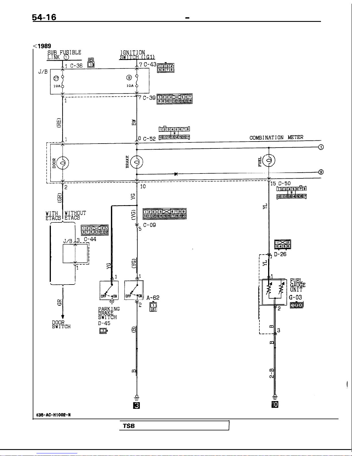
54-16
METERS AND GAUGES - Troubleshooting
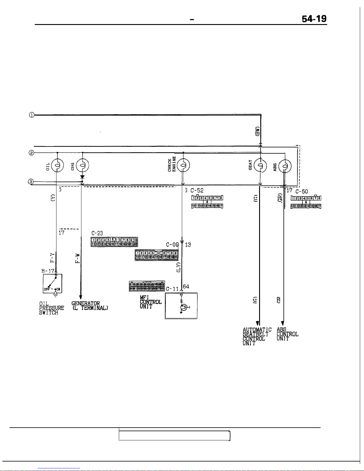
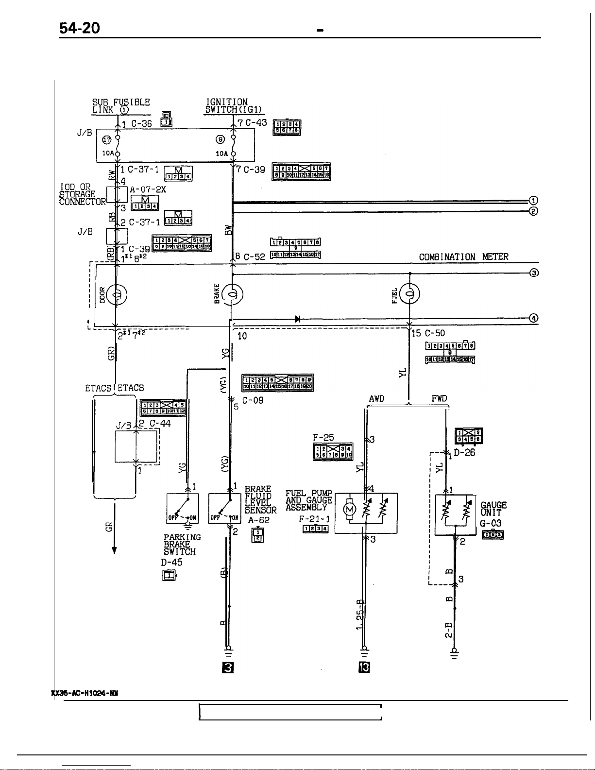
WARNING LIGHT CIRCUIT
CIRCUIT DIAGRAM
<
:1989
models>
KM-AC-HlOOZ-N
BRAKE
FLUID
LEVEL
SENSOR
A-62
1
G-03
@Jg
TSB
Revision
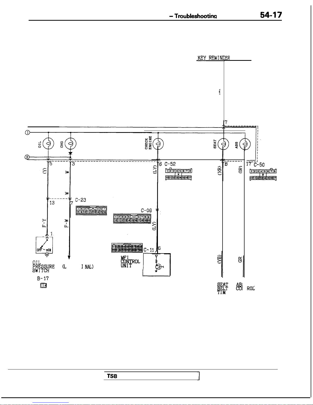
METERS AND GAUGES -
Troubleshootinn
54-17
-KEY REMI.
i
B-17
Es
GENERATOR
(L
TERM I
NAL
J
C-l
MFI
tEFoL
r
; C-52
5
TSB
Revision
13
4
B
T
1ER
SWITCH
------s
g
T ABI
co1
ER UN
17 c-50
ROS,
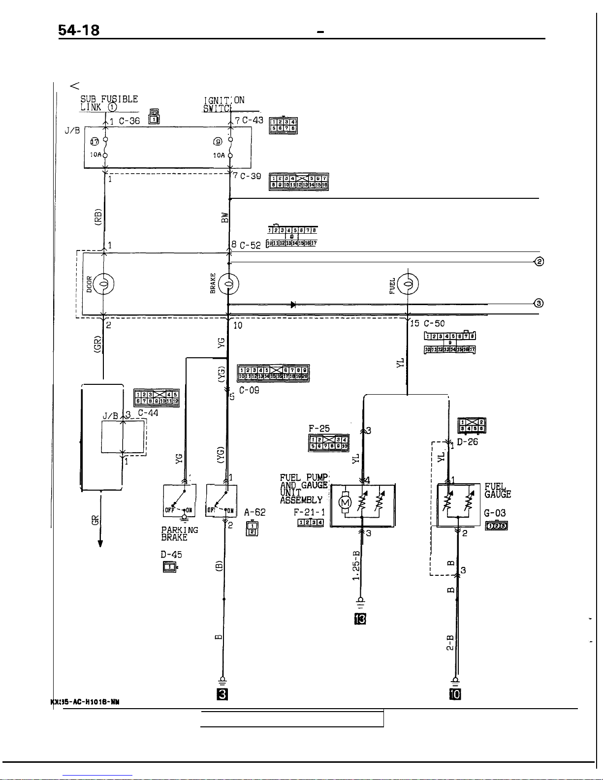
METERS AND GAUGES - Troubleshootina
WARNING LIGHT CIRCUIT
CIRCUIT DIAGRAM
<
1990 models>
WITH WITHOUT
ETACS ETACS
L
OFI
I
I
lr
ixifi””
SWITCH
DOOR
SWITCH
D-45
m
:ON
1
n
~IP~314~5~6J7~2
SC-52 G
I 2 1
1ul13~12~12~14~1~1~17
COMBINATION METER
~
c-09
AWD
.
FWD
r
,
BRAKE
FLUID
LEVEL
SENSOR
A-62
XkE
UNIT
G-03
@Q
3%AC-HlOlB-NY
TSB Revision
METERS AND GAUGES - Troubleshootina
54-19
@------
E
=-----3
3
3
.-----,T)
II
-----------------------------.
3
0
C-23
3 C-52
g
7
-----------
i-1
(I big
.------
3
g
%
[ROL
TSB Revision
54-20
METERS AND GAUGES - Troubleshooting
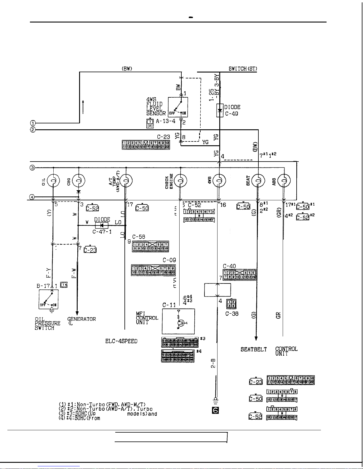
WARNING LIGHT CIRCUIT
CIRCUIT DIAGRAM
I
E
C
<From 1991 models>
‘1
1
I
I
I
L---$-------------
-------
tp¶pZ
WITH WITHOUT
I-
z
ETACS*ETAFS
t
DOOR
SWITCH
D-45
ml
D-26
I
1
1
TSB Revision
I
,
4
FUEL
mwE
G-03
METERS AND GAUGES - Troubleshooting
54-21
(BW)
IGNITION
SWITCH(ST)
,,
19
-----I
ii
@
@
I
b
%6
I
9
5+----J .fG
i.2
g4
- 7’1
1’2
---------
I\
-----
35
f
1
7553
OIL
GENERATOR
EREfRE
(L
TERMINAL)
C-OS
13
5
c
J/B
7c
,6’4
c
AL
,
d
c-11
,4:3
_---------
3 C-52
7,
I
1
ELC-4SPEED
AUTOMATIC
TRANSAXLE
CONTROL MODULE
AUTOMATIC ABS
SEATBELT
CONTROL
##FROL
UNIT
Remarks
(l)%l:Non-Turbo(FWD,AWD-M/T)
(2)%2:Non-Turbo(AWD-A/T),Turbo
(~)Z~:SOHC(UP
to 1992
models)and
DOHC
(4):4:SOHC(From
1993 models)
TSB
Revision
54-22
METERS AND GAUGES - Troubleshooting
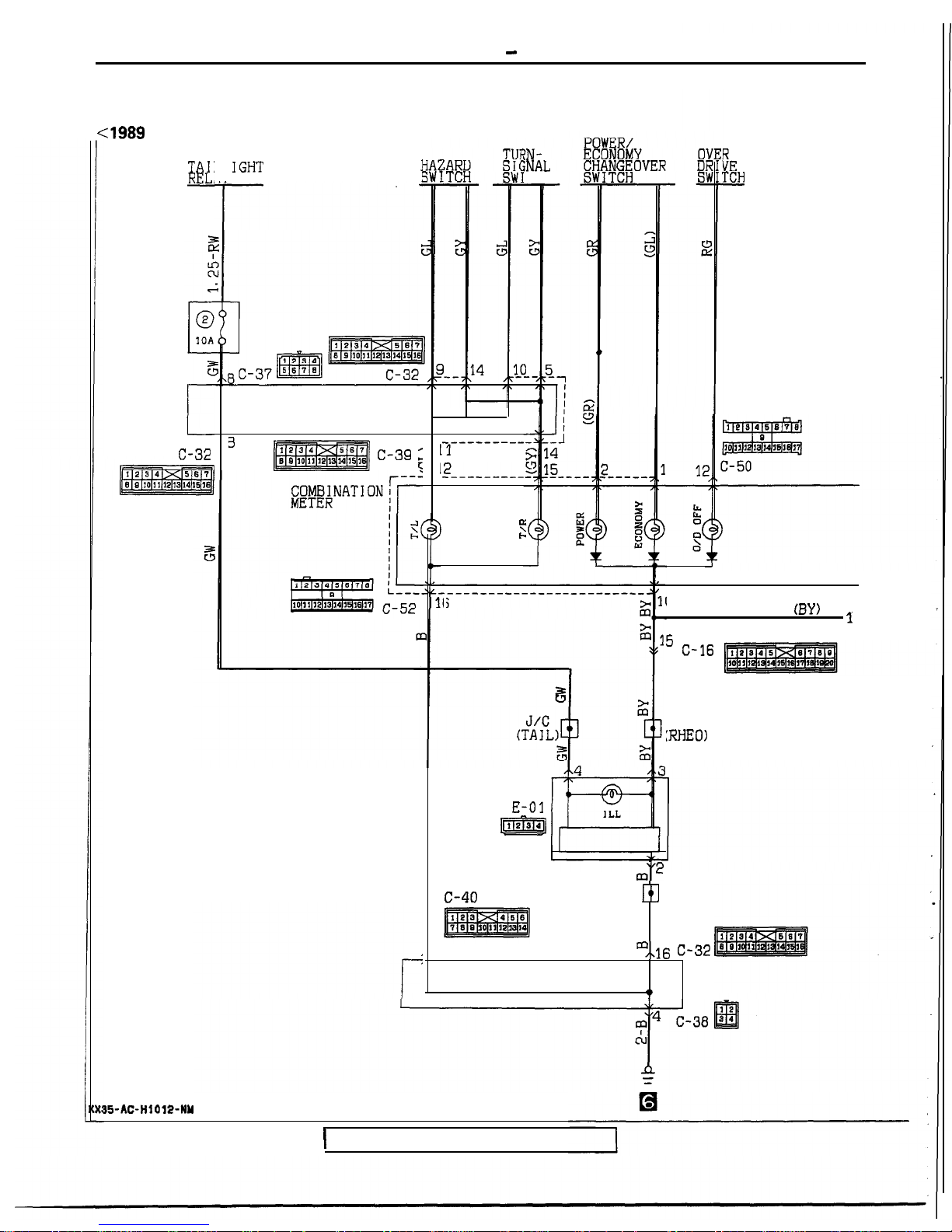
INDICATOR LIGHT CIRCUIT
CIRCUIT DIAGRAM
cl989
models>
FE
TCH
-
ZN;NAL
TCH
TAI:
REL,
IGHT
1
DEDICATED
FUSE
J/B
r
I
C-32
3
p!$Tzaq c-39 ;
_------_--
I1
‘2--------
I
e
L-
6
3
(BY) l
5 C-16
J/C
:RHEO)
m’2
c-40
J/C
~3
(GROUND)
,
m/,16 C-32
J/B
t
RHEOSTAT
E-01
m
15-AC-H1012-NY
1
TSB Revision
METERS AND GAUGES - Troubleshooting
54-23
lEUTRAL
ON SWITCH
z
i
2
;
5
-15 .
.___ ---.
3
al
E
I
9
--- ----
a
I
J/B
c-39
IGNITION
SWITCH(IG1)
,i
77
1
>
I
'i
7
.---
C-58
1 c-51
pil%Iq
&&E
3
CONTROL-
ACTUATOR
?
I
6
55
C-23
.___----------
_------
-I
l4 C-52
COLUMN SWITCH
(#t#$PASSING
AUTO-CRUISE
CONTROL UNIT
TSB Revision
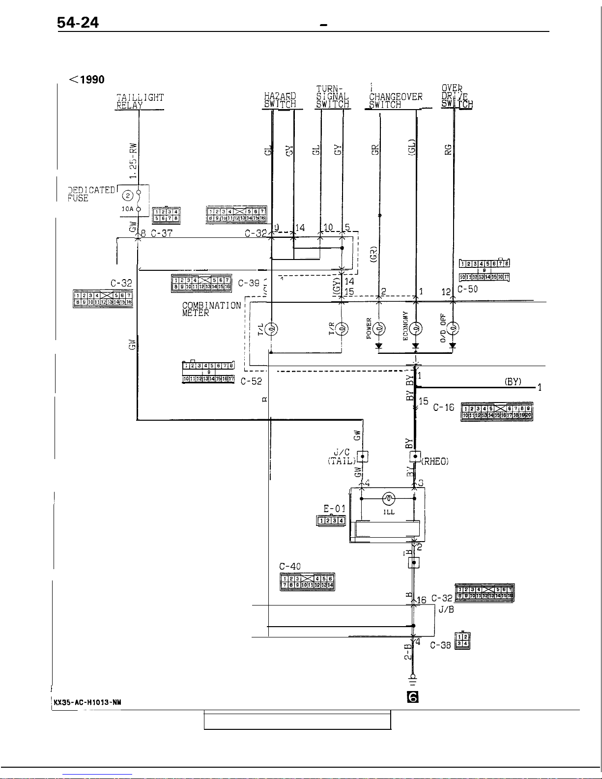
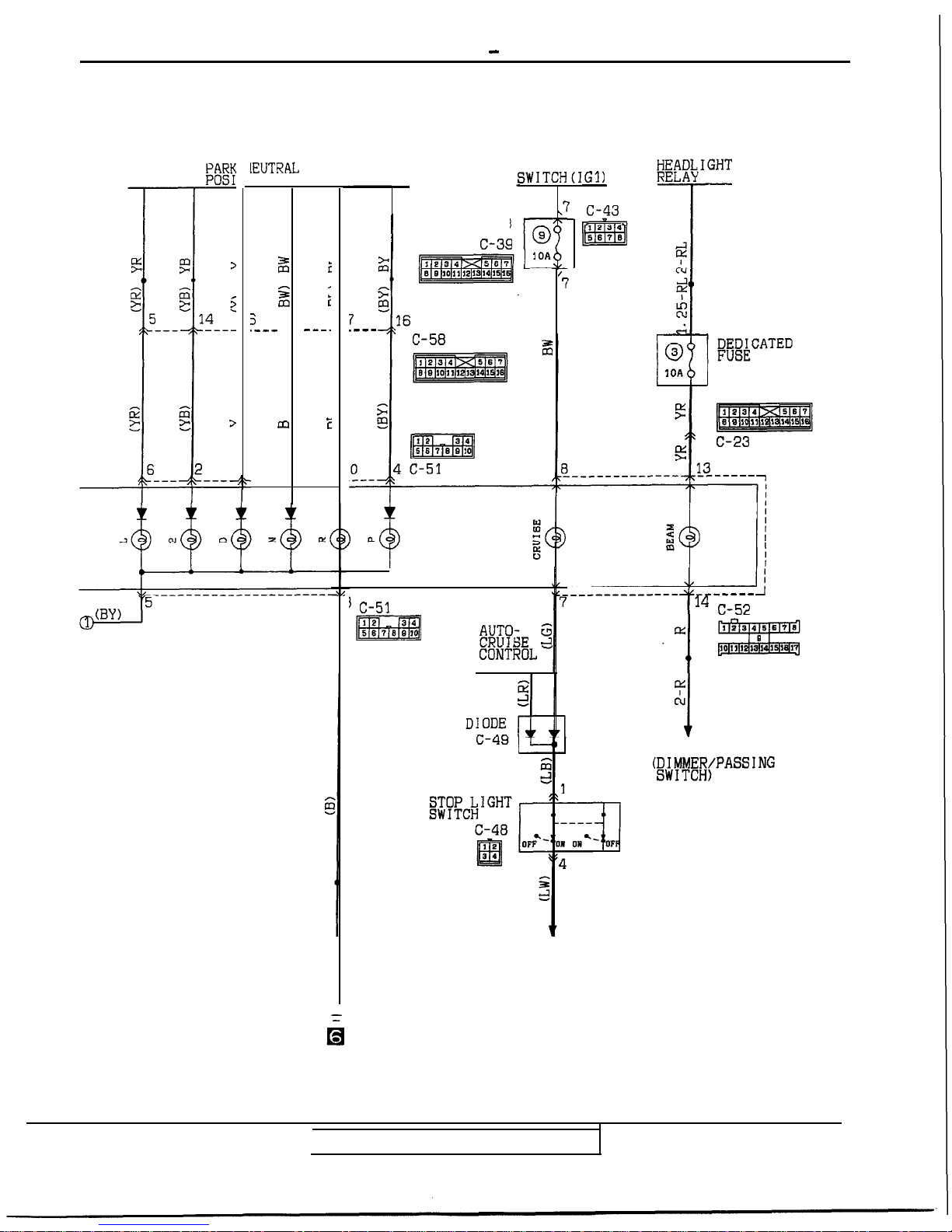
54-24
METERS AND GAUGES - Troubleshooting
INDICATOR LIGHT CIRCUIT
CIRCUIT DIAGRAM
< 1990
models>
POWER/
ECONOMY
iZ(jf'E;OVER
I
3c
TCH
-
YE
-
5
I
--
r
u
r ?:
0 C-37
C-32
J/B
I
I
,
-- .-
-
I---------
*
0
C-32
p7zmsJq
2
----------
____---_-_-_--_____-----.
6
0
(BY) 1
J/C
(RHEOj
RHEOSTAT
E-01
pF5i-q
J/C
'
(GROUND)
c-40
pRiz$mq
I
\KX35-AC-HlOY3-NY
TSB Revision
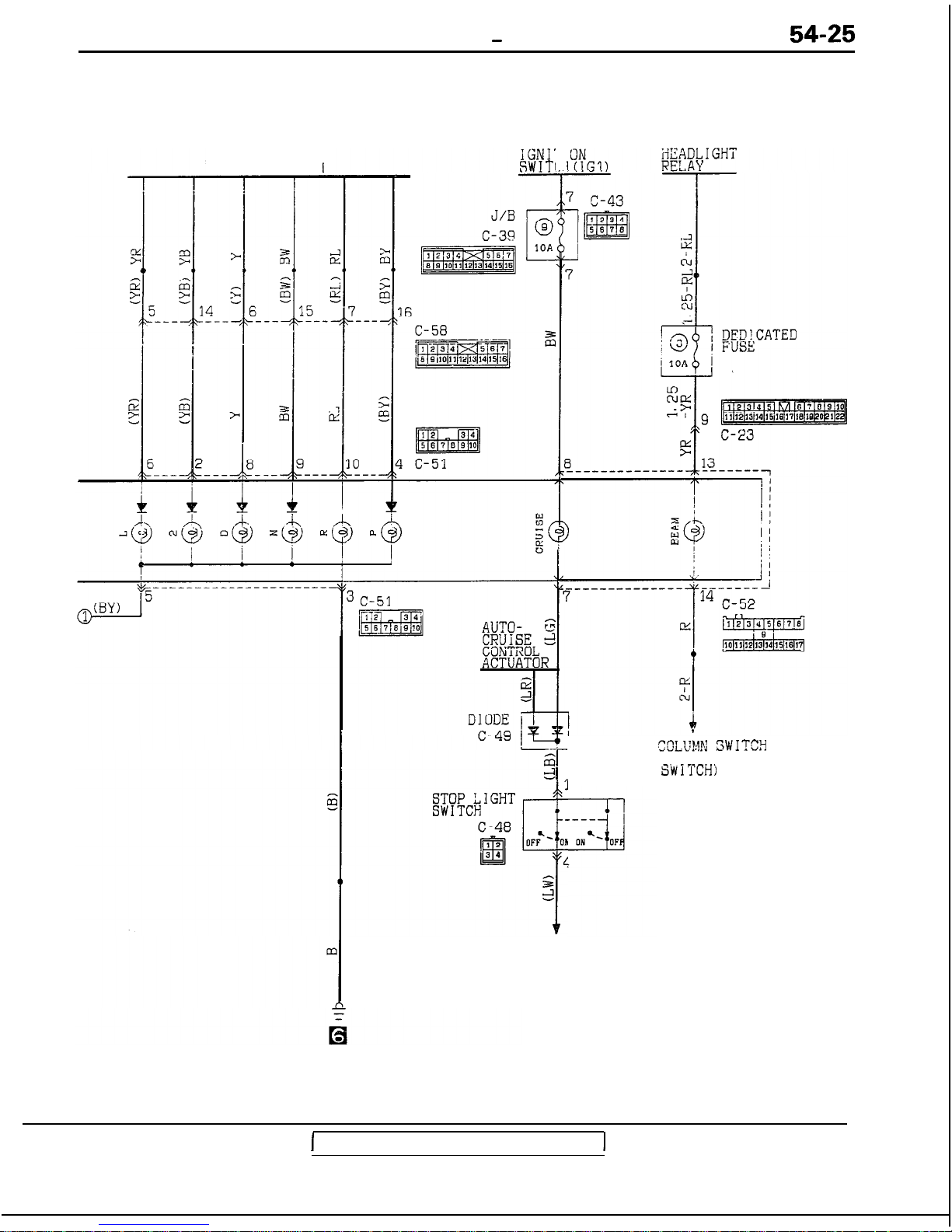
METERS AND GAUGES - Troubleshooting
54-25
PARK/NEUTRAL
POSITION SWITCH
IGNI'
SWITl
I
3
e
Oh
4
i
AUTO-CRUISE
CONTROL UNIT
COLU?J.h:
3WITCH
(DIMMER/PASSING
SWiTCHj
1
TSB Revision
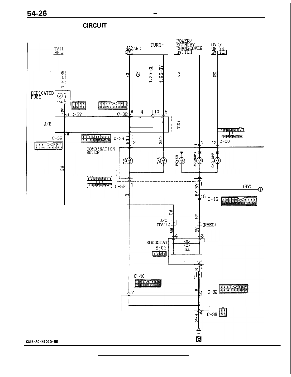
54-26
METERS AND GAUGES - Troubleshooting
INDICATOR LIGHT
CIRCUIT
CIRCUIT DIAGRAM
<From 1991 models>
35-AC-HIOYO-NY
IGHT
f
E
r
TURN-
3
:ARD
TCH
SIGNAL
Ei
SWITCH
_
>
+ +
(3
z
kc
E
.G .s
14
--
,,u?.-,c5
-1
,\ I\ ,\ I
I
<I
,
'
3
f -
::
J
---_-------
--
11
g
14
82
52
15
'__---------
---
---.
3WER/
:ONOMY
jIK!OVER
84;
T-T-
a
)
:----
_----_---------_-~_~~~~~
6
c-40
J/C
(GROUND
I
I
1
'1
:*
k
ZE
I'CH
-
n
1~2~2~4~5~8(7~8
161
l3~llll2ll3ll4llsk6ll
0
(BY) a
.5
C-16
J/C
(RHEO)
6
C-32
1
J/B
TSB Revision
METERS AND GAUGES - Troubleshooting
54-27
PARK/NEUTRAL
POSITION SWITCH
J/B
c-39
5 5 >
z
2
0
p3TzRq
E E
-5 -14
2
2
2
6
-152-7
---
--- --- ___~___
-,l6
c-58
F
I
ETACS
iC#TROL
;NITI
IITCH
\L
I
i
z
,,8_
1.
ON
(IGl)
7 c-43
I
1
I
F&BACATED
~~-----_-_---
-----__
_;
l4 C-52
n
L1?
ll2(3l4~5f6~7~2
I 0
1
16~~1~12~13)1~15(16~17
0
II:
Al
I
COLUMN SWITCH
(&##{PASSING
AUTO-CRUISE
CONTROL UNIT
1
TSB Revision
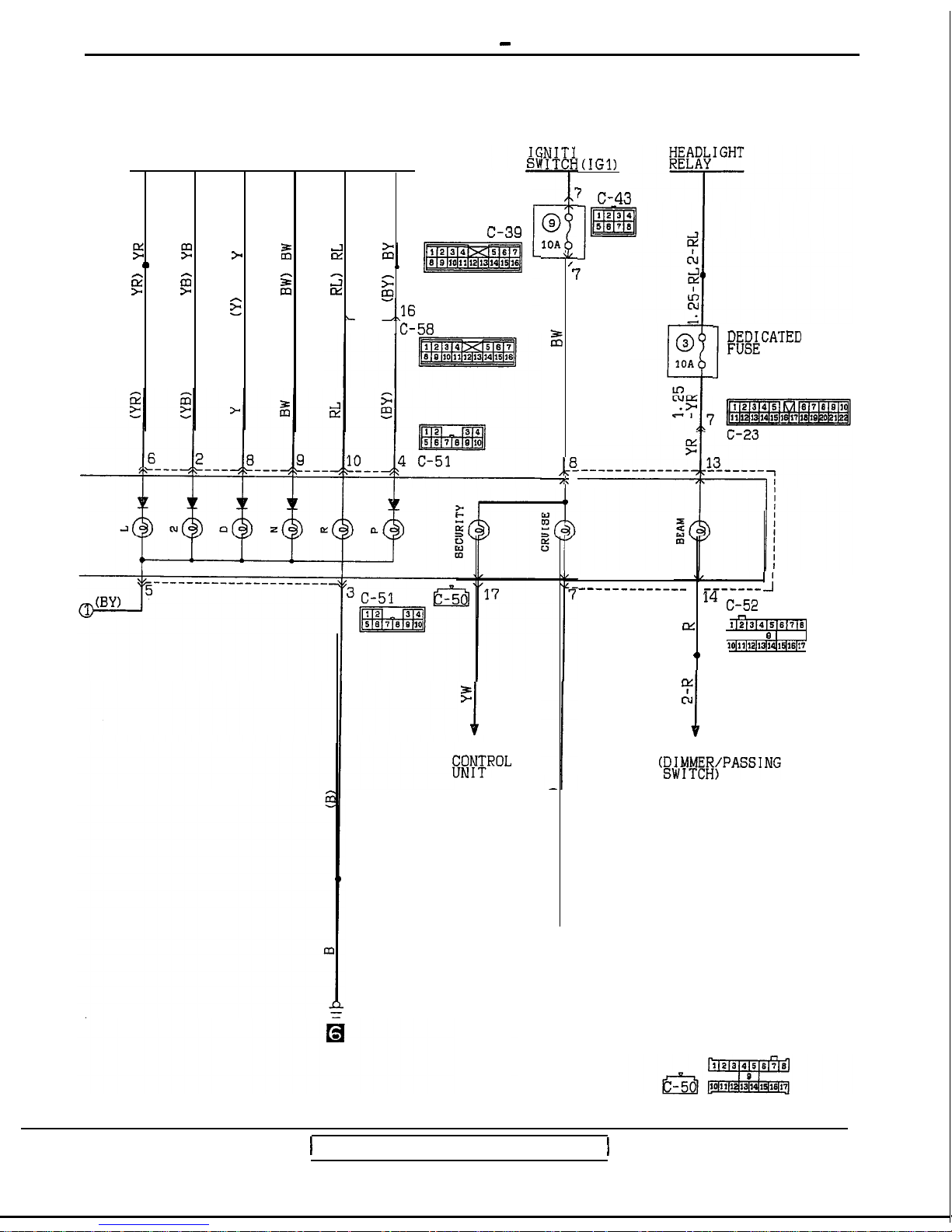
l When the engine coolant temperature is high,
the
unit’s
resistance is low and there is a great
flow of current in the circuit, so the gauge’s
indicator indicates in the “H” area.
l When the engine coolant temperature is low,
the unit’s resistance is high and there is a small
flow of current in the circuit, so the gauge’s
indicator indicates in the “C” area.
<Reed switch>
l Pulses are produced in accordance with the
vehicle speed, and vehicle-speed signals are
input to systems (the transaxle-control system,
etc.) that regulate according to the vehicle
speed.
NOTE
For operation of warning light and indicator light,
refer to
P.54-36.
3. Systems dependent upon control according to
the vehicle speed do not function correctly.
l Check the reed switch (located within the
speedometer).
4. The meter illumination light does not illuminate.
(1)
The tail lights illuminate.
l Check the rheostat.
.
i
TSB Revision
54-28
METERS AND GAUGES
-
Troubleshooting
OPERATION
<Fuel gauge>
l When the ignition key is at the “ON” position,
the fuel gauge is activated.
l
When there is much fuel, the unit’s resistance is
small and the current flowing in the circuit is
great, so the gauge’s indicator indicates in the
“F” area.
l
When there is little fuel, the unit’s resistance is
high and the current flowing in the circuit is
small, so the gauge’s indicator indicates in the
“E” area.
<Engine coolant temperature gauge>
l When the ignition key is at the “ON” position,
the engine coolant temperature gauge is activated.
TROUBLESHOOTING HINTS
1. The fuel gauge doesn’t function, or shows the
incorrect indication.
(1) Disconnect the connector of the fuel gauge
unit; the “F” side is indicated when terminal
3 (FWD) or 2 (AWD) is then grounded.
l Check the fuel gauge.
2. The engine coolant temperature gauge doesn’t
function, or shows the incorrect indication.
(1) The “H” side is indicated when the connec-
tor of the engine coolant temperature gauge
unit is disconnected and then grounded.
l Check the engine coolant temperature
gauge unit.
METERS AND GAUGES - Service Adjustment Procedures
54-29
Drum
stopper
16LO294
Reference value
Il.150 mm (45.3 in.)]
Front
trac
hook
Front
-L
:tion
\
-7
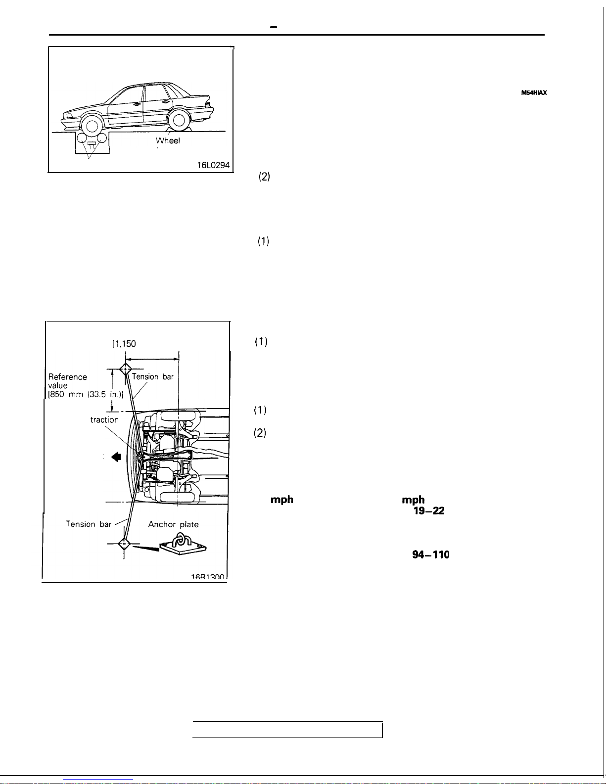
SERVICE ADJUSTMENT PROCEDURES
INSPECTION
SPEEDOMETER INSPECTION
MWIAX
NOTE
For AWD models, refer to the section concerning special
handling instructions for AWD models in GROUP 00.
Take note of the following before inspection:
(1) Assure tire pressure at standard value.
(Refer to GROUP 31 -Specifications.)
(2)
When placing the vehicle on a speedometer tester drum,
make sure the center line of the vehicle is at right angles to
the center line of the drum. Also, make sure the drum is
positioned so as to center between the front tires.
Rear wheel safety procedures
(1)
Be sure to chock both rear wheels to prevent the vehicle
from moving. Secure the stoppers to the floor, or take
measures to prevent the stoppers from slipping.
(2) Make sure the parking brake has been set.
Front wheel away prevention procedure
(1)
Attach tension bars to the front traction hook. Secure the
ends of both bars to anchor plates.
(2) Make sure the tension on the right and left bars is the
same. Also be sure there is enough tension on each bar.
Accident prevention procedures
(1)
Attach a chain or wire to the rear traction hook. Make sure
the end of the wire or chain is secured firmly.
(2)
Take all other necessary precautions.
Use a speedometer tester to measure the speedometer’s
indication error.
Standard value:
Standard indication Allowable range
mph
mph
20
19-22
40
38-44
60
57-66
80
76-88
100
94-110
TSB Revision
METERS AND GAUGES - Service Adjustment Procedures
For female
Din
(insert clip in
side awav from
lock link)
’
For male pin
(insert clip in
lock link
side)0,Lo246
<Other models>
i”
II
Intake manifold
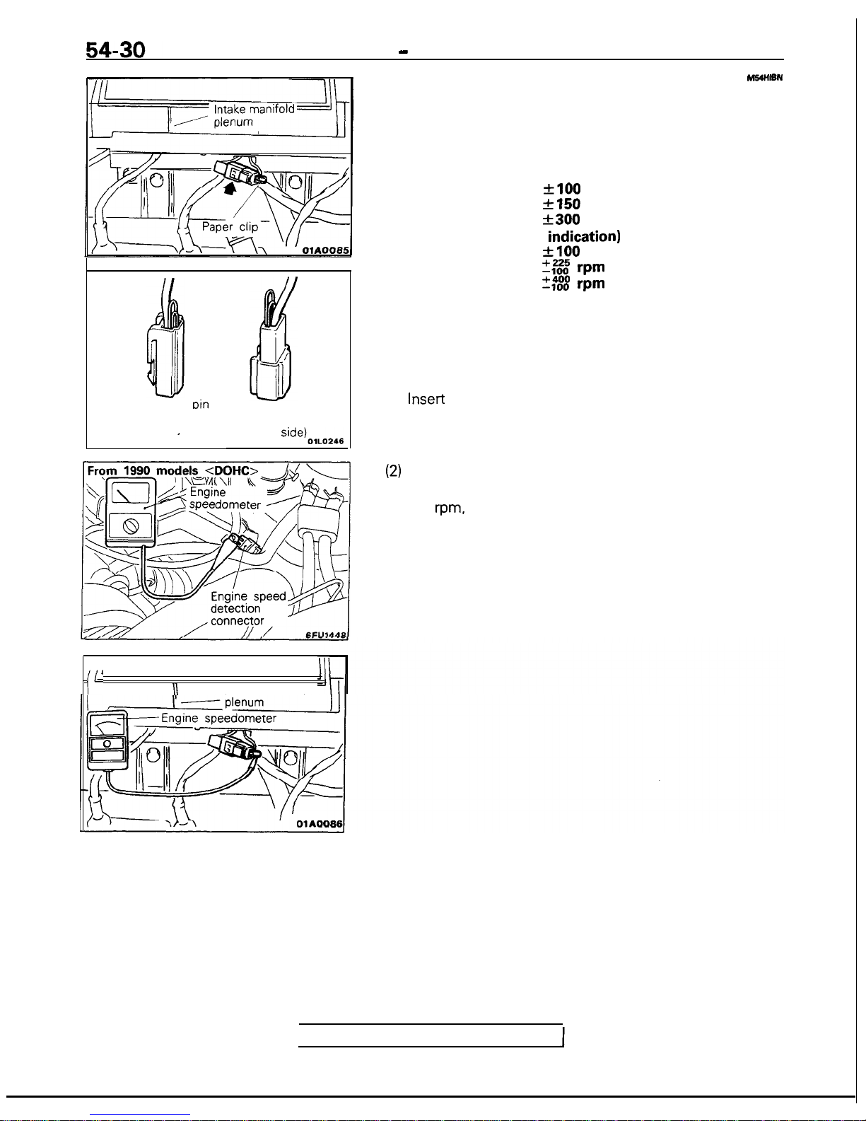
TACHOMETER
INSPECTION
MSUWSN
Connect engine speedometer and compare the engine speedometer and tachometer readings. Replace tachometer if differ-
ence is excessive.
Standard value:
Type 1 (8,000 rpm indication)
700 rpm
flO0
rpm
3,000 rpm
f150
rpm
6,000 rpm
f300
rpm
Type 2 (9,000 rpm
indication)
700 rpm
flO0
rpm
3,000 rpm
7,000 rpm
2; vm
-100
vm
Caution
As the tachometer is negative grounded, do not connect
battery conversely to prevent damaging transistor and
diode.
Connect the engine speedometer.
(1) Insert the paper clip from behind the connector.
Caution
Insert the paper clip parallel to the terminal surface as
shown in the figure at left.
(2)
Connect the engine speedometer to the inserted clip.
NOTE (From 1990 models <DOHC>)
For
rpm.
one-half of the actual engine rpm is indicated, so
the actual engine rpm is two times the indicated value
shown by the tachometer.
TSB Revision
 Loading...