

Page 1

Pub.No.TWDE0911, NOVEMBER 2009
Shop Manual
diesel engine
Page 2

diesel engine
Pub.No.TWDE0911
NOVEMBER 2009
Shop Manual
Page 3

Pub.No.TWDE0911, NOVEMBER 2009
Page 4

GROUP INDEX
FOREWORD
This Shop Manual is published for the information and
guidance of personnel responsible for maintenance of
Mitsubishi Fuso 4M4 series diesel engine, and includes
procedures for adjustment and maintenance services.
We earnestly look forward to seeing that this manual is
made full use of in order to perform correct services with
no wastage.
GENERAL..........................................
ENGINE .............................................
LUBRICATION...................................
FUEL AND ENGINE CONTROL .......
COOLING ..........................................
INTAKE AND EXHAUST ...................
EMISSION CONTROL.......................
HYBRID ELECTRIC VEHICLE
SYSTEM ............................................
00
11
12
13
14
15
17
18
For more details, please consult your nearest authorized
Mitsubishi dealer or distributors.
Kindly note that the specifications and maintenance service figures are subject to change without prior notice in
line with improvement which will be effected from time to
time in the future.
NOVEMBER 2009
Applicable models
4M42T3
©2009 Mitsubishi Fuso Truck & Bus Corporation
Page 5

This Shop Manual contains the information classified into the following groups.
If any system or equipment has two or more variations with significantly different construction, the variations are
handled as different groups. These groups are identified by different alphabets preceded by the same number.
1. ENGINE volume
Group No. Group subject
11 ENGINE
12 LUBRICATION
13 FUEL AND ENGINE CONTROL
14 COOLING
15 INTAKE AND EXHAUST
17 EMISSION CONTROL
18 HYBRID ELECTRIC VEHICLE SYSTEM
2. CHASSIS volume
Group No. Group subject
21 CLUTCH
22 MANUAL TRANSMISSION
22E INOMAT-II
25 PROPELLER SHAFT
26 FRONT AXLE
27 REAR AXLE
31 WHEEL, TIRE
33 FRONT SUSPENSION
34 REAR SUSPENSION
35 BRAKE
35EA POWER ANTI-LOCK BRAKE SYSTEM
35EB HILL START ASSIST SYSTEM
36 PARKING BRAKE
37 STEERING
41 BUMPER, FRAME
42 CAB MOUNTING, TILT
43 DOOR
51 EXTERIOR
52 INTERIOR
55 HEATER, AIR-CONDITIONER
3. ELECTRICAL volume
Group No. Group subject
54 ELECTRICAL
Page 6

GROUP 00 GENERAL
MODIFICATION SUMMARY ............................................................. 00-2
VEHICLE MODEL CODING SYSTEM .............................................. 00-4
EQUIPMENT TYPE CODING SYSTEM ............................................ 00-6
POWER TRAIN TABLE .................................................................... 00-7
HOW TO READ THIS MANUAL ....................................................... 00-8
CHASSIS NUMBER, ENGINE NUMBER, MOTOR NUMBER
AND NAME PLATE ......................................................................... 00-16
PRECAUTIONS FOR MAINTENANCE OPERATION .................... 00-18
JACKING UP THE VEHICLE .......................................................... 00-28
DIAGNOSIS CODES
1. Diagnosis Codes ...................................................................... 00-30
2. Reading and Erasing the Diagnosis Code ................................. 00-31
TABLE OF STANDARD TIGHTENING TORQUES ........................ 00-36
13A
13E
00-1
Page 7

MODIFICATION SUMMARY
1. Characteristics of and Precautions for the ECO HYBRID Model
• The following are added to the characteristics of the CANTER ECO HYBRID.
• The CANTER ECO HYBRID is equipped with a dedicated high voltage battery (350 V) for the hybrid electric ve-
hicle system aside from the 24 V battery.
• High voltage is cut off when the starter switch is OFF and the vehicle is stationary.
• High voltage is generated in the high voltage circuit when the starter switch is ON or when the gear is engaged
and the wheels are rotating.
• High voltage in the high voltage circuit may be generated irrespective of the vehicle condition during the hybrid
electric vehicle system abnormalities (the hybrid electric vehicle warning lamp illuminates).
• Be sure to observe the regulations of your country or region regarding the qualifications or trainings required for
servicing the high-voltage equipment.
• The following are added to the precautions concerning high voltage cable and high voltage devices.
DANGER
• High voltage (350 V) may be generated in the high voltage circuit that consists of various high voltage devices (motor generator, motor electronic control unit and high voltage battery box) and cable (orange). Utmost care is required in handling these parts. When servicing, see Gr18 HYBRID ELECTRIC VEHICLE
SYSTEM.
• Improper use of the high voltage battery may cause electric shock, overheating or fire though it is safe
when properly handled. It may explode in the worst case.
• The following are added to the remedies against vehicle damage by collision or the like.
WARNING
• When the vehicle is on fire, use the ABC fire extinguisher to put out the fire. Since it is dangerous to fight
a fire with a small quantity of water, spray a large amount of water from a fire hydrant or wait for the arrival of the fire brigade.
• When the vehicle is soaked in water, do not touch the high voltage devices and high voltage cable including the safety plug of the high voltage battery box to prevent electric shock. Work on the vehicle after
pulling it out of water.
• Insulate any high voltage terminal that is exposed by damage with vinyl tape or the like to prevent electric
shock.
CAUTION
• The electrolyte in the high voltage battery is as flammable as kerosene. If there is any fluid leakage near
the high voltage box, wipe up the fluid while keeping fire away from it.
• Turn the starter switch to OFF to cut off the high voltage system. If it cannot be confirmed that the starter
switch is OFF, disconnect the negative side battery cable from the 24 V battery. Then, remove the safety
plug of the high voltage battery box with insulated gloves on while referring to Gr18 HYBRID ELECTRIC
VEHICLE SYSTEM.
• In the case of the abnormality described above, replace the defective part referring to Gr18 HYBRID
ELECTRIC VEHICLE SYSTEM.
00-2
Page 8

M E M O
00
00-3
Page 9

VEHICLE MODEL CODING SYSTEM
<For Hong Kong and Singapore>
1 743 52 986
FE84BE
1 Basic vehicle type F Cab-over engine truck
2 Load capacity, drive system E 2 ton class and over, 4 × 2
3 Cab type 8 Wide cab
4 Suspension 4 Independent axle
5 Engine B 4M42T
6 Wheelbase E 3350 mm
7 Chassis arrangement for use V Van use
8 Rear tire arrangement, payload 3
9 Vehicle specification H Hybrid
10 Engine output variation 6 4M42T3 (96 kW {130 PS})
11 Export specification EX
V3H6
11
10
EX
Low deck/rear double
Payload 3000 to 4000 kg
00-4
Page 10

<For Australia and New Zealand>
00
1 743 52 986
FE84BE
1 Basic vehicle type F Cab-over engine truck
2 Load capacity, drive system E 2 ton class and over, 4 × 2
3 Cab type 8 Wide cab
4 Suspension 4 Independent axle
5 Engine B 4M42T
6 Wheelbase E 3350 mm
7 Chassis arrangement for use V Van use
8 Rear tire arrangement, payload 7
9 Steering position R Right-hand drive vehicle
10 Export specification FA
11 Vehicle specification H Hybrid
V7RFA
11
10
H
Rear double
Payload 3000 to 4000 kg
00-5
Page 11
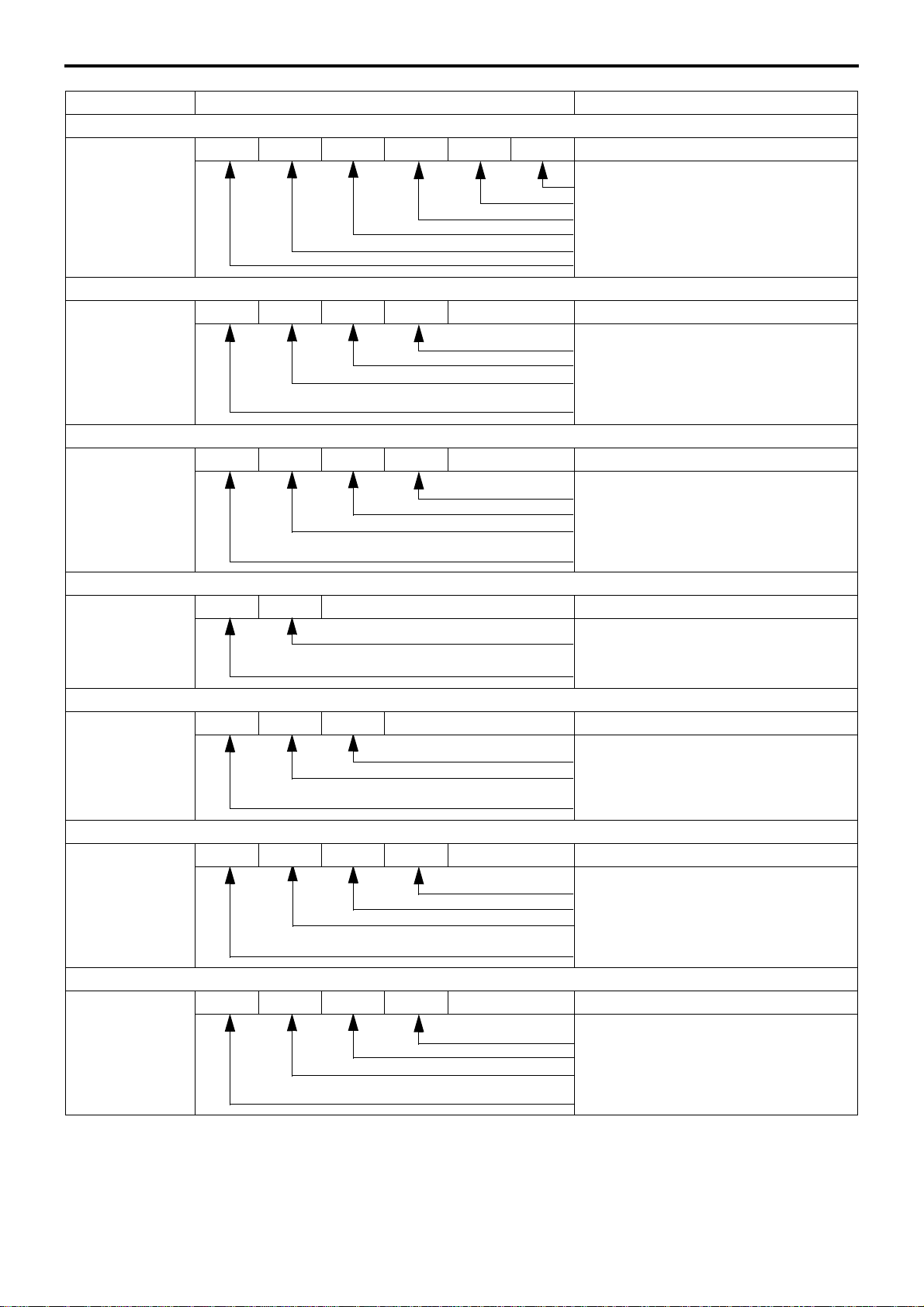
EQUIPMENT TYPE CODING SYSTEM
Component Name plate marking Code description
Engine
4M42T3 4 M 4 2 T 3
Classification of turbocharger
Turbocharged
Order of development within same series
Order of development among different series
Diesel engine
No. of cylinders (4)
Clutch
C3W28 C 3 W 28
Disc outside diameter
Facing material (W: Woven)
Load carrying capacity of truck class (ton nage) on which the clutch is primarily used
Initial letter of the clutch
Transmission
M036S5 M 036 S 5
Forward speeds
Type of mesh (S: Synchromesh)
Load carrying capacity of truck class (ton nage) on which the clutch is primarily used
Initial letter of the transmission
Propeller shaft
P3 P 3
Front axle
F200T F 200 T
Rear axle
R033T R 03 3 T
Reduction and differentioal
D033H D 03 3 H
Load carrying capacity of truck class (ton nage) on which the clutch is primarily used
Initial letter of the propeller shaft
Vehicle type (T: Truck)
Load carrying capacity of truck class (ton nage) on which the clutch is primarily used
Initial letter of the front axle
Vehicle type (T: Truck)
Order of development within same series
Load carrying capacity of truck class (ton nage) on which the clutch is primarily used
Initial letter of the rear axle
Tooth profile (H: Hypoid gear)
Order of development within same series
Load carrying capacity of truck class (ton nage) on which the clutch is primarily used
Initial letter of the reduction & differentioal
00-6
Page 12

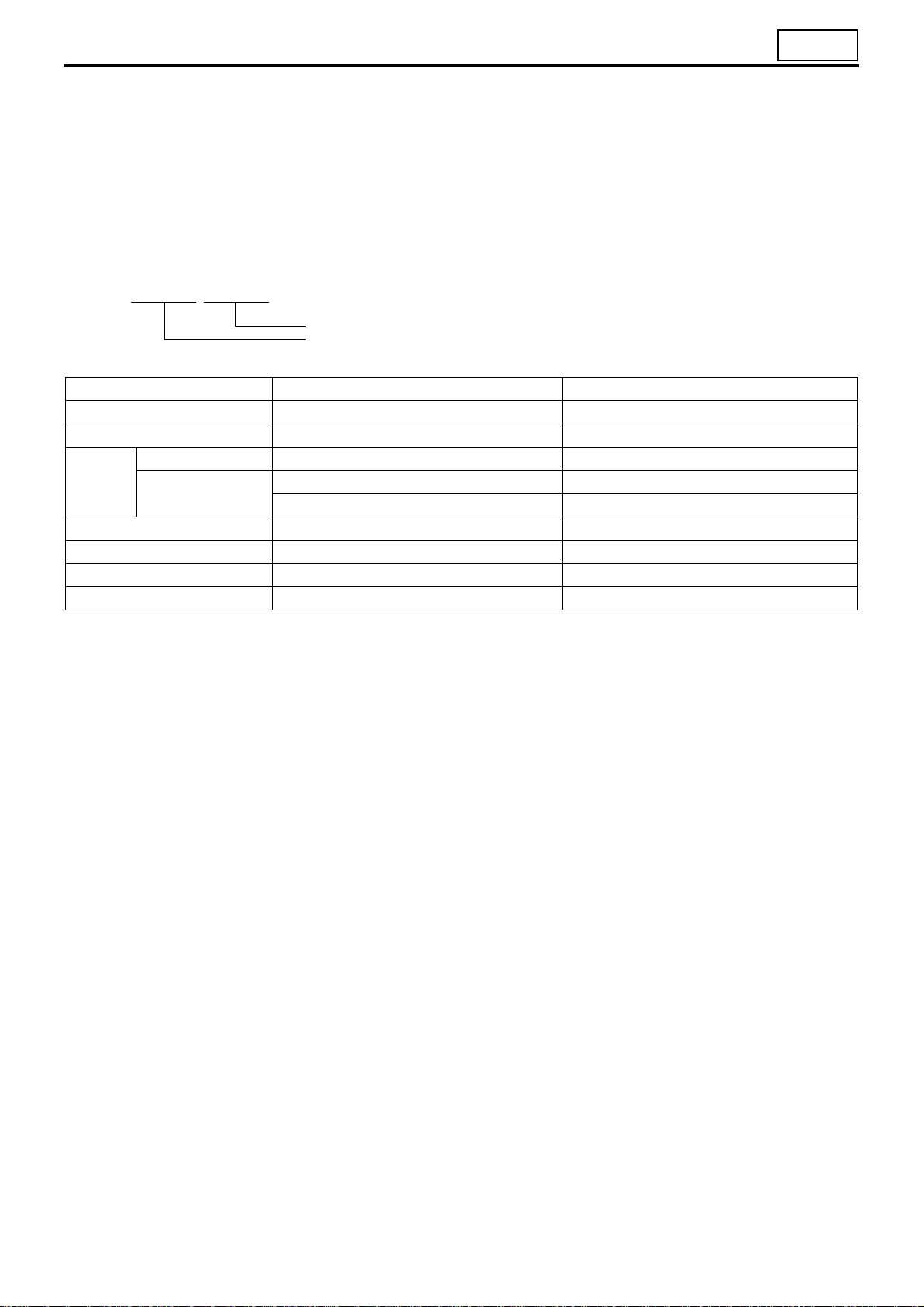
POWER TRAIN TABLE
00
Vehicle model Engine Clutch Transmission Propeller shaft Rear axle
FE84BEV3H6EX 4M42T3 C3W28 M036S5 P3 R033T D033H
FE84BEV7RFAH 4M42T3 C3W28 M036S5 P3 R033T D033H
Reduction and
differential
00-7
Page 13

HOW TO READ THIS MANUAL
This manual consists of the following parts:
• Specifications
• Structure and Operation
• Troubleshooting
• On-vehicle Inspection and Adjustment
• Service procedures
On-vehicle Inspection and Adjustment
• Procedures for inspection and adjustment of individual parts and assemblies as mounted on the vehicle are de-
scribed including specific items to check and adjust. Specified or otherwise, inspection should be performed for
looseness, play, backlash, crack, damage, etc.
Service procedures
• Procedures for servicing components and parts off the vehicle are described centering on key points in their re-
moval, installation, disassembly, reassembly, inspection, etc.
Inspection
• Check items subject to “acceptable/unacceptable” judgement on the basis of service standards are all given.
• Some routine visual checks and cleaning of some reused parts are not described but must always be included in
actual service work.
Caution
• This service manual contains important cautionary instructions and supplementary information under the following
four headings which identify the nature of the instructions and information:
DANGER
WARNING
CAUTION
NOTE
Terms and Units
• Front and rear
The forward running direction of the vehicle is referred to as the front and the reverse running direction is referred
to as the rear.
• Left and right
Left hand side and right hand side, when facing the forward running direction of the vehicle, are respectively left
and right.
Precautions that should be taken in handling potentially dangerous substances
such as battery fluid and coolant additives.
Precautionary instructions, which, if not observed, could result in serious injury or
death.
Precautionary instructions, which, if not observed, could result in damage to or destruction of equipment or parts.
Suggestions or supplementary information for more efficient use of equipment or
better understandings.
Standard value
• Standard value dimensions in designs indicating: the design dimensions of individual parts, the standard clear-
ance between two parts when assembled, and the standard value for an assembly part, as the case may be.
Limit
• When the value of a part exceeds this, it is no longer serviceable in respect of performance and strength and must
be replaced or repaired.
00-8
Page 14
00
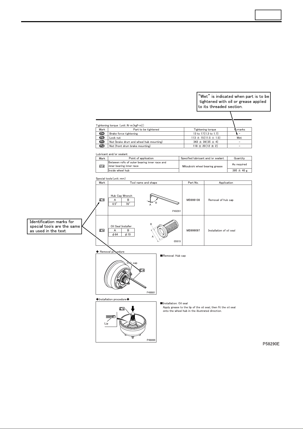
Tightening torque
• Values are directly specified for out-of-standard tightening torques for bolts and nuts.
• Where there is no specified figure for tightening torque, follow the table covering standard tightening torques.
(Values for standard tightening torques are based on thread size and material.)
• When the item is to be tightened in a wet state, “wet” is indicated. Where there is no indication, read it as dry.
Units
• Tightening torques and other parameters are given in SI* units with metric units added in brackets { }.
*SI: Le Système International d’Unités
Example: 390 N·m {40 kgf·m}
Metric unit
SI unit
Item SI unit {metric unit} Conversion factor
Force N {kgf} 9.80665 N {1 kgf}
Moment of force N·m {kgf·m} 9.80665 N·m {1 kgf·m}
Positive pressure kPa {kgf/cm2} 98.0665 kPa {1 kgf/cm2}
Pressure
Volume dm
Heat quantity J {kcal} 4186.05 J {1 kcal}
Heat flow W {kcal/h} 1.16279 W {1 kcal/h}
Power kW {PS} 0.7355 kW {1 PS}
Vacuum pressure
kPa {mmHg} 0.133322 kPa {1 mmHg}
Pa {mmH
O} 9.80665 Pa {1 mmH2O}
2
3
{L} 1 dm3 {1 L}
00-9
Page 15

HOW TO READ THIS MANUAL
1. Illustrated Parts Breakdown and Service Procedures
Symbol Denotation Application Remarks
Tightening torque
Locating pin Parts to be positioned for installation
Non-reusable parts Parts not to be reused
Lubricant and/or
sealant
Special tool
*a Associated part
Parts not tightened to standard torques
(standard torques specified where necessary for servicing)
Parts to be coated with lubricant or sealant
for assembly or installation
Parts for which special tools are required for
service operation
Parts associated with those removed/disassembled for servicing
Specified values shown in table
See Table of Standard Tightening Torques for
parts for which no tightening torques are specified.
Necessary lubricant and/or sealant, quantity required, etc. are specified in table.
Tool name/shape and part number are shown in
table.
00-10
Page 16
00
00-11
Page 17
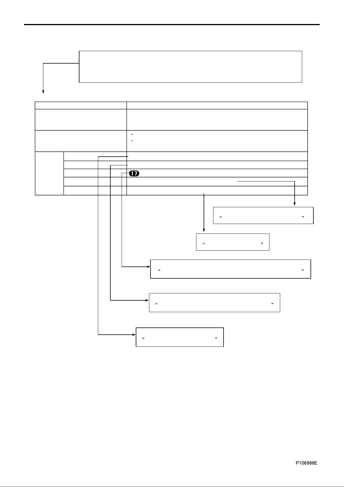
HOW TO READ THIS MANUAL
2. How to Use Diagnosis Codes <Electronic Control System>
There are the diagnosis code and message displayed on Multi-Use Tester.
Numerical values in parenthesis are added only when a diagnostic code indicated in
the Multi-Use Tester display differs from the code indicated by the number of warning
lamp flashes.
P0475: Exhaust Brake PWR (Open) (warning lamp flashes: 93)
Generation condition Exhaust shutter 3-Way magnetic valve circuit is open
System recovers if any valid signal is input when starter switch is turned
Recoverability
Control effected by electronic control
unit
Service data C2: Auxiliary brake M/V1
Actuator test AA: Auxiliary brake M/V1
Inspection
Electronic control unit : Exhaust shutter 3-Way magnetic valve
Electrical equipment #565: Exhaust shutter 3-Way magnetic valve
Electric circuit diagram Exhaust shutter 3-Way magnetic valve circuit
from OFF to ON (the warning lamp does not extinguish unless 3 consecutive
valid signals are input).
Control of auxiliary brake function is deactivated.
White smoke reduction control is deactivated if idling condition is held
for an extended period of time.
Refer to
Refer to
Inspections Performed At Electronic Control Unit Connectors.
Refer to
Actuator Tests Performed Using Multi-Use Tester.
Refer to
Multi-Use Tester Service Data.
Refer to
Inspection of Electrical Equipment.
Electric Circuit Diagram.
00-12
Page 18
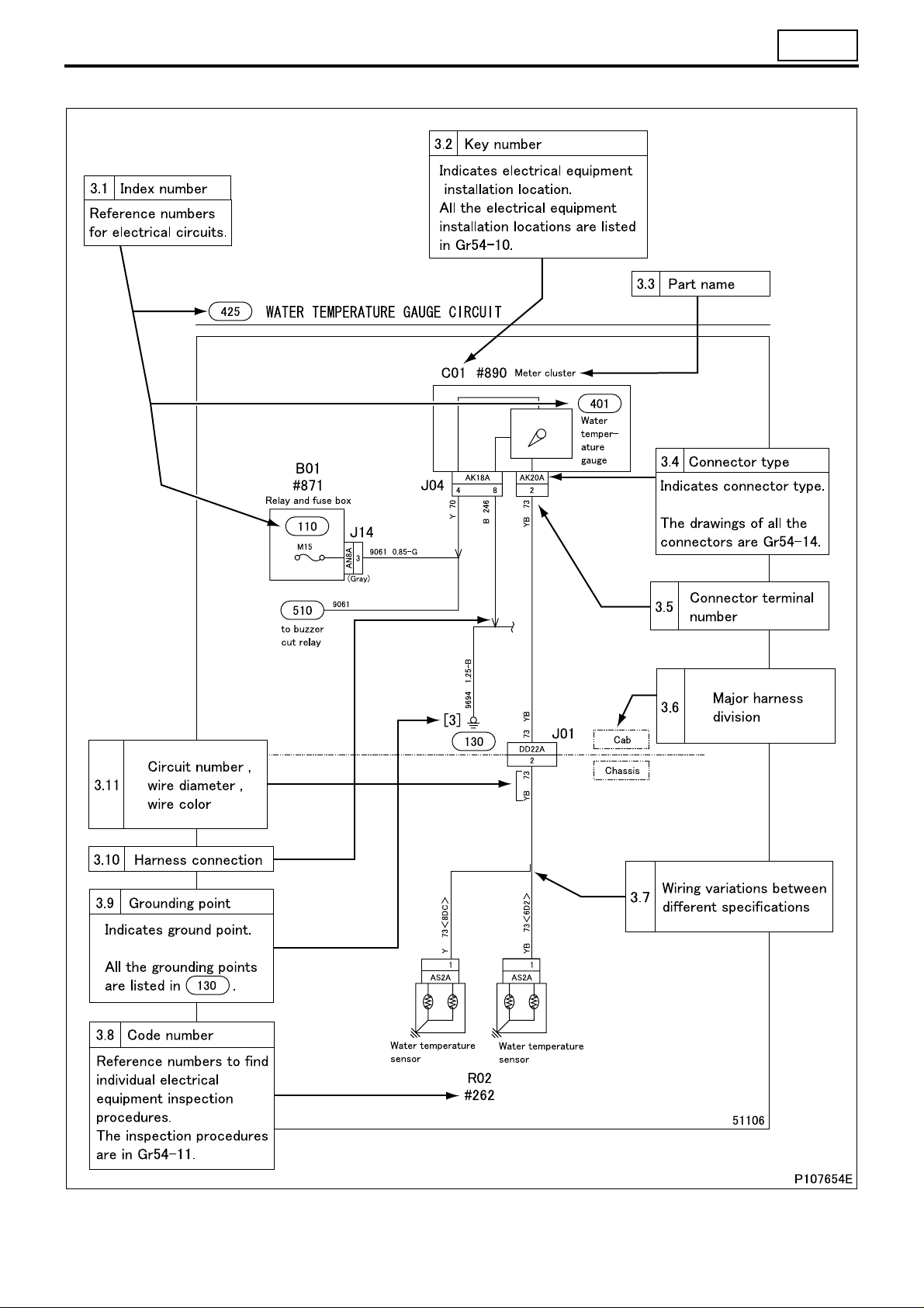
3. How to Read Circuits
00
00-13
Page 19
HOW TO READ THIS MANUAL
3.1 Index number: to
• Index numbers are used as reference numbers for electrical circuits. Each electrical circuit has been assigned its
own index number.
100 999
3.2 Key number: A01 to Z99
• Key numbers indicate electrical equipment installation locations. The installation location of a part can be easily
found using its key number shown in a circuit diagram.
All of the electrical equipment installation locations are listed in Gr54-10.
3.3 Part name
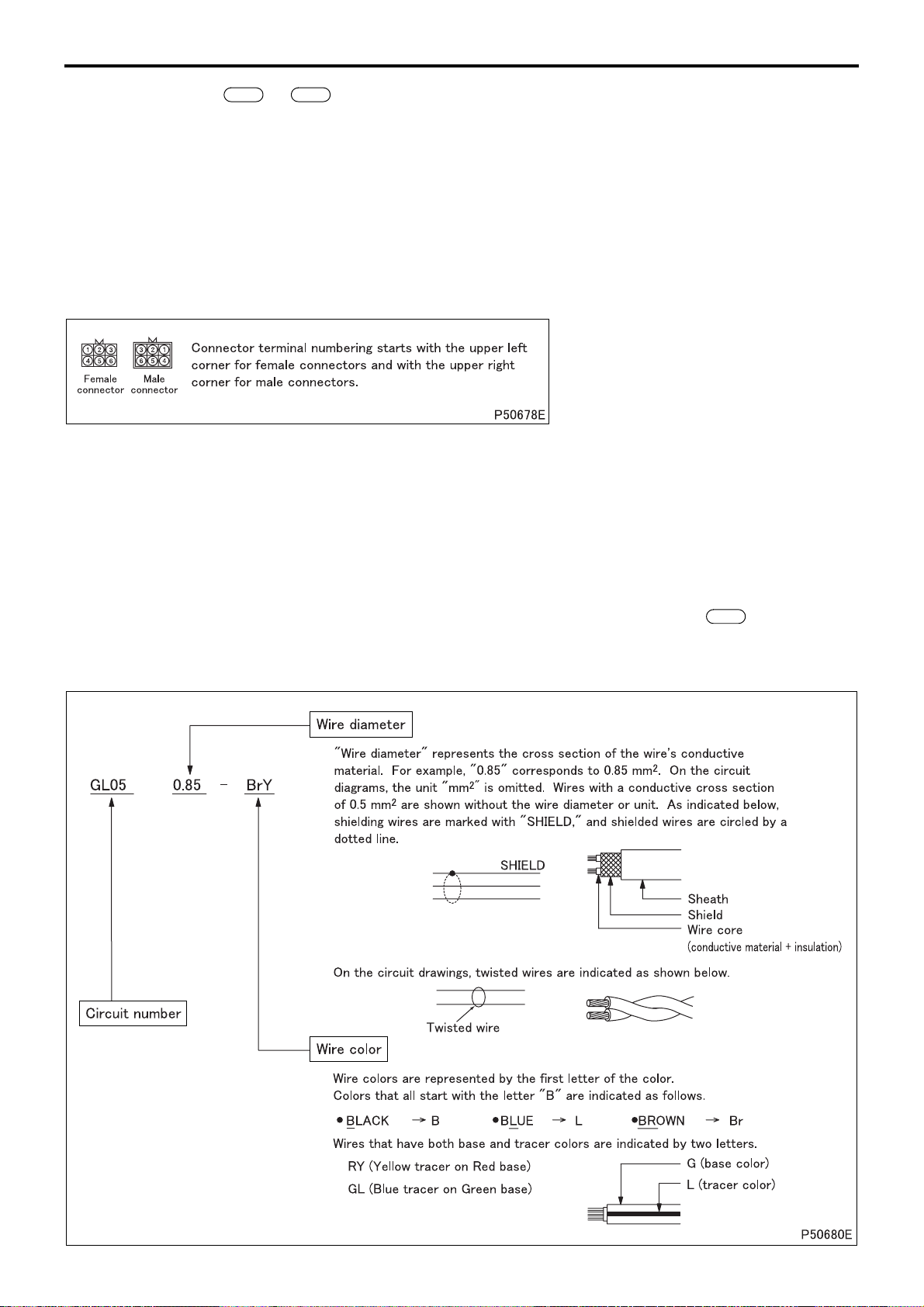
3.4 Connector type (type indication)
• A list of the connectors used is included in Gr54-14.
3.5 Connector terminal number
3.6 Major harness division
• Major harness divisions are shown.
3.7 Wiring variations between different specifications
• Variations in wiring/circuit between different vehicle specifications are clearly indicated as shown.
3.8 Code number: #001 to #999
• Code numbers are reference numbers to find individual electrical equipment inspection procedures. The inspec-
tion procedure for a electrical equipment can be found using its code number shown in a circuit diagram.
3.9 Grounding point: [1] to [99]
• Locations where wires are grounded to the vehicle. All of the grounding points are listed in .
130
3.10 Harness connection
• The arrow in the wiring diagram indicates where harnesses are connected, and NOT the flow of electricity.
3.11 Circuit number, wire diameter, wire color
00-14
Page 20

(1) Wire color
Wire color Base color + tracer
BBlackBW
Br Brown BrW
GGreenGW
Gr,
Gy
LBlueLW
Lg
O Orange OL
PPinkPB
Pu Purple
RRedRW
Sb Sky blue
VVioletVY
WWhiteWR
YYellow
green
Gray
Light
GrL,
GyL
LgR
YR
YP
Black/
white
Brown/
white
Green/
white
Gray/
blue
Blue/
white
Light
green/
Orange/
blue
Pink/
black
Red/
white
Violet/
yellow
White/
Yell ow /
Yell ow /
pink
BY
BrB
GR
GrR,
GyR
LR Blue/red LY
LgY
red
OB
PG
RB
VW
WB
red
YB
red
YV
Black/
yellow
Brown/
black
Green/
red
Gray/
red
Light
green/
yellow
Orange/
black
Pink/
green
Red/
black
Violet/
white
White/
black
Yell ow /
black
Yell ow /
violet
BR Black/red BG
BrY
GY
LgB
OG
PL
RY
VR Violet/red VG
WL
YG
Brown/
yellow
Green/
yellow
Blue/
yellow
Light
green/
black
Orange/
green
Pink/
blue
Red/
yellow
White/
blue
Yell ow /
green
BrR
GB
LB
LgW
PW
RG
WG
YL
Black/
green
Brown/
red
Green/
black
Blue/
black
Light
green/
white
Pink/
white
Red/
green
Violet/
green
White/
green
Yell ow /
blue
BL
BrG
GL
LO
RL Red/blue RO
WO
YW
Black/
blue
Brown/
green
Green/
blue
Blue/
orange
White/
orange
Yellow/
white
GO
LG
YO
00
Green/
orange
Blue/
green
Red/
orange
Yellow/
orange
00-15
Page 21
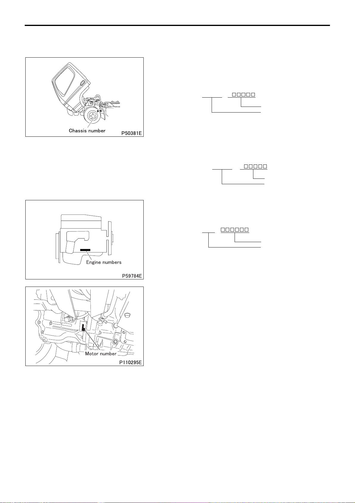
CHASSIS NUMBER, ENGINE NUMBER, MOTOR NUMBER AND NAME PLATE
• Serial chassis and engine numbers are assigned to the vehicles and engines in manufacturing sequence. Every
vehicle and engine has its own number. These numbers are required for registration and related inspection of the
vehicle.
Chassis number
<Type 1>
• The chassis number is indicated on the left frame, near the left
front wheel.
Example: FE84BE – A
Chassis number
Vehicle number
<Type 2>
• The chassis number is included in the vehicle identification number (V.I.N), which is stamped on the left-hand frame near the left
front wheel.
Example: JLF FE84BE0K J
Chassis number
Vehicle number
Engine number
• The engine number is indicated on the right side of the crank-
case.
Example: 4M42 –
Engine number
Engine model
Motor number
• The motor number is indicated on the left below part of the
clutch housing.
Example: S10B12345
00-16
Page 22

00
Name plate
<Type 1>
• Name plate contains the following information.
• MODEL
• Chassis number
• Engine number
• Wheel base
<Type 2>
• Vehicle compliance and date plate are attached to the assistant
driver’s side door opening. The compliance plate certifies that
your vehicle complied with Australian Design Rules at the time
of manufacture. In all correspondence related to your vehicle the
following information should be quoted.
• The engine number.
• The vehicle identification number (V.I.N.) – shown on compli-
ance plate.
• The S.O.A. No. (where applicable), option code, paint and
trim codes located on date plate.
00-17
Page 23
PRECAUTIONS FOR MAINTENANCE OPERATION
• Before performing service operations, inquire into the customer’s complaints and ascertain the conditions by
checking the total distance traveled, the conditions under which the vehicle is operated, and other relevant factors
about the vehicle. And note the necessary information. This information will help you to service the vehicle efficiently.
• Check the location of the fault, and identify its cause. Based on
your findings, determine whether parts must be removed or disassembled. Then, follow the service procedure given in this
manual.
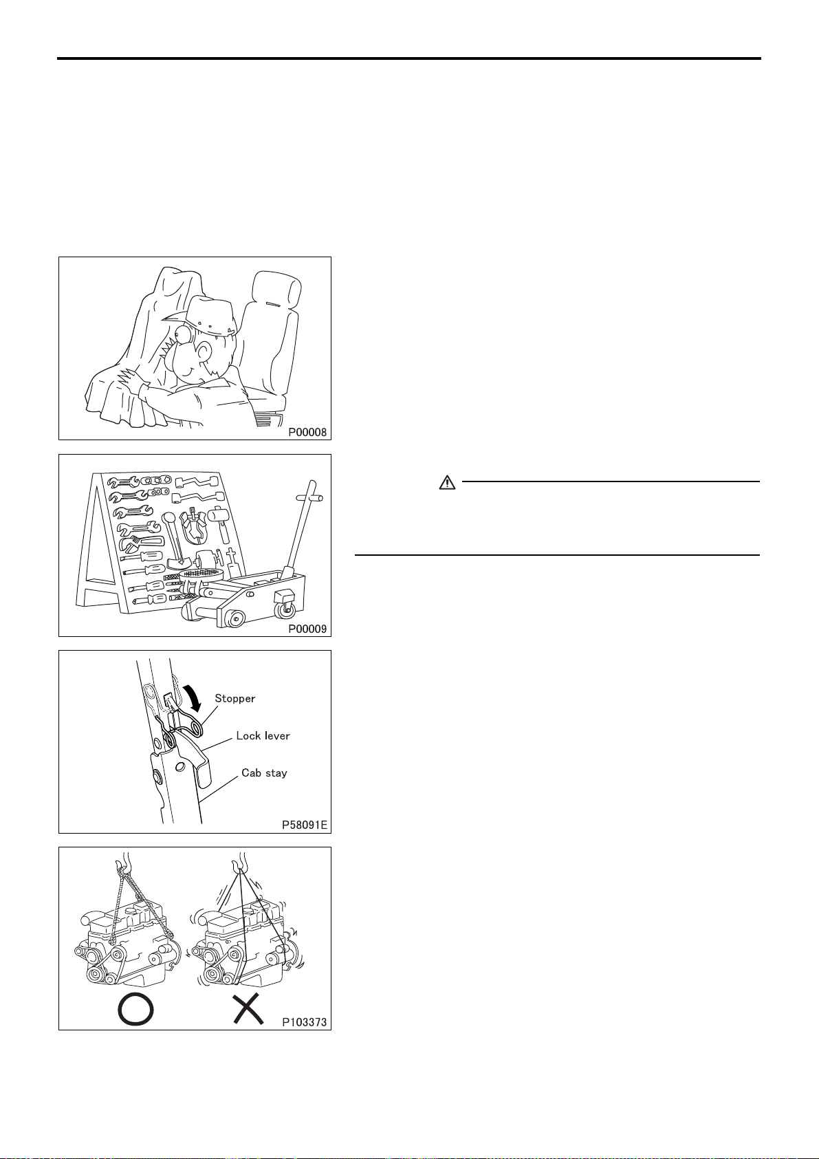
• Perform service operations on a level surface. Before starting,
take the following preparatory steps:
• To prevent soiling and damage, place covers over the seats,
trim and floor in the cab and over the paintwork of the body.
• Prepare all the general and special tools necessary for the job.
WARNING
• Special tools must be used wherever specified in this manual. Do not attempt to use other tools since they could
cause injuries and/or vehicle damage.
• After manually tilting the cab, be sure to engage the stopper with
the lock lever to secure the cab stay in a rigid state.
• Take extreme care when removing/installing heavy items such
as engine, transmission and axle. When lifting heavy items using
a cable etc., observe the following precautions.
00-18
• Identify the mass of the item being lifted. Use a cable that is
strong enough to support the mass.
• When lifting the engine, always use the engine hanger.
Page 24
00
• If lifting eyes are not provided on the item being lifted, tie a ca-
ble around the item taking into account the item’s center of
gravity.
• Do not allow anyone to pass or stay under a lifted item that
may fall.
• Never work in shoes that have oily soles.
When working with a partner or in a group, use pre-arranged signals and pay constant attention to safety. Be careful not to touch
switches and levers unintentionally.
• Inspect for oil leakage etc. before washing the vehicle. If the order is reversed, any oil leakage or fault that may exist could go
unnoticed during inspection.
• Prepare replacement parts ready for installation.
00-19
Page 25
PRECAUTIONS FOR MAINTENANCE OPERATION
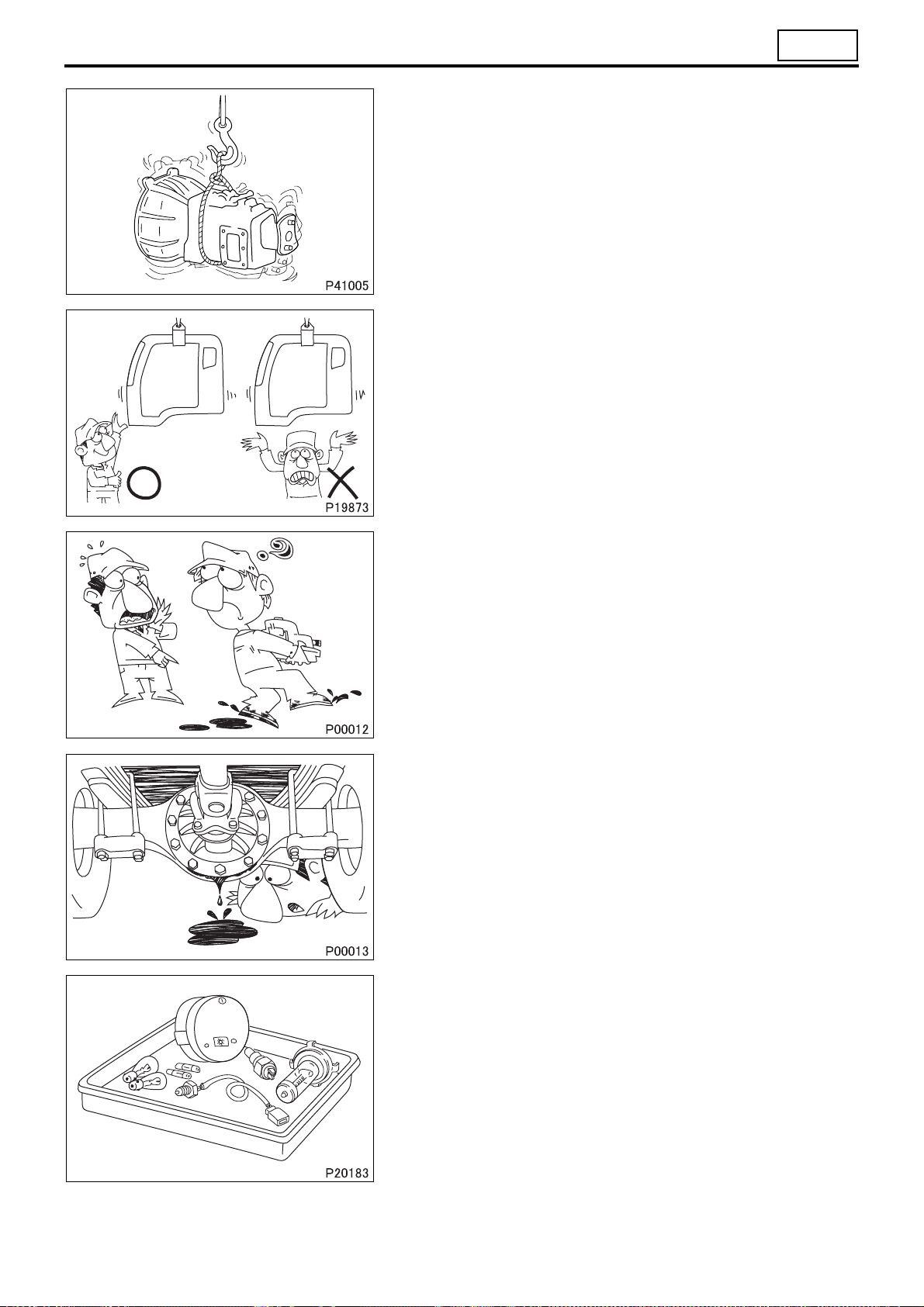
• Oil seals, packings, O-rings and other rubber parts, gaskets, and
split pins must be replaced with new ones after removal. Use
only genuine MITSUBISHI replacement parts.
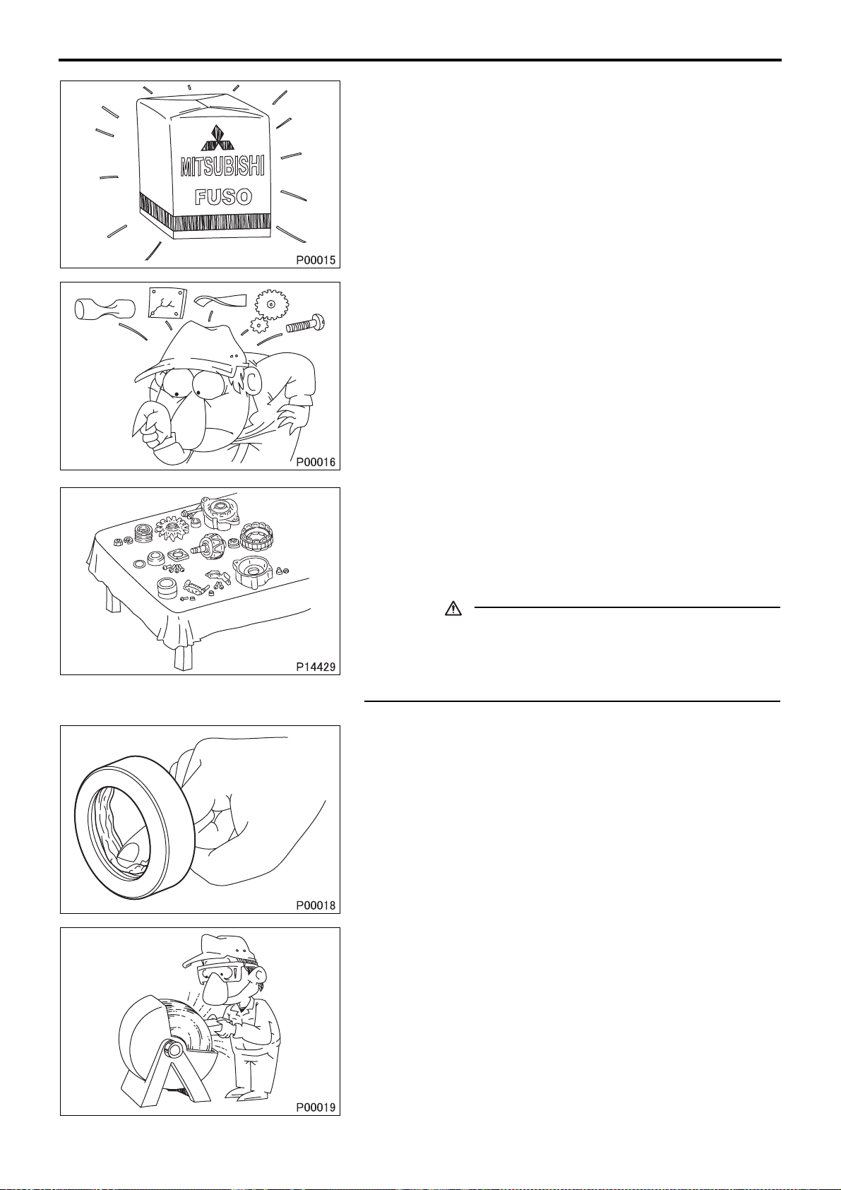
• When disassembling parts, visually check them for wear, cracks,
damage, deformation, deterioration, rust, corrosion, defective rotation, fatigue, clogging and any other possible defect.
• To facilitate correct reassembly of parts, make alignment marks
on them before disassembly and arrange disassembled parts
neatly. Make punch marks and other alignment marks where
they will not detract from parts’ functionality and appearance.
• After removing parts from the vehicle, cover the area to keep it
free of dust.
CAUTION
• Be careful not to mix up identical parts, similar parts and
parts that have left/right alignments.
• Keep new replacement parts and original (removed) parts
separately.
• Apply the specified oil or grease to U-seals, oil seals, dust seals
and bearings before reassembly.
• Always use the specified oils and greases when performing inspection or replacement. Immediately wipe away any excess oil
or grease with a rag.
00-20
• Wear safety goggles when using a grinder or welder. Wear
gloves when necessary, and watch out for sharp edges and other items that might wound your hands.
Page 26
00
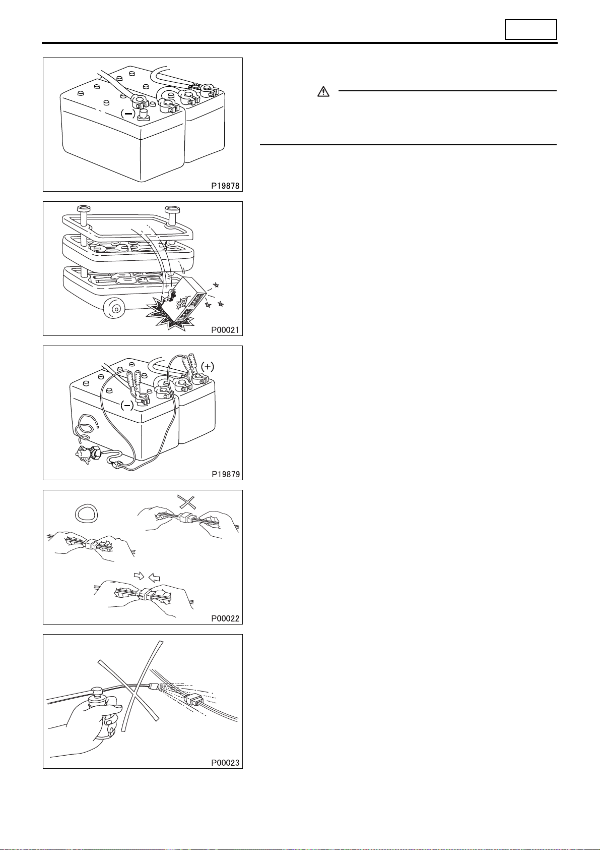
• Before working on the electrical system, disconnect the (–) bat-
tery cable to prevent short circuits.
CAUTION
• Make sure the starter switch and lighting switches are OFF
before disconnecting or connecting battery cable.
Semiconductor components may otherwise be damaged.
• Carefully handle sensors relays, and other items that are sensi-
tive to shock and heat. Do not remove or paint the cover of any
control unit.
• When applying a voltage to a part for inspection purposes,
check that the (+) and (–) cables are connected properly then
gradually increase the voltage from zero. Do not exceed the
specified voltage.
Remember that control units and sensors do not necessarily operate on the battery voltage.
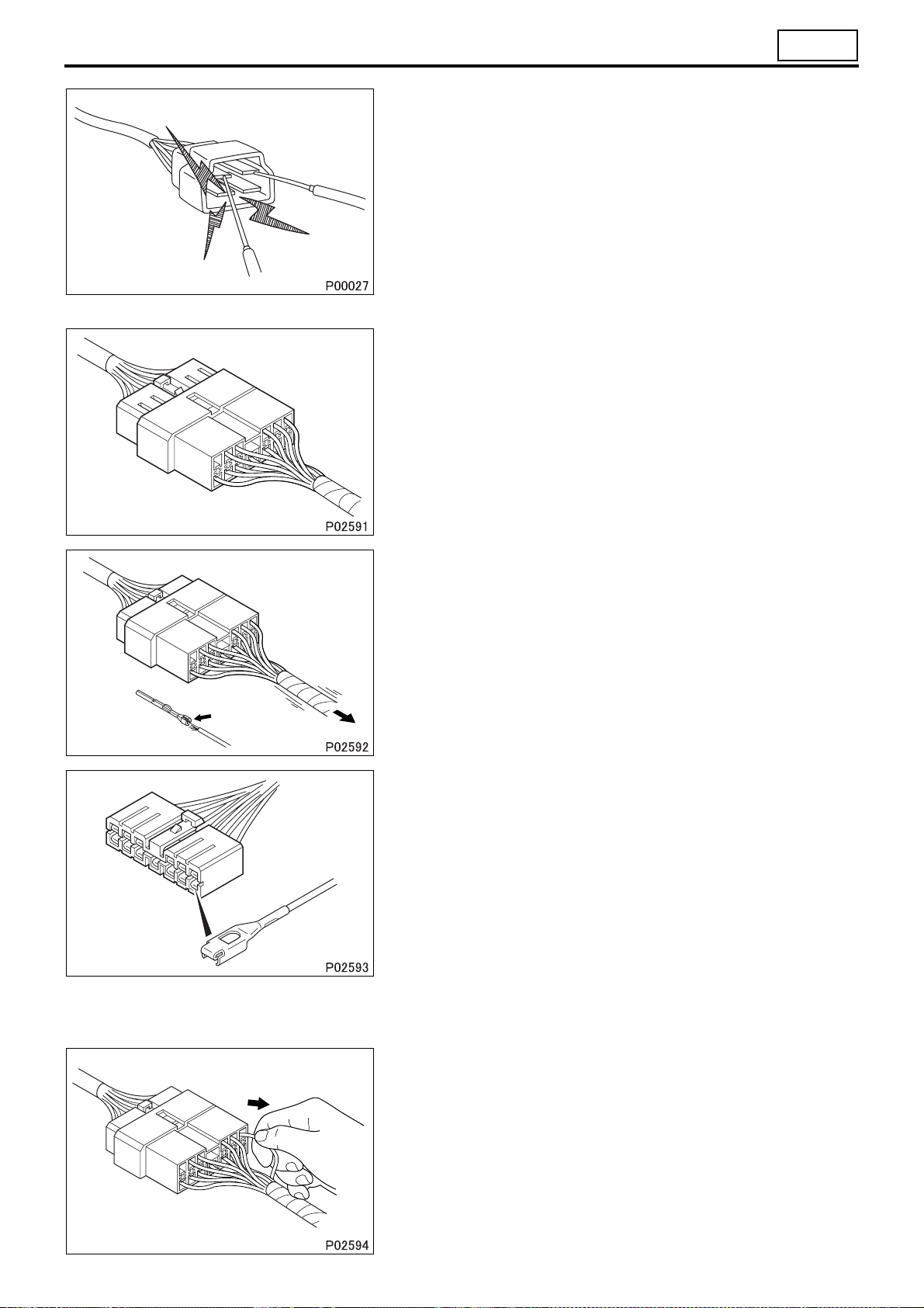
• When separating connectors, grasp the connectors themselves
rather than the harnesses.
• To separate locking connectors, first push them in the direction
of the arrows. To reconnect locking connectors, push them together until they click.
• Before washing the vehicle, cover electrical parts to keep them
dry. (Use plastic sheets or the like.) Keep water away from harness connectors and sensors and immediately wipe off any water that gets on them.
00-21
Page 27
PRECAUTIONS FOR MAINTENANCE OPERATION
1. Handling Precautions for Electric Circuits
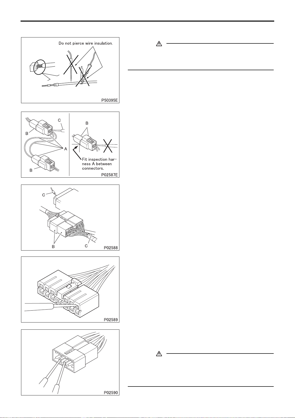
CAUTION
• Do not pierce wire insulation with test probes or alligator
clips when performing electrical inspections. Doing so can,
particularly with the chassis harness, hasten corrosion.
1.1 Inspection of harnesses
(2) Inspections with connectors fitted together
(2.1) Waterproof connectors
• Connect an inspection harness and connector A between the
connectors B of the circuit to be inspected. Perform the inspection by applying a test probe C to the connectors of the inspection harness. Do not insert the test probe C into the wire-entry
sides of the waterproof connectors since this would damage
their waterproof seals and lead to rust.
(2.2) Non-waterproof connectors
• Perform the inspection by inserting a test probe C into the wire-
entry sides of the connectors. An extra-narrow probe is required
for control unit connectors, which are smaller than other types of
connector. Do not force a regular-size probe into control unit
connectors since this would cause damage.
(3) Inspections with connectors separated
(3.1) Inspections on female terminals
• Perform the inspection by carefully inserting a test probe into the
terminals. Do not force the test probe into the terminals since
this could deform them and cause poor connections.
00-22
(3.2) Inspections on male terminals
• Perform the inspection by applying test probes directly to the
pins.
.
CAUTION
• Be careful not to short-circuit pins together with the test
probes. With control unit connectors, short-circuiting of
pins can cause damage to the control unit’s internal circuitry.
Page 28
00
• When using a multimeter to check continuity, do not allow the
test probes to touch the wrong terminals.
1.2 Inspection of connectors
(1) Visual inspection
• Check that the connectors are fitted together securely.
• Check whether wires have been separated from their terminals
due to pulling of the harness.
• Check that male and female terminals fit together tightly.
• Check for defective connections caused by loose terminals, by
rust on terminals, or by contamination of terminals by foreign
substances.
(2) Checking for loose terminals
• If connector terminal retainers become damaged, male and fe-
male terminals may not mate with each other when the connector bodies are fitted together. To check for such terminals, gently
pull each wire and see whether any terminals slip out of their
connector housings.
00-23
Page 29

PRECAUTIONS FOR MAINTENANCE OPERATION
1.3 Inspections when a fuse blows
• Remove the fuse, then measure the resistance between ground
and the fuse’s load side.
Next, close the switch of each circuit connected to the fuse. If
the resistance measurement between any switch and ground is
zero, there is a short circuit between the switch and the load. If
the resistance measurement is not zero, the circuit is not currently short-circuited; the fuse probably blew due to a momentary short circuit.
• The main causes of short circuits are as follows:
• Harnesses trapped between chassis parts
• Harness insulation damage due to friction or heat
• Moisture in connectors or circuitry
• Human error (accidental short-circuiting of components)
1.4 Inspection of chassis ground
• A special ground bolt is used to tighten a ground terminal. When
servicing the ground point, be sure to follow the procedures described below:
• When reinstalling the ground bolt
• When relocating the ground point
2. Service Precautions for Alternators
• When servicing alternators, observe the following precautions:
• Never reverse the polarity of battery connections.
Tighten the ground bolt to the specified torque.
A special ground bolt must be used. Spot-weld a nut to a
frame and tighten the ground bolt to the specified torque. Be
sure to apply touch-up paint to the welded point.
If the polarity of the battery connections were to be reversed,
a large current would flow from the battery to the alternator,
damaging the diodes and regulator.
00-24
• Never disconnect the battery cables with the engine running.
Disconnection of the battery cables during engine operation
would cause a surge voltage, leading to deterioration of the diodes and regulator.
Page 30
00
• Never perform inspections using a high-voltage multimeter.
The use of a high-voltage multimeter could damage the diodes
and regulator.
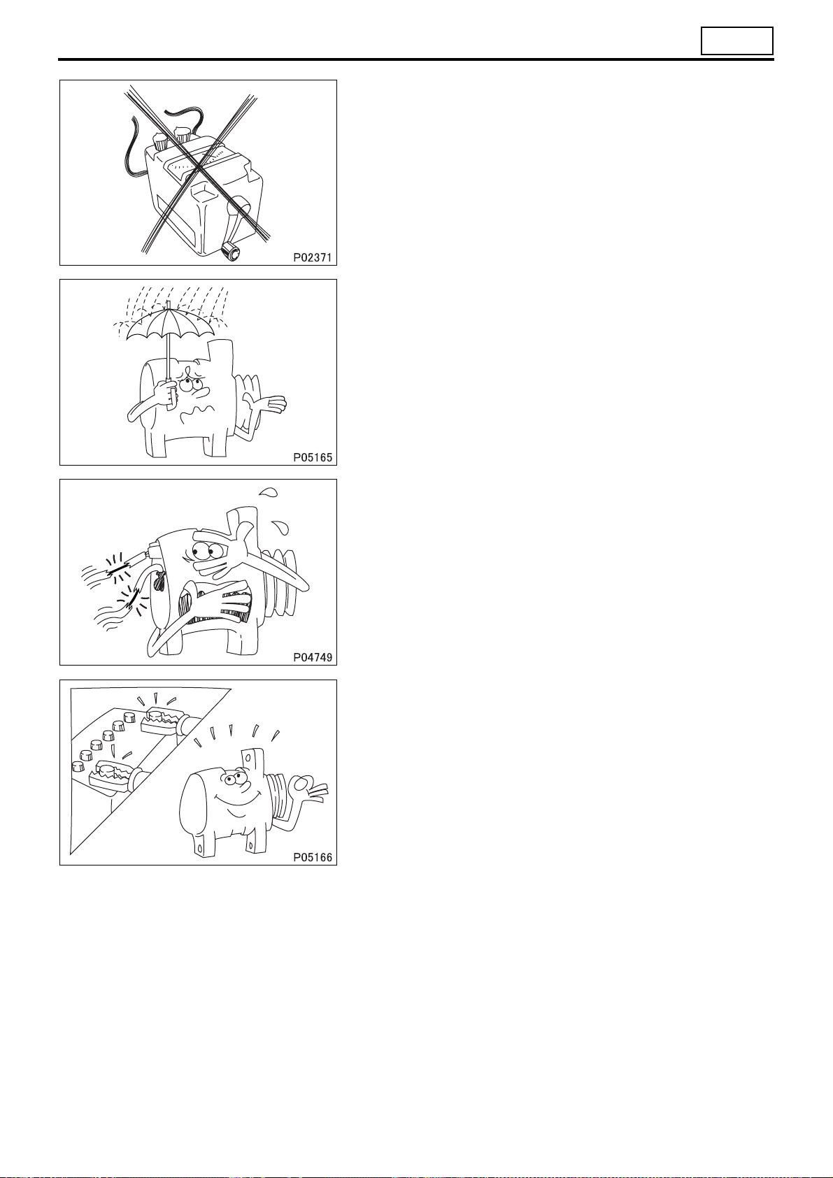
• Keep alternators dry.
Water on alternators can cause internal short circuits and damage.
• Never operate an alternator with the B and L terminals short-circuited. Operation with the B and L terminals connected together
would damage the diode trio.
• Disconnect the battery cables before quick-charging the battery
with a quick charger.
Unless the battery cables are disconnected, quick-charging can
damage the diodes and regulator.
00-25
Page 31

PRECAUTIONS FOR MAINTENANCE OPERATION
3. Intermittent Faults
• An intermittent fault typically occurs only under certain operating
conditions. Once these conditions have been identified, the
cause of the intermittent fault can be ascertained easily. First,
ask the customer about the vehicle operating conditions and
weather conditions under which the fault occurs. Also ask about
the frequency with which the fault occurs and about the fault
symptoms. Then, reproduce the fault based on this information.
In accordance with the conditions under which the fault occurs,
determine whether the fault is caused by vibration, heat or other
factors. if vibration is a possible factor, see if the fault can be reproduced by performing the following checks on individual connectors and other parts:
• Gently move connectors up and down and to left and right.
• Gently move wiring harnesses up and down and to left and
right.
• Gently wiggle sensors and other devices by hand.
• Gently wiggle wiring harnesses on suspension systems and
other moving parts.
• Connectors and other parts to be checked are those included or
given as likely fault locations in inspection procedures corresponding to diagnosis codes and/or fault symptoms.
00-26
Page 32

00
4. Precautions for Arc Welding
• When arc welding is performed, current from the welder flows to ground via the vehicle’s metal parts. Unless ap-
propriate steps are taken, this current can damage control units, other electrical devices and wiring harnesses.
And any electrical device near the point on the vehicle to which the (–) cable of the welder is connected, might be
largely damaged.
• Current flows backward as shown below.
4.1 From battery (–) cable
To prevent damage to the battery and to electrical devices that are
connected directly to the battery, it is essential to disconnect the
battery’s (–) cable.
4.2 Procedure
• Turn the starter switch to the LOCK position.
• Disconnect the battery’s (–) cable.
• Remove the safety plug of the high voltage battery box referring
to Gr18 HYBRID ELECTRIC VEHICLE SYSTEM.
• Cover all parts of the vehicle that may be damaged by welding
sparks.
• Connect the welder’s (–) cable to the vehicle as close as possible to the area being welded. Do not connect the welder’s (–) cable to the cab if the frame is being welded, and vice versa.
• Set the welding current in accordance with the part being welded.
5. Maintenance for Trucks with Airbags
• For maintenance of SRS airbags and seat belts with pretensioners, work should be conducted safely by following
the work procedure and precautions.
6. Precautions When Starting the Engine
• The engine warning lamp may illuminate if the starter switch is kept turned to the START position for a while with
the gear engaged. (Diagnosis code P0016 “No SNSR Offset/Backup Mode” of the engine electronic control unit
occurs.)
• If the engine warning lamp illuminated, place the transmission in neutral and turn the starter switch from OFF to
ON four times to turn off the warning lamp.
00-27
Page 33

JACKING UP THE VEHICLE
<Front of Vehicle>
Jacking up procedure
1 Apply chocks to the rear wheels.
2 Raise the front of the vehicle using a bottle jack or garage jack.
3 Place rigid racks to support the frame on the front side of the vehicle.
WARNING
• Apply chocks to the rear wheels to hold the vehicle in place.
• Do not remove the chocks until service operations are finished.
• It is extremely dangerous to support the vehicle with a bottle jack or garage jack alone. Use rigid racks
additionally to support the frame on the front side of the vehicle.
• Leave the bottle jack or garage jack and rigid racks in place until all service operations are completed. Be
sure not to remove them during work.
00-28
Page 34

<Rear of Vehicle>
00
Jacking up procedure
1 Apply chocks to the front wheels.
2 Raise the rear of the vehicle using a bottle jack or garage jack.
3 Place rigid racks to support the frame on both sides of the vehicle.
WARNING
• Apply chocks to the front wheels to hold the vehicle in place.
• Do not remove the chocks until service operations are finished.
• It is extremely dangerous to support the vehicle with a bottle jack or garage jack alone. Use rigid racks
additionally to support the frame on both sides of the vehicle.
• Leave the bottle jack or garage jack and rigid racks in place until all service operations are completed. Be
sure not to remove them during work.
00-29
Page 35

DIAGNOSIS CODES
1. Diagnosis Codes
• Diagnosis codes indicate the faulty sections of the vehicle.
• A fault can be repaired by reading out the diagnosis code(s) stored in the control unit and performing the remedy
for that code(s).
• Diagnosis codes can be displayed in the following two methods. Select either of them according to the system to
be diagnosed.
• Using a Multi-Use Tester
• Using flashing of a warning lamp on meter cluster
• The table below indicates the systems for which diagnosis codes can be displayed and the methods usable for in-
dividual systems.
1.1 Systems and diagnosis code displaying methods
Diagnosis codes
Warning
lamp
System
Common rail
Turbo charger
Diesel particulate filter
Exhaust gas recirculation 17
Starter continuous energizing preventing function
Pre-heat control
displaying methods
Multi-Use
Te st e r
OO
Flashing of
warning lamp
Reference
Gr
13
15
54
Hybrid electric vehicle system O O 18
O
(ORANGE)
INOMAT-II
Power anti-lock brake system O O 35EA
Hill start assist system O O 35EB
SRS airbag O – 52
(Gear shift
indicator indi-
cation)
O 22E
1.2 Types of diagnosis codes
(1) Present diagnosis code
• Fault developed in the vehicle after the starter switch is set to ON is indicated by corresponding diagnosis code.
• The fault warning lamp is lit at the same time.
(2) Past diagnosis code
• Past fault developed in the vehicle is indicated by corresponding diagnosis code stored in the memory of the elec-
tronic control unit.
• With the vehicle restored to its normal condition or the starter switch turned from OFF to ON after inspection or repair against present diagnosis codes, the present diagnosis code is stored as past diagnosis codes in the memory
of the electronic control unit.
• When reading out the past diagnosis codes, the warning lamp does not illuminate as such codes do not indicate
the current fault.
00-30
Page 36

2. Reading and Erasing the Diagnosis Code
2.1 Using a Multi-Use Tester
(1) Connecting a Multi-Use Tester
Special tools
Mark Tool name and shape Part No. Application
00
SOFTWARE DISC
Multi-Use Tester-III
SOFTWARE DISC
V.C.I. MH062927
Multi-Use Tester test
Harness E
A: Harness for inspection and drive recorder
B: Harness for drive recorder
C: Drive recorder harness
D: Cigarette lighter
plug harness
FMS-E09-2*
(Multi-Use
Tester-III version)
MH063659
A: MH063661
B: MH063663
C: MH063665
D: MH063666
*Installation of the Multi-Use Tester-III
or version-up of the current version
into Multi-Use Tester-III SOFTWARE
DISC (Pub. No. SG0901A)
Data transmission between electronic
control unit and PC
Power supply to V.C.I. and communication with electronic control unit
Multi-Use Tester test
harness D
(used for extension)
USB cable MH063668
MH062951
Multi-Use Tester test harness B extension
Communication between V.C.I. and
PC
00-31
Page 37

DIAGNOSIS CODES
(1.1) To perform system inspection
• Move the starter switch to the LOCK position.
• Connect PC installed , , -A and as shown.
• Connect -A connector to the Multi-Use Tester connector on
the vehicle.
(1.2) To use drive recorder function
• Move the starter switch to the LOCK position.
• Connect PC installed , , -A, -C, -D and
as shown.
• Connect -C connector to the Multi-Use Tester connector on
the vehicle.
• Connect the cigarette lighter plug of -D to the cigarette light-
er socket on the vehicle.
(1.3) To extend the Multi-Use Tester test harness
• Connect to -A to extend the test harness to use the
Multi-Use Tester outside the vehicle.
00-32
Page 38

00
(2) Access of diagnosis code
• Set the starter switch to ON.
• Operate the Multi-Use Tester for a display of necessary diagnosis code stored in the memory of the electronic
control unit and identify the location of the fault.
(3) Clearing of diagnosis code
• Set the starter switch to ON (the engine not to be started).
• Operate the Multi-Use Tester to delete all the diagnosis codes stored in the memory of the electronic control unit.
2.2 Using flashing of a warning lamp on meter cluster
(1) Engine control, Power anti-lock brake system, Hill start assist system, Hybrid electric vehicle system
• Using the diagnosis and memory clear
switches, display diagnosis codes.
• Diagnosis codes of the battery electronic control unit are sent to the motor
electronic control unit and are displayed along with those of the motor
electronic control unit by the diagnosis
switch operation.
However, some diagnosis codes (minor faults) can be checked only with
the Multi-Use Tester.
CAUTION
• Opening the memory clear switch
followed by its reconnection will
erase the stored diagnosis codes
from the memory. To avoid inadvertently erasing necessary codes,
be sure to read well the procedure
described below before handling diagnosis codes.
00-33
Page 39

DIAGNOSIS CODES
(1.1) Reading diagnosis codes
• To read a diagnosis code, observe how may times the warning
lamp flashes and how long each illumination lasts.
• The duration of illumination differs between the first and second
digits.
• Second digit: 1.2 sec.
• First digit: 0.4 sec.
• A diagnosis code consists of the flashing of second digit and the
flashing of first digit in that order. If a diagnosis code has “0” in
the second digit, only the first digit will be displayed.
• The diagnosis code 01 will be displayed if the system is normal.
• The same diagnosis code will be displayed 3 times in a row be-
fore moving to the display of the next code.
• After the last diagnosis code is displayed, the first code will be
displayed again 3 times in a row and then the subsequent
codes. This will be repeated.
(1.2) Present diagnosis codes
• Turn the starter switch ON.
• Remove the diagnosis switch.
• Present diagnosis codes will be displayed by flashing of the
warning lamp.
• When the diagnosis switch is connected, electronic control unit
will stop (terminate) displaying diagnosis codes.
(1.3) Present and past diagnosis codes
• Turn the starter switch to the ON position.
• Open the diagnosis switch.
• Present diagnosis codes will be displayed by flashing of the
warning lamp.
• Open the memory clear switch.
• Present and past diagnosis codes will be displayed by flashing
of the warning lamp.
• Turn the starter switch to the OFF position and connect the
memory clear switch and diagnosis switch to terminate the diagnosis code displaying mode.
00-34
(1.4) Erasing diagnosis codes
• Turn the starter switch to the ON position (do not start the en-
gine).
• Open the memory clear switch and reconnect it; all diagnosis
codes stored in electronic control unit memory will be erased.
To cancel diagnosis code erasure after opening the memory
clear switch, turn the starter switch to the OFF position and then
reconnect the memory clear switch.
• Erase the diagnosis codes stored in the battery electronic control unit using the Multi-Use Tester.
Page 40

(2) INOMAT-II
00
• Display diagnosis codes using the di-
agnosis switch and memory clear
switch.
NOTE
• Diagnosis codes are erased by disconnecting and connecting operation of the memory clear switch.
Fully understand the procedures
before working.
(2.1) Reading diagnosis codes
• To read a diagnosis code, check the indication of the gear shift
indicator.
Example:If the codes are 12 and 34, they will be displayed as
shown in the drawing.
• If the system is normal, the diagnosis code 01 will be displayed.
• Diagnosis codes will be displayed each code once in the reverse
chronological order.
• After the last diagnosis code is displayed, the first code will be
displayed again and then the subsequent codes. This will be repeated.
(2.2) Present diagnosis codes
• Turn the starter switch to ON.
• Disconnect the diagnosis switch.
• The present diagnosis codes will be displayed on the gear shift
indicator.
• When the diagnosis switch is connected, ECU will stop (terminate) displaying diagnosis codes.
(2.3) Present and past diagnosis codes
• Turn the starter switch to ON.
• Disconnect the diagnosis switch.
• The present diagnosis codes will be displayed on the gear shift
indicator.
• Disconnect the memory clear switch.
• The present and past diagnosis codes will be displayed on the
gear shift indicator.
• After the starter switch is turned to OFF, connect the memory
clear switch and diagnosis switch to terminate the operation.
(2.4) Erasing diagnosis codes
• Turn the starter switch to ON. (Do not start the engine.)
• All diagnosis codes stored in the electronic control unit can be
erased by disconnecting the memory clear switch and then connecting it again. If you discontinue the operation after the memory clear switch is disconnected, turn the starter switch to OFF
and then connect the memory clear switch.
00-35
Page 41

TABLE OF STANDARD TIGHTENING TORQUES
• Use specified bolts and nuts. Tighten them to the torques shown below as appropriate, unless otherwise speci-
fied.
• Threads and bearing surfaces shall be dry.
• If the mating nut and bolt (or stud bolt) are different in level of strength, tighten them to the torque specified for the
bolt.
Hexagon Head Bolts and Stud Bolts (Unit: N·m {kgf·m})
Strength
Identification
symbol
Nominal
diameter (stud) (stud) (stud)
M5
M6
M8
M10
M12
M14
M16
M18
M20
M22
M24
2 to 3
{0.2 to 0.3}
4 to 6
{0.4 to 0.6}
9 to 13
{0.9 to 1.3}
18 to 27
{1.8 to 2.7}
34 to 50
{3.4 to 5.1}
60 to 80
{6.0 to 8.0}
90 to 120
{9 to 12}
130 to 170
{14 to 18}
180 to 240
{19 to 25}
250 to 330
{25 to 33}
320 to 430
{33 to 44}
4T 7T 8T
–
–
–
17 to 25
{1.8 to 2.6}
31 to 45
{3.1 to 4.6}
55 to 75
{5.5 to 7.5}
90 to 110
{9 to 11}
120 to 150
{12 to 16}
170 to 220
{17 to 22}
230 to 300
{23 to 30}
290 to 380
{29 to 39}
4 to 6
{0.4 to 0.6}
7 to 10
{0.7 to 1.0}
16 to 24
{1.7 to 2.5}
34 to 50
{3.5 to 5.1}
70 to 90
{7.0 to 9.5}
110 to 150
{11 to 15}
170 to 220
{17 to 23}
250 to 330
{25 to 33}
340 to 460
{35 to 47}
460 to 620
{47 to 63}
600 to 810
{62 to 83}
–
–
–
32 to 48
{3.3 to 4.9}
65 to 85
{6.5 to 8.5}
100 to 140
{11 to 14}
160 to 210
{16 to 21}
220 to 290
{23 to 30}
310 to 410
{32 to 42}
420 to 560
{43 to 57}
540 to 720
{55 to 73}
5 to 7
{0.5 to 0.7}
8 to 12
{0.8 to 1.2}
19 to 28
{2.0 to 2.9}
45 to 60
{4.5 to 6.0}
80 to 105
{8.5 to 11}
130 to 170
{13 to 17}
200 to 260
{20 to 27}
290 to 380
{30 to 39}
400 to 530
{41 to 55}
540 to 720
{55 to 73}
700 to 940
{72 to 96}
–
–
–
37 to 55
{3.8 to 5.7}
75 to 95
{7.5 to 10}
120 to 160
{12 to 16}
190 to 240
{19 to 25}
250 to 340
{26 to 35}
360 to 480
{37 to 49}
490 to 650
{50 to 67}
620 to 830
{63 to 85}
Hexagon Head Flange Bolts (Unit: N·m {kgf·m})
Strength
Identification
Nominal
diameter
M6
M8
M10
M12
symbol
4 to 6
{0.4 to 0.6}
10 to 15
{1.0 to 1.5}
21 to 31
{2.1 to 3.1}
38 to 56
{3.8 to 5.5}
4T 7T 8T
–
–
20 to 29
{2.0 to 3.0}
35 to 51
{3.5 to 5.2}
8 to 12
{0.8 to 1.2}
19 to 28
{2.0 to 2.9}
45 to 55
{4.5 to 5.5}
80 to 105
{8.0 to 10.5}
–
–
37 to 54
{3.8 to 5.6}
70 to 95
{7.5 to 9.5}
10 to 14
{1.0 to 1.4}
22 to 33
{2.3 to 3.3}
50 to 65
{5.0 to 6.5}
90 to 120
{9 to 12}
–
–
50 to 60
{5.0 to 6.0}
85 to 110
{8.5 to 11}
00-36
Page 42

Hexagon Nuts (Unit: N·m {kgf·m})
00
Strength
Identification
Nominal
diameter
M5
M6
M8
M10
M12
M14
M16
M18
M20
M22
M24
symbol
Standard screw
thread
2 to 3
{0.2 to 0.3}
4 to 6
{0.4 to 0.6}
9 to 13
{0.9 to 1.3}
18 to 27
{1.8 to 2.7}
34 to 50
{3.4 to 5.1}
60 to 80
{6.0 to 8.0}
90 to 120
{9 to 12}
130 to 170
{14 to 18}
180 to 240
{19 to 25}
250 to 330
{25 to 33}
320 to 430
{33 to 44}
4T 6T
Coarse screw
thread
–
–
–
17 to 25
{1.8 to 2.6}
31 to 45
{3.1 to 4.6}
55 to 75
{5.5 to 7.5}
90 to 110
{9 to 11}
120 to 150
{12 to 16}
170 to 220
{17 to 22}
230 to 300
{23 to 30}
290 to 380
{29 to 39}
Standard screw thread Coarse screw thread
4 to 6
{0.4 to 0.6}
7 to 10
{0.7 to 1.0}
16 to 24
{1.7 to 2.5}
34 to 50
{3.5 to 5.1}
70 to 90
{7.0 to 9.5}
110 to 150
{11 to 15}
170 to 220
{17 to 23}
250 to 330
{25 to 33}
340 to 460
{35 to 47}
460 to 620
{47 to 63}
600 to 810
{62 to 83}
–
–
–
32 to 48
{3.3 to 4.9}
65 to 85
{6.5 to 8.5}
100 to 140
{11 to 14}
160 to 210
{16 to 21}
220 to 290
{23 to 30}
310 to 410
{32 to 42}
420 to 560
{43 to 57}
540 to 720
{55 to 73}
Hexagon Flange Nuts (Unit: N·m {kgf·m})
Strength
Identification
Nominal
diameter
M6
M8
M10
M12
symbol
Standard screw
thread
4 to 6
{0.4 to 0.6}
10 to 15
{1.0 to 1.5}
21 to 31
{2.1 to 3.1}
38 to 56
{3.8 to 5.6}
4T
Coarse screw
thread
–
–
20 to 29
{2.0 to 3.0}
35 to 51
{3.5 to 5.2}
00-37
Page 43

TABLE OF STANDARD TIGHTENING TORQUES
Tightening Torque for General-Purpose Flare Nut (Unit: N·m {kgf·m})
Pipe diameter φ4.76 mm φ6.35 mm φ8 mm φ10 mm φ12 mm φ15 mm
Tightening torque 17 {1.7} 25 {2.6} 39 {4.0} 59 {6.0} 88 {9.0} 98 {10}
Tightening Torque for General-Purpose Air Piping Nylon Tube (DIN Type) (Unit: N·m
{kgf·m})
Nominal diameter
× wall thickness
Tightening torque 20 {2.0 } 34 {3.5 } 49 {5.0 } 54 {5.5 }
Tightening Torque for General-Purpose Air Piping Nylon Tube (SAE Type) (Unit: N·m
{kgf·m})
Nominal diameter 1/4 in. 3/8 in. 1/2 in. 5/8 in.
Tightening torque 13 {1.3 } 29 {3.0 } 49 {5.0 } 64 {6.5 }
6 × 1 mm 10 × 1.25 mm 12 × 1.5 mm 15 × 1.5 mm
+60+0.6
+40+0.4
0
0
+10
+5
+1.0
0
0
+0.5
0
0
+100+1.0
+50+0.5
0
0
+50+0.5
+50+0.5
0
0
00-38
Page 44

GROUP 11 ENGINE
SPECIFICATIONS .............................................................................. 11-2
STRUCTURE AND OPERATION
1. Exploded View ............................................................................. 11-3
2. Cylinder Head and Cylinder Head Gasket .................................... 11-4
3. Valve Mechanism ......................................................................... 11-5
4. Timing Chain ............................................................................... 11-6
5. Timing Gears ............................................................................... 11-7
6. Connecting Rod ........................................................................... 11-8
7. Piston .......................................................................................... 11-8
8. Flywheel .............................................................................................. 11-9
9. Crankcase, Crankshaft and Main Bearing ..................................... 11-10
10.Oil Seal ............................................................................................. 11-13
TROUBLESHOOTING ..................................................................... 11-14
ON-VEHICLE INSPECTION AND ADJUSTMENT
1. Measuring Compression Pressure ............................................. 11-16
2. Inspection and Adjustment of Valve Clearance .......................... 11-18
3. Inspection and Replacement of Timing Chain ............................ 11-19
4. Protrusion of Timing Chain Tensioner’s Plunger ........................ 11-25
5. Damage to the Starter Pinion Contact Surface of Ring Gear ....... 11-26
ENGINE REMOVAL AND INSTALLATION........................................11-28
ROCKER COVER ............................................................................ 11-30
CAMSHAFT HOLDER AND CAMSHAFT
....................................... 11-32
CYLINDER HEAD AND VALVE MECHANISM..................................11-38
PISTON AND CONNECTING ROD ...................................................11-54
FLYWHEEL ........................................................................................11-66
TIMING GEAR CASE.........................................................................11-70
TIMING GEAR....................................................................................11-74
CRANKSHAFT AND CRANKCASE ..................................................11-80
11-1
Page 45

SPECIFICATIONS
Item Specifications
Engine model 4M42T3
Type 4-cylinder, in-line, water-cooled, 4-cycle diesel engine
Combustion chamber Direction injection type
Valve mechanism Double overhead camshaft (DOHC)
Maximum output kW {PS} /rpm 96 {130} /3200
Maximum torque N·m {kgf·m} /rpm 294 {30} /1700
Bore × stroke mm φ95 × 105
3
Total displacement cm
Compression ratio 17.0
{L} 2977 {2.977}
11-2
Page 46

STRUCTURE AND OPERATION
1. Exploded View
11
11-3
Page 47

STRUCTURE AND OPERATION
2. Cylinder Head and Cylinder Head Gasket
2.1 Cylinder head
• The arrangement of the intake ports
and exhaust ports is of a cross-flow
type. The exhaust ports are provided
on the right side and the intake ports
are provided on the left side of the cylinder head.
• Cylinder head bolt (M12) is fastened to
the upper crankcase and cylinder
head bolt (M10) is fastened to the timing gear case.
• The cylinder head bolts must be tightened according to the specified procedure.
11-4
2.2 Cylinder head gasket
• Select and use a cylinder head gasket
of a thickness that can accommodate
the piston projection.
• The size (thickness) class of the gasket can be identified by the shape of
the notches cut on the edge of each
gasket.
Page 48

3. Valve Mechanism
11
• The camshaft is driven by the timing chain. The exhaust camshaft and the intake camshaft are supported by cam-
shaft holders at the journals and are retained by camshaft caps from above.
• There are two types of rocker arms: long rocker arm and short rocker arm. They are alternately provided by the
valve position.
11-5
Page 49

STRUCTURE AND OPERATION
4. Timing Chain
• The timing chain is an endless chain with 110 links that connects the exhaust cam sprocket, intake cam sprocket
and the idler sprocket.
• The timing chain has mark link plates at three locations that indicate the position at which the crankshaft and the
camshaft should take when the chain is installed. There are two plates at the first location and one plate at the
second location. The first location (two-mark-link location) must be aligned with the mating mark “ ” on the exhaust cam sprocket and the intake cam sprocket, and the second location (one-mark-link location) must be
aligned with the mating mark “ ” on the idler sprocket.
• The chain tensioner gives tension to the timing chain. The chain tensioner has a plunger with a built-in spring.
• When the chain tensioner is installed in position, the plunger directly pushes the tension lever, and the timing
chain is tensioned automatically by a force determined by the tension of the plunger spring.
• After the plunger is installed, it is locked in place by a cam provided in the chain tensioner, which prevents accidental deflection of the timing chain while it is driven. Do not crank the engine in the reverse direction after installing the chain tensioner, as this will apply undue forces to the plunger and may cause such undesirable
consequences as cam being over ridden by the plunger.
11-6
Page 50

5. Timing Gears
11
• Each timing gear has mating mark(s) “1” or “5” to ensure that it is engaged correctly with another gear during in-
stallation.
5.1 Idler gear
• The idler gear is press fitted into the
idler sprocket, which drives the timing
chain, and rotates on the idler shaft.
• The idler shaft is anchored to the
crankcase using the idler washer and
bolt.
The idler sprocket is fitted with the
idler bushing, which is lubricated by
engine oil supplied through the oil
holes drilled in the idler shaft.
11-7
Page 51

STRUCTURE AND OPERATION
6. Connecting Rod
• The “F” mark indicates the assembly direction onto the piston and engine front side.
• The color mark indicates the diameter class of the large end.
7. Piston
• For selective fit of the pistons with the
upper crankcase, match corresponding size marks on the pistons and upper crankcase. The size marks of the
pistons are “A” through “C” and the “C”
marked piston has the largest outside
diameter.
• Install the pistons with the front marks
facing forward of the engine.
11-8
Page 52

8. Flywheel
11
• The bearing is fitted into the flywheel and held in place by the washers.
• The peripheral edge on one side of the ring gear is chamfered for easy engagement of the gear with the starter
pinion.
11-9
Page 53

STRUCTURE AND OPERATION
9. Crankcase, Crankshaft and Main Bearing
9.1 Crankcase
• The crankcase is a bi-block type con-
sisting of an upper crankcase and a
lower crankcase that are assembled to
grip the crankshaft in between.
• The upper crankcase has cylinders
whose surfaces are machined for direct contact with sliding pistons.
The walls of the cylinders have water
jackets for cooling the cylinders.
• The main cap bolts that hold the upper
crankcase and the lower crankcase together must be tightened according to
the specified procedure.
11-10
Page 54

11
• The upper crankcase is provided with
piston size marks “A”, “B” and “C”
stamped to help to select appropriate
pistons.
9.2 Crankshaft
• The crankshaft has two sets of color
marks. Color mark A indicates the outside diameter of the journals (at five
locations), and color mark B indicates
the outside diameter of the pins (at
four locations).
9.3 Main bearing
• Each upper main bearing has an oil
hole, which provides a passage for engine oil to the corresponding crankshaft journal.
• Main bearings of different thickness
are available so that the most appropriate ones can be selected to ensure
proper clearance between them and
journals.
Bearing thickness classes are identified by color marks (red, blue and yellow) painted on the sides of the
bearings.
• All the upper and lower main bearings
are identical except for the No. 3 upper bearing and the No. 3 lower bearing.
11-11
Page 55

STRUCTURE AND OPERATION
9.4 Thrust plates
• Two upper and lower thrust plate pairs
are installed on both sides of the upper and lower main bearings at the
rear most journal of the crankshaft.
• The thrust plates must be of a thickness that corresponds to the end play
of the crankshaft.
Each thrust plate has two oil grooves
to ensure its minimum friction against
the crankshaft journal.
11-12
Page 56

10.Oil Seal
11
10.1 Front oil seal
• The front oil seal is fitted in the timing
gear case, and prevents oil from leaking by contact of its lip with the crankshaft pulley.
10.2 Rear oil seal
• The rear oil seal is fitted in the rear oil
seal case, and prevents oil from leaking by contact of its lip with the crankshaft.
11-1 3
Page 57

TROUBLESHOOTING
Symptoms
Reference Gr
Possible causes
Incorrect valve clearance O O
Cylinder head and valve
mechanism
Defective timing chain-related parts O
Timing gears
Camshaft
Pistons and connecting
rods
Crankshaft
Fuel system
Cooling system
Intake and exhaust system
Incorrect oil viscosity O
Incorrectly fitted piping and hoses O
Defective/incorrectly fitted alternator and other auxiliaries O
Defective cylinder head gasket O O
Worn valve and valve seat; carbon deposits O O
Weakened valve spring O O
Worn lifter shim O
Incorrect backlash in timing gears O
Poor lubrication of timing gears and idler shaft O
Excessive end play in camshaft O
Worn camshaft O
Worn/damaged piston ring groove(s) O O
Worn/damaged piston ring(s) O O
Worn piston pin and connecting rod small end O
Excessive end play in crankshaft O
Incorrectly fitted crankshaft O
Worn/damaged crankshaft pins and connecting rod bearings
Worn/damaged crankshaft journals and main bearings O
Defective supply pump O O
Faulty fuel spray from injector O O
Air or water trapped in fuel system components O
Irregular fuel (kerosene, heavy oil, bio-fuel, etc.) is used O
Malfunctioning cooling system O
Loose/damaged belts O
Clogged air cleaner O
Clogged muffler O
Low power output
Abnormal engine noise
O
Gr13
Gr14
Gr15Malfunctioning turbocharger O O
11-14
Page 58

M E M O
11
11-1 5
Page 59

ON-VEHICLE INSPECTION AND ADJUSTMENT
1. Measuring Compression Pressure
Service standards
Location Maintenance item Standard value Limit Remedy
Each cylinder
(at 220 rpm)
– Compression pressure
Cylinder-to-cylinder pressure difference
Special tools (Unit: mm)
Mark Tool name and shape Part No. Application
Compression gauge
adaptor
2840 kPa
{29 kgf/cm2}
–
2260 kPa
{23 kgf/cm2}
295 kPa
{3 kgf/cm
2
or less
Inspect
}
Inspect
AB
M16 × 1.5 M10 × 1.25
MH063494 Measuring compression pressure
• For the hybrid electric vehicle system, there are two methods of cranking the engine, a conventional method using
the starter and a method using the motor of the hybrid electric vehicle system.
• If the engine is cranked with the motor of the hybrid electric vehicle system, measurement of compression pressure may become inaccurate since the engine speed is slightly higher than when the starter is used for cranking.
For this reason, engine cranking should be performed using the starter following the procedure below.
• Turn the starter switch quickly up to the START position before the READY indicator lamp in the meter cluster
illuminates. Though the indicator lamp illuminates in several seconds, the starter will keep running.
• If the starter switch is turned to the START position after the READY indicator lamp in the meter cluster illumi-
nates, the starter will not run and the engine is cranked with the motor of the hybrid electric vehicle system. In
this case, turn the starter switch to OFF and try again.
• A drop in compression pressure can be used as a guide to determine when the engine should be overhauled.
• Measure the compression pressure at regular intervals. Keeping track of its transmission can provide a useful tool
for troubleshooting. On new vehicles and vehicles with newly replaced parts, the compression pressure will be
somewhat higher depending on the break-in condition of piston rings, valve seats, etc., but this will return to normal as the parts wear down.
• Before the compression measurement, check that the engine oil, starter, and battery are in normal condition.
• Place the vehicle in the following conditions.
• Warm up the engine until the coolant temperature reaches approximately 80 to 90°C.
• Turn off the lights and auxiliaries.
• Place the transmission shift lever into the N position.
• Place the steering wheel in the straight-ahead position.
11-16
• Remove the fuse (M9) to prevent fuel from being injected when
the engine is cranked by the starter.
CAUTION
• When cranking the engine, never shut off the power to the
engine electronic control unit by disconnecting the engine
electronic control unit connector or the like.
If the engine is cranked while shutting off the power to the
engine electronic control unit, the electronic control unit
cannot control the supply pump and this may cause failure
to the pump.
Page 60

11
• Remove all glow plugs.
• Cover the glow plug mounting holes with shop towels. After
cranking the engine with the starter, check that no foreign substances are deposited on the shop towels.
• If there are deposits (such as engine oil or coolant) on the shop
towels, the following may be the cause:
• Deposits of engine oil alone can mean a defective piston ring
seal; the piston rings must be inspected.
• Deposits of both engine oil and coolant can mean cracks in
the cylinders or cylinder head; the crankcase or cylinder head
must be replaced.
WARNING
• When coolant and engine oil deposits are evident, crank-
ing the engine could be dangerous as these substances,
heated to high temperatures, will blow out from the glow
plug mounting holes. Make sure to stay away from the
glow plug mounting holes when the engine is being
cranked.
• Attach to one of the glow plug mounting holes and then at-
tach a compression gauge.
• Crank the engine and measure the compression pressure for all
the cylinders one after another. Determine the compression
pressure difference between the cylinders.
• If the compression pressure and the cylinder-to-cylinder pressure difference are not within the limit, pour a small amount of
engine oil into the corresponding glow plug mounting hole and
remeasure the compression pressure.
• If the compression pressure increases, the piston rings and
cylinder surfaces may be badly worn or otherwise damaged.
• If the compression pressure remains unchanged, there may
be seizure in the valves, the valves may be incorrectly seated
or the cylinder head gasket may be defective.
• Install the glow plugs. (See later sections.)
11-1 7
Page 61

ON-VEHICLE INSPECTION AND ADJUSTMENT
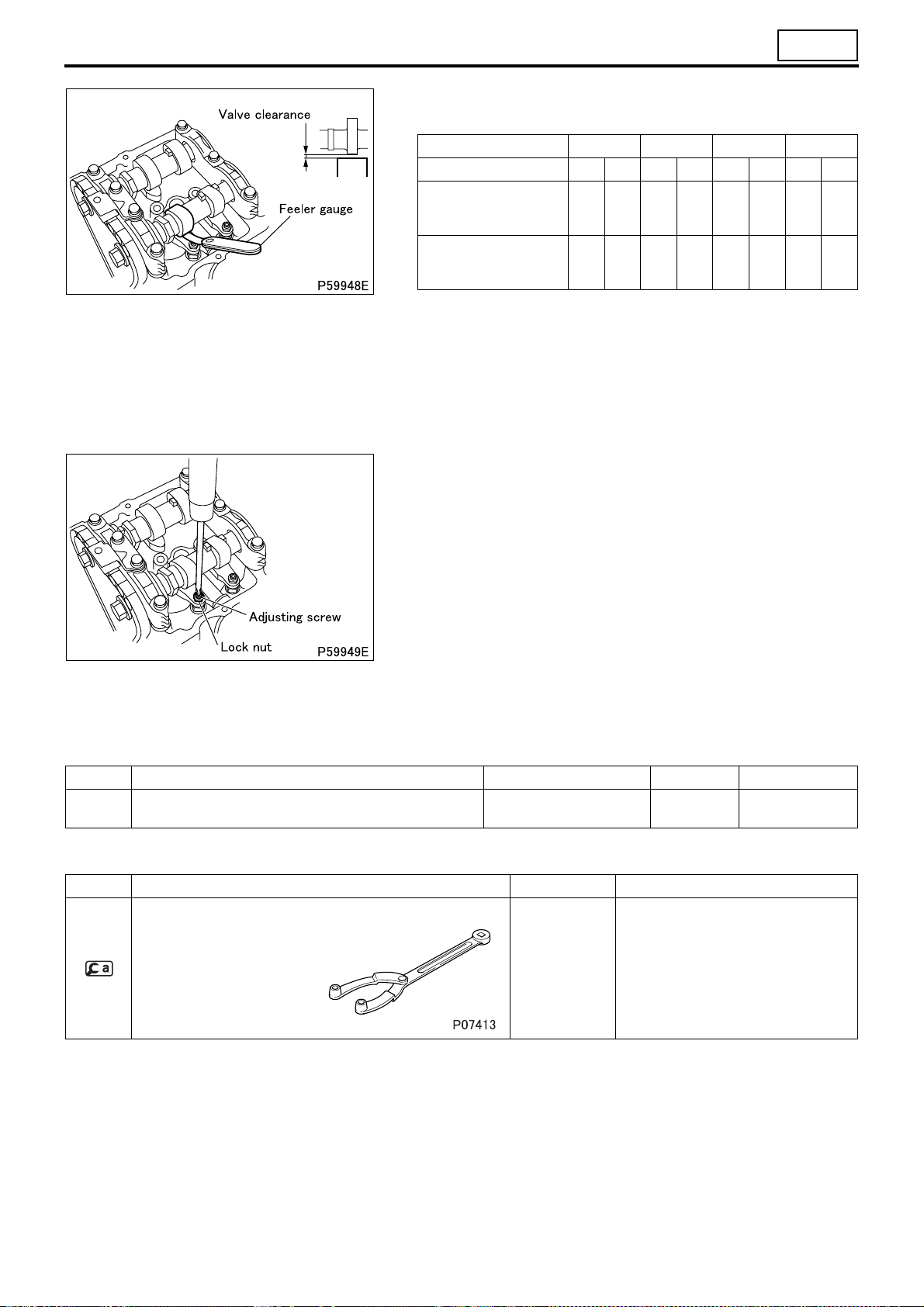
2. Inspection and Adjustment of Valve Clearance
Service standards (Unit: mm)
Location Maintenance item Standard value Limit Remedy
Valve clearance (when en-
–
gine is cold)
Tightening torque (Unit: N·m {kgf·m})
Mark Parts to be tightened Tightening torque Remarks
– Lock nut (adjusting screw mounting) 9 to 10 {0.9 to 1.1} –
Special tools
Mark Tool name and shape Part No. Application
Intake valve 0.1 – Adjust
Exhaust valve 0.15 – Adjust
Front hub and flange
yoke holder
MB990767 For cranking the engine
• Valve clearance should be checked and adjusted as follows
while the engine is still cold.
[Inspection]
• Remove the rocker cover.
• Bring the No. 1 or No. 4 cylinder piston to the top dead center
(TDC) on the compression stroke according to the following procedure:
• Rotate the crankshaft pulley in the illustrated direction so that
the notch on the crankshaft pulley is aligned with the “0” mark
on the timing gear case.
CAUTION
• Do not turn the crankshaft pulley in the opposite direction
to the illustrated one (counterclockwise), as this may cause
damage to the tensioner that is adjusting the tension of the
timing chain on the timing gear. If you turn the crankshaft
pulley in the wrong direction by mistake, remove and reinstall the chain tensioner.
11-18
• This will place either the No. 1 or No. 4 cylinder piston at TDC
on the compression stroke. When the protrusion on the camshaft is facing upward the No.1 piston is at TDC. Rotate the
engine by one full turn to switch the TDCs of the No. 1 and
No. 4 cylinder pistons.
Page 62
11
• With the No. 1 or No. 4 cylinder piston at TDC, measure the
clearance of the valves marked with a circle in the table below.
Cylinder No. 1 2 3 4
Valve INEXINEXINEXINEX
No. 1 cylinder piston at
TDC on compression
stroke
No. 4 cylinder piston at
TDC on compression
stroke
• The feeler gauge must have a slight drag when taking measurements.
• If the feeler gauge can be moved without any resistance, the
measurement will be incorrect.
• If the measurements are not within the standard value range,
adjust the valve clearance via the following procedures.
[Adjustment]
• For valve clearance adjustment, loosen the lock nut and turn the
adjusting screw so that the feeler gauge moves with some resistance.
• After the adjustment, hold the adjusting screw in place with a
screwdriver and tighten the lock nut to the specified torque. Inspect the valve clearance again with the feeler gauge.
• After the inspection, install the rocker cover and the gasket. (See
later sections.)
OOO – –O – –
–––OO–OO
3. Inspection and Replacement of Timing Chain
Service standards (Unit: mm)
Location Maintenance item Standard value Limit Remedy
– Protrusion of chain tensioner’s plunger – 20
Special tools (Unit: mm)
Mark Tool name and shape Part No. Application
Front hub and flange
yoke holder
MB990767 Cranking the engine
Replace timing
chain
11-1 9
Page 63

ON-VEHICLE INSPECTION AND ADJUSTMENT
Mark Tool name and shape Part No. Application
Fixture tool *MH063678
Dummy tensioner *MH063554
Chain disassembly tool
A: Body
B: Slider
C
13.5
Riveting tool
A: Set bolt
B: Punch
C: Die
D: Holder
EF
18 9.6
*MH063555
A: MH063556
B: MH063558
*MH063559
A: MH063563
B: MH063565
C: MH063564
D: MH063560
Tools marked with * are components of the timing chain tool set (MH063679).
[Inspection]
• Perform the following inspections. If there is any abnormality, re-
place the timing chain.
(1) Noise
• Run the engine and check for any abnormal noise caused by in-
terference between piston and valve.
• If abnormal noise is heard, check the pistons and valves for possible interference. (See “CYLINDER HEAD AND MECHANISM”
and “PISTON AND CONNECTING ROD”.)
(2) Protrusion of chain tensioner’s plunger
• Measure the protrusion of the chain tensioner’s plunger to deter-
mine the elongation of the timing chain.
• Remove the chain tensioner from the cylinder head. The plunger
is bounced a little out of the chain tensioner by the spring inside.
Prevent the plunger from falling.
• Measure the distance from the forward end of the plunger to the
farthest wear mark. If the measured value exceeds the specified
limit, replace the timing chain.
Replacement of timing chain
11-20
Page 64

11
[Replacement]
• Remove the fan coupling, front engine hanger and rocker cover.
• To check the timing position, rotate the crankshaft pulley clock-
wise with and align the timing mark “0” on the timing gear
case with the notch on the crankshaft pulley to bring the No. 1
cylinder piston to the top dead center (TDC) on the compression
stroke. The No. 1 cylinder piston is at TDC if the protrusion on
the camshaft is facing upward.
• With the No. 1 cylinder piston at TDC, check that the two mating
marks “ ” on the cam sprocket are at the illustrated positions.
• Install on the cylinder head and tighten the bolts (M8 × 20
mm) firmly.
• Crank the engine by hand and bring the mark link plate (one
plate) of the timing chain to the illustrated position of the cam
sprocket.
11-2 1
Page 65

ON-VEHICLE INSPECTION AND ADJUSTMENT
• Remove the chain tensioner and its gasket from the cylinder
head.
• Install on the cylinder head.
CAUTION
• Fill the space around the timing chain with shop towels to
prevent parts from falling into the timing gear case.
• Using , remove the pins of the mark link plate (one plate)
from the timing chain. Then, remove the mark link plate and the
plate from the timing chain.
• If the pins are difficult to remove, press them out by inserting the
temporary link of the timing chain kit into the pin holes from the
front side of the engine.
CAUTION
• Do not mix up the mark link plate, pins and plates of the timing gear with those of the timing chain kit.
11-22
Page 66

11
• With the mark link plate (two plates) of the new timing chain fac-
ing the front of the engine, connect the new timing chain with the
unlinked end of the old timing chain using a temporary link and
clip.
• Remove the shop towels from the timing chain.
• Slowly crank the engine by hand in the normal direction to rotate
the timing chain so that the new timing chain takes the place of
the old one.
• Stop cranking when the old timing chain is completely delivered
and the temporary link comes to the illustrated position of the
cam sprocket.
• Fill the space around the timing chain with shop towels again.
Remove the temporary link and the timing chain.
CAUTION
• When the temporary link and clip are removed, discard
them so as not to mix them with the timing chain kit.
• Remove from the cylinder head.
• Install a permanent link from the rear of the engine to connect
the two ends of the new timing chain.
• Remove .
11-2 3
Page 67

ON-VEHICLE INSPECTION AND ADJUSTMENT
• Crank the engine by hand until the permanent link comes to the
illustrated position of the intake cam sprocket.
• Attach a mark link plate onto the punch of .
• Align the pins of the permanent link with the holes on the mark
link plate to set .
• Tighten the bolt of until it cannot be tightened any further.
• Check that the pins of the permanent link project by the amount
indicated in the illustration.
• Turn around 180 degrees and mount it so that the die is
aligned with the mark link plate.
• Tighten the bolt of to approximately 64 N
flatten the end of each pin of the permanent link.
• Check that the pin ends are flattened to the width indicated in
the illustration.
• Remove the shop towels from the timing chain.
·m {6.5 kgf·m} and
11-24
Page 68

11
• Check that the new chain tensioner’s plunger is locked in place
by the hook, then install it to the cylinder head with the new gasket. Make sure the sealant application surface of the gasket.
• Crank the engine in the normal direction (clockwise as viewed
from the front of the engine). This unhooks the plunger, allowing
the tension of the timing chain to be adjusted by the internal
ratchet mechanism.
CAUTION
• After the chain tension is installed, if the engine is reversed
(counterclockwise as viewed from the front of the engine),
an excessive thrust is imparted to the plunger, possibly
causing damage to the cam. In case the engine is reversed,
remove and check the chain tensioner. Reinstall it if there is
no abnormality.
• With the No. 1 cylinder piston at TDC, check that the mating
marks “ ” on the cam sprocket are at the same place as before.
• Install the rocker cover and fan coupling.
4. Protrusion of Timing Chain Tensioner’s Plunger
Service standards (Unit: mm)
Location Maintenance item Standard value Limit Remedy
– Protrusion of timing chain tensioner’s plunger – 20 Replace
• Measure the protrusion of the chain tensioner’s plunger to deter-
mine the elongation of the timing chain.
• Remove the chain tensioner from the cylinder head. The plunger
is bounced a little out of the chain tensioner by the spring inside.
Prevent the plunger from falling.
• Measure the distance from the forward end of the plunger to the
farthest wear mark.
• If the measured value exceeds the specified limit, replace the
timing chain. (See “ON-VEHICLE INSPECTION AND ADJUSTMENT”, “3. Inspection and Replacement of Timing Chain”.)
11-2 5
Page 69

ON-VEHICLE INSPECTION AND ADJUSTMENT
5. Damage to the Starter Pinion Contact Surface of Ring Gear
• Remove the starter from the engine. (See Gr54.)
• Visually examine the starter pinion contact surface of the ring
gear for crack and other damage from the starter mounting hole.
• If there is any cracks or damages, replace the ring gear.
(See “FLYWHEEL”.)
11-26
Page 70

M E M O
11
11-2 7
Page 71

ENGINE REMOVAL AND INSTALLATION
CAUTION
• Hoist the engine using care not to strike it against the cab and rear body.
• Only use hoisting equipment appropriate for the engine and transmission mass (approximately 510 kg).
Disassembly sequence
1 Transmission mounting support
2 Engine and transmission
Assembly sequence
Follow the disassembly sequence in reverse.
Tightening torque (Unit: N·m {kgf·m})
Mark Parts to be tightened Tightening torque Remarks
Bolt (front mounting installation) 50 to 65 {5.1 to 6.6} –
Nut (transmission mounting support installation) 130 to 170 {13 to 17} –
Nut (transmission mounting support installation) 220 to 300 {22.4 to 30.6} –
11-28
Page 72

Removal procedure
11
Removal: Engine and transmission
• Hook the wire rope and lifting mechanism each onto the three
hangers on the engine and lift the engine with a crane until they
are tight.
• Support the transmission with the transmission jack.
• Check that all wiring and piping have been disconnected from
the engine.
• Remove the engine rear support.
• Push down the transmission part of the assembly, and then
move the engine and transmission assembly forward.
• Once the transmission is out of the front end of the rear body,
turn the engine and transmission assembly 90 degrees to the
right so as to prevent the assembly from hitting the frame and
cab, and lower it to the right side of the vehicle. Make fine adjustments to the hoisting equipment as necessary.
11-2 9
Page 73

ROCKER COVER
11-30
Page 74

11
Disassembly sequence
1 Oil filler cap
2 Grommet
3 Cover
4 Spacer
5 Insulator
6 Rocker cover rubber
7 Snap ring
8 Fuel return hose
9 Injection pipe (See Gr13.)
10 Bolt (with hexagonal hole)
WARNING
• Fuel is highly flammable. Keep it away from flames and sources of heat.
• Thoroughly wipe up any spilled fuel. Otherwise, it may catch fire.
CAUTION
• When removing the injectors, be careful not to hit them with the tools etc.
• To help prevent fuel injection problems, keep the injector and injection pipe free from contamination.
11 Injector (See Gr13.)
12 O-ring
13 Tip gasket
14 Rocker cover
15 O-ring
16 Rocker cover gasket A
17 Rocker cover gasket B
: Locating pin
: Non-reusable parts
• Before removing the injectors, check that the injector mounting holes are clear of trapped water, oil and any other
substances.
Assembly sequence
Follow the disassembly sequence in reverse.
CAUTION
• Be sure to tighten the injector mounting bolts to the specified torque. Overtightening the bolts can deform the injectors, resulting in incorrect fuel injection.
Tightening torques (Unit: N·m {kgf·m})
Mark Parts to be tightened Tightening torque Remarks
Injection pipe 30.4 to 35 {3.1 to 3.6} –
Bolt (injector mounting) 5.2 to 7.2 {0.53 to 0.73} –
Bolt (rocker cover mounting) 5 ± 1 {0.5 ± 0.1} –
Lubricant and/or sealant
Mark Points of application Specified lubricant and/or sealant Quantity
O-ring Engine oil As required
11-3 1
Page 75

CAMSHAFT HOLDER AND CAMSHAFT
Disassembly sequence
1 Upper guide plate
2 Bolt
3 No. 1 camshaft cap
4 Camshaft cap
5 Chain tensioner
6 Gasket
7 Exhaust camshaft
11-32
8 Intake camshaft
9 Camshaft holder
10 Adjusting screw
11 Short rocker
12 Adjusting screw
13 Long rocker
14 Pivot bolt
a: Cam sprocket
*
b: Timing chain
*
: Locating pin
: Non-reusable parts
Page 76

11
CAUTION
• Each camshaft cap and camshaft holder are processed as a pair. Do not replace only one of the two. Never change the combination.
Assembly sequence
Follow the disassembly sequence in reverse.
Service standards (Unit: mm)
Location Maintenance item Standard value Limit Remedy
– End play of camshaft 0.10 to 0.18 0.3 Inspect
Short
Difference
between ma-
Exhaust cam-
7
shaft
8 Intake camshaft
11, 13 Clearance at rocker roller in radial direction 0.024 to 0.058 – Replace
jor axis and
minor axis
Bend 0.015 0.03 Replace
Oil clearance at journals 0.05 to 0.086 0.15 Replace
Difference
between major axis and
minor axis
Bend 0.015 0.03 Replace
Oil clearance at journals 0.05 to 0.086 0.15 Replace
rocker
side
Long
rocker
side
Long
rocker
side
Short
rocker
side
Major axis:
39.913
Minor axis:
34
Major axis:
39.163
Minor axis:
33
Major axis:
40.160
Minor axis:
34
Major axis:
39.102
Minor axis:
33
5.913 5.86 Replace
6.163 6.11 Replace
6.160 6.11 Replace
6.102 6.05 Replace
Tightening torques (Unit: N·m {kgf·m})
Mark Parts to be tightened Tightening torque Remarks
Bolt (cam sprocket mounting) 88 {9.0}
Bolt (camshaft cap mounting) 18.6 to 20.6 {1.9 to 2.1} –
Lock nut (adjusting screw mounting) 9 to 10 {0.9 to 1.1} –
Pivot bolt 30 to 46 {3.1 to 4.7} –
(left hand thread)
Lubricant and/or sealant
Mark Points of application Specified lubricant and/or sealant Quantity
Threads and seating surfaces of bolt (cam sprocket
mounting)
Cam, journals and thrust surface of No. 1 journal of camshaft
Rocker roller
Sphere of adjusting screw
Concave of pivot bolt
Engine oil As required
Wet
11-3 3
Page 77

CAMSHAFT HOLDER AND CAMSHAFT
Removal procedure
Removal: Cam sprocket
• Bring the No. 1 cylinder piston to the top dead center (TDC) on
the compression stroke. Make sure that the camshaft cam faces
up in this position.
• After holding on the hexagonal portion of the camshaft to prevent it from turning, loosen the bolt to remove the cam sprocket.
CAUTION
• When removing the bolt, do not use the timing chain for the
stopper.
• The bolt has a left-hand thread and has an arrow on its top
that indicates the direction for tightening the bolt. To remove the bolt, turn it in the direction opposite to the arrow.
• The cam sprocket and the timing chain have the positional
relation for installation. Keep the cam sprocket attached to
the timing chain unless absolutely necessary.
Inspection: End play of camshaft
• Attach a dial gauge to the rear of the engine and measure end
play of the camshaft.
• If the measurement exceeds the limit, replace the defective
part(s).
Inspection procedure
Inspection: Camshaft
(1) Difference between major axis and minor axis
• If the measured value is below the specified limit, replace the
camshaft.
(2) Bend
• Support the camshaft at its No. 1 journal and No. 5 journal. Mea-
sure the extent of bend in the camshaft at the center of the No. 3
journal.
• Turn the camshaft through one revolution. One-half of the dial indicator reading represents the extent of bend.
• If the measurement exceeds the specified limit, replace the camshaft.
11-34
Page 78

11
(3) Oil clearance at the journals
• Measure the oil clearance, and if the measured value is higher
than the limit, replace the faulty parts.
CAUTION
• Each camshaft cap and camshaft holder are processed as a
pair. Do not replace only one of the two. Never change the
combination.
Inspection: Clearance at the rocker (roller) in the radial direction
• If the measured value is not within the standard value range, re-
place the rocker.
11-3 5
Page 79

CAMSHAFT HOLDER AND CAMSHAFT
Installation procedure
Installation: Chain tensioner and gasket
• Turn the cam of the chain tensioner, push in the plunger by hand
and hold it in the retracted position with the hook.
• Install the gasket on the cylinder head so that the sealant will be
on the chain tensioner side.
CAUTION
• Installing the chain tensioner without holding the plunger in
the retracted position will apply an excessive load on the
timing chain and cause damage. Always push in the plunger and hold it in the retracted position before installing the
tensioner.
Installation: Chain tensioner
• Install the chain tensioner, then crank the engine in the normal
direction (to clockwise as seen from the front of the engine). This
will undo the hook, and the ratchet mechanism inside the chain
tensioner will start adjusting the tension of the timing chain.
CAUTION
• Do not crank the engine in the reverse direction (counterclockwise as seen from the front of the engine) after installing the chain tensioner, as this will apply an excessive load
on the plunger and may cause damage to the cam.
If you crank the engine in the reverse direction by mistake,
remove the chain tensioner and inspect it for damage. The
tensioner may be reinstalled if it is intact.
11-36
Page 80

M E M O
11
11-3 7
Page 81

CYLINDER HEAD AND VALVE MECHANISM
Disassembly sequence
1 Connecting plate
2 Glow plug
3 Cylinder head bolt (M10)
4 Cylinder head bolt (M12)
5 Cylinder head (See later sections.)
6 Cylinder head gasket
a: Cam sprocket
*
b: Timing chain
*
c: Timing gear case
*
d: Crankcase
*
e: Front plate
*
: Locating pin
: Non-reusable parts
CAUTION
• Glow plugs are fitted protruding from the bottom of the cylinder head. Therefore, when placing the cylinder head on the work bench without glow plugs removed, be careful not to have the glow plugs damaged.
11-38
Page 82

11
Assembly sequence
Follow the disassembly sequence in reverse.
CAUTION
• The cylinder head bolts (M12) are tightened using the torque-turn method. Any cylinder head bolt that has
three marks indicating that the bolt has been tightened three times already must be replaced with a new
one.
Tightening torque (Unit: N·m {kgf·m})
Mark Parts to be tightened Tightening torque Remarks
Nut (connecting plate mounting) 1.0 to 1.5 {0.1 to 0.15} –
Glow plug 18 {1.8} –
Cylinder head bolt (M10) 58 {5.8} –
Cylinder head bolt (M12) 49 {5} + 90°+ 90°
Lubricant and/or sealant
Mark Points of application Specified lubricant and/or sealant Quantity
Cylinder head bolt threads and seating surfaces of their
heads
Top surfaces of areas where timing gear case, crankcase
and front plate join together
Engine oil As required
ThreeBond 1217H As required
• Wet
• Reusable up
to three times
Special tools
Mark Tool name and shape Part No. Application
Cam sprocket holder kit MH063490 Supporting the cam sprocket
Removal procedure
Removal: Cylinder head
• Loosen the cylinder head bolts (M10: 1, 2), (M12: 3 to 20) by
turns in the order indicated in the illustration before they are removed in the same order.
11-3 9
Page 83

CYLINDER HEAD AND VALVE MECHANISM
• With the timing chain kept attached to the cam sprocket, remove
the cylinder head by lifting it straight up.
• After removing the cylinder head, hold the cam sprocket using
. Be careful not to drop the timing chain.
Installation procedure
Removal: Cylinder head gasket
CAUTION
• When removing the cylinder head gasket, be careful not to
scratch the cylinder head, upper crankcase and the timing
gear case.
Installation: Cylinder head
CAUTION
• Before fitting the cylinder head bolts (M12), check the
punch marks on each bolt’s head. (Bolts with one or two
punch marks can be reused.)
• The number of punch marks indicates the number of times
the bolt has been tightened using the torque-turn method.
Any bolt that has three marks (indicating that the bolt has
been tightened three times already) must be replaced with a
new one.
11-40
Page 84

11
• The cylinder head gasket is a selective use part. Choose the
gasket according to the following procedure.
• Measure the amount of piston projection for every cylinder. (See
the PISTON AND CONNECTING ROD section.)
• After the measurement, select a cylinder head gasket with the
thickness appropriate for the average amount of piston projection from the following table.
• If any cylinder has a piston that has the amount of projection
greater than the maximum value of the average piston projection
amount by 0.05 mm or more, use a gasket a rank thicker (A→B,
B→C, C→D).
Unit: mm
Piston projection Cylinder head gasket
Average piston
projection
-0.209 to -0.149 A (1) 0.70 ± 0.04
-0.148 to -0.088 B (2) 0.75 ± 0.04
-0.087 to -0.027 C (3) 0.80 ± 0.04
-0.026 to 0.035 D (4) 0.85 ± 0.04
• The size class of the cylinder head gasket can be determined
from the number of notches on the gasket edge.
( ): Number of notches
Size
Thickness when
tightened
CAUTION
• If pistons, connecting rods or other relevant parts are re-
placed, measure to check the pistons for any change in protrusion.
• Clean the sealant application surfaces of each part.
• Apply sealant to the top surfaces of the areas where the timing
gear case, the front plate and the upper crankcase join together
(two locations).
• Install the cylinder head together with the cylinder head gasket
on the crankcase within three minutes of applying the sealant,
being careful not to dislodge the sealant.
CAUTION
• Do not damage the cylinder head gasket. If damaged, ab-
normalities such as coolant or oil leakage, engine noise and
output drop could be caused.
• Do not run the engine within one hour of installing the cylin-
der head. Reapply sealant to the surfaces indicated above if
any cylinder head bolts are loosened or removed.
• Tighten the cylinder head bolts by following different tightening
procedures for bolts 1 to 18 (M12) and bolts 19 and 20 (M10).
The bolts should be tightened in steps according to the following
instructions.
• Install the cylinder head bolts with the shear droop (press
punched edge) side of the washer on each of them facing in the
indicated direction.
11-4 1
Page 85

CYLINDER HEAD AND VALVE MECHANISM
Tightening procedure for bolts 1 to 18
• Retighten the tightened cylinder head bolts (M12) to a torque of
49 N·m {5 kgf·m} in the order indicated in the illustration.
• After tightening, tighten the bolts further 90 degrees in the order
indicated in the illustration.
• Then, tighten the bolts further another 90 degrees in the order
indicated in the illustration.
• Finally, put a punch mark on the head of each bolt (M12) to indi-
cate the number of times the bolt has been used.
CAUTION
• Cylinder head bolts (M12) are tightened using the torque-
turn method, and must never be additionally tightened after
the final tightening.
Tightening procedure for bolts 19 and 20
• After completing the tightening procedure for bolts 1 to 18 (M12),
tighten bolts 19 and 20 (M10) to 58 N·m {5.8 kgf·m}.
11-42
Page 86

M E M O
11
11-4 3
Page 87

CYLINDER HEAD AND VALVE MECHANISM
Cylinder Head
Disassembly sequence
1 Valve cap
2 Valv e cott er
3 Valve spring retainer
4 Exhaust valve spring
5 Intake valve spring
6 Valve spring seat
7 Valve stem seal
8 Exhaust valve
9 Intake valve
10 Exhaust valve guide
11 Intake valve guide
12 Exhaust valve seat
13 Intake valve seat
14 Sealing cap (φ28 mm)
15 Sealing cap (φ22 mm)
16 Sealing cap (φ14 mm)
17 Cylinder head
: Non-reusable parts
Assembly sequence
Follow the disassembly sequence in reverse.
CAUTION
• When exhaust or intake valves are removed, their valve stem seals must be replaced.
11-44
Page 88

Service standards (Unit: mm)
Location Maintenance item Standard value Limit Remedy
Free length 64.95 61.70
Exhaust valve
4
spring
5 Intake valve spring
8 Exhaust valve
8, 10 Exhaust valve stem-to-exhaust valve guide clearance 0.05 to 0.09 0.15 Replace
9 Intake valve
9, 11 Intake valve stem-to-intake valve guide clearance 0.02 to 0.06 0.1 Replace
12 Exhaust valve seat width 2.2 ± 0.2 2.8 Replace
13 Intake valve seat width 2.2 ± 0.2 2.8 Replace
17 Cylinder head
Installed load
(installed length: 39.5)
Tilt – 2°
Free length 49.61 47.13
Installed load
(installed length: 39.5)
Tilt – 2°
Stem diameter φ6.6 φ6.45 Replace
Valve seat angle 45° ± 15’ – Reface
Valve margin 1.0 0.8 Replace
Sinkage from cylinder head bottom surface
Stem diameter φ6.6 φ6.45 Replace
Valve seat angle 45° ± 15’ – Reface
Valve margin 1.0 0.8 Replace
Sinkage from cylinder head bottom surface
Distortion of bottom surface 0.05 0.2 Replace
Height from top to bottom 116 ± 0.2 115.8 Replace
Valve seat hole
diameters
Intake side φ31.5 –
Exhaust side φ29.5 –
356.0 N ± 18 N
{36.3 ± 1.8 kgf}
243.2 N ± 12 N
{24.8 ± 1.2 kgf}
–0.05
–0.07
0.3 ± 0.25 0.8 Replace
–0.025
–0.040
0.3 ± 0.25 0.8 Replace
+0.025
0
+0.021
0
–
–
Replace
Replace
Reface or replace
11
Lubricant and/or sealant
Mark Points of application Specified lubricant and/or sealant Quantity
Valve cap top surface
Valve stem seal lip
Valve stem and tip
Valve guide outer surface
Sealing cap holes in cylinder head entire inner surfaces
Engine oil As required
ThreeBond 1386D or
Loctite 962T
As required
11-4 5
Page 89

CYLINDER HEAD AND VALVE MECHANISM
Special tools (Unit: mm)
Mark Tool name and shape Part No. Application
Valve spring compressor
adapter plate
Valve spring compressor
(use one of the types
shown on the right)
Valve stem seal installer
ABC
φ18 φ15.4 φ6.6
MD998784
MD998772
MD999597
MH063609 Installation of valve stem seal
Removal and installation of valve cotter
Valve guide remover
AB
φ6.6 φ11. 5
Valve guide installer
ABC
φ24.5 φ12 16.5
Caulking tool, body
A
φ6.6
Caulking ring, intake
valve guide
B
φ31.5
Caulking ring, exhaust
valve guide
C
φ29.5
MD998665 Removal of valve guide
MH063610 Installation of valve guide
MH063613
MH062807
MH062808
Installation of valve seat
11-46
Page 90

Removal procedure
11
Removal: Valve cotter
<Method 1>
• Using and , remove and install the valve cotters ac-
cording to the following procedure.
• Install on the cylinder head using any bolts (M8 × 1.25
mm).
• Install
on using any washers and nuts (M6 × 1.0 mm).
11-4 7
Page 91

CYLINDER HEAD AND VALVE MECHANISM
• Set the stay to a level position.
• Adjust the retainer and the mobile nut so that the retainer holder
presses down on the valve spring retainer from directly above,
and fix them in place with the wing bolt.
Adjust the vertical position of the retainer holder by raising or
lowering the stay using the nuts.
• Turn the handle clockwise to press down on the valve spring retainer, thus removing the valve cotter.
Inspection procedure
<Method 2>
• Place a wood piece between the valve and to protect the
valve from damage.
• Using , press down on the upper retainer to remove the
valve cotter.
Inspection: Valve
• If the valve is replaced after performing the following inspection,
make sure to lap the valve and valve seat.
(1) Stem outside diameter
• Replace the valve if the measured value is below the limit or is
severely worn.
11-48
Page 92

11
(2) Valve seat angle
• Reface the valve if the measured value is not within the standard
value range.
(3) Valve margin
• Reface or replace the valve if the measured value is below the
limit.
Refacing of valve
• Limit grinding to a necessary minimum.
• If the valve margin is below the limit after grinding, replace the
valve.
• After grinding, make sure to lap the valve and valve seat.
Inspection: Valve stem-to-valve guide clearance
• If the clearance exceeds the specified limit, replace the defective
part(s).
Replacement of valve guide
[Removal]
[Installation]
• Measure the diameter of the valve guide mounting hole in the
cylinder head.
• If the measurement exceeds the specified value, select an oversized valve guide from the table below.
• Recondition the valve guide mounting hole to the diameter corresponding to the diameter of the selected oversized valve
guide.
Unit: mm
Available oversize 0.05 0.25 0.50
Valve guide inside
diameter
+0.018
φ12.05 φ12.25 φ12.50
0
+0.018
0
+0.018
0
11-4 9
Page 93

CYLINDER HEAD AND VALVE MECHANISM
• Temporarily place the lower retainer on the cylinder head. Then,
install the valve guide until contacts the lower retainer
closely.
CAUTION
• The valve guides have a specified amount of depth. Make
sure to use to achieve the specified depth.
• Intake valve guides are longer than exhaust valve guides.
Make sure to install the correct type of guide in each location.
Inspection: Contact between valve and valve seat
• Before starting inspection, check that the valve and valve guide
are intact.
• Apply an even coat of red lead to the valve contact surface of
the valve seat.
• Strike the valve once against the valve seat. Do not rotate the
valve during this operation.
• If the red lead deposited on the valve indicates a poor contact
pattern, take either of the following corrective actions.
Contact Corrective action
Minor defect Lapping
Serious defect
Lapping
• Perform lapping according to the following procedure.
• Apply a thin coat of lapping compound to the valve seat contact
surface of the valve.
• Adding a small amount of engine oil to the lapping compound
can facilitate even application.
• Start with an intermediate-grit compound (120 to 150 grit) and
finish with a fine-grit compound (200 grit or more).
Refacing or replacement of valve and valve
seat
CAUTION
• Do not put any compound on the stem of the valve.
11-50
• Strike the valve several times against the valve seat while rotating the valve a little at a time.
• Wash away the compound with diesel fuel.
• Apply engine oil to the valve contact surface of the valve seat
and rub in the valve and valve seat well.
• Inspect the contact pattern of the valve and valve seat again.
• If the contact pattern is still defective, replace the valve seat.
Page 94

11
Inspection: Valve seats
• If a valve is corrected or replaced with a new one as a result of
the following inspection, make sure to lap the valve and valve
seat.
(1) Valve seat width
• If the measurement exceeds the limit, reface or replace the
valve seat.
(2) Valve sinkage from cylinder head bottom surface
• Measure the sinkage with the valve seat in intimate contact.
• If the measurement exceeds the limit, adjust or replace the de-
fective part(s).
Refacing the valve seat
• Grind the valve seat using a valve seat cutter or valve seat
grinder.
• After grinding, place a piece of sandpaper approximately #400
between the cutter and valve seat and grind the valve seat lightly.
• Use a 15° or 75° cutter to cut the valve seat to a width within the
standard range. If the valve seat cannot be refaced, replace the
valve seat.
CAUTION
• Make sure that the valve seat refacing does not cause the
valve sinkage to exceed the specified limit.
• After refacing, lap the valve and valve seat.
Replacement of valve seat
[Removal]
• The valve seats are installed by expansion fitting. To remove a
valve seat, grind inside the metal stock to reduce the wall thickness, then remove the valve seat at room temperature.
11-5 1
Page 95

CYLINDER HEAD AND VALVE MECHANISM
[Installation]
• Measure the inside diameters of the intake and exhaust valve
seat holes A and B in the cylinder head.
• If the measurement exceeds the specified value, select an oversized valve seat from the table below.
• Reface valve seats A and B to the inside diameters of the selected oversizes.
Available oversize 0.30 0.60
Intake valve seat
mounting hole
Exhaust valve
seat mounting
hole
• Replace the cylinder head if defects are evident.
• Chill the valve seats thoroughly by immersing them in liquid ni-
trogen.
• Install the valve seat until it contacts the cylinder head closely
using and (for intake valve seat) or (for exhaust
valve seat).
• After installing the valve seat, lap the valve seat and valve.
Diameter: A φ31.8 φ32.1
Diameter: B φ29.8 φ30.1
+0.025
0
+0.021
0
Unit: mm
+0.025
0
+0.021
0
Inspection: Distortion of cylinder head bottom surface
• If the distortion exceeds the specified limit, replace the cylinder
head.
CAUTION
• Make sure that height of the cylinder head from the top surface to the bottom surface is not reduced to a value below
the specified limit.
11-52
Page 96

Installation procedure
11
Installation: Sealing cap
• Apply sealant to the press fitting hole in the cylinder head.
• Install sealing caps and press them in to the depths respectively
specified.
Installation: Valve stem seal
• Apply engine oil to the valve stem seal lip.
• Install the valve stem seal until it contacts the lower retainer
closely using .
• After installing the valve stem seal, check that the spring of the
valve stem seal is deformed or broken.
Installation: Valve cotter
• Install the valve cotter in the same manner as in removal. (See
“ Removal: Valve cotter”.)
11-5 3
Page 97

PISTON AND CONNECTING ROD
Disassembly sequence
1 Lower connecting rod bearing
2 Connecting rod cap
3 Upper connecting rod bearing
4 Piston and connecting rod (See
later sections.)
a: Upper crankcase
*
b: Crankshaft
*
Assembly sequence
Follow the disassembly sequence in reverse.
CAUTION
• The connecting rod bolts are tightened using the torque-turn method. Any connecting rod bolt that
has three marks indicating that it
has been tightened three times already must be replaced with a new
bolt together with its nut.
Service standards (Unit: mm)
Location Maintenance item Standard value Limit Remedy
Piston projection from upper crankcase top surface
–
(average value)
– Connecting rod end play 0.15 to 0.45 0.5 Replace
1, 3 Connecting rod bearing span when free – 58.5 Replace
b Connecting rod bearing-to-crankshaft oil clearance 0.022 to 0.055 0.1 Replace
1, 3,
*
a Piston-to-crankcase cylinder clearance 0.105 to 0.125 –
4,
*
Bore diameter φ95 to 95.03 φ95.25 Replace
a Cylinder (upper crankcase)
*
Out-of-roundness 0.005 or less –
Taper 0.015 or less –
-0.209 to 0.035 – Inspect
Correct or
replace
Correct or
replace
Tightening torque (Unit: N·m {kgf·m})
Mark Parts to be tightened Tightening torque Remarks
• Wet
Nut (connecting rod cap installation) 49 {5.0} + 90°
• Reusable up
to three times
Lubricant and/or sealant
Mark Points of application Specified lubricant and/or sealant Quantity
Nut threads
Connecting rod bearing inside surface
Engine oil As required
11-54
Page 98

Special tools (Unit: mm)
Mark Tool name and shape Part No. Application
Piston guide
A
φ95
MH062226
Installation of piston and connecting
rod
Inspection before removal
Inspection: Piston projection from upper crankcase top surface
CAUTION
• The amount of piston projection affects engine performance and must therefore be inspected without fail.
• Set the piston at the top dead center.
• Mark reference points A (five points in total) on the top surface of
the upper crankcase as shown in the illustration. Using each of
the marks as a zero point, measure the amount of piston projection relative to the zero point (height of measurement point B height of reference point A).
• Make the measurements at the two measurement points B for
each cylinder (eight points in total) using the reference point A
nearest to each measurement point, and calculate the average
value of all the measurements.
• If the average value is out of the standard value range, check
the clearance between all relevant parts.
• Select and use a cylinder head gasket that can accommodate
the average piston projection (average value of the eight measurements). (See the CYLINDER HEAD AND VALVE MECHANISM section.)
Inspection: Connecting rod end play
• Measure the end play for every connecting rod.
• If any measurement exceeds the specified limit, replace the de-
fective part(s).
11
Inspection procedure
Inspection: Connecting rod bearing span when free
CAUTION
• Do not attempt to manually expand the bearings.
• If the span is less than the specified limit, replace both the upper
and lower bearings as a matched set.
11-5 5
Page 99

PISTON AND CONNECTING ROD
Inspection: Connecting rod bearing-to-crankshaft oil clearance
• Fit the lower bearing to the connecting rod cap and the upper
bearing to the connecting rod, then tighten the nut to a torque of
49 N·m {5.0 kgf·m}.
• Measure the inside diameter of the bearing and the diameter of
the crankshaft pin.
• If the clearance exceeds the limit, replace the defective part(s).
• If a bearing has to be replaced with an undersized one, machine
the crankshaft pin to the specified undersize diameter. (See the
CRANKSHAFT AND CRANKCASE section.)
Inspection: Piston-to-crankcase cylinder clearance
• If the measurement is not within the standard value range, per-
form one of the steps below according to the condition.
A: Measure on cylinder bore in crankcase (in direction of
crankshaft axis)
B: Measure on cylinder bore in crankcase (in direction perpen-
dicular to crankshaft axis)
C: Measure on piston (in direction perpendicular to piston pin
hole)
• If the crankcase cylinder bore diameter exceeds the specified
limit, rebore all the cylinders to an oversize diameter and replace
the pistons and piston rings with the corresponding oversized
ones.
CAUTION
• If any one cylinder is found to be defective and must be rebored, all the other cylinders must also be rebored to the
same oversize.
• If the cylinder bore diameter is within the standard value range,
replace the piston and piston rings.
Selection of oversized piston
• Available oversizes: 0.50 mm and 1.00 mm (two sizes)
• Measure the bore diameter of each cylinder. Select the appropri-
ate oversized piston based on the largest of the measurements.
• Measure the outside diameter of the chosen oversized piston.
• Rebore each cylinder to a diameter at which the piston-to-cylin-
der clearance will be within the standard value range.
11-56
CAUTION
• Rebore the cylinder in the following order to prevent the
generated heat from causing distortion in the crankcase.
No. 2→No. 4→No. 1→No. 3
Page 100

Installation procedure
11
Reboring diameter (tolerance ± 0.005) =
Oversized piston diameter (measured value) +
Piston-to-cylinder clearance (median of service standard
value range) – 0.02 mm (honing margin)
• After boring the cylinders, hone them to the finish dimension (tolerance ± 0.005).
Finish dimension (tolerance ± 0.005) =
Oversized piston diameter (measured value) +
Piston-to-cylinder clearance (median of service standard
value range)
• Honing finish surface roughness: 1.2 to 3.5 µm
• Honing cross hatch angle: 20° ± 5° (semi angle)
• Cylinder bore out-of-squareness: 0.05 mm
• Measure the piston-to-cylinder clearance.
Installation: Connecting rod bearings
CAUTION
• Do not reverse the positions of the lower bearing and the
upper bearing (with oil hole) when installing, as this may
cause seizure in the engine.
• Select and use a bearing set of a thickness that can accommo-
date the inside diameter of the connecting rod’s large end and
the diameter of the crankshaft pin. Use either of the following
methods for the selection.
(1) Measurement based selection
• Install the connecting rod cap on the piston and connecting rod
assembly without fitting the lower and upper bearings.
• Tighten the nut to 49 N
·m {5.0 kgf·m}.
• Measure the inside diameter of the connecting rod’s large end
(vertically from one point), and the outside diameter of the crankshaft pin (vertically or horizontally from one point).
• Select a bearing set that matches the measurements from the
table below.
If the color identification mark is indiscernible, measure the
thickness of the bearing walls and use the measurements in its
place.
Unit: mm
Diameter of
crankshaft pin
-0.012
φ54
-0.020
-0.020
φ54
-0.029
Inside diameter
of connecting
rod large end
+0.019
φ58 Colorless 2
+0.010
+0.010
φ58 Blue 2
0
+0.019
φ58 Yellow 2
+0.010
+0.010
φ58 Colorless 2
0
Color identifica-
tion mark
Bearing
Thickness
-0.001
-0.005
-0.005
-0.009
+
0.003
-0.001
-0.001
-0.005
11-5 7
 Loading...