

MiTAC Maestro 3070, Maestro 3080 User Manual

Maestro 3070/3080
User Manual (Version 1.0)
To know Maestro 3070/3080
1
2
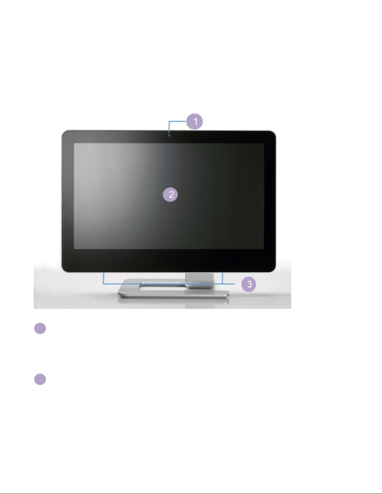
Front View
Please refer below picture showing and take note the real front view and function may differ
depend on what the model you purchased.
Webcam
The Built-in webcam is 1.0M HD pixel with digital micro phone to allow your video with
chats online.
LCD Display
(Touch function enabled with optional item)
This 21.5/23.6 inch LCD panel is LED type with high brightness and contrast
appearance. The optimal resolution is 1920 x 1080, feature edge-to-edge touch
function that enable ten-fingers-touch to enjoy your digital finger life.

3
Speakers
High definition sound quality brings you to enjoy great music world.
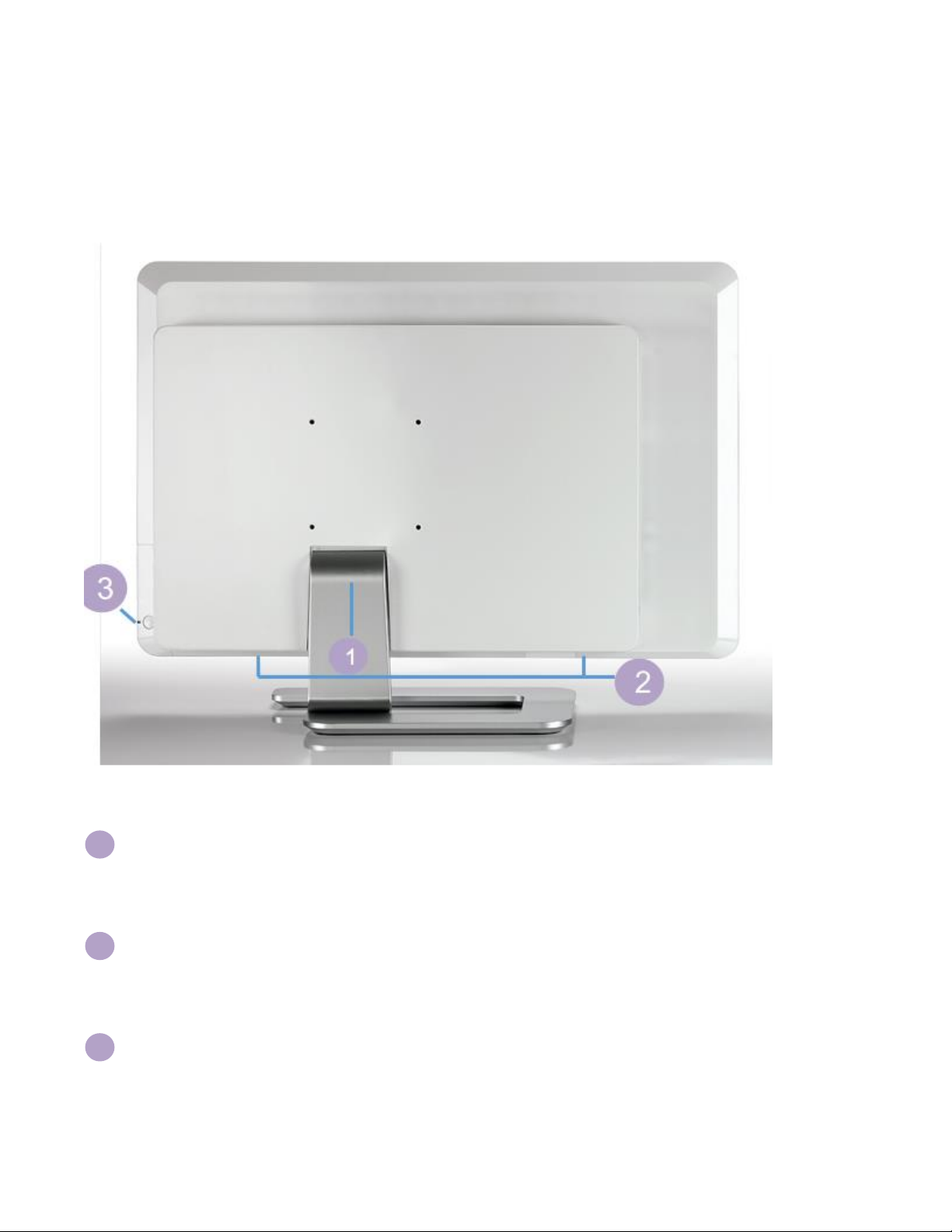
Rear View
1
2
3
Please refer below picture showing and take note the real rear view and function may differ
depend on what the model you purchased.
Stand
Adjustable stand help you to position the system upright.
Less screw design
Two screws allows you open system easier.
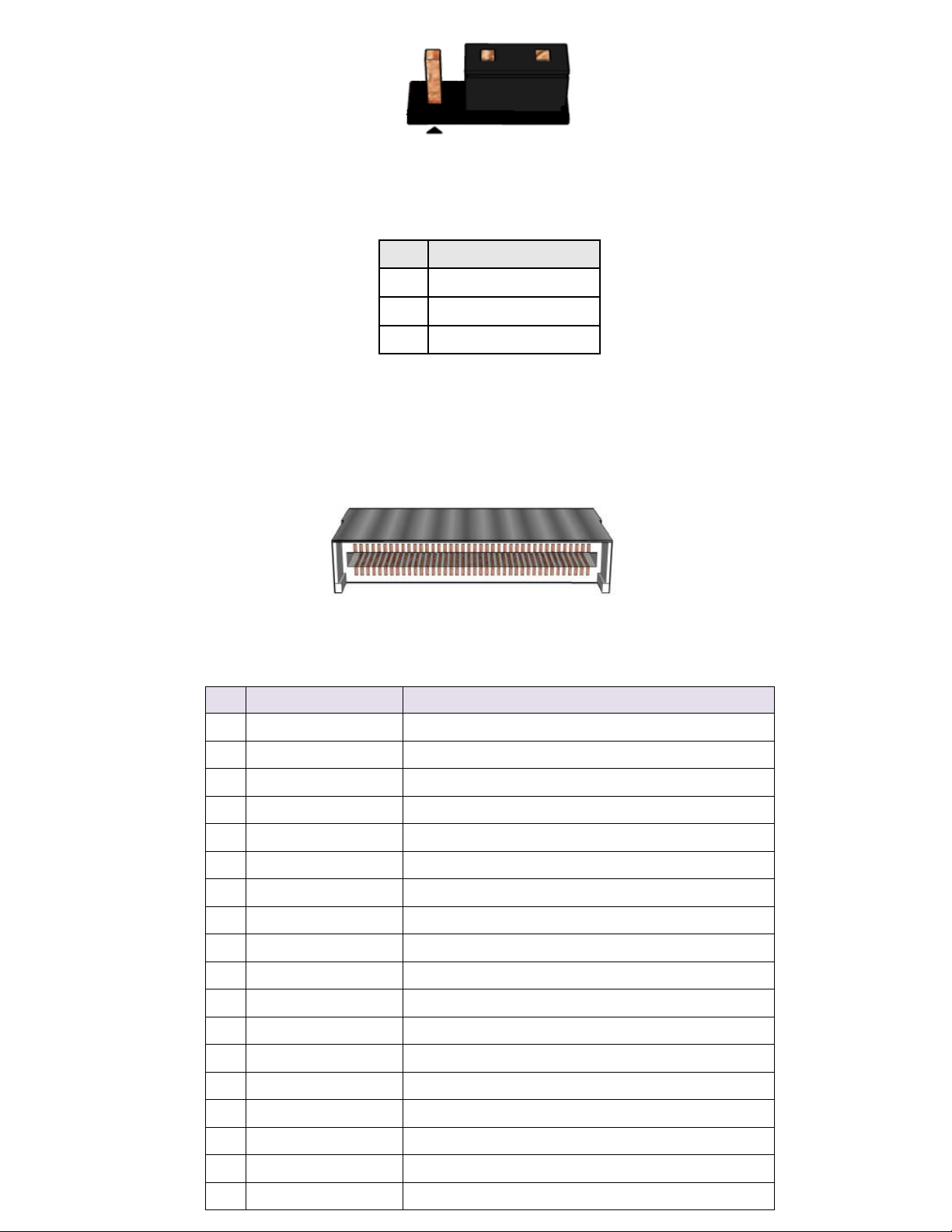
Power ON/OFF button
Power ON/OFF switch allow you turn on/off your PC.

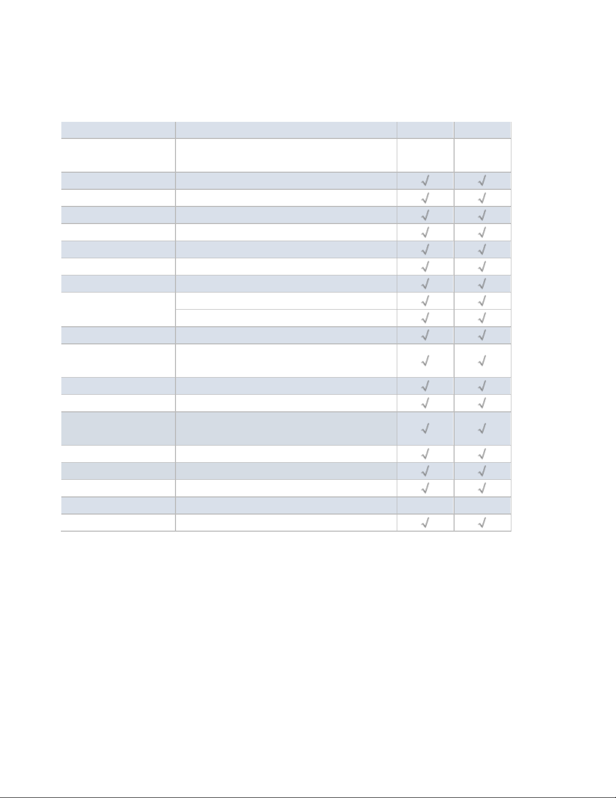
System SKU Matrix
Item
Spec
M3070
M3080
Panel
16:9, 1920 x 1080, full HD support
21.5"
(for M3070)
23.6"
(for M3080)
CPU
65W Coffee lake CPU support
Main board form factor
Thin Mini-ITX
Chipset
Coffee lake H310
Memory
x2 SO-DIMM slots, DDR4, 2666, up to 32GB
Audio
High definition audio codec
SATA HDD
2.5" / 3.5", SATA3, (HDD/SDD type support)
SATA ODD
Slim 9.5mm, tray type
Mini card
M.2 E key 2230 slot x 1, support wireless card
M.2 M key 2280 slot x 1 for SSD
Lan speed
10/100/1000 Ethernet
Webcam
1.0 HD mega pixel, HD 720p 16:9 lens with
arrary digital microphone
Speaker
High quality speaker 5W x 2
Stand type
Aluminum L-stand
System I/O ports
USB3.0 x 4, HDMI, DisplayPort, RJ45 x1, Mic-in,
Head phone out, DC inlet,
Side I/O ports
USB2.0 x2, 4-in-1 card reader
System control button
Power button, Brightness control
System Antenna
Dual Band for M.2 Wireless Card (L5 default)
TPM (Hardware TPM)
Trusted Platform Module 2.0 (optional)
Power Adapter
19V 180W

MB Information
(MB: PH12FEI)

MB Placement:

A
Front Audio Header
B
COM Port Header (RS232)
C
DMIC Header
D
PCIEx4 slot
E
MiAPI header
F
LGA1151 CPU socket
G
Dual USB2.0 Header
H
LVDS Backlight Header
I
LVDS connector
J
Front I/O Header
K
SATA
L
SATA Power
M
SATA
N
SATA
O
Dual USB2.0 Header
P
ATX 2pin
Q
ATX 4pin
R
COM Port Header (RS232)
S
COM Port Header (RS232)
T
COM Port Header (RS232/422/485)
U
RTC battery header
V
M.2 M key 2280
W
DDR4 SODIMM slot
X
M.2 E key 2230
Y
Dual USB2.0 Header
Z
System FAN Header
AA
Front SW/LEDs Header
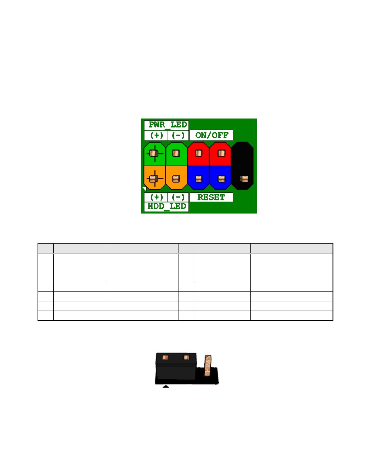
Pin
Signal Name
Description
Pin
Signal Name
Description
1
HDD_POWER_LED
Pull-up resistor (750 ) to
+5V 2 POWER_LED_MAIN
[Out] Front panel LED (Green)
3
HDD_LED#
[Out] Hard disk activity LED
4
POWER_LED_ALT
[Out] Front panel LED (Yellow)
5
GROUND
Ground
6
POWER_SWITCH#
Power button
7
RESET_SWITCH#
Reset switch
8
GROUND
Ground
9
+5V_DC
Power
10
KEY
No pin
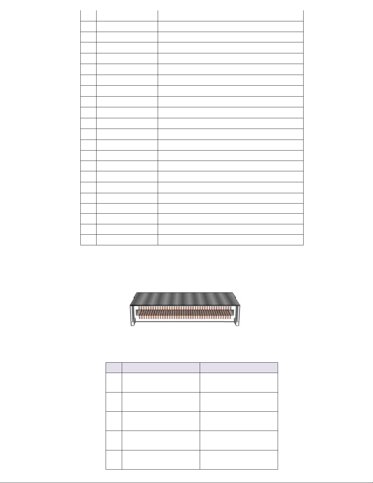
Connecting to the Internal Headers and Connectors
Front panel main header
Figure 1 : Front Panel Connector
Table 1: Front Panel Connector
Pins 1&2: jumper position for 12V
11
Pin
Signal Name
1
12VDUAL_HDMI
2
BKLT_PWR
3
+19V_A
Pin
Signal
Description
1
TD0P
LVDS Channel A diff data output - positive
2
TD0N
LVDS Channel A diff data output - negative
3
TC0P
LVDS Channel A diff data output - positive
4
TC0N
LVDS Channel A diff data output - negative
5
TB0P
LVDS Channel A diff data output - positive
6
TB0N
LVDS Channel A diff data output - negative
7
TA0P
LVDS Channel A diff data output - positive
8
TA0N
LVDS Channel A diff data output - negative
9
TD1P
LVDS Channel B diff data output-positive
10
TD1N
LVDS Channel B diff data output-negative
11
TC1P
LVDS Channel B diff data output-positive
12
TC1N
LVDS Channel B diff data output-negative
13
TB1P
LVDS Channel B diff data output-positive
14
TB1N
LVDS Channel B diff data output-negative
15
TA1P
LVDS Channel B diff data output-positive
16
TA1N
LVDS Channel B diff data output-negative
17
GND
Ground
18
3.3V/5V/12V
Selectable LCD power output
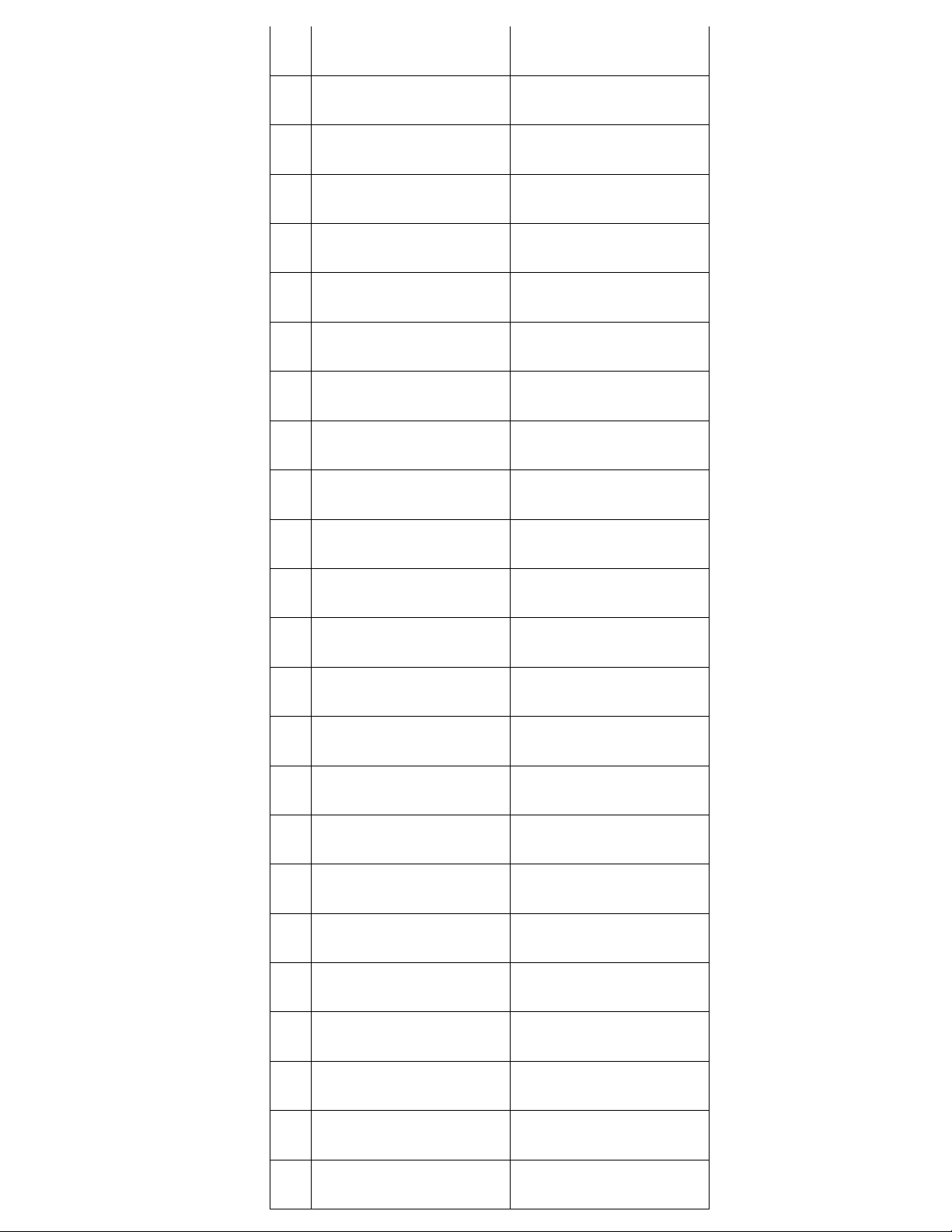
Pins 2&3: jumper position for 19V
Figure 2 : Inverter power voltage selection header signals
Table 2: Inverter power voltage selection header signals
Figure 3: LVDS Connector
12
19
3.3V/5V/12V
Selectable LCD power output
20
3.3V/5V/12V
Selectable LCD power output
21
VCC
VCC
22
NC
NC
23
VCC3
VCC3
24
CABLE_ID2
CABLE_ID2
25
GND
Ground
26
TCK0P
LVDS Channel A diff data output - positive
27
TCK0N
LVDS Channel A diff data output - negative
28
GND
Ground
29
GND
Ground
30
CABLE_ID3
CABLE_ID3
31
LVDS_DDC_SCL
LVDS_DDC_SCL
32
CABLE_ID1
CABLE_ID1
33
PS8625_BKLT_CTRL
PS8625_BKLT_CTRL
34
TCK1P
LVDS Channel B diff data output - positive
35
TCK1N
LVDS Channel B diff data output - negative
36
NC
NC
37
NC
NC
38
NC
NC
39
CABLE_ID4
CABLE_ID4
40
NC
NC
Table 3: 40-pin LVDS data header pin-out reference
Pin
Signal
Description
1
NC
NC
2
GND
Ground
3
EDP_CPU_3-
MAIN LINK
4
EDP_CPU_3+
MAIN LINK
5
GND
Ground
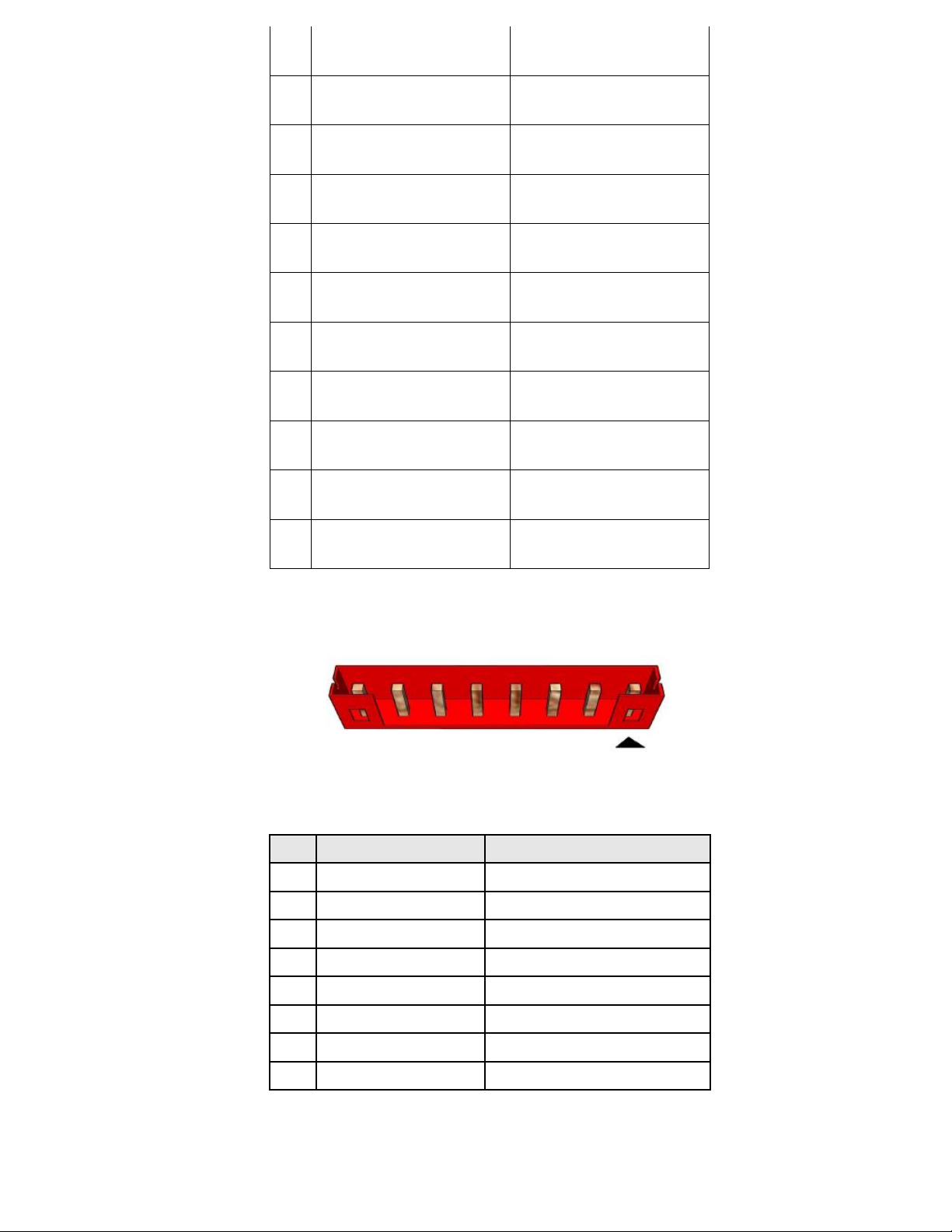
Figure 4: eDP Connector
13
6
EDP_CPU_2-
MAIN LINK
7
EDP_CPU_2+
MAIN LINK
8
GND
Ground
9
EDP_CPU_1-
MAIN LINK
10
EDP_CPU_1+
MAIN LINK
11
GND
Ground
12
EDP_CPU_0-
MAIN LINK
13
EDP_CPU_0+
MAIN LINK
14
GND
Ground
15
EDP_CPU_AUX+
Aux channel
16
EDP_CPU_AUX-
Aux channel
17
GND
Ground
18
LCD_VCC
Selectable LCD power output
19
LCD_VCC
Selectable LCD power output
20
LCD_VCC
Selectable LCD power output
21
LCD_VCC
Selectable LCD power output
22
NC
NC
23
CABLE_ID2
CABLE_ID2
24
GND
Ground
25
GND
Ground
26
GND
Ground
27
HPDET
Hot plug detection
28
GND
Ground
29
GND
Ground
14
30
CABLE_ID3
CABLE_ID3
31
GND
Ground
32
BKLT_EN
BKLT_EN
33
PCH_BACKLIGHT_PWM
PCH_BACKLIGHT_PWM
34
NC
NC
35
NC
NC
36
BKLT_PWR
Selectable BKLT power output
37
BKLT_PWR
Selectable BKLT power output
38
BKLT_PWR
Selectable BKLT power output
39
BKLT_PWR
Selectable BKLT power output
40
NC
NC
Table 4: 40-pin eDP data header pin-out reference
Pin
Signal Name
Description
1
LVDS_BKTEN_R
Backlight enable
2
LVDS_PWM
Backlight PWM control
3
12V/19V
Inverter power
4
12V/19V
Inverter power
5
GND
Ground
6
GND
Ground
7
BRIGHT_UP-
BRIGHTNESS UP
8
BRIGHT_DOWN-
BRIGHTNESS DOWN
Figure 5: LVDS inverter power header pin-out
Table 5: 8-pin LVDS inverter power header signals
15
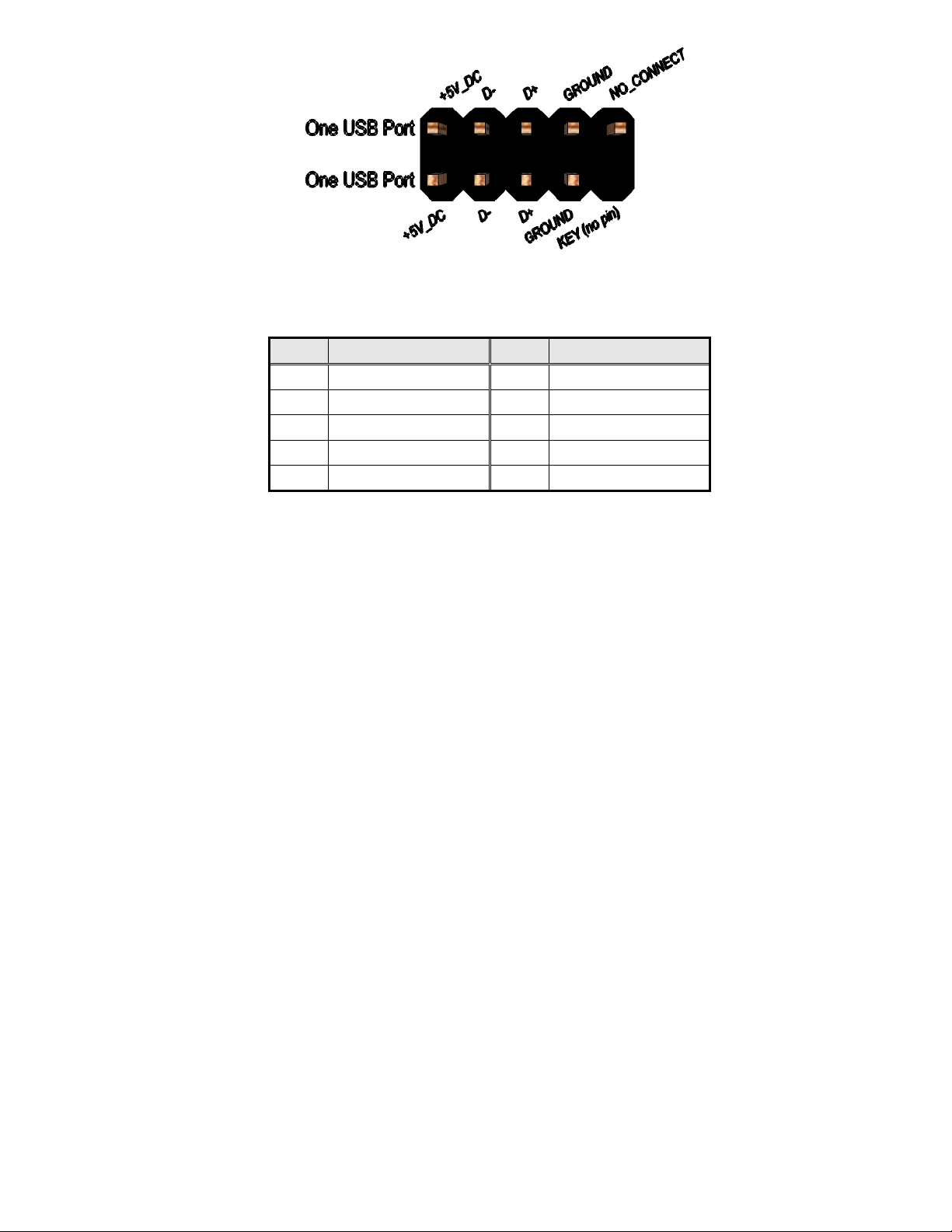
Pin
Signal
Pin
Signal
1
5V_USB
2
5V_USB
3
Data (negative)
4
Data (negative)
5
Data (positive)
6
Data (positive)
7
Ground
8
Ground
9
Key (no pin)
10
No Connect
Figure 6: Dual USB2.0 pin-out
Table 6 Dual USB 2.0 Header
16
Pin
Signal Name
Description
1
VCC
Power
2
DMIC_DATA_R
DMIC DATA
3
DMIC_CLK_R
DMIC CLOCK
4
Ground
Ground
5
KEY
NO pin
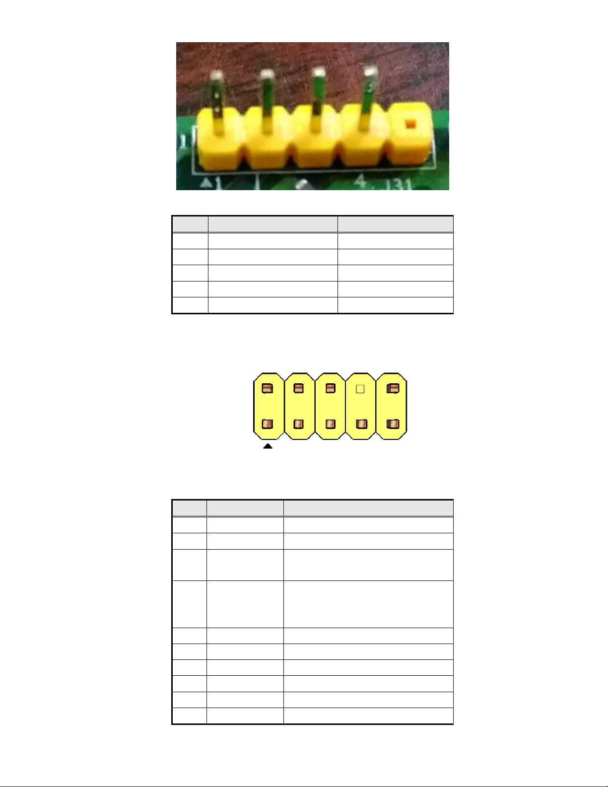
Pin
Signal Name
Description
1
MIC
Front panel microphone input signal
2
AUD_GND
Ground used by analog audio circuits
3
MIC_BIAS
Microphone power / additional MIC input
for stereo microphone support
4
Presence
Active low signal that signals bios that
an audio dongle is connected to the
analog header
5
FP_OUT_R
Right channel audio signal to front panel
6
AUD_GND
Ground used by analog audio circuits
7
Reserved
reserved
8
Key
No pin
9
FP_OUT_L
Left channel audio signal to front panel
10
AUD_GND
Ground used by analog audio circults
Figure 7: DMIC Cable pin-out
Table 7: DMIC Cable signals
Figure 8: FP Audio pin-out
Table 8: FP Audio Header

17
Pin
Signal Name
1
Front_L-
2
Front_L+
3
Front_R+
4
Front_R-
Pin
Signal Name
1
DCD
2
RXD#
3
TXD#
4
DTR
5
GND
6
DSR
7
RTS
8
CTS
9
RI
10
Key
Figure 9: Internal speaker pin-out
Table 9: Internal header signals
Figure 10: Serial port header pin-out
Table 10 Serial port header pin-out
18
Pin
Signal
1
Ground
2
+12V
3
CPU_FAN_TACH
4
CPU_FAN_CTRL
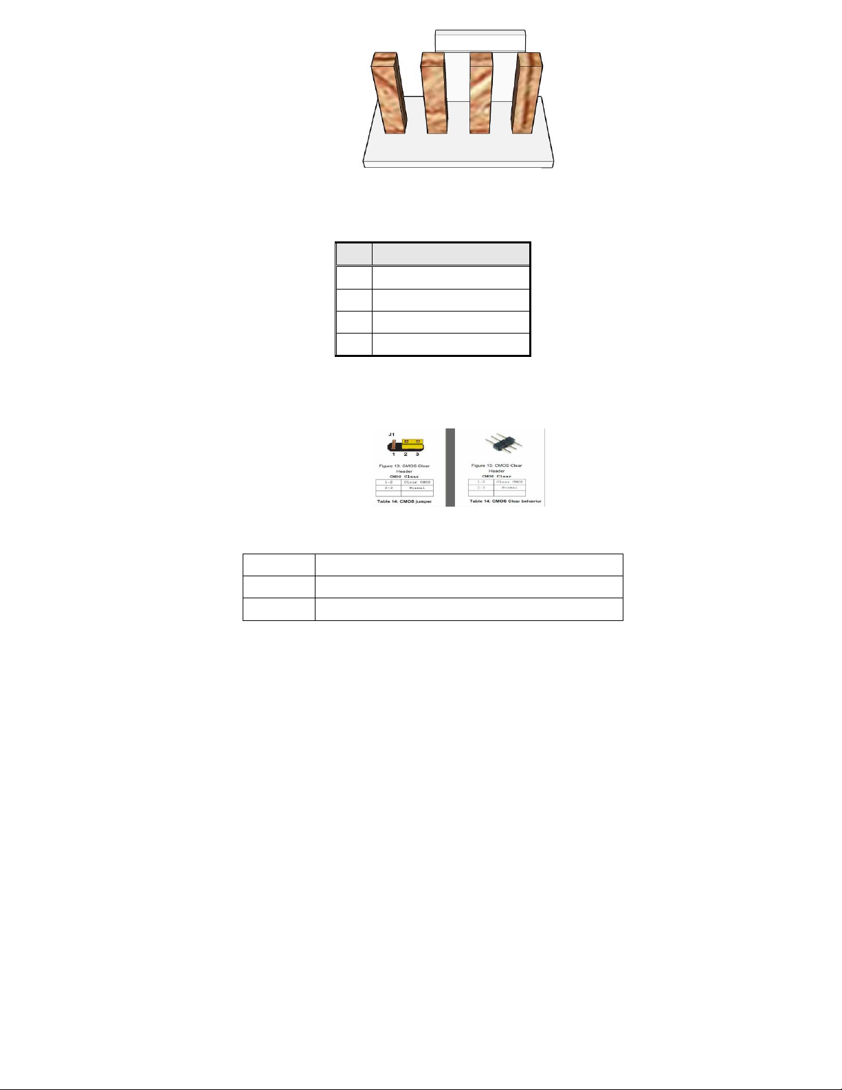
Figure 12: CMOS Clear Header
CMOS Clear
1-2
Clear CMOS
2-3
Normal
Figure 11 Processor fan header pin-out
Table 11 fan header signals
Table 12: CMOS Clear behavior
 Loading...