

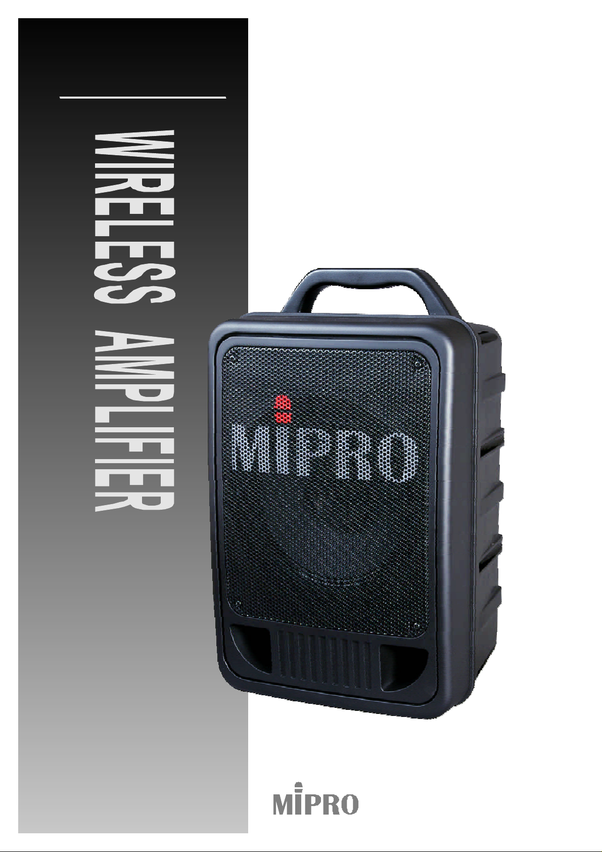
MIPRO ma705 User Manual
MA-705
InstructionManual
ELECTRONICSCO.,LTD.

ElectronicsCo.,Ltd.
Headoffice:814,Pei-KangRoad,Chiayi,600,Taiwan.
2CE161
Taipeioffice:5,Lane118,Sung-tehRoad,110,Taiwan.
Web-http://www.mipro.com.tw
E-mail:@mipro.com.tw
mipro
Taipei,
WIRELESSAMPLIFIER
OperatingManual
ThankyouforchoosingaMIPROMA-705seriesWirelessPortablePublicAddress
System.Pleasetaketimetoreadtheseinstructionscarefullysothatyoucanachieve
thebestperformancefromthesystem.
TheMA-705isaWirelessPortablePublicAddressSystem,housedinaheavy
duty,ergonomicallydesignedcase.Itoffers50Watts(RMS)highfidelityoutputand
maybeoptionedwithawiredmicrophone,uptotwowirelessmicrophones,andaCD.
TheMA705isconvenientlypoweredbybothACandDC(rechargeablebatteries)
powersupplies.Applyingthemostadvanceddesigntechniquestoeachfunctionof
MA-705makesitthehottestwirelessPAsystemonthemarket.Thecombinationof
powerful,highfidelitysoundinaflexible,lightweightpackagemakesitperfectfor
schools,placesofworship,corporatemeetings,exhibitions,aerobicclasses,andother
smalltomidsizegatheringswherePAsystemsarerequired.
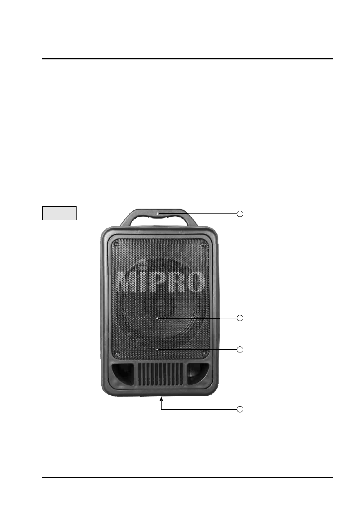
1.PARTSNAMESANDFUNCTIONS
1
Front:
FixedHandle
2
Speaker
3
SpeakerGrille
4
TripodPit
(1)FixedCarryingHandle:Foreasyportability.
(2)Speaker:Apowerful8-inchfull-rangespeaker.
(3)SpeakerGrille:Toprotectthefull-rangespeakerfromdamage.
(4)TripodPit:Suitsa35tripod.ψ
-1-
OperatingManual
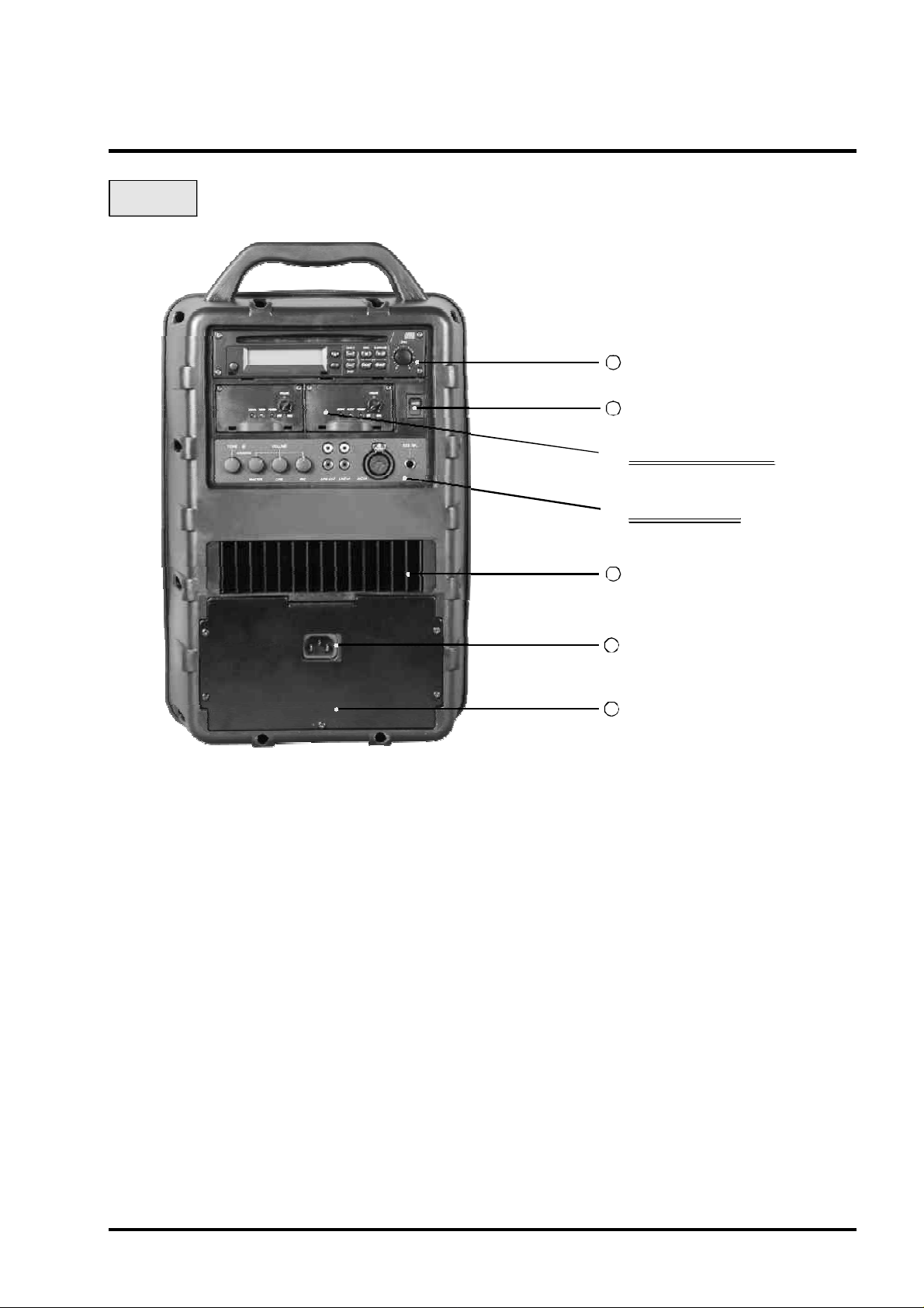
Back:
WIRELESSAMPLIFIER
5
Anti-ShockCDPlayer
6
DCPowerSwitch
A. ReceiverModules
B. ControlPanel
7
HeatSink
8
ACInputSocket
9
BatteryCover
(5)CDPlayer:Featuringananti-shockmechanism.Pleaserefertotheinstruction
manualforCDplayerthatisincludedinthepackage.
(6)DCPowerSwitch:TurnsDCpoweron/offoftheunit.Theindicatorglowswhenyou
turnthepoweron.Pleasenotethattoavoidover-dischargingorstressingbuilt-in
batteries,itisrecommendedthatyouchargetheunitimmediatelytheLEDindicator
flashes(indicatingalowbatterywarningstatus).Otherwise,theunitwillturnoff
automaticallyatapreset,lowDCpowerlimit.Normalchargingtimeisapproximately
sixhoursandabuiltinprotectioncircuitwillpreventover-charging.
(7)HeatSink:Designedspeciallytocoolthebuilt-inamplifier,pleasekeepitadequately
ventilated.
(8)ACInputSocket:Abuilt-inswitch-modepowersupplyacceptsforACpowerinputs
rangingfrom100Vto240V.
(9)BatteryCover:Toprotectthebuilt-inbatteriesandpowersupply.Ifyouneedto
changethebatteries,pleaseobservethecorrectpolarityandalwayskeepthe
batteryfull-charged.Unlessyouexperienceabatteryfailure,changingor
uninstallingbatteriesshouldnotbenecessary.Ifindoubt,pleasecontactyour
nearestserviceagentorsupplier.
-2-
WIRELESSAMPLIFIER
OperatingManual
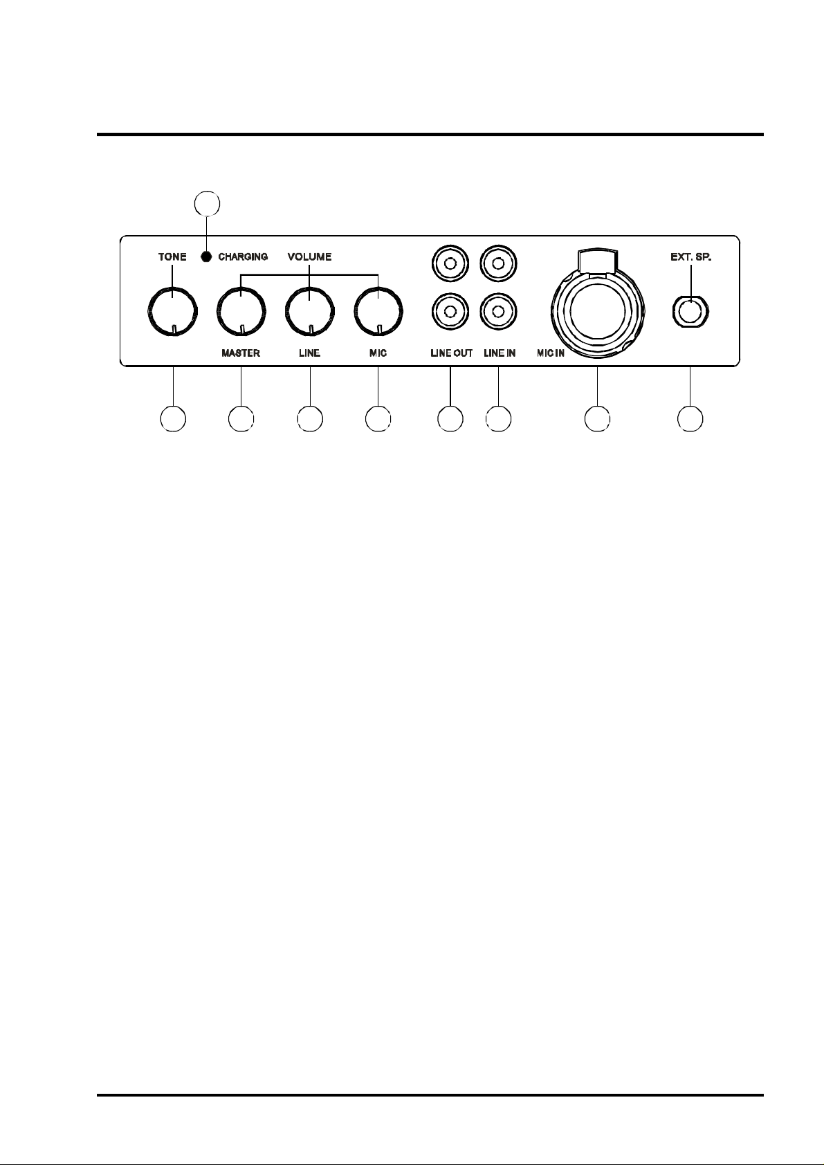
A.ControlPanel
A9
A1 A2 A3 A4 A5 A6 A7 A8
(Fig.1)
(A1)ToneControl:Turncounterclockwisetoincreasebassorturnclockwiseto
increasetreble.Setat12o'clockforaflatresponse.
(A2)MasterVolumeControl:Simultaneouslyadjuststhevolumeofallmixedaudio
inputs.
(A3)LINEINVolumeControl:ControlsthevolumeoftheLineSocket(A6).
(A4)MicInVolumeControl:Controlthevolumeofthewiredmicrophone(A7).
(A5)LineOutSocket:Stereolinelevelaudiooutput.
(A6)LineInSocket:Allowsyouuseanexternaldevicewithanunbalancedaudio
outputasaninputtotheMA-705.
(A7)WiredMicrophoneInputSocket(XLRBalanced/Phone JackUnbalanced):Allows
youtoconnectawiredmicrophonewitheitherabalancedXLRorunbalanced
phonejackconnector.
(A8)ExtensionSpeakerSocket:Connectstoan8Ohm/50Wspeaker.
(A9)ChargingIndicator:Thechargingindicatorflasheswhenthesystemischarging.
Flashingstopswhenthebatteriesarefullycharged.
B. OptionalWirelessMicrophoneReceiverModules
MIPROoffersaselectionofoptionalwirelessmicrophonereceivermodules.Each
modulehasuniquefeaturesandyoumayinstalloneortwomodulesintheMA-705.
1.MA-705-VA:VHFReceiverModule.
2.
MA-705-UA:UHFAntenna-DiversityReceiverModule.
Antenna-Diversity
-3-
WIRELESSAMPLIFIER
OperatingManual
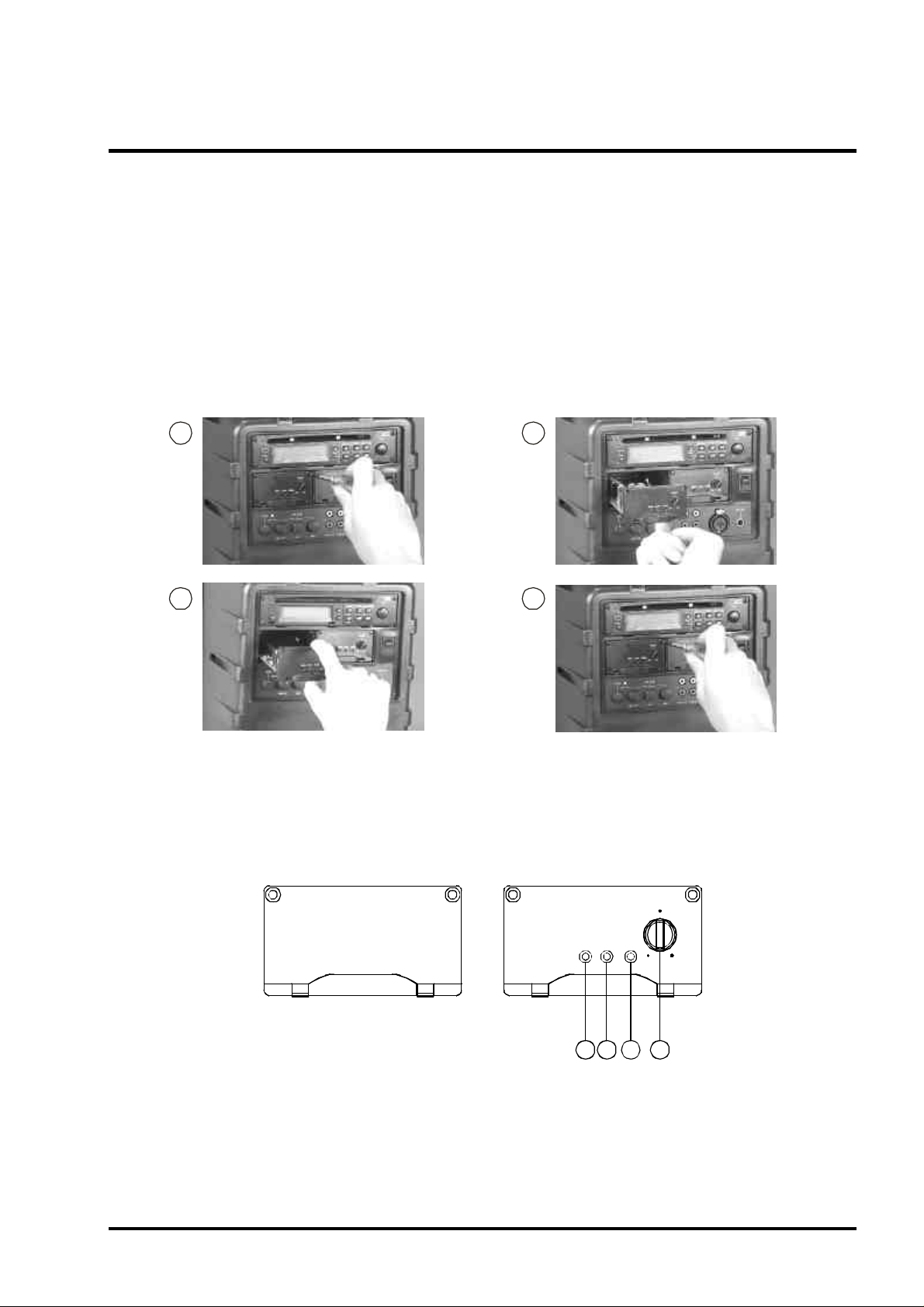
C.InstallingaWirelessMicrophoneReceiverModule:
1.UptotworeceivermodulesmaybeinstalledinaMA-705.
2.Eachreceivermoduleisequippedwith"PILOTONE"andthelatest"NOISE
LOCK"dual-squelchcircuittoeliminaterandomnoise.
3.Unscrewthetwoscrewsfromthefillerpanelandremovethefillerpanel.Insert
thereceivermoduleintotheemptyslotandpushitcarefullyintoit'smating
connector.Usethescrewsremovedpreviouslytosecurethereceivermodulein
toposition.
1
2
43
D.OperatingaWirelessMicrophoneReceiverModule
MA-705-VA/UA
VOLUME
POWERAUDIOSIGNAL
OFF MAX
C1C2C3C4
(C1)ReceiverPowerSwitchandVolumeControl:Allowsyoutoturnpoweron/offto
thereceivermoduleandadjustitsvolume.
(C2)PowerIndicator:Indicatesreceiverpowerstatus.
(C3)AudioIndicator:Indicatesthevolumelevelofthewirelessmicrophone.
(C4)SignalPresenceIndicator:ThelightturnsONwhenasignalfromthewireless
microphoneisdetected.
-4-
WIRELESSAMPLIFIER
OperatingManual
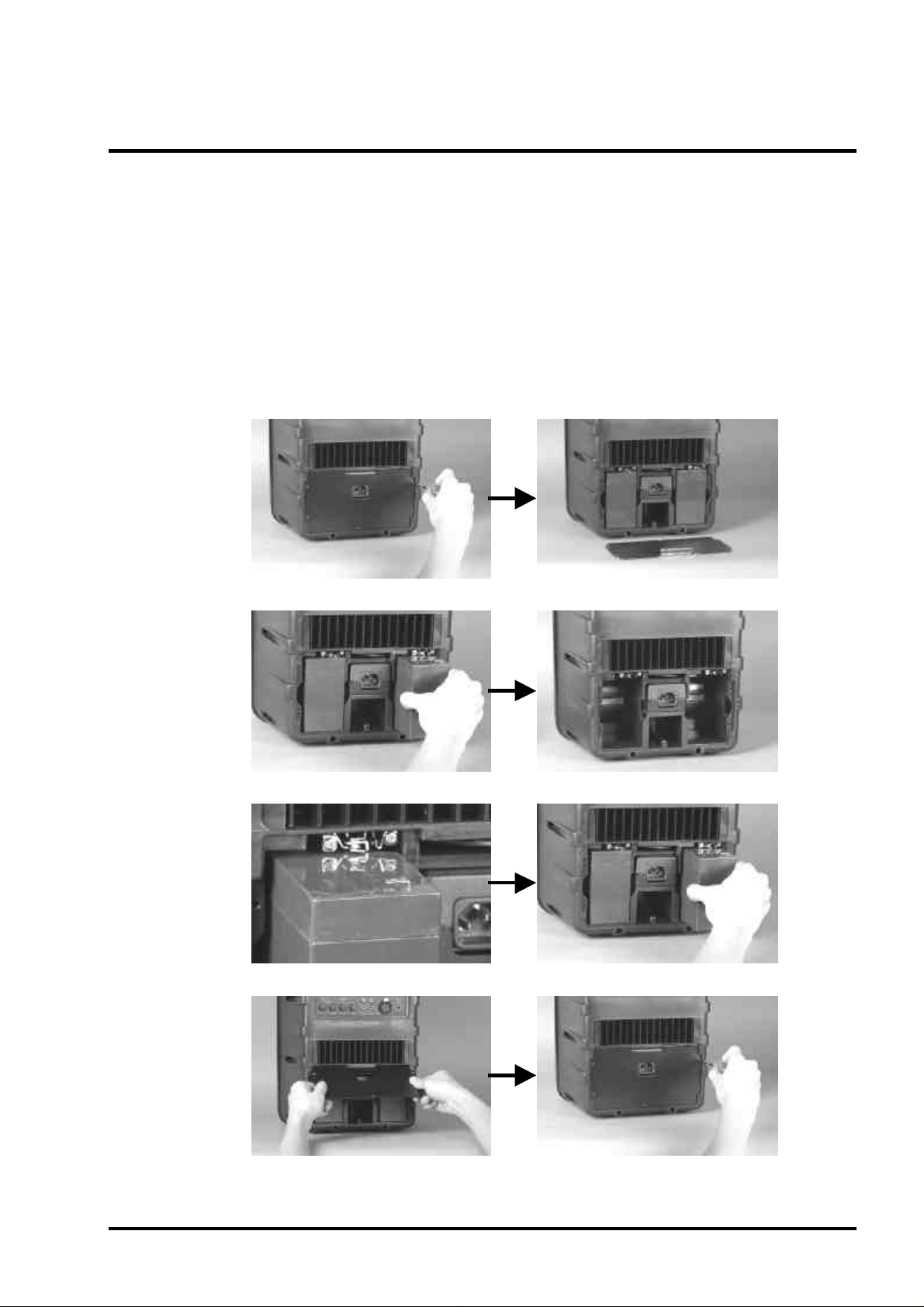
2.REPLACINGBATTERIES
A.Removethescrewsandtakeoffthebatterycover(asshowninfig.2-1)
B.Gentlyremovetheexistingbatteries(asshowninfig.2-2)
C.Slidethenewbatteriesintothebatterycompartmentbyaligningthebattery
springs,takingcaretoensurethecorrectpolarityandterminalcontact(asshown
infig.2-3)
D.Replacethebatterycoverandscrews(asshowninfig.2-4)
(fig.2-1)
(fig.2-2)
(fig.2-3)
(fig.2-4)
-5-
 Loading...