

Page 1
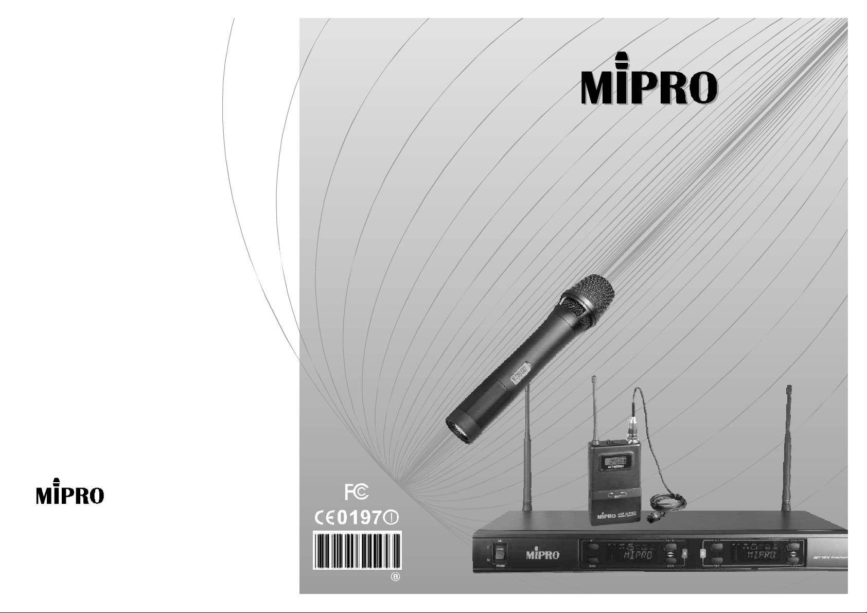
ACT-707DChannelWirelessReceiverDual
ACT-707DDualChannelWirelessReceiver
InstructionManual
ElectronicsCo.,Ltd.
Headoffice:814,Pei-KangRoad,Chiayi,600,Taiwan.
Taipeioffice:5,Lane118,Sung-tehRoad,100,Taipei,Taiwan.
Web-http://www.mipro.com.tw
E-mail:@mipro.com.twmipro
2CE150
Page 2

CONTENTS
ACTDUALCHANNELWIRELESSRECEIVER
ACTDUALCHANNELWIRELESSRECEIVER
1.INTRODUCTION
2.PARTSNAMESANDFUNCTIONS
3.INSTALLATIONOFTHERECEIVER
4.RECEIVEROPERATINGPROCEDURES
5. OPERATIONOFRECEIVERWITHLCDDISPLAYPANEL
6.COMPUTERNETWORKINTERFACEOPERATION
7. CAUTIONS
HANDHELDWIRELESSMICROPHONE
1.PARTSNAMESANDFUNCTIONS
2.BATTERYINSERTION
3. OPERATIONOFRECEIVERWITHLCDDISPLAYPANEL
1
2-3
4-5
6
7-13
14-15
15
16
16
17
1.INTRODUCTION
Thanksforchoosingthemostadvanceddualchannelwireless
microphonesystemfromMIPRO.
Pleasereadthismanualthoroughlyforcorrectoperatingandoptimal
performance.
Intoday'saudioprofessionals,thedemandforusinglotsofmulti-channel
wirelessmicrophonesystemssimultaneouslyisgreatlyincreasing.
Furthermore,theywouldliketoseeprofessionalsystemshavethecapability
ofeasyfrequencyagility,morenon-interferingchannelsandinterference-free
operation.
ACT-707DisaninternationalEIAstandard,1-rack,truediversitymetal
receiverwhichfeatures theworld'sfirstcolorLCDpaneldisplayingmultiple
statuses.Furthermore,ithasan"AutoScan"buttontoautosearchfornon-
interferencechannelswithasimpletouchofabutton.Concurrently,asimple
1-touchonthe"ACT"buttonwillthereforeprovidesrapidandprecisechannel
settingofthetransmitter,avoidingpossibleerrorsormechanicalbreakdowns.
Thissystemisperfectforsinglesystemusageunderallprofessional
applicationsasitwasbasedonyearsofexperiencesinprofessionalaudio
markettosolveissuesofquick-changeoffrequency,selectnon-interference
frequency,andavoidinterferencetomaximizeyourwirelessexperience.
Spacesaving,stableperformance,easytooperateandcouplewithunbeatable
pricesmakeitanattractivepackage.
BELTPACKTRANSMITTER
1.PARTSNAMESANDFUNCTIONS
2.OPERATINGINSTRUCTIONS
3.AF4-PININPUTCONNECTIONMETHODS
4. OPERATIONOFRECEIVERWITHLCDDISPLAYPANEL
5. BATTERYINSERTION
18-19
20
21
22
23
IncludedAccessories﹕
①×②×
Antenna2InstructionManual1
③×
PowerCable1 ④×
⑤×⑥×
AudioOutputCable1PhoneCable1
0
1
Rack-mountBracket1-pair
Page 3
ACTDUALCHANNELWIRELESSRECEIVER ACTDUALCHANNELWIRELESSRECEIVER
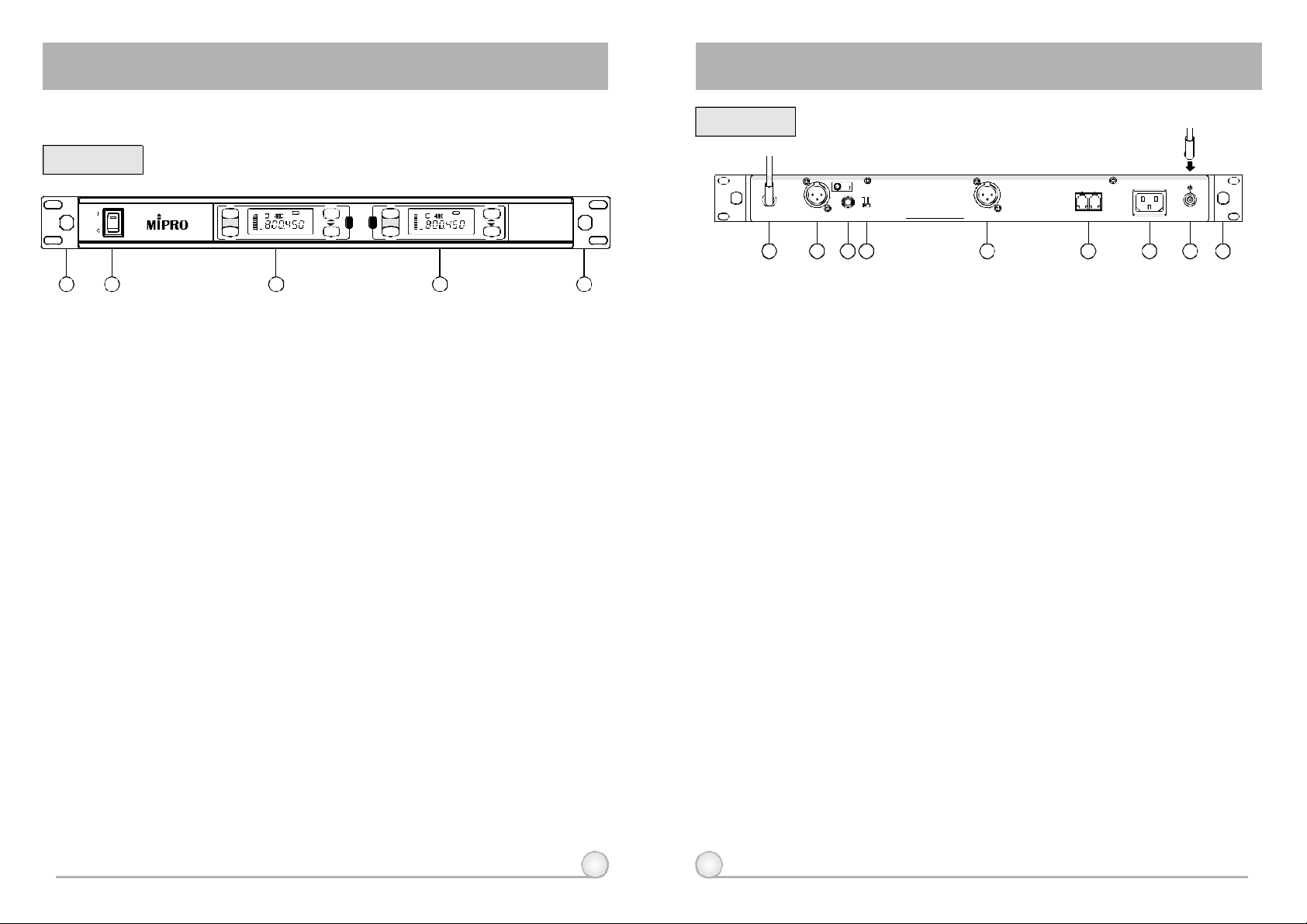
2.PARTSNAMEANDFUNCTIONS
FrontPanel:
ON
POWER
1 5
2 3 4
ACT
RF AF
BATANT
BA
MENU
GROUP
G/CH
FREQ SQ
VOL
REMONAME
MHz
SCAN
(1)FrontAntennaAInputConnector:Allowsanoptionalrear-to-front
Antennakitforfrontantennaplacement.
(2)PowerSwitch&Indicator:Whenswitchisturnedon,redindicator
illuminatestodenotenormalpowerstatus.
(3)ReceiverPanelA:ColorLCDPanelA.
(4)ReceiverPanelB:ColorLCDPanelB.
(5)FrontAntennaBInputConnector:Allowsanoptionalrear-to-front
Antennakitforfrontantennaplacement.
A B
ACT
RF AF
BATANT
BA
MENU
GROUP
G/CH
FREQ SQ
VOL
REMONAME
MHz
SCAN
ACT-707D WirelessReceiver
(Fig.1)
RearPanel:
+8VDCBIAS +8VDCBIAS
ANTENNAB
6 12
1:GND
21
+
2:HOT
3
3:COLD
-
MIC LINE
LEVELMIXOUTBALANCEDOUTB ANTENNAA
MADEINTAIWAN
BALANCEDOUTA
7 8 9 10
REMOTE
INOUT
11
AC100V~240V
13 14
(Fig.2)
(6)AntennaBinputConnector:AntennaBconnectorcanbeinstalledwith
antennadirectlyandprovidespowerforantennabooster.
(7)(10)BalancedAudioOutputJack:WithCannon/XLRtypeconnector
providesbalancedaudiooutputsignalthatmatchescapsulesensitivity.
(8)UnbalancedAudioMixedOutputJack:With1/4PhoneJack
λ
providesthemixedunbalancedaudiooutputsignalfromthisjacktothe
amplifier.
(9)UnbalancedLevelSwitch:"MIC"selectionisfor"Microphone-level"
output."LINE"selectionisfor"Line-out"leveloutput.
(11)ComputerNetworkInterfaceConnector: Networksockettoconnectto
thecomputerizedsystem-monitoringprogram.
(12)ACInputJack:Toconnect85~265VoltsACpower.
(13)AntennaAinputConnector:AntennaAconnectorcanbeinstalledwith
(14)RackmountBracket:ToinstallthereceiverintoanEIA19-inchstandard
2 3
antennadirectlyandprovidespowerforantennabooster.
rackcase.
Page 4
ACTDUALCHANNELWIRELESSRECEIVER ACTDUALCHANNELWIRELESSRECEIVER
3.INSTALLATIONOFTHERECEIVER
+8VDCBIAS +8VDCBIAS
ANTENNAB
1:GND
21
+2:HOT
-
3
3:COLD
MIC LINE
LEVELMIXOUTBALANCEDOUTB ANTENNAA
MADEINTAIWAN
BALANCEDOUTA
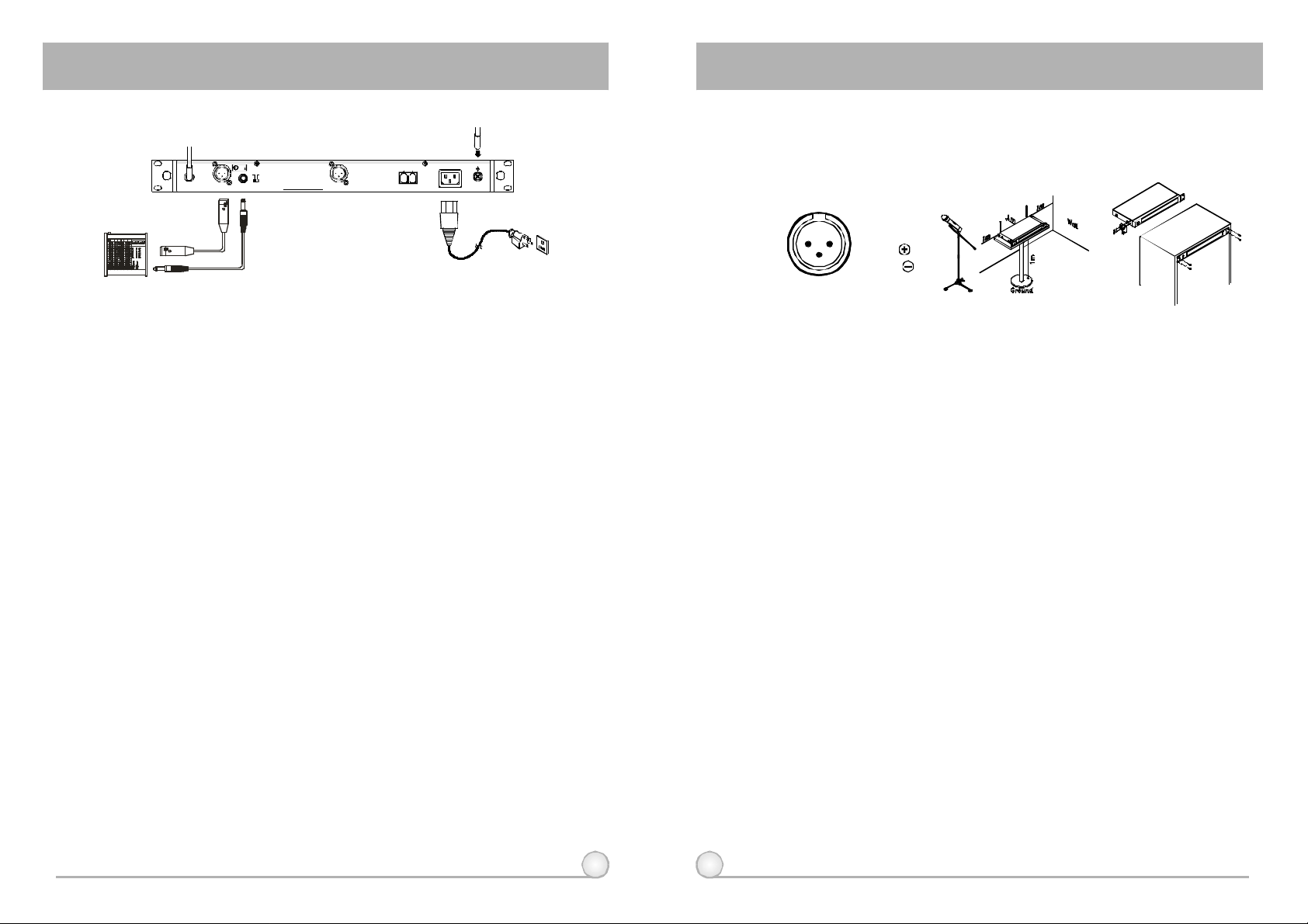
1.Install2separateantennasontheantennasockets(6),(13)ontherear
panel.Illustratedin
Fig.3.
2.PowerOutputConnection:
(a)WiththeappropriateACpowercableconnectsfromACInputJack(12)toan
ACoutletunderthemarkedvoltage85~265V,asshowninFig.5.
3.AudioOutputConnection:
(a)UnbalancedLevelSwitch(9)SettingPosition:Wheninputstheunbalanced
outputofareceiverinto"AUX-IN"inputjackofamixeroramplifieror"Electric
Guitar",switchtheLevelSwitch(9)totheright"LINE"position.Low
sensitivitymayoccurifswitchtothewrongposition.Wheninputthe
unbalancedoutputofareceiverintothe"MIC-IN"inputjackofamixeror
amplifier;switchtheLevelSwitch(9)totheleft"MIC"position.Overload
distortionmayoccurifswitchtothewrongposition.Whenusingelectricguitar,
don'tuse"MIC"positionasitmayhavegeneratedinsufficientlevel.
(b)UnbalancedOutput:Usingaudiooutputcableattachedwith"PHONEPLUG"
type,connectoneendfromtheunbalancedoutputjack(8)ofthereceiver,
andtheotherendtothe"LINE-IN"inputjackoftheamplifier,asshowninFig.
3.
(c)BalancedOutput:Usingaudiooutputcablesattachedwith"XLR"or"Cannon"
type,connectoneendfromthebalancedoutputjacks(7)ofthereceiver,and
theotherendtothe"MICIN"inputjackofthemixeroramplifier,asshownin
Fig.3.(Thecharacteristicofthe3-pinconnectorisasshowninFig.4
(d)GuitarOutput:Usingaudiooutputcableattachedwith"PHONEPLUG"type,
plugoneendfromtheunbalancedoutputjackofareceiver,andtheother
endtotheinputjackofaguitaramplifier.SwitchtheLevelSwitch(9)to
"LINE"position.
AC100V~240V
REMOTE
INOUT
(Fig.3)
(d)GuitarOutput:Usingaudiooutputcableattachedwith"PHONEPLUG"type,
plugoneendfromtheunbalancedoutputjackofareceiver,andtheother
endtotheinputjackofaguitaramplifier.SwitchtheLevelSwitch(9)to
"LINE"position.
1:GND
21
2:HOT
3
3:COLD
(Fig.4)
(Fig.6)(Fig.5)
4.Toensurebestreceptionpossible,receivermustbeinstalledatleastone
meteraboveground.Inaddition,thedistancebetweentransmitterand
receivermustbemorethanonemeterandawayfromnoise.(Showsin
)Fig.5.
5.Withrackmountkit,receivercanbeinststalledonthestandard19-inch
rackcase.(ShowsinFig.6.)Onecanalsopurchasefrontantenna
convertingkitsfromyourlocaldealer.Wheninstallingfrontantenna
convertingkits,removeplugsfrom4pre-drilledopenings.Then,install
theantennabaseoftheconvertingcableonthepre-drilledopeningfor
antenna.Finally,installantennasdirectlytotheantennabasesto
increasereceivingefficiencyofantennas.
4 5
Page 5
ACTDUALCHANNELWIRELESSRECEIVER ACTDUALCHANNELWIRELESSRECEIVER
4.RECEIVEROPERATINGPROCEDURES
1.Turnvolumecontrolsofthemixerinusetoaminimumsettingbeforeturn
onthemicrophonesortransmitters.Afterswitchesonthereceiver,the
powerswitchredindicatorilluminatestodenotenormalpowerstatus.
2.Undernormalcircumstances,theRFindicatorlightsupwhena
microphoneortransmitteristurnedonnearthereceivertoindicatethe
receiverisreadyfornormaloperation.Oncesoundstothemicrophone
andtheAFindicatorswillglowaccordingtothestrengthofsoundlevel.
IfnoLEDglowsornosoundoutputs,thesystemisnotfunctionproperly,
thusitmustbechecked
3.Themicrophoneoutputlevelonlyneedstobeadjustedattheamplifieror
mixer.Noneedtoadjustatthereceiveritself.
5.OPERATIONOFRECEIVERWITHLCDDISPLAYPANEL
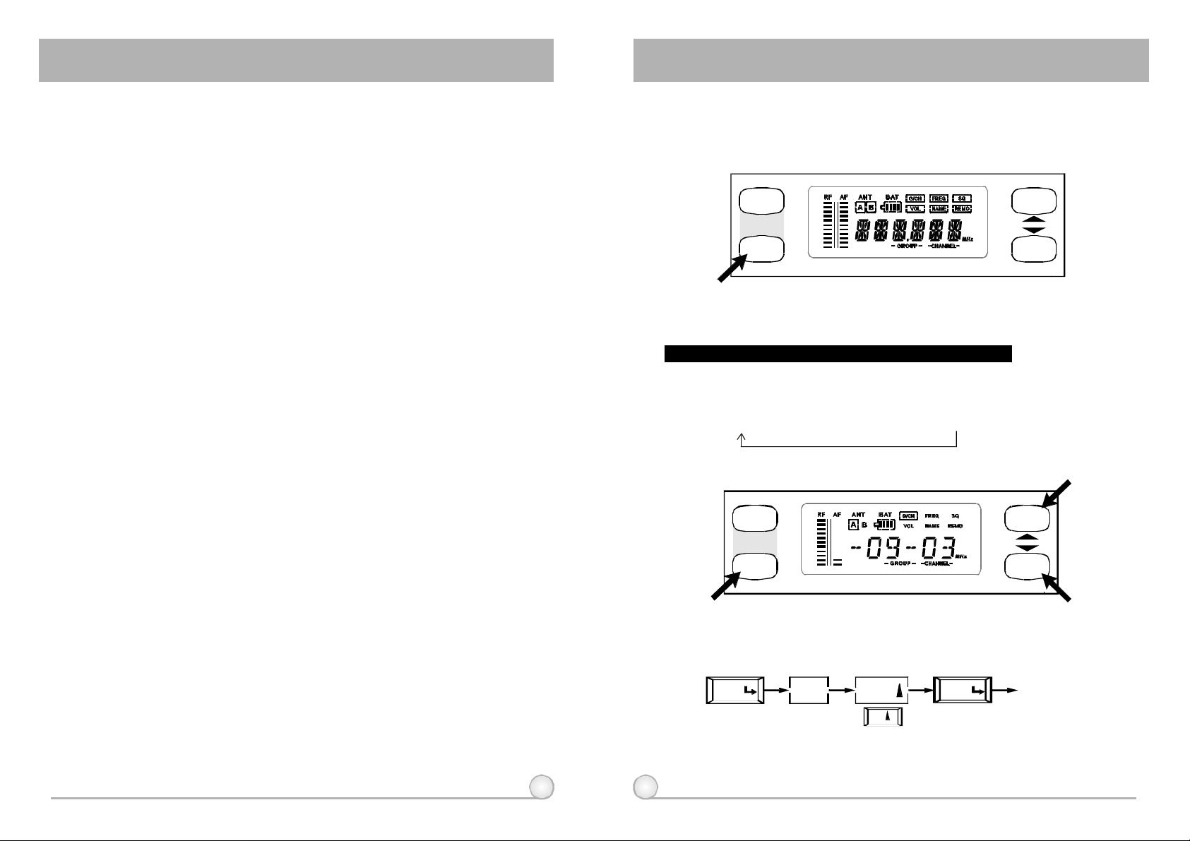
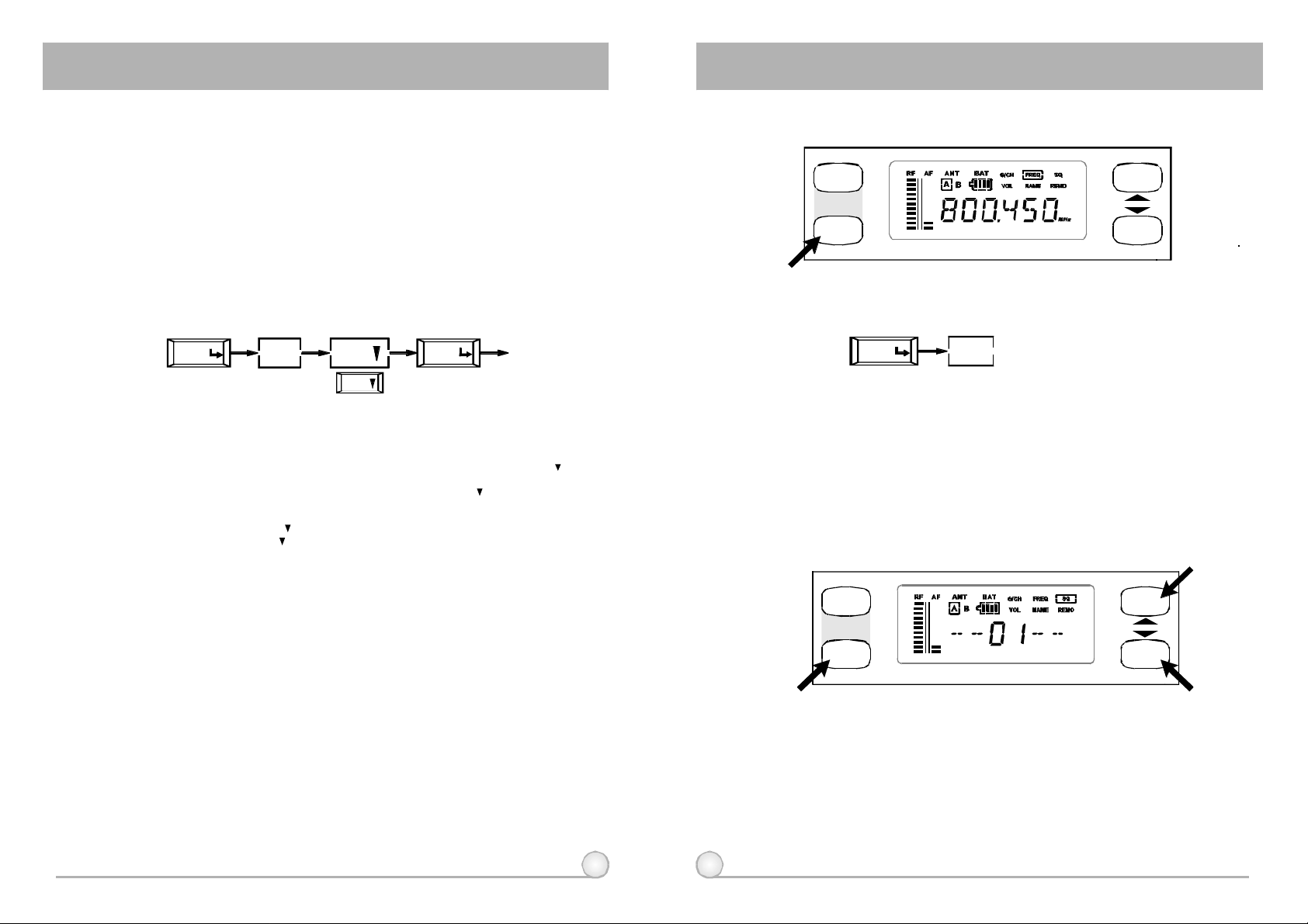
1.FullDisplayOfLCDScreenAndLocationsOfButtons
ACT
MENU
2.DesignationsOfButtonsAndFunctions
MENU:Enableusertoselectfromonefunctiontotheother
"MENU"buttonallowsusertoselectamong6options(inthesequence
showingbelow)thateachissurroundedinasquareframeandshownonthe
upperhalfofLCDdisplay.Detailfunctionsandoperationsareasfollows.
G/CHFREQSQVOLNAMEREMO→ →→→→
(1)G/CH:IndicatesorsetupsthereceiverGROUPandCHANNEL.
ACT
GROUP
SCAN
GROUP
6 7
MENU
A.OpeartionofsettingGROUP:
MENU
G/CH
GROUP
UP
SCAN
EXITMENU
Save
Page 6
ACTDUALCHANNELWIRELESSRECEIVER ACTDUALCHANNELWIRELESSRECEIVER
B.OperatingexplanationofsettingGROUP:
A.Press"MENU"buttononce,select"G/CH"blockfromthebelowlineofLCDview
wheredisplaysahorizontalbarandtwonumbersthatrepresentsgroup&channel
accordinglyfromlefttoright.
b.Press"GROUP"buttononce,thentherepresentedgroupnumberwillstartflashing
meaningthesystemisatastatusofwaitingforsetting.Pressthebuttonagain,the
groupnumberwillbechangedfollowinganincreasingcirclerule.Atthesametime,
channelnumberwillchangetothelastchannelofselectedgroup.Whenholding
"GROUP"button,thegroupnumberwillcontinuetochangeuntil"GROUP"button
isreleased.Press"MENU"or"SCAN"buttononcetostopflashingandlockthe
groupyoudesiretosetup.
C.OpeartionofsettingCHANNEL:
G/CHMENU SCAN
DOWN
MENU
Save
EXIT
D.OperatingexplanationofsettingCHANNEL:
Similarly,press"MENU"buttononce,select"G/CH"blockandpress"SCAN"
buttononce,thenthetwonumbersontherightsideofbelowlineofLCDwillstart
flashingwhichmeansastatusofwaitingforsetting.Press"SCAN"buttonagainthe
receiverwillstopatanon-interferedchannelnumberautomatically.Incaseofall
channelsinthedesiredgroupareinteferedandcan'tstopscanning,youcanchangeto
anothergroup.Pressthe"SCAN"buttonagainorholditwillkeepscanningand
continuetochangeuntil"SCAN"buttonisreleased.Press"MENU"buttononcetolock
thechannelyoudesireto setup,andchannelnumberwillbesetandstopflashing.
E.OperatingexplanationofsettingLOCKAndUNLOCK:
(2)FREQ:Indicatesthefrequencythatiscurrentlyinuse.
ACT
MENU
GROUP
SCAN
A.OperatingProcedures.
FREQMENU
B.HowtoOperate?
a.Afterpush"MENU"buttonandselectthe"FREQ"frame,itwillshowthefrequency
thatissetundertheGROUPandCHANNELthatonehadselectedpreviously.
B.Theoperationonlyfordisplayingfrequency,notforthefunctionofchanging
frequency.
(3)SQ:IndicatesorsetupstheSquelchlevel.
ACT
GROUP
A.Incaseyouwanttolockallsettingfunctionsontheoperatingpanelandavoid
generatingerroroperations,holding"MENU"buttonmorethan3secondsuntilthe
word"LOCK"showedontheLCD,thenallthebuttonswillbeinactiveexcept"ACT"
button,whichmeansthesettingofthepanelisatthelockingstatus.
b.Incaseyouwanttounlockthesettingofpanel,holding"MENU"buttonmorethan
3secondsuntiltheword"UNLOCK"showedontheLCD,thenthelockedsetting
willbereleasedaccordingly.
8 9
MENU
SCAN
Page 7
ACTDUALCHANNELWIRELESSRECEIVER ACTDUALCHANNELWIRELESSRECEIVER
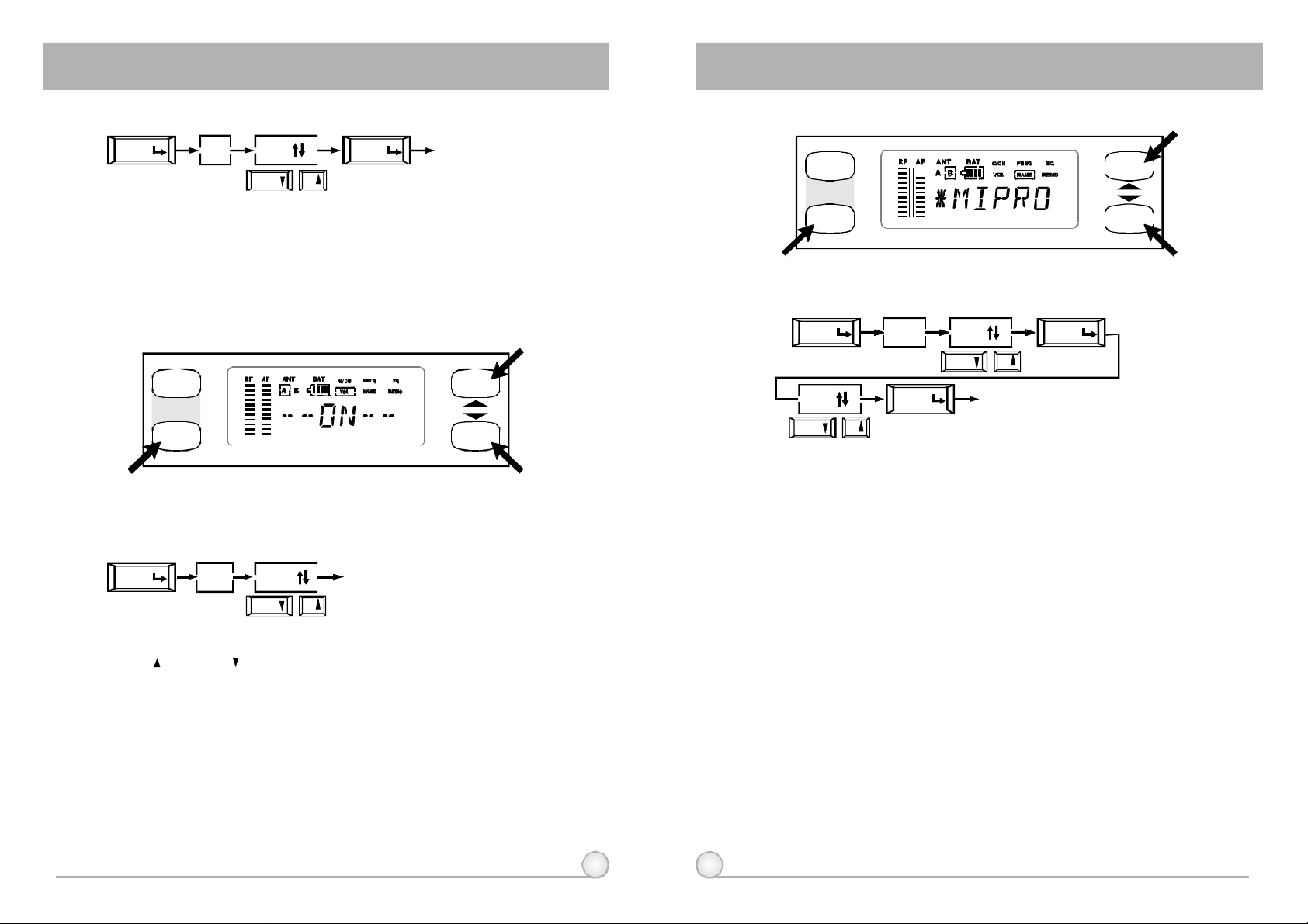
A.OperatingProcedures.
MENU
B.HowtoOperate?
a.Usercansetthesquelchlevelwithintherangeof01-99.
b.Tosetthesquelchlevel,simplybypushingthe"UP"or"DOWN"buttonandconfirm
themodificationbypushing"MENU"button.
c.Thebiggerthesettingnumber,thelowerthesensitivity.
(4)VOL:IndicatesVolumeLevelisatOnorMuteposition.
ACT
MENU
SQ
01
DOWN UP
Save
EXITMENU
GROUP
SCAN
Theoperationprovidsmutecontrolswitch
A.OperatingProcedures.
MENU
B.HowtoOperate?
Push"UP"or"DOWN"Buttonallowsonetoswitchvolumeto"ON"or"Mute"status.
VOL
MUTE
DOWN UP
EXIT
(5)NAME:Indicatesorsetupsthenameofcurrentchanneluser.
ACT
MENU
A.OperatingProcedures.
MENU
A
DOWN UP
B.HowtoOperate?
a.Maximum6charactersareallowed(SelectfromcapitalizedEnglishletter,numbers,
+-x/,andspace).
b.Push"UP"or"DOWN"buttonintosetupmodeandthecharacteronthefarleftwill
startblinking.(Therewillbenoblinkingifthereisnocharacterinthespecificspace).
c.Push"UP"or"DOWN"buttontoselectdesiredcharacterandconfirmbypushing
the"MENU"button.Onceconfirmed,thenextcharacterwillstartblinkingandready
forsetup.
d.RepeatstepcuntilALL6charactersareset.
NAME
MENU
Save
A
DOWN UP
EXIT
MENU
NEXT
GROUP
SCAN
C.CAUTIONS:
AFbarandAnt.A,BofLCDpanelwillnotdisplayedwhenthereceivermoduleis
atMutestatus.ToascertainifreceiverisatMutestatus,pressMenukey,select
Volume.IfLCDindicates"Mute"itisaMutestatus.IfLCDindicates"On"audiois
operatingnormally.
10 11
Page 8
ACTDUALCHANNELWIRELESSRECEIVER ACTDUALCHANNELWIRELESSRECEIVER
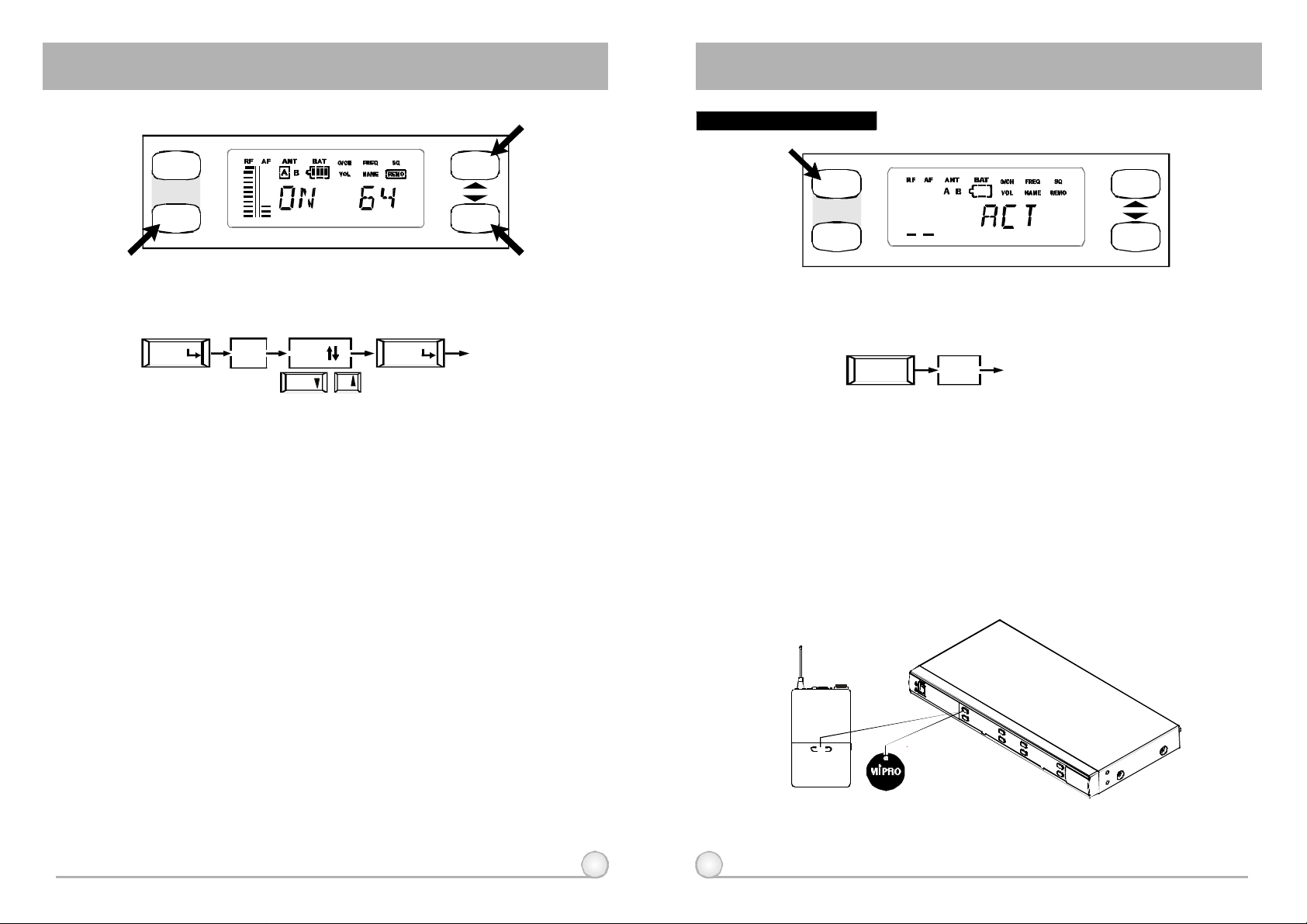
(6)REMO:Indicatesorsetupthereceiveraddressandstatusofremotecontrolling.
ACT
MENU
GROUP
SCAN
A.OperatingProcedures.
MENU
REMO
64
DOWN UP
save
EXITMENU
B.HowtoOperate?
a.ACT-BUSinterfaceisadaptedforMIPROWirelessReceiverModule.WithMIPRO
InterfaceConverterandMonitoringSoftware,upto64receivermodulescanbe
remote-controlledsimultaneouslyviaaPC.
b.Addresscanbesetwithintherangeof01-64.Underremotecontrolmode,each
receivermoduleMUSThasitsownaddress.If2differentreceivermodulesare
usingthesameaddress,itwillcauseconflictionandresultinmonitoringerror.
However,ifnotunderremotecontrolmode,operationwillremainnormalevenif2
differentreceivermodulesareusingthesameaddress.
c.Inremotecontrolmode,"ON"willbeshownintheLCDdisplaypanelandthe
numbernexttothemessageistheaddressofthereceivermodule.However,
"OFF"willbeshownisthesystemisnotremotelylinkedtothePC.
d.Push"UP"or"DOWN"buttontochangereceiveraddressandverifybypushingthe
"MENU"button.
OperationofACTFeature:
ACT
MENU
A.OperatingProcedures.
B.HowtoOperate?
a.AtLCDpaneldisplays"Group"and"Channel"modekeystroke"ACT"
button.ACTmodeisactivatedwhen"ACT"wordappearsonthe
LCDpanel.
b.Movemicrophonetowardtoreceiverwithinthedistancearoundcm,
andfacethe"ACT"markedsideonthemicrophonetothe"ACT"
buttononthepanelofreceiver,seebelowfigure.
c.ACTfunctionwillreleaseautomaticallyoncethetransmitterchannelis
lockedon.Simultaneously,"Group"and"Channel"modewillbe
backshowingontheLCDpanel.Bothtransmitterandreceiver
shouldshowthesame"Group"and"Channel".Thisindicates
transmitterfrequencyset-upissuccessful.Ifunsuccessful,repeatstep
"A".
ACT EXIT
ACT
GROUP
SCAN
30
12 13
ACT
Page 9
ACTDUALCHANNELWIRELESSRECEIVER ACTDUALCHANNELWIRELESSRECEIVER
6. COMPUTERNETWORKINTERFACEOPERATION
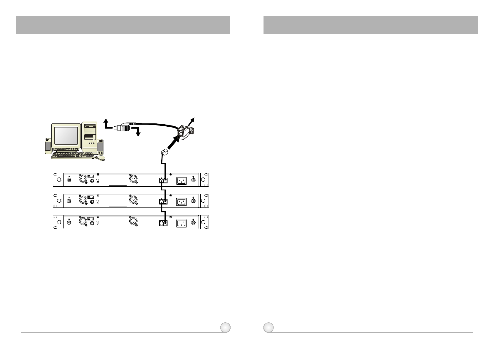
1.Exceptforreceivermodule,bothreceiverwithLCDdisplayhavethemost
advancefunctionofcomputer-network-interfacedcontrollingsystem.
2.WiringInstruction
① Connectthenetworkinterfaceremoteconnector(11)onthebackofthe
receivertotheinterfaceconverter(requiresatleast2linkingcablesforeach
pairing).Then,useRS-232cableconnectstheconvertertotheRS-232COM
PORTonthecomputer.
RX1
RX2
PC
TOPCKEYBOARDCONNECTOR
TOKEYBOARD CONNECTOR
+8VDCBIAS +8VDCBIAS
ANTENNAB
+8VDCBIAS +8VDCBIAS
ANTENNAB
1:GND
+
21
2:HOT
3:COLD
-
3
MIC LINE
LEVELMIXOUTBALANCEDOUTB ANTENNAA
MADEINTAIWAN
1:GND
21
+2:HOT
3
3:COLD
-
MIC LINE
LEVELMIXOUTBALANCEDOUTB ANTENNAA
MADEINTAIWAN
BALANCEDOUTA
BALANCEDOUTA
TOPCRS-232COMPORT
CONVERTER
AC100V~240V
REMOTE
INOUT
AC100V~240V
REMOTE
INOUT
④⑤Thissystemcanconnectupto64receiverforsimultaneousoperation.
Thoughlongerthedistanceis,worsethestabilitywillbe;nevertheless,the
networkconnectingcablecanstilloperatewhileitis300meterslong.
However,itisourrecommendationtokeepthecableunder100meterslong
toensurehigh-speedtransmission.
7.CAUTIONS
1.WhenusingDCpowersupply,pleasebeawareoftheoperatingvoltage.
Firstofall,pleasemakesureminimumof12voltscanbeobtainedfor
functionproperly.However,thepowersupplyshouldnotexceedits
maximumcapacityof15volts.Whenthesupplyvoltageismorethan15
volts,thesystemwillsuffersevereinternaldamage.Itispreferredthe
powersourceisfromaregulatedpowerwiththeminimumcurrentof1A.
2.UseonlyMIPROstandardantennatoensurethesensitivityofthe
receiver.
3.Antennasockethas8-voltsDCpowersupply;pleasedonotshortthe
circuitofthispart.
RX3
+8VDCBIAS +8VDCBIAS
ANTENNAB
1:GND
21
+2:HOT
3
3:COLD
-
MIC LINE
LEVELMIXOUTBALANCEDOUTB ANTENNAA
MADEINTAIWAN
BALANCEDOUTA
AC100V~240V
REMOTE
INOUT
(Fig.7)
②③Pleaseconnectoneendofthephonecable(included)toremoteconnector's
"OUT"jack(11)onthebackofthefirstreceiverandconnecttheotherendof
cabletoremoteconnector's"IN"jack(11)onthebackofsecondreceiver.
(ShowsinFig7.)Continuesuchparallelconnectionwithremainingreceivers.
Onceallreceiversareparallelsconnected,connectaphonecablefrom
remoteconnector's"IN"jack(11)onthebackoffirstreceivertoMIPRO-DV
converter.
Thisinterfacesystemadaptsparallelconnection.Therefore,ittakesonly2
linkingwirestocompletetheconnectiontotheconverterofthewholesystem.
14 15
Page 10
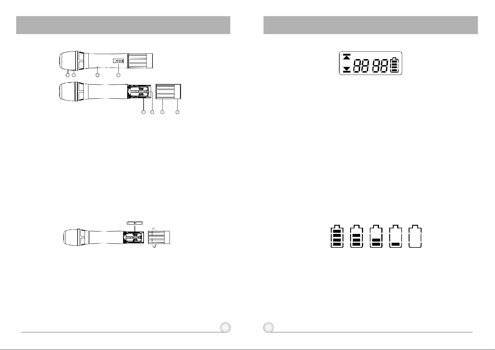
HANDHELDWIRELESSMICROPHONEHANDHELDWIRELESSMICROPHONE
1.PARTSNAMESANDFUNCTIONS
GROUP
CHANNEL
BAT
1 3
2
1.Grille:Protectscartridge,prevents"POP"noiseandpreventsmicrophone
fromrollingwithpolygonalshape.
2.ColorRing:Forfrequencydifferentiation.
3.Housing:Upperportiontobeconnectedtoacapsulemoduleandbattery.
Internally,itholdstransmitterPCB.
4.FunctionsofLCDDisplay
5.BatteryCompartment:Designedtoaccommodatetwo1.5V(AA)batteries.
6.BatteryCap:Coversbatteryinthebatterycompartment.
7.Anti-rollRing:Forfrequencydifferentiation.
8.ACTSignalReceptor:ReceivingACTsignalandadjustingfrequency
automatically.
4
5
768
(Fig.1)
3. FUNCTIONSOFLCDDISPLAY
GROUP
CHANNEL
ERR
1.ERRMessage:When"ERR"appears,itmeans"OperationError".Pleaserefer
tothefollowingcodestodiagnosewhicherroryouareexperiencing.
ERRno01EEPROMisnotbeingprogrammedorinternaldataerror.
ERRno02Fortestingonly.
ERRno03Thefrequencyyouareabouttoprogramintothesystemexceeds
→
→
→
microphone'supperlimit.(Atthistime,microphoneisstill
operatableandthefrequencyremainsunchanged.Toclearthe
"ERR"messageinLCDdisplay,simplyturnoffthepowerand
switchbackon.)
ERRno04Thefrequencyyouareabouttoprogramintothesystemisbelow
→
microphone'sfrequencylowerlimit.(Atthistime,microphoneisstill
operatableandthefrequencyremainsunchanged.Toclearthe
"ERR"messageinLCDdisplay,simplyturnoffthepowerand
switchbackon.)
2."Group"&"Channel":Whenbothitemsareshown,theyindicatethattheuser
iscurrentlyusingthepre-programmedfrequencyinthereceiver.
3."Channel"Only:If"Channel"istheonlyitemshowninthedisplay,itindicates
theuserisusingthepersonalizedfrequency.
BAT
2.BATTERYINSERTION
(Fig.2)
1.Unscrewbatterycap(6)inacounter-clockwisedirection.
2.Inserttwo1.5V(AA)batteriescorrectlyintothebatterycompartmentwith
thepositivepole(+)pointsatthemicrophonecapsule.Then,screwthe
batterycap(6)backtomicrophoneasshowninFig.2.
PS:Whenthemicrophoneisnotinuse:
Makesurethepowerofthemicrophoneisoff.Ifthemicrophonewillnot
beusedforsometime,pleaseremovethebatteriesfromthebattery
compartmenttoavoidbatteryleakageandresultindamagedbattery
springsandcircuit.Ifarechargeablebatterywasused,takeitoutand
rechargeit.
4.BatteryStatus:
100% 80% 40% 10% 0%
BatteryStatus:Whenthebatteryhaslessthan10%powerremaining,batteries
mustbereplaced.Ifundervoltagecontinues,LCDwillshow"PoFF"andshutdown
thesystemtoavoidbatterybeingover-discharged.
5.SwitchOff:
Whenswitchthepowerknobto"Off"position,LCDwillshow"PoFF"first.
Then,thesystemiscompletelyshutdownandnofurthermessagewillbe
displayed.
16 17
Page 11
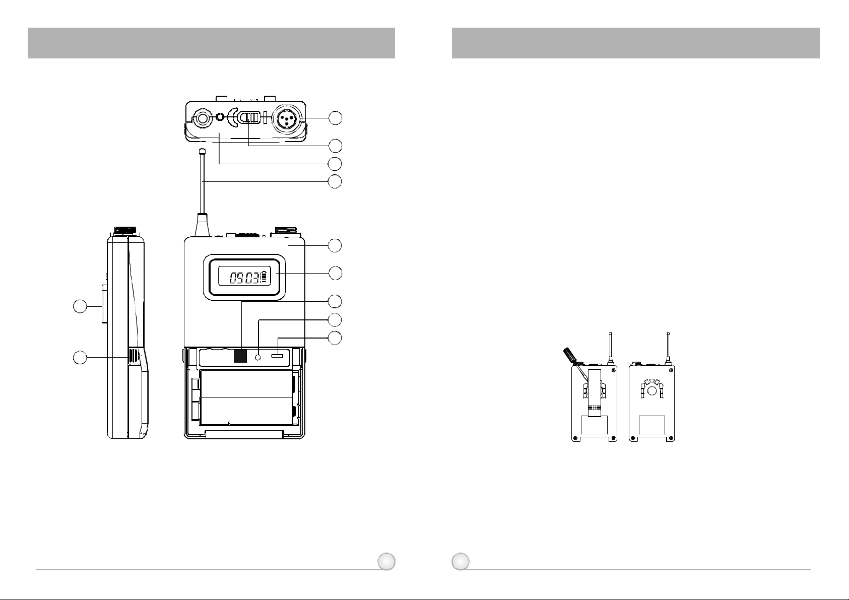
BELTPACKTRANSMITTER BELTPACKTRANSMITTER
1.PARTSNAMESANDFUNCTIONS
LOW
ACTSERIES
11
10
GROUP
CHANNEL
GAIN MTGT
3.BatteryStatusIndicator:Indicatesthepoweron/offandbatterystatus.
(a)Whenpowerswitchisturnedon:TheLEDindicatorflashesbriefly,
indicatingnormalbatterystatus.
(b)WhenREDlightilluminatesateitherpoweronorduringusage:The
OFF ON BATT.
1
2
3
4
batterylevelislow,therefore,anewbatteryreplacementisthusnecessary.
4.TransmittingAntenna:1/4transmittingantenna.
λ
5.TransmitterHousing:PackagesthePCBandbattery.
6.FunctionsofLCDDisplay
7.ACTSignalReceptor:ReceivingACTsignalandadjustingfrequency
automatically.
8.GainControl:Adjuststhedesirousinputgain.
9.GT/MTLevelSelector:SwitchGTpositionforelectricguitarusageand"Line
5
In".GainControlisirrelevantfor"GT".Switchto"MT"forcondenser
microphoneorwiredmicrophone.GainControlworksin"MT"forinput
BAT
6
sensitivityadjusting.
10.BatteryCompartmentandCover:Accommodatestwo1.5V(AA)batteries.
7
11.DetachableBeltClip:Allows360degreesrotatingtosuittransmittingangles.
Todetachsimplyuseascrewdriverata45degreeangletounfasten.see
8
diagram.
9
(Fig.1)
1.AFInputJack:Connectstoalavaliereorheadsetmicrophone.(See5ways
ofconnectiononAFInputConnections)
2.PowerSwitch:Tumspower"on"and"off"ofthetransmitter.
18 19
Page 12
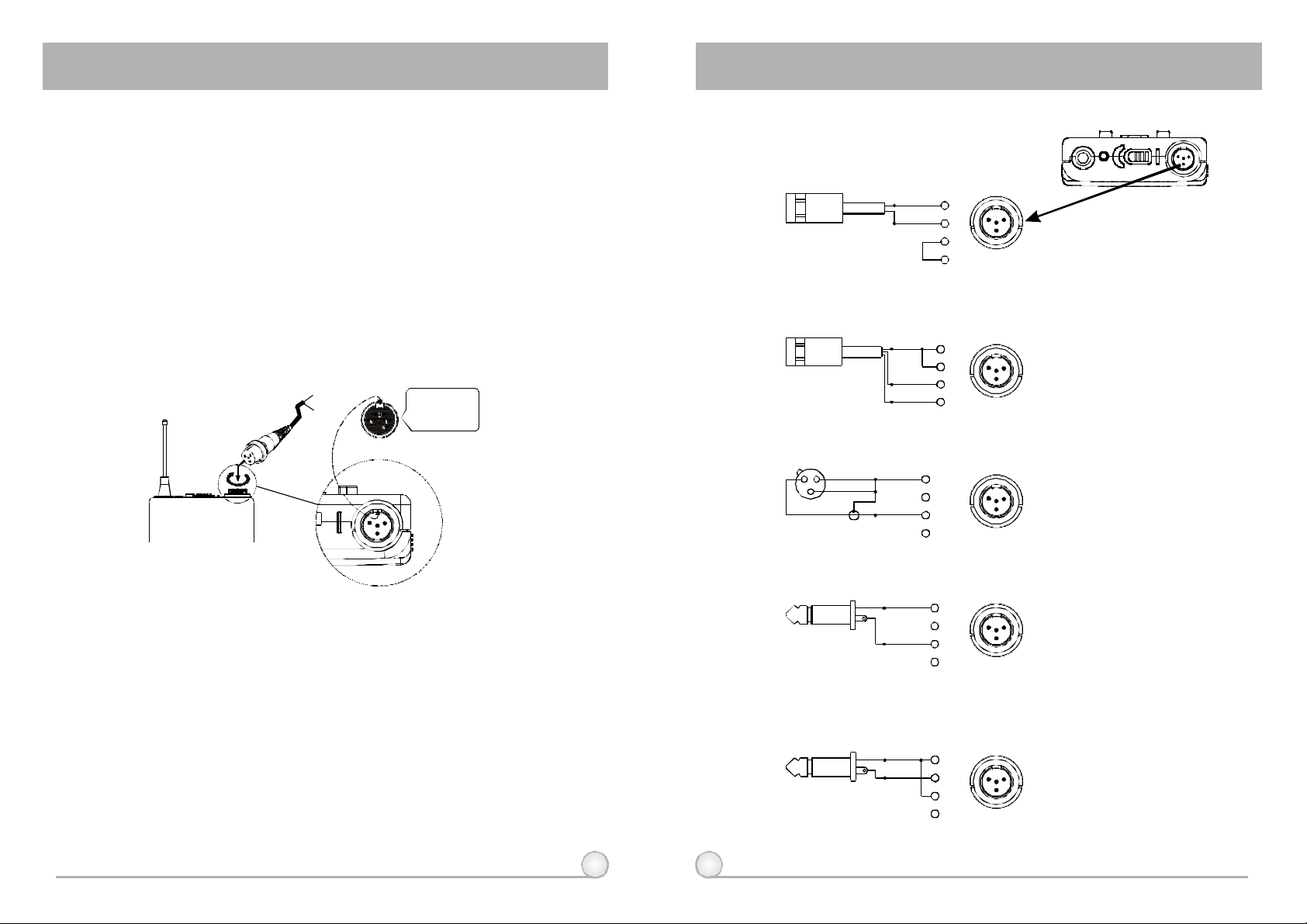
BELTPACKTRANSMITTER BELTPACKTRANSMITTER
2.OPERATINGINSTRUCTIONS
1.ToadjustGT/MTSwitch(10),andGainControl(8),simplypushdownboth
snaplocksonthesidesofbatterycoverandflipitbackwardstoexposethe
adjustmentpanel.
2.Beforepoweron,ascertainifsamechannel(7)wassetupforbothreceiver
andmicrophone.Ifnotadjusttosamechannelaccordingly.
3.TheLEDindicatorflashesbrieflywhenpoweronindicatingnormalbattery
status.Ifnoflashoccursithaseithernobattery,thebatteryisdrainedor
installedincorrectly.Changeaccordingly.
4.Plugthemicrophoneconnectorintotheinputjack(1)andtightenthe
connectorscrewbyclockwisedirectionasshownin(Fig.2).
CapsuleConnector
Headset
Lavalier
1 3
4
2
Pleaseaimof
thefillister
andinsertthe
connector
3.AF4-PININPUTCONNECTIONMETHODS
(1)2-WireElectretCondenserMicrophoneCapsule
PIN
SHIELD
AUDIO
(2)3-WireElectretCondenserMicrophoneCapsule
SHIELD
AUDIO
BIAS
(3)DynamicMicrophone
2 1
3
SHIELD
AUDIO
PIN
1
4
2
3
4
PIN
1
2
3
4
1
2
3
4
1
1 3
1 3
3
2
4
2
4
2
4
LOW
1 3
2
OFF ON BATT.
(Fig.2)
20 21
(4)ElectricGuitar
SHIELD
AUDIO
(5)Line-in(Impedance8KATT.10dB)Ω
SHIELD
AUDIO
PIN
PIN
1
2
3
4
1
2
3
4
4
1
3
2
4
1
3
2
Page 13
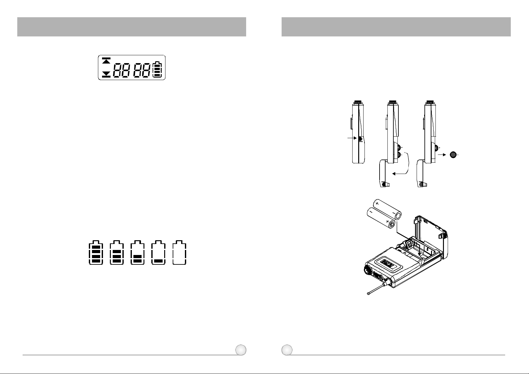
BELTPACKTRANSMITTER BELTPACKTRANSMITTER
4. FUNCTIONSOFLCDDISPLAY
GROUP
CHANNEL
ERR
1.ERRMessage:When"ERR"appears,itmeans"OperationError".Pleaserefer
tothefollowingcodestodiagnosewhicherroryouareexperiencing.
ERRno01EEPROMisnotbeingprogrammedorinternaldataerror.
ERRno02Fortestingonly.
ERRno03Thefrequencyyouareabouttoprogramintothesystemexceeds
ERRno04Thefrequencyyouareabouttoprogramintothesystemisbelow
2."Group"&"Channel":Whenbothitemsareshown,theyindicatethattheuser
iscurrentlyusingthepre-programmedfrequencyinthereceiver.
3."Channel"Only:If"Channel"istheonlyitemshowninthedisplay,itindicates
theuserisusingthepersonalizedfrequency.
→
→
→
microphone'supperlimit.(Atthistime,microphoneisstill
operatableandthefrequencyremainsunchanged.Toclearthe
"ERR"messageinLCDdisplay,simplyturnoffthepowerand
switchbackon.)
→
microphone'sfrequencylowerlimit.(Atthistime,microphoneisstill
operatableandthefrequencyremainsunchanged.Toclearthe
"ERR"messageinLCDdisplay,simplyturnoffthepowerand
switchbackon.)
BAT
5.BATTERYINSTALLATION
1.Pushingdownbothsnaplocksonthesidesofbatterycovertoopenbattery
cover.Takeoutthebatteries.Fig.3).
2.Insertatwo1.5(AA)batteriesintothebatterycompartmentaccordingtothe
correctpolarityasshowninFig.3).Thenpushuptoclosethebattery
compartmentasshowninFig.4).
(Fig.3)
4.BatteryStatus:
100% 80% 40% 10% 0%
BatteryStatus:Whenthebatteryhaslessthan10%powerremaining,batteries
mustbereplaced.Ifundervoltagecontinues,LCDwillshow"PoFF"andshutdown
thesystemtoavoidbatterybeingover-discharged.
5.SwitchOff:
Whenswitchthepowerknobto"Off"position,LCDwillshow"PoFF"first.
Then,thesystemiscompletelyshutdownandnofurthermessagewillbe
displayed.
22 23
(Fig.4)
PS:Whenthemicrophoneisnotinuse:
Makesurethepowerofthemicrophoneisoff.Ifthemicrophonewillnot
beusedforsometime,pleaseremovethebatteriesfromthebattery
compartmenttoavoidbatteryleakageandresultindamagedbattery
springsandcircuit.Ifarechargeablebatterywasused,takeitoutand
rechargeit.
 Loading...